EP1997008B1 - State transaction bundling for improved redundancy - Google Patents
State transaction bundling for improved redundancy Download PDFInfo
- Publication number
- EP1997008B1 EP1997008B1 EP07734909A EP07734909A EP1997008B1 EP 1997008 B1 EP1997008 B1 EP 1997008B1 EP 07734909 A EP07734909 A EP 07734909A EP 07734909 A EP07734909 A EP 07734909A EP 1997008 B1 EP1997008 B1 EP 1997008B1
- Authority
- EP
- European Patent Office
- Prior art keywords
- transaction message
- control system
- software module
- software modules
- module
- Prior art date
- Legal status (The legal status is an assumption and is not a legal conclusion. Google has not performed a legal analysis and makes no representation as to the accuracy of the status listed.)
- Not-in-force
Links
Images

Classifications
-
- H—ELECTRICITY
- H04—ELECTRIC COMMUNICATION TECHNIQUE
- H04L—TRANSMISSION OF DIGITAL INFORMATION, e.g. TELEGRAPHIC COMMUNICATION
- H04L49/00—Packet switching elements
- H04L49/55—Prevention, detection or correction of errors
-
- G—PHYSICS
- G06—COMPUTING OR CALCULATING; COUNTING
- G06F—ELECTRIC DIGITAL DATA PROCESSING
- G06F11/00—Error detection; Error correction; Monitoring
- G06F11/07—Responding to the occurrence of a fault, e.g. fault tolerance
- G06F11/16—Error detection or correction of the data by redundancy in hardware
- G06F11/20—Error detection or correction of the data by redundancy in hardware using active fault-masking, e.g. by switching out faulty elements or by switching in spare elements
- G06F11/2097—Error detection or correction of the data by redundancy in hardware using active fault-masking, e.g. by switching out faulty elements or by switching in spare elements maintaining the standby controller/processing unit updated
-
- H—ELECTRICITY
- H04—ELECTRIC COMMUNICATION TECHNIQUE
- H04Q—SELECTING
- H04Q3/00—Selecting arrangements
- H04Q3/42—Circuit arrangements for indirect selecting controlled by common circuits, e.g. register controller, marker
- H04Q3/54—Circuit arrangements for indirect selecting controlled by common circuits, e.g. register controller, marker in which the logic circuitry controlling the exchange is centralised
- H04Q3/545—Circuit arrangements for indirect selecting controlled by common circuits, e.g. register controller, marker in which the logic circuitry controlling the exchange is centralised using a stored program
- H04Q3/54541—Circuit arrangements for indirect selecting controlled by common circuits, e.g. register controller, marker in which the logic circuitry controlling the exchange is centralised using a stored program using multi-processor systems
- H04Q3/54558—Redundancy, stand-by
-
- G—PHYSICS
- G06—COMPUTING OR CALCULATING; COUNTING
- G06F—ELECTRIC DIGITAL DATA PROCESSING
- G06F11/00—Error detection; Error correction; Monitoring
- G06F11/07—Responding to the occurrence of a fault, e.g. fault tolerance
- G06F11/16—Error detection or correction of the data by redundancy in hardware
- G06F11/20—Error detection or correction of the data by redundancy in hardware using active fault-masking, e.g. by switching out faulty elements or by switching in spare elements
- G06F11/202—Error detection or correction of the data by redundancy in hardware using active fault-masking, e.g. by switching out faulty elements or by switching in spare elements where processing functionality is redundant
- G06F11/2038—Error detection or correction of the data by redundancy in hardware using active fault-masking, e.g. by switching out faulty elements or by switching in spare elements where processing functionality is redundant with a single idle spare processing component
-
- H—ELECTRICITY
- H04—ELECTRIC COMMUNICATION TECHNIQUE
- H04Q—SELECTING
- H04Q2213/00—Indexing scheme relating to selecting arrangements in general and for multiplex systems
- H04Q2213/1305—Software aspects
-
- H—ELECTRICITY
- H04—ELECTRIC COMMUNICATION TECHNIQUE
- H04Q—SELECTING
- H04Q2213/00—Indexing scheme relating to selecting arrangements in general and for multiplex systems
- H04Q2213/13103—Memory
-
- H—ELECTRICITY
- H04—ELECTRIC COMMUNICATION TECHNIQUE
- H04Q—SELECTING
- H04Q2213/00—Indexing scheme relating to selecting arrangements in general and for multiplex systems
- H04Q2213/13167—Redundant apparatus
Definitions
- the invention relates to synchronization of redundant control systems having multiple dependencies, and in particular to transaction messaging within such synchronization.
- synchronicity between the control systems is maintained by means of transaction messages.
- software modules on the active control system are triggered to update stored state information.
- the software module also sends a transaction message to the standby control system, and in response the standby control system updates its version of the stored state information. For example, if a channel is created, a software module is called to populate the channel table entry.
- the software module also sends a transaction message to the standby control system to indicate the channel table entry change.
- the standby control system responds to this transaction message by populating its own channel table entry. In this way, when a switchover occurs, the newly active control system will have up to date information which accurately reflects the state of a system being controlled.
- an event may trigger multiple transaction messages.
- an event triggers a first software module to update state information and send a transaction message to the standby control system.
- the first software module also triggers a second software module responsible for maintaining state information which is dependent on the state information maintained by the first software module.
- the second software module updates the state information on the active control system, then sends its own transaction message to the standby control system.
- the first software module a channel module
- it may trigger the second software module (a forwarding module) to allocate a forwarding index for the new channel.
- the first software module and the second software module each send their own transaction message to the standby control system.
- the second software module may trigger a third software module with its own transaction message, and so on.
- the standby control system would then have incomplete state information. This can lead to various problems, such as incomplete state information or leakage of resources. For example, if the channel module above sent its transaction message but the transaction message of the forwarding module was not sent in time (i.e. before the active control system failed), then the standby control system (now the newly active control system) will act as if the channel has been created and may assume that the forwarding index has been allocated. It is only when use of the new channel is attempted will the absence of information become known and an error occur.
- the standby control system will have processed the transaction message from the forwarding module and will have allocated a forwarding index for a non-existent channel.
- the channel module on the newly active control system will trigger a forwarding module and a new forwarding index will be allocated. This results in leakage of forwarding indices.
- intra-module audits are carried out following a switchover.
- An intra-module audit examines the state information of a software module against each of its dependent software modules to determine whether all the interdependent state information is present, and to allocate or deallocate resources in an attempt to correct any deficiencies.
- intra-module audits can be extremely complex, since the dependencies between software modules are generally not as simple as in the example given above. Compounding the problem is that this complexity is called upon just after a switchover when there is no additional standby control system. The complexity is also hard to maintain and debug.
- Document US 2004073828 deals with a system which provides a transparent variable state mirroring system providing a protocol and a supporting software architecture for an object-oriented messaging scheme used to maintain data synchronization between an active entity and a standby entity.
- Document US 2003046604 relates to a method for implementing protocol redundancy in a router.
- the invention relates to providing redundancy of multi protocol label switching.
- a method of conveying updates of stored state information to a standby control system is provided as defined in claim 1. Particular features of this method are provided as defined in claim 2 to 4.
- a computer readable medium is provided as defined in claim 5. Particular feature of this computer readable medium is provided as defined in claim 6.
- the methods and apparatus of the present invention allow related transaction messages to be bundled and sent together.
- a standby control system is thereby able to recreate the state of the system being controlled completely, including all interdependent states for an event or update.
- This removes the need for intra-module auditing, greatly simplifying synchronization between the active control system and the standby control system, and enabling much smoother switchovers.
- the risk of software error is distributed over time instead of all at once just after a switchover.
- the software responsible for ensuring that dependencies between software modules are maintained runs all the time on the active control system during bundling of transaction messages, and receives better test coverage and soak time instead of a one-shot audit post switchover.
- the need for running a complex intra-module audit immediately after switchover is avoided.
- the risk of a failure of the standby control system due to an error in complex intra-module auditing, leaving the system with no system controls since the primary control system has just failed prior to the switchover, is minimized or even eliminated.
- an active control system includes software modules which perform actions that alter state information of a system being controlled by the control system.
- the alteration of the state information is conveyed to a standby control system in order to maintain synchronicity of stored state information between the active control system and the standby control system, although this conveyance is not necessarily by the software module that altered the state information.
- Each software module may call other software modules or may be called by other software modules.
- the software modules are generally organized in a hierarchical manner.
- a first software module that calls a second software module is referred to as the calling software module of the second software module, and the second software module is referred to as a called software module of the first software module.
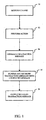
- FIG. 1 a flowchart of a method carried out by a software module on a control system according to one embodiment of the invention is shown.
- the software module is called. This may be by another software module, or by a network administrator.
- the software module performs an action which updates the state information of the system being controlled by the control system.
- the software module generates a transaction message for eventual use by the standby control system. The transaction message reflects changes to the state information made by the software module in performing the action at step 12.
- the software module bundles any transaction messages received from other called software modules with the transaction message generated at step 14.
- the called software modules will usually have been called as part of the action performed at step 12, but may more generally be called at any time at which the software module is designed to call called software modules. It should also be noted that there may not actually be any called software modules or any returned transaction messages, if this software module is at or near the bottom of the software module hierarchy for a triggering event.
- the software module outputs the bundled transaction message, which may include only this software module's transaction message if this software module is at or near the bottom of the software module hierarchy.
- the bundled transaction message will usually be output as a return value to be read by a calling software module at the calling software module's own execution of step 16. However, if this software module has no calling software module and is at the top of the software module hierarchy for a triggering event, then the bundled transaction message is output by transmitting the bundled transaction message to the standby control system. The nature of the output will depend on how the software module has been coded.
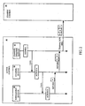
- An active control system 40 includes three software modules: a channel creation module 42 which is a top software module triggered by an event; a channel module 44; and a forwarding module 46. Below each software module in FIG. 2 is a time line, with time progressing downward.
- the channel creation module 42 is triggered when a channel is created, such as by a network administrator.
- the channel creation module 42 notes the event, in particular that a new channel has been created.
- the channel creation module calls the channel module 44.
- the channel module 44 performs an action, namely populating a channel table entry.
- the channel module 44 then calls the forwarding module 46.
- the forwarding module 46 performs an action, namely allocating a forwarding index to the channel.
- the forwarding module 46 In performing this action, the forwarding module 46 generates a transaction message B. However, instead of transmitting this transaction message to a standby control system 48, the forwarding module 46 sends the transaction message to the channel module 44 as part of its return value.
- the channel module 44 receives the transaction message B and bundles it with its own transaction message A which was generated as a result of performing the action of populating the channel table entry.
- the channel module 44 sends the bundled transaction message to the channel creation module 42 as part of its return value.
- the channel creation module 42 bundles the received transaction messages AB with its own transaction message E which was generated as a result of performing the action of creating the channel. Because the channel creation module 42 is a top software module, it outputs the bundled transaction message EAB to the standby control system 48.
- the standby control system 48 then has complete state information relating to the triggering event of creating the new channel, and can update its own stored state information.
- a channel creation module 50 within the standby control system 48 receives the bundled transaction message EAB sent by the channel creation module 42 of the active control system 40.
- the channel creation module 50 extracts the transaction message E and notes the event by updating the state information stored on the standby control system 48 to reflect creation of the new channel.
- the channel creation module 50 then sends the partially debundled transaction message AB to a channel module 52 (similar to the channel module 44 on the active control system 40).
- the channel module 52 extracts the transaction message A and performs the corresponding action, namely populating a channel entry table as indicated by the transaction message A.
- the channel module 52 then sends the partially debundled transaction message B (containing at this point in this example only one transaction message) to a forwarding module 54 (similar to the forwarding module 46 on the active control system 40).
- the forwarding module 54 extracts the transaction message B and performs the corresponding action, namely allocating a forwarding index to the channel.
- the forwarding module 54 then sends a return to the channel module 52, which in turn sends a return to the channel creation module 50.
- control system has been described as software modules on an active control system. This has been for ease of explanation in order to identify one control system as an active control system and a separate control system as a standby control system. Since control systems may generally be either an active control system or a standby control system at any point in time, the invention will be understood more generally to related to software modules on any control system.
Landscapes
- Engineering & Computer Science (AREA)
- Theoretical Computer Science (AREA)
- Computer Networks & Wireless Communication (AREA)
- Quality & Reliability (AREA)
- Physics & Mathematics (AREA)
- General Engineering & Computer Science (AREA)
- General Physics & Mathematics (AREA)
- Signal Processing (AREA)
- Hardware Redundancy (AREA)
- Debugging And Monitoring (AREA)
Abstract
Description
- The invention relates to synchronization of redundant control systems having multiple dependencies, and in particular to transaction messaging within such synchronization.
- In redundant control systems, such as redundant control cards, synchronicity between the control systems is maintained by means of transaction messages. When the state of the system being controlled, such as a communications network, changes, software modules on the active control system are triggered to update stored state information. The software module also sends a transaction message to the standby control system, and in response the standby control system updates its version of the stored state information. For example, if a channel is created, a software module is called to populate the channel table entry. The software module also sends a transaction message to the standby control system to indicate the channel table entry change. The standby control system responds to this transaction message by populating its own channel table entry. In this way, when a switchover occurs, the newly active control system will have up to date information which accurately reflects the state of a system being controlled.
- In systems having state dependencies, an event may trigger multiple transaction messages. In such systems, an event triggers a first software module to update state information and send a transaction message to the standby control system. The first software module also triggers a second software module responsible for maintaining state information which is dependent on the state information maintained by the first software module. The second software module updates the state information on the active control system, then sends its own transaction message to the standby control system. Continuing the example given above, once the first software module (a channel module) has populated the channel table entry, it may trigger the second software module (a forwarding module) to allocate a forwarding index for the new channel. The first software module and the second software module each send their own transaction message to the standby control system. Of course, there may be more than two levels of dependency, and the second software module may trigger a third software module with its own transaction message, and so on.
- A problem can arise if a switchover occurs while transaction messages are being sent. The standby control system would then have incomplete state information. This can lead to various problems, such as incomplete state information or leakage of resources. For example, if the channel module above sent its transaction message but the transaction message of the forwarding module was not sent in time (i.e. before the active control system failed), then the standby control system (now the newly active control system) will act as if the channel has been created and may assume that the forwarding index has been allocated. It is only when use of the new channel is attempted will the absence of information become known and an error occur. If on the other hand it was the channel module that was unable to send its transaction message in time, then the standby control system will have processed the transaction message from the forwarding module and will have allocated a forwarding index for a non-existent channel. When the channel is created anew on the newly active control system, the channel module on the newly active control system will trigger a forwarding module and a new forwarding index will be allocated. This results in leakage of forwarding indices.
- To overcome this risk, intra-module audits are carried out following a switchover. An intra-module audit examines the state information of a software module against each of its dependent software modules to determine whether all the interdependent state information is present, and to allocate or deallocate resources in an attempt to correct any deficiencies. However, intra-module audits can be extremely complex, since the dependencies between software modules are generally not as simple as in the example given above. Compounding the problem is that this complexity is called upon just after a switchover when there is no additional standby control system. The complexity is also hard to maintain and debug.
- Document
US 2004073828 deals with a system which provides a transparent variable state mirroring system providing a protocol and a supporting software architecture for an object-oriented messaging scheme used to maintain data synchronization between an active entity and a standby entity. - Document
US2004153624 discloses a system which comprises one or more switches under the control of multiple control processors. - Document
US 2003046604 relates to a method for implementing protocol redundancy in a router. In particular, the invention relates to providing redundancy of multi protocol label switching. - In accordance with an aspect of the invention, a method of conveying updates of stored state information to a standby control system is provided as defined in claim 1. Particular features of this method are provided as defined in claim 2 to 4. In accordance with yet another aspect of the invention a computer readable medium is provided as defined in claim 5. Particular feature of this computer readable medium is provided as defined in claim 6.
- The methods and apparatus of the present invention allow related transaction messages to be bundled and sent together. A standby control system is thereby able to recreate the state of the system being controlled completely, including all interdependent states for an event or update. This removes the need for intra-module auditing, greatly simplifying synchronization between the active control system and the standby control system, and enabling much smoother switchovers. The risk of software error is distributed over time instead of all at once just after a switchover. The software responsible for ensuring that dependencies between software modules are maintained runs all the time on the active control system during bundling of transaction messages, and receives better test coverage and soak time instead of a one-shot audit post switchover. The need for running a complex intra-module audit immediately after switchover is avoided. The risk of a failure of the standby control system due to an error in complex intra-module auditing, leaving the system with no system controls since the primary control system has just failed prior to the switchover, is minimized or even eliminated.
- The features and advantages of the invention will become more apparent from the following detailed description of the preferred embodiment(s) with reference to the attached figures, wherein:
-
FIG.1 is a flowchart of a method carried out by a software module on a control system according to one embodiment of the invention; -
FIG. 2 is a messaging diagram of an example transaction messaging in an active control system according to one embodiment of the invention; and -
FIG. 3 is a messaging diagram of an example transaction messaging in a standby control system according to one embodiment of the invention. - It will be noted that in the attached figures, like features bear similar labels.
- According to one embodiment of the invention, an active control system includes software modules which perform actions that alter state information of a system being controlled by the control system. The alteration of the state information is conveyed to a standby control system in order to maintain synchronicity of stored state information between the active control system and the standby control system, although this conveyance is not necessarily by the software module that altered the state information.
- Each software module may call other software modules or may be called by other software modules. The software modules are generally organized in a hierarchical manner. A first software module that calls a second software module is referred to as the calling software module of the second software module, and the second software module is referred to as a called software module of the first software module.
- Referring to
FIG. 1 , a flowchart of a method carried out by a software module on a control system according to one embodiment of the invention is shown. Atstep 10 the software module is called. This may be by another software module, or by a network administrator. Atstep 12 the software module performs an action which updates the state information of the system being controlled by the control system. Atstep 14 the software module generates a transaction message for eventual use by the standby control system. The transaction message reflects changes to the state information made by the software module in performing the action atstep 12. - At
step 16 the software module bundles any transaction messages received from other called software modules with the transaction message generated atstep 14. The called software modules will usually have been called as part of the action performed atstep 12, but may more generally be called at any time at which the software module is designed to call called software modules. It should also be noted that there may not actually be any called software modules or any returned transaction messages, if this software module is at or near the bottom of the software module hierarchy for a triggering event. - At
step 18 the software module outputs the bundled transaction message, which may include only this software module's transaction message if this software module is at or near the bottom of the software module hierarchy. The bundled transaction message will usually be output as a return value to be read by a calling software module at the calling software module's own execution ofstep 16. However, if this software module has no calling software module and is at the top of the software module hierarchy for a triggering event, then the bundled transaction message is output by transmitting the bundled transaction message to the standby control system. The nature of the output will depend on how the software module has been coded. - In this way, individual software modules do not transmit their own transaction messages independently to the standby control system. Rather, transaction messages within a software module hierarchy are bundled together as they are passed to calling software modules as part of return values. Only the top software module conveys information to the standby control system, and this is done by transmitting a bundled transaction message which includes transaction messages from all software modules which are eventually called as part of the software module hierarchy triggered by an event.
- Referring to
FIG. 2 , an example series of transaction messages is shown in accordance with one embodiment of the invention. Anactive control system 40 includes three software modules: achannel creation module 42 which is a top software module triggered by an event; achannel module 44; and aforwarding module 46. Below each software module inFIG. 2 is a time line, with time progressing downward. Thechannel creation module 42 is triggered when a channel is created, such as by a network administrator. Thechannel creation module 42 notes the event, in particular that a new channel has been created. The channel creation module calls thechannel module 44. Thechannel module 44 performs an action, namely populating a channel table entry. Thechannel module 44 then calls theforwarding module 46. Theforwarding module 46 performs an action, namely allocating a forwarding index to the channel. - In performing this action, the
forwarding module 46 generates a transaction message B. However, instead of transmitting this transaction message to astandby control system 48, theforwarding module 46 sends the transaction message to thechannel module 44 as part of its return value. Thechannel module 44 receives the transaction message B and bundles it with its own transaction message A which was generated as a result of performing the action of populating the channel table entry. Thechannel module 44 sends the bundled transaction message to thechannel creation module 42 as part of its return value. Thechannel creation module 42 bundles the received transaction messages AB with its own transaction message E which was generated as a result of performing the action of creating the channel. Because thechannel creation module 42 is a top software module, it outputs the bundled transaction message EAB to thestandby control system 48. Thestandby control system 48 then has complete state information relating to the triggering event of creating the new channel, and can update its own stored state information. - Referring to
FIG. 3 , an example series of transaction messages within the standby control system according to one embodiment of the invention is shown. Achannel creation module 50 within the standby control system 48 (similar to thechannel creation module 42 within the active control system 40) receives the bundled transaction message EAB sent by thechannel creation module 42 of theactive control system 40. Thechannel creation module 50 extracts the transaction message E and notes the event by updating the state information stored on thestandby control system 48 to reflect creation of the new channel. Thechannel creation module 50 then sends the partially debundled transaction message AB to a channel module 52 (similar to thechannel module 44 on the active control system 40). Thechannel module 52 extracts the transaction message A and performs the corresponding action, namely populating a channel entry table as indicated by the transaction message A. Thechannel module 52 then sends the partially debundled transaction message B (containing at this point in this example only one transaction message) to a forwarding module 54 (similar to theforwarding module 46 on the active control system 40). Theforwarding module 54 extracts the transaction message B and performs the corresponding action, namely allocating a forwarding index to the channel. Theforwarding module 54 then sends a return to thechannel module 52, which in turn sends a return to thechannel creation module 50. - The invention has been described as software modules on an active control system. This has been for ease of explanation in order to identify one control system as an active control system and a separate control system as a standby control system. Since control systems may generally be either an active control system or a standby control system at any point in time, the invention will be understood more generally to related to software modules on any control system.
Claims (6)
- A method of conveying updates of stored state information to a standby control system (48), characterized in that the method comprises:performing (12) in each of a plurality of software modules (42, 44, 46), organized in a hierarchy from a top software module (42) to a bottom software module (46) an action which updates a portion of the stored state information;generating (14), in each of the software modules (42, 44, 46), a transaction message (E, A, B) reflecting the updated portion of the stored state information;receiving, in at least one of the software modules (44, 42), at least one transaction message (B, AB) from at least one called software module (46, 44) of the plurality of software modules (42, 44, 46) ;in said at least one of the software modules (44, 42) receiving at least one transaction message (B, AB), bundling (16) said at least one received transaction message (B, AB) with the generated transaction message (A, E) into a bundled transaction message (AB, EAB) ; andtransmitting the bundled transaction message (EAB) to the standby control system (48) from only the top software module (42) not called by any of the plurality of software modules (44, 46).
- The method of claim 1 further comprising passing at least one generated transaction message (B, A) from the software module (46, 44) which generated the transaction message (B, A) to a calling software module (44, 42) as part of a return value.
- A method of updating stored state information in a standby control system (48),
characterized in that, the standby control system (48) comprising a plurality of software modules (50, 52, 54) organized in a hierarchy from a top software module (50) to a bottom software module (54), said method comprises:at only the top software module (50) not called by any of the other of the plurality of software modules (52, 54), receiving a bundled transaction message (EAB) transmitted by an active control system (40) according to the method of claims 1 or 2,extracting a plurality of transaction messages (B, A, E) from the bundled transaction message (EAB); andat each of the plurality of software modules (50, 52, 54), updating a portion of the stored state information in accordance with at least one of the plurality of transaction messages (B, A, E). - The method of claim 3 wherein extracting a plurality of transaction messages (B, A, E) comprises at least one of the software modules (50, 52) extracting at least one of the plurality of transaction messages (B, A, E) from the bundled transaction message (EAB) leaving a partially debundled transaction message (AB, B) and passing the partially debundled transaction message (AB, B) to another of the software modules (52, 54).
- A computer-readable medium storing instructions which can be processed by a computer processor, comprising:instructions for performing (12) an action which updates state information stored on a control system;instructions for generating (14) a transaction message (E, A, B) reflecting an update to the state information;characterized by further comprising:i nstructions for receiving at least one transaction message (B, AB) from at least one called software module (46, 44) of a plurality of software modules (42, 44,46) organized in a hierarchy from a top software module (42) to a bottom software module (46), the at least one transaction message (B, AB) being received as part of a return value from each of the at least one called software module (46,44);i nstructions for bundling (16) the at least one received transaction message (B, AB) with the generated transaction message (A, E) into a bundled transaction message (AB, EAB); andi nstructions for outputting (18) the bundled transaction message (EAB) to a standby control system (48) from only the top software module (42) not called by any of the plurality of software modules (44, 46).
- The computer-readable medium of claim 5 wherein the instructions for outputting the bundled transaction message (EAB) comprise instructions for including the bundled transaction message (EAB) as part of a return value.
Applications Claiming Priority (2)
| Application Number | Priority Date | Filing Date | Title |
|---|---|---|---|
| US11/371,926 US7509528B2 (en) | 2006-03-10 | 2006-03-10 | Transaction bundling for improved redundancy |
| PCT/IB2007/001765 WO2007105117A2 (en) | 2006-03-10 | 2007-03-08 | State transaction bundling for improved redundancy |
Publications (2)
| Publication Number | Publication Date |
|---|---|
| EP1997008A2 EP1997008A2 (en) | 2008-12-03 |
| EP1997008B1 true EP1997008B1 (en) | 2011-10-26 |
Family
ID=38480324
Family Applications (1)
| Application Number | Title | Priority Date | Filing Date |
|---|---|---|---|
| EP07734909A Not-in-force EP1997008B1 (en) | 2006-03-10 | 2007-03-08 | State transaction bundling for improved redundancy |
Country Status (5)
| Country | Link |
|---|---|
| US (1) | US7509528B2 (en) |
| EP (1) | EP1997008B1 (en) |
| CN (1) | CN101401074B (en) |
| AT (1) | ATE530983T1 (en) |
| WO (1) | WO2007105117A2 (en) |
Families Citing this family (5)
| Publication number | Priority date | Publication date | Assignee | Title |
|---|---|---|---|---|
| US8423831B2 (en) * | 2006-07-11 | 2013-04-16 | Oracle America, Inc. | System and method for performing auditing and correction |
| US8074094B2 (en) * | 2007-06-30 | 2011-12-06 | Cisco Technology, Inc. | Session redundancy using a replay model |
| EP2259204A1 (en) | 2008-03-28 | 2010-12-08 | Panasonic Corporation | Software updating apparatus, software updating system, invalidation method, and invalidation program |
| WO2009118800A1 (en) * | 2008-03-28 | 2009-10-01 | パナソニック株式会社 | Software updating apparatus, software updating system, alteration verification method and alteration verification program |
| JP5960678B2 (en) * | 2011-03-15 | 2016-08-02 | パナソニック株式会社 | Tamper monitoring system, management device, protection control module and detection module |
Family Cites Families (6)
| Publication number | Priority date | Publication date | Assignee | Title |
|---|---|---|---|---|
| US6910148B1 (en) * | 2000-12-07 | 2005-06-21 | Nokia, Inc. | Router and routing protocol redundancy |
| EP1388078A1 (en) * | 2001-05-03 | 2004-02-11 | Nokia Inc. | Method and system for implementing mpls redundancy |
| US20040073828A1 (en) * | 2002-08-30 | 2004-04-15 | Vladimir Bronstein | Transparent variable state mirroring |
| US7194652B2 (en) * | 2002-10-29 | 2007-03-20 | Brocade Communications Systems, Inc. | High availability synchronization architecture |
| US7376078B1 (en) * | 2004-03-24 | 2008-05-20 | Juniper Networks, Inc. | Selective replay of a state information within a computing device |
| US7127659B2 (en) * | 2004-08-02 | 2006-10-24 | Qualcomm Incorporated | Memory efficient LDPC decoding methods and apparatus |
-
2006
- 2006-03-10 US US11/371,926 patent/US7509528B2/en not_active Expired - Fee Related
-
2007
- 2007-03-08 EP EP07734909A patent/EP1997008B1/en not_active Not-in-force
- 2007-03-08 CN CN200780008433XA patent/CN101401074B/en not_active Expired - Fee Related
- 2007-03-08 WO PCT/IB2007/001765 patent/WO2007105117A2/en not_active Ceased
- 2007-03-08 AT AT07734909T patent/ATE530983T1/en not_active IP Right Cessation
Also Published As
| Publication number | Publication date |
|---|---|
| WO2007105117A3 (en) | 2007-12-13 |
| WO2007105117A2 (en) | 2007-09-20 |
| US20070214385A1 (en) | 2007-09-13 |
| ATE530983T1 (en) | 2011-11-15 |
| US7509528B2 (en) | 2009-03-24 |
| CN101401074B (en) | 2013-04-03 |
| CN101401074A (en) | 2009-04-01 |
| EP1997008A2 (en) | 2008-12-03 |
Similar Documents
| Publication | Publication Date | Title |
|---|---|---|
| US11336465B2 (en) | Sending cross-chain authenticatable messages | |
| KR100575497B1 (en) | Fault Tolerant Computer System | |
| AU4516493A (en) | System for changing software during computer operation | |
| US20200177391A1 (en) | Sending cross-chain authenticatable messages | |
| WO2020024469A1 (en) | Service processing method, calling management system and computer device | |
| EP1997008A2 (en) | State transaction bundling for improved redundancy | |
| CN112328406A (en) | A TCC-based microservice distributed transaction system and business processing method | |
| EP0954918A1 (en) | System and method for communications and process management in a distributed telecommunications switch | |
| CN106648858A (en) | Interactive management system for C# interface data | |
| CN114006927A (en) | Service message processing method and processing device thereof, electronic equipment and storage medium | |
| CN106385330A (en) | Network function virtualization composer realization method and device | |
| CN110619579A (en) | Method and device for reporting disk at highest speed and computer readable storage medium | |
| CN119996420A (en) | Blockchain cross-chain communication system and communication method for multi-chain architecture | |
| CN100362761C (en) | A method for realizing single board switching | |
| CN119336842A (en) | Transaction monitoring IDC synchronization method under the disaster recovery architecture of 5G enhanced call operation management platform | |
| CN106657390A (en) | Cluster file system directory isolation method, cluster file system directory isolation device and cluster file system directory isolation system | |
| CN100465913C (en) | A configuration recovery device and method | |
| CN110935168B (en) | Distributed ID generation method, device and equipment for global uniform architecture | |
| CN117194147A (en) | Container cluster monitoring system, method, device and storage medium | |
| JP2006285443A (en) | Object relief system and method | |
| US7032021B1 (en) | Method and network element for operating a telecommunications network | |
| CN114021169B (en) | Data disclosure methods and apparatus | |
| US6735296B2 (en) | Method and apparatus for swapping telephone numbers between switching modules | |
| CN111562993B (en) | Web application system for dynamically switching data sources | |
| CN114968407B (en) | Plug-in calling method, device, electronic equipment and storage medium |
Legal Events
| Date | Code | Title | Description |
|---|---|---|---|
| PUAI | Public reference made under article 153(3) epc to a published international application that has entered the european phase |
Free format text: ORIGINAL CODE: 0009012 |
|
| 17P | Request for examination filed |
Effective date: 20080731 |
|
| AK | Designated contracting states |
Kind code of ref document: A2 Designated state(s): AT BE BG CH CY CZ DE DK EE ES FI FR GB GR HU IE IS IT LI LT LU LV MC MT NL PL PT RO SE SI SK TR |
|
| 17Q | First examination report despatched |
Effective date: 20100330 |
|
| GRAP | Despatch of communication of intention to grant a patent |
Free format text: ORIGINAL CODE: EPIDOSNIGR1 |
|
| GRAS | Grant fee paid |
Free format text: ORIGINAL CODE: EPIDOSNIGR3 |
|
| GRAA | (expected) grant |
Free format text: ORIGINAL CODE: 0009210 |
|
| DAX | Request for extension of the european patent (deleted) | ||
| AK | Designated contracting states |
Kind code of ref document: B1 Designated state(s): AT BE BG CH CY CZ DE DK EE ES FI FR GB GR HU IE IS IT LI LT LU LV MC MT NL PL PT RO SE SI SK TR |
|
| REG | Reference to a national code |
Ref country code: GB Ref legal event code: FG4D |
|
| REG | Reference to a national code |
Ref country code: CH Ref legal event code: EP |
|
| REG | Reference to a national code |
Ref country code: IE Ref legal event code: FG4D |
|
| RAP2 | Party data changed (patent owner data changed or rights of a patent transferred) |
Owner name: ALCATEL LUCENT |
|
| REG | Reference to a national code |
Ref country code: DE Ref legal event code: R096 Ref document number: 602007018225 Country of ref document: DE Effective date: 20120119 |
|
| REG | Reference to a national code |
Ref country code: NL Ref legal event code: VDEP Effective date: 20111026 |
|
| LTIE | Lt: invalidation of european patent or patent extension |
Effective date: 20111026 |
|
| REG | Reference to a national code |
Ref country code: AT Ref legal event code: MK05 Ref document number: 530983 Country of ref document: AT Kind code of ref document: T Effective date: 20111026 |
|
| PG25 | Lapsed in a contracting state [announced via postgrant information from national office to epo] |
Ref country code: IS Free format text: LAPSE BECAUSE OF FAILURE TO SUBMIT A TRANSLATION OF THE DESCRIPTION OR TO PAY THE FEE WITHIN THE PRESCRIBED TIME-LIMIT Effective date: 20120226 Ref country code: LT Free format text: LAPSE BECAUSE OF FAILURE TO SUBMIT A TRANSLATION OF THE DESCRIPTION OR TO PAY THE FEE WITHIN THE PRESCRIBED TIME-LIMIT Effective date: 20111026 Ref country code: BE Free format text: LAPSE BECAUSE OF FAILURE TO SUBMIT A TRANSLATION OF THE DESCRIPTION OR TO PAY THE FEE WITHIN THE PRESCRIBED TIME-LIMIT Effective date: 20111026 |
|
| PG25 | Lapsed in a contracting state [announced via postgrant information from national office to epo] |
Ref country code: PL Free format text: LAPSE BECAUSE OF FAILURE TO SUBMIT A TRANSLATION OF THE DESCRIPTION OR TO PAY THE FEE WITHIN THE PRESCRIBED TIME-LIMIT Effective date: 20111026 Ref country code: GR Free format text: LAPSE BECAUSE OF FAILURE TO SUBMIT A TRANSLATION OF THE DESCRIPTION OR TO PAY THE FEE WITHIN THE PRESCRIBED TIME-LIMIT Effective date: 20120127 Ref country code: SE Free format text: LAPSE BECAUSE OF FAILURE TO SUBMIT A TRANSLATION OF THE DESCRIPTION OR TO PAY THE FEE WITHIN THE PRESCRIBED TIME-LIMIT Effective date: 20111026 Ref country code: PT Free format text: LAPSE BECAUSE OF FAILURE TO SUBMIT A TRANSLATION OF THE DESCRIPTION OR TO PAY THE FEE WITHIN THE PRESCRIBED TIME-LIMIT Effective date: 20120227 Ref country code: LV Free format text: LAPSE BECAUSE OF FAILURE TO SUBMIT A TRANSLATION OF THE DESCRIPTION OR TO PAY THE FEE WITHIN THE PRESCRIBED TIME-LIMIT Effective date: 20111026 Ref country code: NL Free format text: LAPSE BECAUSE OF FAILURE TO SUBMIT A TRANSLATION OF THE DESCRIPTION OR TO PAY THE FEE WITHIN THE PRESCRIBED TIME-LIMIT Effective date: 20111026 Ref country code: SI Free format text: LAPSE BECAUSE OF FAILURE TO SUBMIT A TRANSLATION OF THE DESCRIPTION OR TO PAY THE FEE WITHIN THE PRESCRIBED TIME-LIMIT Effective date: 20111026 |
|
| PG25 | Lapsed in a contracting state [announced via postgrant information from national office to epo] |
Ref country code: CY Free format text: LAPSE BECAUSE OF FAILURE TO SUBMIT A TRANSLATION OF THE DESCRIPTION OR TO PAY THE FEE WITHIN THE PRESCRIBED TIME-LIMIT Effective date: 20111026 |
|
| PG25 | Lapsed in a contracting state [announced via postgrant information from national office to epo] |
Ref country code: CZ Free format text: LAPSE BECAUSE OF FAILURE TO SUBMIT A TRANSLATION OF THE DESCRIPTION OR TO PAY THE FEE WITHIN THE PRESCRIBED TIME-LIMIT Effective date: 20111026 Ref country code: BG Free format text: LAPSE BECAUSE OF FAILURE TO SUBMIT A TRANSLATION OF THE DESCRIPTION OR TO PAY THE FEE WITHIN THE PRESCRIBED TIME-LIMIT Effective date: 20120126 Ref country code: EE Free format text: LAPSE BECAUSE OF FAILURE TO SUBMIT A TRANSLATION OF THE DESCRIPTION OR TO PAY THE FEE WITHIN THE PRESCRIBED TIME-LIMIT Effective date: 20111026 Ref country code: SK Free format text: LAPSE BECAUSE OF FAILURE TO SUBMIT A TRANSLATION OF THE DESCRIPTION OR TO PAY THE FEE WITHIN THE PRESCRIBED TIME-LIMIT Effective date: 20111026 Ref country code: DK Free format text: LAPSE BECAUSE OF FAILURE TO SUBMIT A TRANSLATION OF THE DESCRIPTION OR TO PAY THE FEE WITHIN THE PRESCRIBED TIME-LIMIT Effective date: 20111026 |
|
| PG25 | Lapsed in a contracting state [announced via postgrant information from national office to epo] |
Ref country code: IT Free format text: LAPSE BECAUSE OF FAILURE TO SUBMIT A TRANSLATION OF THE DESCRIPTION OR TO PAY THE FEE WITHIN THE PRESCRIBED TIME-LIMIT Effective date: 20111026 Ref country code: RO Free format text: LAPSE BECAUSE OF FAILURE TO SUBMIT A TRANSLATION OF THE DESCRIPTION OR TO PAY THE FEE WITHIN THE PRESCRIBED TIME-LIMIT Effective date: 20111026 |
|
| PLBE | No opposition filed within time limit |
Free format text: ORIGINAL CODE: 0009261 |
|
| STAA | Information on the status of an ep patent application or granted ep patent |
Free format text: STATUS: NO OPPOSITION FILED WITHIN TIME LIMIT |
|
| 26N | No opposition filed |
Effective date: 20120727 |
|
| PG25 | Lapsed in a contracting state [announced via postgrant information from national office to epo] |
Ref country code: MC Free format text: LAPSE BECAUSE OF NON-PAYMENT OF DUE FEES Effective date: 20120331 |
|
| REG | Reference to a national code |
Ref country code: CH Ref legal event code: PL |
|
| REG | Reference to a national code |
Ref country code: DE Ref legal event code: R097 Ref document number: 602007018225 Country of ref document: DE Effective date: 20120727 |
|
| REG | Reference to a national code |
Ref country code: IE Ref legal event code: MM4A |
|
| PG25 | Lapsed in a contracting state [announced via postgrant information from national office to epo] |
Ref country code: LI Free format text: LAPSE BECAUSE OF NON-PAYMENT OF DUE FEES Effective date: 20120331 Ref country code: CH Free format text: LAPSE BECAUSE OF NON-PAYMENT OF DUE FEES Effective date: 20120331 Ref country code: AT Free format text: LAPSE BECAUSE OF FAILURE TO SUBMIT A TRANSLATION OF THE DESCRIPTION OR TO PAY THE FEE WITHIN THE PRESCRIBED TIME-LIMIT Effective date: 20111026 Ref country code: IE Free format text: LAPSE BECAUSE OF NON-PAYMENT OF DUE FEES Effective date: 20120308 |
|
| PG25 | Lapsed in a contracting state [announced via postgrant information from national office to epo] |
Ref country code: ES Free format text: LAPSE BECAUSE OF FAILURE TO SUBMIT A TRANSLATION OF THE DESCRIPTION OR TO PAY THE FEE WITHIN THE PRESCRIBED TIME-LIMIT Effective date: 20120206 |
|
| PG25 | Lapsed in a contracting state [announced via postgrant information from national office to epo] |
Ref country code: FI Free format text: LAPSE BECAUSE OF FAILURE TO SUBMIT A TRANSLATION OF THE DESCRIPTION OR TO PAY THE FEE WITHIN THE PRESCRIBED TIME-LIMIT Effective date: 20111026 |
|
| PG25 | Lapsed in a contracting state [announced via postgrant information from national office to epo] |
Ref country code: MT Free format text: LAPSE BECAUSE OF FAILURE TO SUBMIT A TRANSLATION OF THE DESCRIPTION OR TO PAY THE FEE WITHIN THE PRESCRIBED TIME-LIMIT Effective date: 20111026 |
|
| REG | Reference to a national code |
Ref country code: GB Ref legal event code: 732E Free format text: REGISTERED BETWEEN 20130926 AND 20131002 |
|
| REG | Reference to a national code |
Ref country code: FR Ref legal event code: GC Effective date: 20131018 |
|
| PG25 | Lapsed in a contracting state [announced via postgrant information from national office to epo] |
Ref country code: TR Free format text: LAPSE BECAUSE OF FAILURE TO SUBMIT A TRANSLATION OF THE DESCRIPTION OR TO PAY THE FEE WITHIN THE PRESCRIBED TIME-LIMIT Effective date: 20111026 |
|
| PG25 | Lapsed in a contracting state [announced via postgrant information from national office to epo] |
Ref country code: LU Free format text: LAPSE BECAUSE OF NON-PAYMENT OF DUE FEES Effective date: 20120308 |
|
| PG25 | Lapsed in a contracting state [announced via postgrant information from national office to epo] |
Ref country code: HU Free format text: LAPSE BECAUSE OF FAILURE TO SUBMIT A TRANSLATION OF THE DESCRIPTION OR TO PAY THE FEE WITHIN THE PRESCRIBED TIME-LIMIT Effective date: 20070308 |
|
| REG | Reference to a national code |
Ref country code: FR Ref legal event code: RG Effective date: 20141016 |
|
| REG | Reference to a national code |
Ref country code: FR Ref legal event code: PLFP Year of fee payment: 9 |
|
| REG | Reference to a national code |
Ref country code: FR Ref legal event code: PLFP Year of fee payment: 10 |
|
| REG | Reference to a national code |
Ref country code: FR Ref legal event code: PLFP Year of fee payment: 11 |
|
| REG | Reference to a national code |
Ref country code: FR Ref legal event code: PLFP Year of fee payment: 12 |
|
| PGFP | Annual fee paid to national office [announced via postgrant information from national office to epo] |
Ref country code: DE Payment date: 20190226 Year of fee payment: 13 Ref country code: GB Payment date: 20190306 Year of fee payment: 13 |
|
| PGFP | Annual fee paid to national office [announced via postgrant information from national office to epo] |
Ref country code: FR Payment date: 20190213 Year of fee payment: 13 |
|
| REG | Reference to a national code |
Ref country code: DE Ref legal event code: R119 Ref document number: 602007018225 Country of ref document: DE |
|
| PG25 | Lapsed in a contracting state [announced via postgrant information from national office to epo] |
Ref country code: FR Free format text: LAPSE BECAUSE OF NON-PAYMENT OF DUE FEES Effective date: 20200331 Ref country code: DE Free format text: LAPSE BECAUSE OF NON-PAYMENT OF DUE FEES Effective date: 20201001 |
|
| GBPC | Gb: european patent ceased through non-payment of renewal fee |
Effective date: 20200308 |
|
| PG25 | Lapsed in a contracting state [announced via postgrant information from national office to epo] |
Ref country code: GB Free format text: LAPSE BECAUSE OF NON-PAYMENT OF DUE FEES Effective date: 20200308 |