EP1996120B1 - Système de stabilisation d'os incluant un élément de fixation fileté multi-directionnel - Google Patents
Système de stabilisation d'os incluant un élément de fixation fileté multi-directionnel Download PDFInfo
- Publication number
- EP1996120B1 EP1996120B1 EP07758216.1A EP07758216A EP1996120B1 EP 1996120 B1 EP1996120 B1 EP 1996120B1 EP 07758216 A EP07758216 A EP 07758216A EP 1996120 B1 EP1996120 B1 EP 1996120B1
- Authority
- EP
- European Patent Office
- Prior art keywords
- screw
- type
- locking
- head
- locking screws
- Prior art date
- Legal status (The legal status is an assumption and is not a legal conclusion. Google has not performed a legal analysis and makes no representation as to the accuracy of the status listed.)
- Not-in-force
Links
- 210000000988 bone and bone Anatomy 0.000 title claims description 55
- 230000006641 stabilisation Effects 0.000 title description 5
- 238000011105 stabilization Methods 0.000 title description 5
- 229910000684 Cobalt-chrome Inorganic materials 0.000 claims description 13
- 239000010952 cobalt-chrome Substances 0.000 claims description 13
- 239000002184 metal Substances 0.000 claims description 12
- 229910052751 metal Inorganic materials 0.000 claims description 12
- 229910001069 Ti alloy Inorganic materials 0.000 claims description 7
- 229910045601 alloy Inorganic materials 0.000 claims description 7
- 239000000956 alloy Substances 0.000 claims description 7
- 238000010079 rubber tapping Methods 0.000 description 24
- 206010017076 Fracture Diseases 0.000 description 17
- 208000010392 Bone Fractures Diseases 0.000 description 14
- 239000000463 material Substances 0.000 description 14
- 239000012634 fragment Substances 0.000 description 13
- 238000003780 insertion Methods 0.000 description 9
- 230000037431 insertion Effects 0.000 description 9
- 206010037802 Radius fracture Diseases 0.000 description 8
- 210000000466 volar plate Anatomy 0.000 description 7
- 238000013459 approach Methods 0.000 description 4
- 238000000034 method Methods 0.000 description 4
- 210000005065 subchondral bone plate Anatomy 0.000 description 4
- 208000009692 Colles' Fracture Diseases 0.000 description 3
- 230000008901 benefit Effects 0.000 description 3
- 239000007943 implant Substances 0.000 description 3
- 210000000707 wrist Anatomy 0.000 description 3
- 229910000883 Ti6Al4V Inorganic materials 0.000 description 2
- 238000005266 casting Methods 0.000 description 2
- 230000006835 compression Effects 0.000 description 2
- 238000007906 compression Methods 0.000 description 2
- 230000001054 cortical effect Effects 0.000 description 2
- 238000013461 design Methods 0.000 description 2
- 238000006073 displacement reaction Methods 0.000 description 2
- 238000004519 manufacturing process Methods 0.000 description 2
- 229910001092 metal group alloy Inorganic materials 0.000 description 2
- 238000012986 modification Methods 0.000 description 2
- 230000004048 modification Effects 0.000 description 2
- 230000000399 orthopedic effect Effects 0.000 description 2
- 238000007747 plating Methods 0.000 description 2
- 230000000087 stabilizing effect Effects 0.000 description 2
- DMIUGJLERMOBNT-UHFFFAOYSA-N 4-amino-n-(3-methoxypyrazin-2-yl)benzenesulfonamide;5-[(3,4,5-trimethoxyphenyl)methyl]pyrimidine-2,4-diamine Chemical compound COC1=NC=CN=C1NS(=O)(=O)C1=CC=C(N)C=C1.COC1=C(OC)C(OC)=CC(CC=2C(=NC(N)=NC=2)N)=C1 DMIUGJLERMOBNT-UHFFFAOYSA-N 0.000 description 1
- RTAQQCXQSZGOHL-UHFFFAOYSA-N Titanium Chemical compound [Ti] RTAQQCXQSZGOHL-UHFFFAOYSA-N 0.000 description 1
- 208000027418 Wounds and injury Diseases 0.000 description 1
- 206010061415 Wrist deformity Diseases 0.000 description 1
- 230000001154 acute effect Effects 0.000 description 1
- 210000003484 anatomy Anatomy 0.000 description 1
- 238000007743 anodising Methods 0.000 description 1
- 238000005452 bending Methods 0.000 description 1
- 230000003247 decreasing effect Effects 0.000 description 1
- 238000005553 drilling Methods 0.000 description 1
- -1 e.g. Inorganic materials 0.000 description 1
- 238000005516 engineering process Methods 0.000 description 1
- 210000003414 extremity Anatomy 0.000 description 1
- 230000035876 healing Effects 0.000 description 1
- 210000003041 ligament Anatomy 0.000 description 1
- 230000007774 longterm Effects 0.000 description 1
- 230000013011 mating Effects 0.000 description 1
- 230000007246 mechanism Effects 0.000 description 1
- 150000002739 metals Chemical class 0.000 description 1
- 230000003278 mimic effect Effects 0.000 description 1
- 230000001009 osteoporotic effect Effects 0.000 description 1
- 230000009467 reduction Effects 0.000 description 1
- 230000002441 reversible effect Effects 0.000 description 1
- 210000004872 soft tissue Anatomy 0.000 description 1
- 238000001356 surgical procedure Methods 0.000 description 1
- 239000010936 titanium Substances 0.000 description 1
- 229910052719 titanium Inorganic materials 0.000 description 1
- 238000012546 transfer Methods 0.000 description 1
Images


Classifications
-
- A—HUMAN NECESSITIES
- A61—MEDICAL OR VETERINARY SCIENCE; HYGIENE
- A61B—DIAGNOSIS; SURGERY; IDENTIFICATION
- A61B17/00—Surgical instruments, devices or methods, e.g. tourniquets
- A61B17/56—Surgical instruments or methods for treatment of bones or joints; Devices specially adapted therefor
- A61B17/58—Surgical instruments or methods for treatment of bones or joints; Devices specially adapted therefor for osteosynthesis, e.g. bone plates, screws, setting implements or the like
- A61B17/68—Internal fixation devices, including fasteners and spinal fixators, even if a part thereof projects from the skin
- A61B17/80—Cortical plates, i.e. bone plates; Instruments for holding or positioning cortical plates, or for compressing bones attached to cortical plates
- A61B17/8052—Cortical plates, i.e. bone plates; Instruments for holding or positioning cortical plates, or for compressing bones attached to cortical plates immobilised relative to screws by interlocking form of the heads and plate holes, e.g. conical or threaded
- A61B17/8057—Cortical plates, i.e. bone plates; Instruments for holding or positioning cortical plates, or for compressing bones attached to cortical plates immobilised relative to screws by interlocking form of the heads and plate holes, e.g. conical or threaded the interlocking form comprising a thread
-
- A—HUMAN NECESSITIES
- A61—MEDICAL OR VETERINARY SCIENCE; HYGIENE
- A61B—DIAGNOSIS; SURGERY; IDENTIFICATION
- A61B17/00—Surgical instruments, devices or methods, e.g. tourniquets
- A61B17/56—Surgical instruments or methods for treatment of bones or joints; Devices specially adapted therefor
- A61B17/58—Surgical instruments or methods for treatment of bones or joints; Devices specially adapted therefor for osteosynthesis, e.g. bone plates, screws, setting implements or the like
- A61B17/68—Internal fixation devices, including fasteners and spinal fixators, even if a part thereof projects from the skin
- A61B17/80—Cortical plates, i.e. bone plates; Instruments for holding or positioning cortical plates, or for compressing bones attached to cortical plates
- A61B17/8061—Cortical plates, i.e. bone plates; Instruments for holding or positioning cortical plates, or for compressing bones attached to cortical plates specially adapted for particular bones
-
- A—HUMAN NECESSITIES
- A61—MEDICAL OR VETERINARY SCIENCE; HYGIENE
- A61B—DIAGNOSIS; SURGERY; IDENTIFICATION
- A61B17/00—Surgical instruments, devices or methods, e.g. tourniquets
- A61B17/56—Surgical instruments or methods for treatment of bones or joints; Devices specially adapted therefor
- A61B17/58—Surgical instruments or methods for treatment of bones or joints; Devices specially adapted therefor for osteosynthesis, e.g. bone plates, screws, setting implements or the like
- A61B17/68—Internal fixation devices, including fasteners and spinal fixators, even if a part thereof projects from the skin
- A61B17/84—Fasteners therefor or fasteners being internal fixation devices
- A61B17/86—Pins or screws or threaded wires; nuts therefor
- A61B17/8605—Heads, i.e. proximal ends projecting from bone
-
- A—HUMAN NECESSITIES
- A61—MEDICAL OR VETERINARY SCIENCE; HYGIENE
- A61B—DIAGNOSIS; SURGERY; IDENTIFICATION
- A61B17/00—Surgical instruments, devices or methods, e.g. tourniquets
- A61B17/56—Surgical instruments or methods for treatment of bones or joints; Devices specially adapted therefor
- A61B17/58—Surgical instruments or methods for treatment of bones or joints; Devices specially adapted therefor for osteosynthesis, e.g. bone plates, screws, setting implements or the like
- A61B17/68—Internal fixation devices, including fasteners and spinal fixators, even if a part thereof projects from the skin
- A61B17/84—Fasteners therefor or fasteners being internal fixation devices
- A61B17/86—Pins or screws or threaded wires; nuts therefor
- A61B17/8625—Shanks, i.e. parts contacting bone tissue
- A61B17/863—Shanks, i.e. parts contacting bone tissue with thread interrupted or changing its form along shank, other than constant taper
-
- A—HUMAN NECESSITIES
- A61—MEDICAL OR VETERINARY SCIENCE; HYGIENE
- A61B—DIAGNOSIS; SURGERY; IDENTIFICATION
- A61B17/00—Surgical instruments, devices or methods, e.g. tourniquets
- A61B17/56—Surgical instruments or methods for treatment of bones or joints; Devices specially adapted therefor
- A61B17/58—Surgical instruments or methods for treatment of bones or joints; Devices specially adapted therefor for osteosynthesis, e.g. bone plates, screws, setting implements or the like
- A61B17/68—Internal fixation devices, including fasteners and spinal fixators, even if a part thereof projects from the skin
- A61B17/84—Fasteners therefor or fasteners being internal fixation devices
- A61B17/86—Pins or screws or threaded wires; nuts therefor
- A61B17/866—Material or manufacture
-
- A—HUMAN NECESSITIES
- A61—MEDICAL OR VETERINARY SCIENCE; HYGIENE
- A61B—DIAGNOSIS; SURGERY; IDENTIFICATION
- A61B17/00—Surgical instruments, devices or methods, e.g. tourniquets
- A61B17/56—Surgical instruments or methods for treatment of bones or joints; Devices specially adapted therefor
- A61B17/58—Surgical instruments or methods for treatment of bones or joints; Devices specially adapted therefor for osteosynthesis, e.g. bone plates, screws, setting implements or the like
- A61B17/68—Internal fixation devices, including fasteners and spinal fixators, even if a part thereof projects from the skin
- A61B17/84—Fasteners therefor or fasteners being internal fixation devices
- A61B17/86—Pins or screws or threaded wires; nuts therefor
- A61B2017/8655—Pins or screws or threaded wires; nuts therefor with special features for locking in the bone
-
- A—HUMAN NECESSITIES
- A61—MEDICAL OR VETERINARY SCIENCE; HYGIENE
- A61B—DIAGNOSIS; SURGERY; IDENTIFICATION
- A61B17/00—Surgical instruments, devices or methods, e.g. tourniquets
- A61B17/56—Surgical instruments or methods for treatment of bones or joints; Devices specially adapted therefor
- A61B17/58—Surgical instruments or methods for treatment of bones or joints; Devices specially adapted therefor for osteosynthesis, e.g. bone plates, screws, setting implements or the like
- A61B17/68—Internal fixation devices, including fasteners and spinal fixators, even if a part thereof projects from the skin
- A61B17/84—Fasteners therefor or fasteners being internal fixation devices
- A61B17/86—Pins or screws or threaded wires; nuts therefor
- A61B17/8665—Nuts
- A61B2017/867—Nuts with integral locking or clamping means
- A61B2017/868—Nuts with integral locking or clamping means self-locking due to part of nut being deformed upon tightening
Definitions
- This invention relates broadly to surgery. More particularly, this invention relates to a bone fixation systems including plates and locking screws.
- Fracture to the metaphyseal portion of a long bone can be difficult to treat. Improper treatment can result in deformity and long-term discomfort.
- a Colles' fracture is a fracture resulting from compressive forces being placed on the distal radius, and which causes backward or dorsal displacement of the distal fragment and radial deviation of the hand at the wrist.
- a Colles' fracture will result in multiple bone fragments which are movable and out of alignment relative to each other. If not properly treated, such fractures may result in permanent wrist deformity and limited articulation of the wrist. It is therefore important to align the fracture and fixate the bones relative to each other so that proper healing may occur.
- Alignment and fixation of a metaphyseal fracture are typically performed by one of several methods: casting, external fixation, pinning, and plating.
- Casting is non-invasive, but may not be able to maintain alignment of the fracture where many bone fragments exist. Therefore, as an alternative, external fixators may be used.
- External fixators utilize a method known as ligamentotaxis, which provides distraction forces across the joint and permits the fracture to be aligned based upon the tension placed on the surrounding ligaments.
- ligamentotaxis which provides distraction forces across the joint and permits the fracture to be aligned based upon the tension placed on the surrounding ligaments.
- external fixators can maintain the position of the wrist bones, it may nevertheless be difficult in certain fractures to first provide the bones in proper alignment.
- external fixators are often not suitable for fractures resulting in multiple bone fragments.
- K-wires Kirschner wires
- Plating utilizes a stabilizing metal plate that is typically placed against the dorsal side of a bone. Fixators extend from the plate into holes drilled in bone fragments are used to secure the fragments to the plate and thereby provide stabilized fixation of the fragments.
- unidirectional fixed angle locking screws both smooth shaft screws and threaded shaft screws
- surgeon-directed or omnidirectional "locking" screws that can be fixed to the plate at any angle within a range of angles relative to the plate.
- Surgeon-directed locking screws are exemplified in SMARTLockTM screw system from Stryker Corporation, the Volar Bearing PlateTM from Trimed Inc., the VALTM (volar angle locking) plate from US Implants, and the ViperTM plate with VALTTM (variable angle locking technology) from KMI Inc.
- surgeon-directed "locking" screws require special structure and dedicated screw holes. All available plates with surgeon-directed locking screws have the hole axes for the screws all in a parallel orientation, and generally normal to the bone contacting surface of the plate. As the angle at which any surgeon-directed locking screw can be directed is limited relative to the hole axis (generally ⁇ 15°), the range of angles through which the screws can be inserted is greatly limited. As such, such systems often suffer from an inability to properly approach the desired anatomical structure with a fixator.
- some plates permit the use of, or only use, non-locking screws in which there is no direct engagement between the head of the screw and the plate, but the screw shaft engages the bone and the plate and bone are held and relationship via compression created by driving the screw.
- an orthopedic surgeon is required to select one of these types of plate systems and the appropriate type of screws.
- a fixed angle locking screw as opposed to a non-locking screw, provides advantage over the non-locking screw in that increased stability to the fracture is provided.
- compression which may be disadvantageous for many fractures is avoided.
- US-2006/0009771-A1 discloses a bone fixation system including a plate and a set of fixation locking screws.
- the plate defines a set of locking screw holes each having an internal thread.
- Each respective locking screw has a head with an external structure that is adapted to self-tap into the internal thread of a given locking screw hole to secure the respective locking screw at an angle directed by a surgeon relative to the plate.
- the system may also include unidirectional locking screws.
- US-2005/0010226-A1 discloses a bone plate for use in reducing a bone fracture.
- the bone plate includes a first hole for engaging a head of a first bone anchor.
- the first hole is configured to fix a shaft of a first bone anchor along the first axis.
- the second hole is spaced apart from the first hole for engaging a head of a second anchor, and is configured to fix a shaft of the second bone anchor along a second axis which intersects with the first axis.
- a bone fixation system comprising: a substantially rigid plate having a bone contacting surface and defining a set of screw holes with internal threads, with said internal threads of said screw holes defining respective screw hole axes; a set of a first-type of locking screw, each respective first-type of locking screws having a head with an external thread that self-taps into the internal thread of a given locking screw hole at an oblique angle relative to said respective screw hole axis to secure said first-type of locking screws to said plate; and a set of second-type of fixation locking screw, each respective second type of fixation locking screw having a head with an external thread that is adapted to threadably engage the internal thread of a given screw hole to secure the respective second-type of fixation locking screw at a fixed angle relative to said plate in alignment with the respective screw hole axis; wherein said plate is made of a first metal having a first hardness, said first-type of locking screws are made of a different second metal having a second hardness
- One or more of the threaded holes may be obliquely oriented relative to each other.
- Each respective screw of the first set is adapted to self-tap into the internal thread of a given hole to secure the respective screw at an arbitrary surgeon selected angle within a range of permissible angles relative to the plate. This angle is defined during forcible insertion and rotation of the screw into the given hole.
- self-tapping locking screws permits the surgeon to modify the angle of approach of a fixed angle screw relative to the respective axes of screw holes which are already obliquely oriented relative to each other.
- the self-tapping external structure of the head of each surgeon-directed screw of the first set is realized by a reverse-hand external thread, which may have a conical or spherical profile.
- the self-tapping external structure of the head of each surgeon-directed screw of the first set is realized by an external thread that runs in the same direction as the internal threads of the threaded holes.
- such external and internal threads are of significantly different pitch from each other.
- the external threads are constructed of a harder material than the internal threads and also preferably are of a larger angle.
- the heads of each of these screws may have a conical or spherical profile.
- the self-tapping external structure of the head of each surgeon-directed screw of the first set is realized by a set of external ridges and external grooves that are radially spaced apart from one another about the outer circumference of the head of the screw and that extend in vertical directions substantially parallel to the central axis of the screw.
- the ridges may a have constant width (or possibly a narrowing width) as they extend downward along the outer surface of the head of the screw.
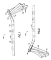
- a fracture fixation system 100 is shown.
- the system 100 shown and described is particularly adapted for aligning and stabilizing multiple bone fragments in a dorsally displaced distal radius fracture (or Colles' fracture), but the invention as described below is applicable to other surgical orthopedic bone stabilization systems for use in the treatment of this and other fractures.
- the system 100 generally includes a substantially rigid T-shaped plate 102 for distal radius fractures, commonly called a volar plate, which is preferably made from a titanium alloy, such as Ti-6Al-4V.
- the plate includes a body 116 and a head 118.
- the system 100 also includes bone screws 104 ( Fig. 3 ), a set of unidirectional locking screws 106, 108, and a set of surgeon-directed omnidirectional locking screws 400 (500, 600, 700, 800), described hereinafter.
- the body 116 includes four preferably countersunk screw holes 124, 125, 126, 127 for the extension of bone screws 104 therethrough ( Fig. 2 ).
- One of the screw holes, 127 is preferably generally oval in shape permitting longitudinal movement of the plate 102 relative to the shaft of a bone screw when the screw is not clamped against the plate.
- the screw holes may be any hole type used for attaching a fixation structure, either threaded or non-threaded, such that a cortical screw or a locking screw may be coupled relative to the plate and underlying bone.
- the head portion 118 includes a proximal first set of threaded preferably cylindrical threaded holes 134 (for placement of locking screws 106 and/or 108 therein) and a relatively distal second set of threaded preferably cylindrical threaded holes 138 (for placement of locking screw 106 and/or 108 therein).
- the threaded holes 134 of the first set are arranged substantially parallel to a line L 1 that is preferably slightly oblique (e.g., by 5°-10°) relative to a perpendicular to the longitudinal axis of the body portion 116.
- Axes through the first set of threaded holes are preferably oblique relative to each other, and are preferably angled relative to each other in two dimensions, generally as described in commonly-owned U.S. Pat. No. 6,364,882 .
- This orientation of the locking screws operates to stabilize and secure the head 118 of the plate 102 on the bone even where such locking screws 106 do not have threaded shafts.
- the second set of threaded holes 138 is provided relatively distal of the first set of threaded holes 134 and is most preferably primarily located in a buttress portion 120 of the plate.
- Each of the threaded holes 138 preferably defines an axis that is oblique relative to the other of threaded holes 136 and 138.
- each and every locking screw 106, 108 when positioned within respective threaded holes 134, 138 defines a distinct axis relative to the other locking screws.
- the axes of the threaded holes 138 are preferably oriented relative to the axes of threaded holes 134 such that locking screws 106, 108 within threaded holes 138 extend (or define axes which extend) between locking screws (or axes thereof) within threaded holes 134 in an interleaved manner.
- Locking screws 106 have a threaded head and a non-threaded shaft, and locking screws 108 have both a threaded head and at least a portion of the shaft is threaded. Exemplar locking screws are described in more detail in U.S. Pat. No. 6,364,882 . Either locking screws 106 or 108, or a combination thereof may be used at the discretion of the surgeon when the surgeon elects to implants unidirectional screws. As discussed in detail below, the surgeon may also opt to implant omnidirectional surgeon-directed screws 400 in place of any of the unidirectional screws 106, 108.
- axes through the first set of threaded holes 134 are preferably oblique relative to each other, and are preferably angled relative to each other in two dimensions, generally as described in commonly-owned U.S. Pat. No. 6,364,882 . More particularly, the axes of the holes 134 are angled so as to extend through the subchondral bone just below and parallel to the curving articular surface of the distal radius so that, in lateral view, unidirectional locking screws extending through the holes 134 provide support for the dorsal aspect of the subchondral bone. This oblique orientation of the locking screws operates to stabilize the dorsal aspects of the subchondral bone of the articular surface relative to the head 118 of the plate 102 even where such locking screws 106 do not have threaded shafts.
- the lateral and medial threaded holes of the first set of threaded holes 134 are for placement of locking screws intended to extend into the radial styloid and ulnar fragment of the distal radius bone. With respect to such holes it may be desired to angle the locking screws at a surgeon directed angle relative to the hole axis to facilitate the capture of corresponding bone fragments.
- the second set of holes 138 is provided relatively distal of the first set of holes 134 and is most preferably primarily located in a tapered supporting buttress portion 120 of the plate.
- Each of the holes 138 preferably defines an axis that is oblique relative to the other of holes 136 and 138.
- each and every locking screw 106, 108 when positioned within respective holes 134, 138 preferably defines a distinct non-parallel axis relative to the other locking screws.
- the axes of the holes 138 are preferably oriented relative to the axes of 134 such that locking screws 106, 108 within holes 138 extend (or define axes which extend) between locking screws (or axes thereof) within holes 134 in an interleaved manner which, in lateral view, defines a cradle that provides support for the central aspect of the subchondral bone of the distal radius.
- the oblique orientation of the locking screws provides such stabilization even where such locking screws 106 do not have threaded shafts.
- the axes of the holes 134, 138 of the plate are preferably oriented so that unidirectional screws inserted therein will provide the maximum support without necessitating deviation from the predefined axes.
- each of the holes 134, 138 of the plate 102 has an internal thread 312 that extends helically along the same characteristic direction (right-hand or left-handed).
- the internal thread 312 of each screw hole preferably has a cylindrical contour.
- Each unidirectional locking screw has a head 300 with an external thread 302 that extends helically in the same direction as the internal threads of the locking screw holes 134, 138 of the plate.
- the threads of the head 300 threadably engage with the preformed threads 312 of a given screw hole.
- the internal thread 312 and the external thread 302 preferably each have an 'angle of thread' of 60 degrees (as defined below).
- the unidirectional screw When secured in a given screw hole of the plate, the unidirectional screw extends from the plate 102 at a fixed angular orientation defined by a central axis through the helical threads of the given screw hole.
- the system 100 also includes the second set of locking screws 400 ( Figs. 8A-8C ) that are adapted to self-tap into the holes 134, 138 in a manner that allows the screws to be secured (e.g., fixed and "locked") at an arbitrary surgeon-directed angle with respect to the axis of the given locking screw hole.
- the angular orientation of the self-tapping locking screw which can be omnidirectional within a range, is dictated by the axial force applied by the surgeon to the screw while applying a rotational driving force for inserting the screws 400 into the holes 134, 138.
- self-tap self-tapping
- self-tappable are used herein to denote that the screw 400 is structured such that it is angularly locked into position against the internal thread of the hole by an interference fit and possibly deformation of the mating structures, rather than a conventional threaded engagement of two preformed threads of the same pitch.
- These self-tapping locking screws are used to stabilize the fractured bone in a manner similar to the unidirectional locking screws described above.
- these self-tapping locking screws provide the surgeon with flexibility, ease of use, and operational efficiency in employing either unidirectional locking screw fixation or surgeon-directed fixation within the same hole.
- the use of self-tapping locking screws permits the surgeon to modify the angle of approach of a fixator relative to the axes of screw holes which are already obliquely oriented relative to each other.
- substantially greater range of angular diversity between the screws 400 is possible than in the prior art.
- the maximum variation between two screws is 30°. If two screw holes already have axes angled 30° relative to each other, given a ⁇ 15° angular variation at any screw hole, the maximum variation between two screws is 60°.
- the self-tapping angular variation can be used for "fine-tuning" the angle of the screw, as opposed to gross selection of the angle.
- Figs. 8A - 8B illustrate a first example of a self-tapping locking screw 400.
- the self-tapping locking screw 400 includes a head 402 and a non-threaded shaft 404.
- the shaft 404 may be threaded (for example, in a manner similar to the shaft of screw 108).
- the head 402 includes a top surface 405 and an external thread 406.
- the top surface 405 includes a hole or slot (e.g., a square or hexagonal slot) or other structural feature (not shown) that mates to a driver that is used to forcibly insert and rotate the head 402 of the locking screw 400 into the screw hole to tap new threads.
- the hole is a square slot, optionally with edge breaks, that provides a substantially larger cross-sectional area (e.g., approximately 40% larger) than in a conventional locking screw of like head size, thereby providing increased surface area for application of higher torque force.
- the external thread 406 extends helically in the opposite direction relative to the internal threads of the locking screw holes 134, 136 of the plate 102.
- external thread 406 is referred to as "reverse-handed” or a "reverse-hand” thread.
- the profile of the thread 406 is conical in shape.
- Such a conical profile may be formed by the crest 408 and root 410 of the thread 406 both having a conical profile wherein the conical profile of the root 410 is offset radially inward and vertically with respect the conical profile of the crest 408.
- the dimensions of the reverse-hand thread 406 are selected such that the reverse-hand thread 406 self-taps into the internal thread of a screw hole (134, 138) of the plate 102 in a manner that allows the screw 400 to be secured at the directed angle relative to the axis of the given screw hole.
- the angular orientation of the screw 400 can be set to any angle ⁇ from 0 to ⁇ 15°.
- Fig. 8C illustrates another similar self-tapping locking screw 400a secured in place in the plate 102 at an angle ⁇ of 10° relative to the axis A of the screw hole.
- Differences between screws 400 ( Figs. 8A , 8B ) and 400a ( Fig. 8C ) include a non-threaded upper head portion 420a (which functions as a stop to limit how far the screw head can be tapped into the screw hole), a tapered neck 422a between the head and shaft portions, and an at least partially threaded shaft 404a (to lag bone fragments).
- the 'angle of thread' is a feature of a thread defined by the angle between adjacent flanks (i.e., the thread surface extending between the crest and root) measured at a cross-section of the thread.
- the angle of thread of the internal thread of the screw holes (134, 138) and the angle of thread of the reverse-handed external thread 406 of the screw 400 may be equal (or substantially similar) at approximately 60 degrees. These angles may be increased (for example, greater than 70 degrees and more preferably 75 degrees) for improved fixation. In alternate embodiments, these angles may be substantially different from one another.
- the reverse-handed external thread 406 of the screw 400 may comprise a two-start thread structure.
- a two-start thread structure is well known and generally includes a double helically thread design with the threads offset by 180°. This structure will overcome wobbling because the external threads on the screw head contact the internal thread of the screw hole on opposite sides of the head 402 with opposing diametric forces as the head 402 enters the threaded screw hole.
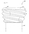
- Fig. 9 illustrates a second example of an omnidirectional locking screw 500 for use through threaded holes.
- the screw 500 includes a head 502 and a shaft 504 (which may be threaded or non-threaded).
- the head 502 includes a top surface 505 and an external thread 506.
- the top surface 505 includes a hole or slot (e.g., a square or hexagonal slot) or other structural feature (not shown) that mates to a driver that is used to forcibly insert and rotate the head 502 of the locking screw 500.
- the external thread 506 extends helically in the opposite direction relative to the internal threads of the screw holes (134, 138) of the plate 102.
- the profile of the thread 506 is spherical in shape.
- the dimensions of the reverse-hand thread 506 are selected such that the reverse-hand thread 506 self-taps into the internal thread of a screw hole (134, 138) of the plate 102 in a manner that allows the screw 500 to be secured (e.g., fixed) at an arbitrary angle within a range with respect to the axis of the given screw hole.
- the angle of thread of the internal thread of the screw holes (134, 138) and the angle of thread of the reverse-handed external thread 506 may be equal (or substantially similar) at an angle greater than 55 degrees, for example 60 degrees. These angles may be increased (for example, greater than 70 degrees and more preferably 75 degrees) for improved fixation. In alternate examples, these angles may be substantially different from one another.
- the reverse-handed external thread 506 of the self-tapping locking screw 500 may comprise a two-start thread structure, as described above. This structure will overcome wobbling because the screw head applies contacts to the internal thread of the screw hole on opposite sides of the head 502 with opposing diametric forces as the head 502 enters the screw hole.
- the spherical profile of the thread 506 of the locking screw 500 provides a longer length of engagement that the conical profile of the thread 406 of the screw 400.
- the conical profile locks quicker than the spherical profile.
- Fig. 10 another example of a surgeon directed locking screw system is shown.
- the self-tapping external structure of the head of each surgeon-directed screw of the first set is realized by external threads 606 that runs in the same direction as the internal threads 312 of the threaded holes 134, 138 of the plate 102; for example, right-hand external threads on the screw head for insertion through a right-hand threaded screw hole.
- Such external and internal threads are preferably, though not necessarily of significantly different pitch from each other. If of a different pitch, the threads purposefully cross-thread providing an interference fit.
- the external threads 606 may have a lesser angle of attack against the plate threads than the reverse thread screws.
- the external and internal threads 606, 312 can be in the same and even have the same pitch and be made to cross thread by virtue of the angle of insertion.
- the head 602 of the screw 600 preferably has a conical (as indicated by broken lines) or spherical profile.
- Locking screw 800 is made of a cobalt chrome (CoCr) alloy, e.g., Co-28Cr-6Mb for insertion into a plate made of titanium alloy, e.g., Ti-6Al-4V.
- CoCr cobalt chrome
- the locking screw 800 includes a head 800 that is 2.5 mm in diameter, that is tapered by 8°, that has threads 806 with an angle of thread at 90° (for internal threads with angle of thread at 60°), and that has two-start threads at 180° apart.
- the larger angle of thread requires more torque to insert the screw. Therefore, the driver slot 810 at the rear of the head 802 is a relatively larger square slot facilitating a relatively larger manual application of torque to the locking screw and the stability of the locking screw on the driver.
- the large slot is possible because of the increased strength of the CoCr alloy (ultimate strength 203,000 ksi) relative to the conventional unidirectional screw material of Ti alloy (ultimate strength 138,000 ksi).
- the approximately 50% increase in strength permits the area of the head surrounding the square slot to be approximately 20-30% thinner and maintain at least the same strength as a conventional unidirectional screw.
- the tapered head achieves directional mobility during insertion and permits three complete turns of threads to be located on the head (as opposed to two turns for a conventional locking screw), the large angle of thread removes more material from the thread hole providing more interference between the screw and hole, the two-start thread provides stability during non-axial insertion, and the driver slot allows sufficiently larger force to be applied to the locking screw.
- using the relatively larger square slot enables a comfortable manual application of 5-7 in/lb to the locking screw (in distinction from 2-3 in/lb with a smaller conventional square slot).
- the proximal portion 812 of the head is rounded and less than 1 mm protrudes above the plate when fully inserted, thus providing an atraumatic profile to the surrounding soft tissue when in use.
- the CoCr alloy is significantly stronger, harder, and stiffer than titanium alloy.
- a portion 814 of the shaft 804 of locking screw is reduced in diameter (relative to the corresponding diameter of the titanium alloy locking screw).
- the diameter of the shaft of the screw is reduced (by step or gradually) from 0.078 inch to 0.064 inch to substantially mimic the flexibility of the titanium unidirectional locking screws when loaded axially. It is preferable that such reduction 814 occur spaced below the threads 806 of the head 802 (e.g., preferably at least 2 mm below), so that relatively adjacent the plate the shaft 804 of surgeon-directed locking screw is well-adapted to transfer shear loads to the plate, and spaced upwards from any threads on the shaft.
- the distal end of the shaft may be provided with threads 816 for lag functionality. As such, the pitch of such threads is preferably substantially the same as the pitch of threads 806.
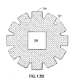
- Figs. 13A and 13B illustrate a fourth embodiment of an omnidirectional screw 700 in accordance with the present invention.
- the screw 700 includes a head 702 and a shaft 704 (which may be threaded or non-threaded).
- the head 702 includes a top surface 705 and a set of external ridges 706 and external grooves 707 that are radially spaced apart from one another about the outer circumference of the head 702 and that extend in vertical directions substantially parallel to the central axis of the screw 700 as shown.
- the profile of the ridges 705 is preferably spherical in shape as shown; however, a conical profile or other suitable profile may be used.
- the dimensions of the ridges 705 and grooves 706 are selected such that the ridges 705 are deformed by the internal thread of a screw hole (134, 138) of the plate 702 in a manner that allows the screw 700 to be secured at an arbitrary angle within a range with respect to the axis of the given screw hole. Similar to the operation of the screw 400 of Figs. 8A-8B , the angular orientation of the screw 700 is dictated by the axial direction of the insertion force applied to the head 702 by the surgeon during forcible insertion and rotation of the head 702 during the surgical operation.
- Fig. 13B shows the ridges 706 and grooves 707 spaced apart from one another about the outer circumference of the head 702. It also shows a square hole 708 that mates to a driver that is used to forcibly insert and rotate the head 702 of the locking screw 700.
- the ridges 706 may have a variable width along their extent in the vertical direction with their greatest width at top and narrowest width near the bottom of the head 702 as shown in Fig. 13A .
- the ridges 706 may have a constant width along their extent in the vertical direction.
- the material of the external contact structure (e.g., reverse-handed external thread, same hand external thread of same or dissimilar pitch, or external ridges) of the self-tapping locking screw may be harder than the material of the internal threads of the locking screw holes of the plate, as described above with respect to one exemplar embodiment wherein the locking screw is made of CoCr alloy and the plate is made of Ti alloy. Other metal or metal alloy combinations of harder and softer metals can also be used.
- the internal threads of the locking screw holes may be non-anodized while the external contact structures of the locking screw are anodized, but otherwise of the same material.
- Such non-anodized internal threads may be realized by anodizing the plate 102 before drilling and tapping the threads of the screw holes therein.
- the screw hole internal thread is preferably harder than the structure (e.g., ridges) on the screw head which are intended to be deformed.
- the external contact structure cut into the plate because of geometrical configurations of the threads.
- the internal plate threads can be made relatively weaker than the screw threads by providing a relatively more acute cross section apical angle to the internal threads than the peg threads.
- the external screw threads can be trapezoidal in cross section providing greater strength by geometrical means in addition to or as opposed to being made of a harder material.
- the top part of head of the screws are preferably wider than the width of the threaded screw holes 134, 138 of the plate 102 to ensure that the heads of the screws bottom out against the surface of the plate 102 (i.e., to prevent the omnidirectional screws from being inserted completely through the threaded screw hole).
- omnidirectional self-tapping locking screws described herein are used to stabilize a fractured bone in a manner similar to the unidirectional locking screws described above.
- the same holes in the fixation plate can support both unidirectional or omnidirectional screws.
- the surgeon is afforded flexibility, ease of use, and operational efficiency.
- the omnidirectional self-tapping screws described herein are inexpensive to manufacture and provide for effective fixation at minimal costs.
- one or both sets of the locking screw may be replaced by preferably blunt tines which are integrated into the plate such that the plate and tines are unitary in construct.
- other elongate projections may be coupled to the plate to define the desired support.
- the system may also include K- wires 110, and K- wire alignment holes 140, 152a, 152b, 152c, 154 in the plate 102 ( Figs. 1-6 ).
- K- wires 110 through K-wire alignment holes and the advantage thereof is described in detail in co-owned U.S. Pat. No. 7,282,053 .
- a bone fixation plate and particularly plates for fixation of distal radius fractures . While particular embodiments of the invention have been described, it is not intended that the invention be limited thereto, as it is intended that the invention be as broad in scope as the art will allow and that the specification be read likewise. Thus, while particular preferred materials, dimensions, and relative angles for particular elements of the system have been disclosed, it will be appreciated that other materials, dimensions, and relative angles may be used as well. Further, plates having shapes other than a 'T' may also be used, such as straight plates, lateral and medial columns (generally 'L'-shaped), flared head plates, forked plates, etc.
- fixation plate system of the present invention utilizes cylindrical locking screw holes that are compatible with both the threaded head interface for unidirectional locking screw as well as the reverse-hand threaded, same-hand threaded, or ridged head interface for omnidirectional locking screw, it will be appreciated that the invention can be readily extended to incorporate other compatible interface mechanisms.
- different thread designs such as double or triple threads, can be used for the locking threads of the locking screw holes, unidirectional locking screw and the omnidirectional locking screw.
Claims (11)
- Système de fixation d'os (100), comprenant :une plaque sensiblement rigide (102) ayant une surface venant en contact avec l'os et définissant un ensemble de trous de vis (134, 138) avec des filetages internes (312), lesdits filetages internes (312) desdits trous de vis (134, 138) définissant des axes de trou de vis respectifs ;un ensemble d'un premier type de vis de verrouillage (800), chaque premier type respectif de vis de verrouillage ayant une tête (802) avec un filetage externe (806) qui s'auto-taraude dans le filetage interne (312) d'un trou de vis de verrouillage donné (134, 138) suivant un angle oblique relativement audit axe de trou de vis respectif pour fixer ledit premier type de vis de verrouillage (800) à ladite plaque (102) ; etun ensemble d'un deuxième type de vis de verrouillage de fixation (106, 108), chaque deuxième type respectif de vis de verrouillage de fixation ayant une tête (300) avec un filetage externe (302) qui est apte à venir en prise de filetage avec le filetage interne (312) d'un trou de vis donné (134, 138), pour fixer le deuxième type respectif de vis de verrouillage de fixation (106, 108) à un angle fixe relativement à ladite plaque (102) en alignement avec l'axe de trou de vis respectif ;où ladite plaque (102) est réalisée en un premier métal d'une première dureté, ledit premier type de vis de verrouillage (800) sont réalisées en un deuxième métal différent d'une deuxième dureté sensiblement plus dure que ladite première dureté, et lesdites vis de verrouillage de fixation du deuxième type (106, 108) sont réalisées avec ledit premier métal ;où lesdites vis de verrouillage du premier type (800) comprennent chacune un arbre (804), une portion (814) dudit arbre (804) espacée de ladite tête (802) et une extrémité opposée de ladite vis (800) est réduite en diamètre ; etoù la portion d'un diamètre réduit (814) dudit premier type de vis de verrouillage (800) est sélectionnée de telle sorte que lesdites vis de verrouillage du premier type (800) ne sont pas moins flexibles que lesdites vis de verrouillage du deuxième type (106, 108).
- Système de fixation d'os (100) selon la revendication 1, dans lequel ledit premier métal est un alliage de titane, et ledit deuxième métal est un alliage de cobalt chrome.
- Système de fixation d'os (100) selon la revendication 1, dans lequel ledit filetage externe (806) et ledit filetage interne (312) sont enroulés dans une même direction.
- Système de fixation d'os (100) selon la revendication 1, dans lequel pour ledit premier type de vis de verrouillage (800), ledit filetage externe (806) a un angle de filetage d'approximativement 90°.
- Système de fixation d'os (100) selon la revendication 1, dans lequel pour ledit premier type de vis de verrouillage (800), ladite tête (802) est effilée selon approximativement 8°.
- Système de fixation d'os (100) selon la revendication 1, dans lequel pour ledit premier type de vis de verrouillage (800), ladite tête (802) est pourvue de filetages à deux débuts (806).
- Système de fixation d'os (100) selon la revendication 1, dans lequel ledit arbre (804) dudit premier type de vis de verrouillage (800) est pourvu de filetages distaux aptes à venir en prise avec l'os (816), et ladite portion (814) réduite en diamètre se situe entre ladite tête (802) et lesdits filetages distaux (816).
- Système de fixation d'os (100) selon la revendication 1, dans lequel lesdits premier type (800) et deuxième type (106, 108) de vis de verrouillage de fixation ont chacun des fentes de driver (810), lesdites fentes de driver (810) dudit premier type (800) ayant une aire plus grande en section transversale que lesdites fentes de driver dudit deuxième type (106, 108).
- Système de fixation d'os (100) selon la revendication 1, dans lequel au moins deux desdits axes de trou de vis sont obliques l'un relativement à l'autre.
- Système de fixation d'os (100) selon la revendication 9, dans lequel au moins deux desdits axes de trou de vis sont obliques dans deux dimensions l'un relativement à l'autre.
- Système de fixation d'os (100) selon la revendication 2, dans lequel :ladite tête (802) de chaque vis de cobalt chrome (800) est effilée et inclut des filetages externes à deux débuts (806) commençant de manière espacée de 180 ;ledit arbre (804) de chaque vis de cobalt chrome (800) possède une portion non filetée adjacente à ladite tête (802), et une portion filetée avec des filetages venant en prise avec l'os (816) adjacente à une extrémité opposée de l'arbre (804), la portion de diamètre réduit (814) étant espacée de et située entre à la fois ladite tête (802) et ladite portion filetée de ladite vis (800).
Applications Claiming Priority (2)
| Application Number | Priority Date | Filing Date | Title |
|---|---|---|---|
| US11/384,773 US7905909B2 (en) | 2005-09-19 | 2006-03-20 | Bone stabilization system including multi-directional threaded fixation element |
| PCT/US2007/063642 WO2007109436A2 (fr) | 2006-03-20 | 2007-03-09 | Système de stabilisation d'os incluant un élément de fixation fileté multi-directionnel |
Publications (3)
| Publication Number | Publication Date |
|---|---|
| EP1996120A2 EP1996120A2 (fr) | 2008-12-03 |
| EP1996120A4 EP1996120A4 (fr) | 2011-06-15 |
| EP1996120B1 true EP1996120B1 (fr) | 2015-07-01 |
Family
ID=38523150
Family Applications (1)
| Application Number | Title | Priority Date | Filing Date |
|---|---|---|---|
| EP07758216.1A Not-in-force EP1996120B1 (fr) | 2006-03-20 | 2007-03-09 | Système de stabilisation d'os incluant un élément de fixation fileté multi-directionnel |
Country Status (7)
| Country | Link |
|---|---|
| US (1) | US7905909B2 (fr) |
| EP (1) | EP1996120B1 (fr) |
| JP (1) | JP5101597B2 (fr) |
| AU (1) | AU2007227098B2 (fr) |
| CA (1) | CA2647067C (fr) |
| WO (1) | WO2007109436A2 (fr) |
| ZA (1) | ZA200808914B (fr) |
Cited By (2)
| Publication number | Priority date | Publication date | Assignee | Title |
|---|---|---|---|---|
| US9480512B2 (en) | 2000-02-01 | 2016-11-01 | Biomet C.V. | Volar fixation system with fixed-angle multi-hole drill guide |
| US9510880B2 (en) | 2013-08-13 | 2016-12-06 | Zimmer, Inc. | Polyaxial locking mechanism |
Families Citing this family (108)
| Publication number | Priority date | Publication date | Assignee | Title |
|---|---|---|---|---|
| US8518090B2 (en) | 2010-10-05 | 2013-08-27 | Acumed Llc | Fastener with serrated thread for attachment to a bone plate at a selectable angle |
| US20040111090A1 (en) * | 2002-10-03 | 2004-06-10 | The University Of North Carolina At Chapel Hill | Modification of percutaneous intrafocal plate system |
| US7951176B2 (en) | 2003-05-30 | 2011-05-31 | Synthes Usa, Llc | Bone plate |
| DE20321552U1 (de) | 2003-08-26 | 2007-12-27 | Synthes Gmbh | Knochenplatte |
| US11259851B2 (en) | 2003-08-26 | 2022-03-01 | DePuy Synthes Products, Inc. | Bone plate |
| US7635365B2 (en) | 2003-08-28 | 2009-12-22 | Ellis Thomas J | Bone plates |
| US8574268B2 (en) | 2004-01-26 | 2013-11-05 | DePuy Synthes Product, LLC | Highly-versatile variable-angle bone plate system |
| US7637928B2 (en) * | 2004-01-26 | 2009-12-29 | Synthes Usa, Llc | Variable angle locked bone fixation system |
| US11291484B2 (en) | 2004-01-26 | 2022-04-05 | DePuy Synthes Products, Inc. | Highly-versatile variable-angle bone plate system |
| US8029551B2 (en) * | 2006-01-10 | 2011-10-04 | Running Donald E | Fracture fixation plate with cover sheath |
| US8021402B2 (en) * | 2006-03-07 | 2011-09-20 | Orthohelix Surgical Designs, Inc. | Distal radius plate |
| US8926675B2 (en) * | 2006-04-11 | 2015-01-06 | Biomet Manufacturing, Llc | Contoured bone plate |
| US20100137996A1 (en) | 2007-05-01 | 2010-06-03 | Moximed, Inc. | Femoral and tibial base components |
| US9907645B2 (en) | 2007-05-01 | 2018-03-06 | Moximed, Inc. | Adjustable absorber designs for implantable device |
| US8894714B2 (en) | 2007-05-01 | 2014-11-25 | Moximed, Inc. | Unlinked implantable knee unloading device |
| US7678147B2 (en) | 2007-05-01 | 2010-03-16 | Moximed, Inc. | Extra-articular implantable mechanical energy absorbing systems and implantation method |
| US20080275567A1 (en) | 2007-05-01 | 2008-11-06 | Exploramed Nc4, Inc. | Extra-Articular Implantable Mechanical Energy Absorbing Systems |
| US20110245928A1 (en) | 2010-04-06 | 2011-10-06 | Moximed, Inc. | Femoral and Tibial Bases |
| US8100967B2 (en) | 2007-05-01 | 2012-01-24 | Moximed, Inc. | Adjustable absorber designs for implantable device |
| US9655648B2 (en) | 2007-05-01 | 2017-05-23 | Moximed, Inc. | Femoral and tibial base components |
| US8425616B2 (en) | 2007-07-09 | 2013-04-23 | Moximed, Inc. | Surgical implantation method and devices for an extra-articular mechanical energy absorbing apparatus |
| US7846211B2 (en) | 2007-07-09 | 2010-12-07 | Moximed, Inc. | Surgical implantation method and devices for an extra-articular mechanical energy absorbing apparatus |
| US7632310B2 (en) | 2007-07-09 | 2009-12-15 | Moximed, Inc. | Surgical implantation method and devices for an extra-articular mechanical energy absorbing apparatus |
| US8262706B2 (en) | 2007-07-11 | 2012-09-11 | Stryker Trauma Gmbh | Device for creating a bone implant |
| EP2397083B1 (fr) | 2007-11-02 | 2014-05-07 | Biomet C.V. | Système de fixation de fracture du coude |
| US8317842B2 (en) | 2007-11-30 | 2012-11-27 | Biomet C.V. | Distal tibia plating system |
| US8287538B2 (en) | 2008-01-14 | 2012-10-16 | Conventus Orthopaedics, Inc. | Apparatus and methods for fracture repair |
| US8262707B2 (en) | 2008-07-31 | 2012-09-11 | Biomet C.V. | Periarticular bone plate with biplanar offset head member |
| US8257405B2 (en) * | 2008-07-31 | 2012-09-04 | Biomet C.V. | Periarticular bone plate with biplanar offset head member |
| US8784458B1 (en) | 2008-10-10 | 2014-07-22 | Greatbatch Medical S.A. | Polyaxial insert for surgical screws |
| US8906076B2 (en) | 2008-10-17 | 2014-12-09 | Osteomed Llc | Angulated locking plate and screw |
| US8597334B2 (en) * | 2008-10-17 | 2013-12-03 | Osteomed Llc | Angulated locking plate/screw interface |
| US9301785B2 (en) * | 2008-10-21 | 2016-04-05 | K2M, Inc. | Spinal buttress plate |
| WO2011075757A1 (fr) * | 2008-12-23 | 2011-06-30 | Austofix Group Pty Ltd | Eléments de fixation pour plaques de fixation |
| FR2941859B1 (fr) | 2009-02-09 | 2012-04-06 | Memometal Technologies | Vis d'osteosynthese. |
| US8246664B2 (en) * | 2009-02-24 | 2012-08-21 | Osteomed Llc | Multiple bone fusion plate |
| US8529608B2 (en) | 2009-04-28 | 2013-09-10 | Osteomed Llc | Bone plate with a transfixation screw hole |
| US9259255B2 (en) | 2009-07-15 | 2016-02-16 | Orthohelix Surgical Designs, Inc. | Variable axis locking mechanism for use in orthopedic implants |
| US9095444B2 (en) | 2009-07-24 | 2015-08-04 | Warsaw Orthopedic, Inc. | Implant with an interference fit fastener |
| US9861408B2 (en) | 2009-08-27 | 2018-01-09 | The Foundry, Llc | Method and apparatus for treating canine cruciate ligament disease |
| US10349980B2 (en) | 2009-08-27 | 2019-07-16 | The Foundry, Llc | Method and apparatus for altering biomechanics of the shoulder |
| US8597362B2 (en) | 2009-08-27 | 2013-12-03 | Cotera, Inc. | Method and apparatus for force redistribution in articular joints |
| US9278004B2 (en) | 2009-08-27 | 2016-03-08 | Cotera, Inc. | Method and apparatus for altering biomechanics of the articular joints |
| US9668868B2 (en) | 2009-08-27 | 2017-06-06 | Cotera, Inc. | Apparatus and methods for treatment of patellofemoral conditions |
| US8758346B2 (en) * | 2009-09-14 | 2014-06-24 | DePuy Synthes Products, LLC | Variable angle compression plate |
| EP2477573B1 (fr) * | 2009-09-18 | 2015-07-01 | Biomet C.V. | Trousse jetable pour chirurgie orthopédique et composants associés |
| US10390867B2 (en) | 2009-09-18 | 2019-08-27 | Biomet C.V. | Bone plate system and method |
| US8496692B2 (en) * | 2009-09-21 | 2013-07-30 | Jmea Corporation | Locking securing member |
| CN102596073B (zh) * | 2009-11-17 | 2015-09-23 | 新特斯有限责任公司 | 可变角度锁定支撑栓 |
| US8568417B2 (en) | 2009-12-18 | 2013-10-29 | Charles River Engineering Solutions And Technologies, Llc | Articulating tool and methods of using |
| US8486116B2 (en) | 2010-01-08 | 2013-07-16 | Biomet Manufacturing Ring Corporation | Variable angle locking screw |
| US20110178520A1 (en) | 2010-01-15 | 2011-07-21 | Kyle Taylor | Rotary-rigid orthopaedic rod |
| CN105534561B (zh) | 2010-01-20 | 2018-04-03 | 康文图斯整形外科公司 | 用于骨接近和骨腔准备的装置及方法 |
| AU2011224529C1 (en) | 2010-03-08 | 2017-01-19 | Conventus Orthopaedics, Inc. | Apparatus and methods for securing a bone implant |
| US20110218580A1 (en) * | 2010-03-08 | 2011-09-08 | Stryker Trauma Sa | Bone fixation system with curved profile threads |
| US9113970B2 (en) * | 2010-03-10 | 2015-08-25 | Orthohelix Surgical Designs, Inc. | System for achieving selectable fixation in an orthopedic plate |
| US8647371B2 (en) * | 2010-04-30 | 2014-02-11 | Globus Medical, Inc. | Locking bone screws and methods of use thereof |
| US8603148B2 (en) | 2010-05-07 | 2013-12-10 | Raymond B. Raven, III | System for treating bone fractures |
| US20130138156A1 (en) * | 2010-09-02 | 2013-05-30 | Neosteo | Osteosynthesis device |
| US8728129B2 (en) | 2011-01-07 | 2014-05-20 | Biomet Manufacturing, Llc | Variable angled locking screw |
| USRE45714E1 (en) * | 2011-02-03 | 2015-10-06 | Normed Medizin-Technik Gmbh | Hand implant |
| WO2012112327A2 (fr) | 2011-02-14 | 2012-08-23 | Skeletal Dynamics, L.L.C. | Plaque de fixation de fracture |
| US9044270B2 (en) | 2011-03-29 | 2015-06-02 | Moximed, Inc. | Apparatus for controlling a load on a hip joint |
| WO2013049849A2 (fr) | 2011-09-30 | 2013-04-04 | Acute Innovations, Llc, An Oregon Limited Liability Company | Système de fixation osseuse ayant des parties de montage opposées |
| EP2614787B1 (fr) * | 2012-01-16 | 2017-03-15 | Carbofix Orthopedics Ltd. | Fixation d'une plaque osseuse multi-axiale |
| WO2013113015A1 (fr) | 2012-01-26 | 2013-08-01 | Acute Innovations Llc | Pince pour stabilisation de côte |
| CN104507405B (zh) * | 2012-05-22 | 2017-06-27 | 奥斯托费克斯集团有限公司 | 骨固定装置 |
| US9387022B2 (en) | 2012-06-27 | 2016-07-12 | DePuy Synthes Products, Inc. | Variable angle bone fixation device |
| US9265542B2 (en) * | 2012-06-27 | 2016-02-23 | DePuy Synthes Products, Inc. | Variable angle bone fixation device |
| JP5960546B2 (ja) * | 2012-08-16 | 2016-08-02 | ミズホ株式会社 | 骨折治療用プレート |
| US9468466B1 (en) | 2012-08-24 | 2016-10-18 | Cotera, Inc. | Method and apparatus for altering biomechanics of the spine |
| US9687284B2 (en) | 2013-02-13 | 2017-06-27 | Stryker European Holdings I, Llc | Locking peg with extended thread |
| US9103367B2 (en) | 2013-03-14 | 2015-08-11 | Imds Llc | Polyaxial locking interface |
| US9404525B2 (en) | 2013-03-14 | 2016-08-02 | Imds Llc | Polyaxial locking interface |
| US9468479B2 (en) | 2013-09-06 | 2016-10-18 | Cardinal Health 247, Inc. | Bone plate |
| US9833270B2 (en) | 2013-09-19 | 2017-12-05 | Mcginley Engineered Solutions, Llc | Variable angle blade plate system and method |
| ITMI20131796A1 (it) * | 2013-10-29 | 2015-04-30 | Massimo Zanna | Impianto dentale |
| AU2014362251B2 (en) | 2013-12-12 | 2019-10-10 | Conventus Orthopaedics, Inc. | Tissue displacement tools and methods |
| US9987061B2 (en) * | 2014-01-28 | 2018-06-05 | Biomet C.V. | Implant with suspended locking holes |
| CN104287820A (zh) * | 2014-10-16 | 2015-01-21 | 常州市康辉医疗器械有限公司 | 一种具有万向锁定功能的钢板螺钉系统 |
| GB2532721B (en) | 2014-11-21 | 2021-02-10 | Everost Uk Ltd | Bone fixation plate |
| US10245088B2 (en) | 2015-01-07 | 2019-04-02 | Treace Medical Concepts, Inc. | Bone plating system and method |
| US10245086B2 (en) | 2015-02-18 | 2019-04-02 | Treace Medical Concepts, Inc. | Bone plating kit for foot and ankle applications |
| US20160278824A1 (en) * | 2015-03-25 | 2016-09-29 | Medartis Holding Ag | Method for treating fractures of a bone |
| US10238438B2 (en) | 2015-04-22 | 2019-03-26 | Flower Orthopedics Corporation | Proximal humeral fracture plate |
| USD816840S1 (en) * | 2015-04-22 | 2018-05-01 | Flower Orthopedics Corporation | Proximal humeral fracture plate |
| CN108882952B (zh) * | 2015-12-15 | 2021-03-09 | 穆罕默德·R·马赫福兹 | 股骨基板全髋关节置换术 |
| US11197701B2 (en) * | 2016-08-17 | 2021-12-14 | Globus Medical, Inc. | Stabilization systems |
| US11213327B2 (en) * | 2016-08-17 | 2022-01-04 | Globus Medical, Inc. | Fracture plates, systems, and methods |
| US10624686B2 (en) | 2016-09-08 | 2020-04-21 | DePuy Synthes Products, Inc. | Variable angel bone plate |
| US10905476B2 (en) | 2016-09-08 | 2021-02-02 | DePuy Synthes Products, Inc. | Variable angle bone plate |
| US10820930B2 (en) | 2016-09-08 | 2020-11-03 | DePuy Synthes Products, Inc. | Variable angle bone plate |
| USD811594S1 (en) * | 2016-10-05 | 2018-02-27 | Osteomed Llc | Harp wrist plate design |
| USD803402S1 (en) * | 2016-10-05 | 2017-11-21 | Osteomed Llc | Harp wrist plate design |
| US10631881B2 (en) | 2017-03-09 | 2020-04-28 | Flower Orthopedics Corporation | Plating depth gauge and countersink instrument |
| WO2019010252A2 (fr) | 2017-07-04 | 2019-01-10 | Conventus Orthopaedics, Inc. | Appareil et méthodes de traitement d'os |
| WO2019074798A1 (fr) | 2017-10-09 | 2019-04-18 | Acumed Llc | Système et méthode de fixation osseuse à l'aide d'un clou verrouillé à un ancrage encerclant |
| JP6980970B2 (ja) * | 2018-01-26 | 2021-12-15 | メイラ株式会社 | 骨治療用具、骨用ねじおよび骨用プレート |
| EP3533403B1 (fr) | 2018-03-02 | 2022-08-17 | Stryker European Holdings I, LLC | Plaques osseuses et vis associées |
| US11446067B2 (en) * | 2018-03-02 | 2022-09-20 | The Board Of Regents Of The University Of Nebraska | Distal radius plating system |
| US11026727B2 (en) | 2018-03-20 | 2021-06-08 | DePuy Synthes Products, Inc. | Bone plate with form-fitting variable-angle locking hole |
| US10772665B2 (en) | 2018-03-29 | 2020-09-15 | DePuy Synthes Products, Inc. | Locking structures for affixing bone anchors to a bone plate, and related systems and methods |
| US11013541B2 (en) | 2018-04-30 | 2021-05-25 | DePuy Synthes Products, Inc. | Threaded locking structures for affixing bone anchors to a bone plate, and related systems and methods |
| US11583323B2 (en) | 2018-07-12 | 2023-02-21 | Treace Medical Concepts, Inc. | Multi-diameter bone pin for installing and aligning bone fixation plate while minimizing bone damage |
| US10925651B2 (en) * | 2018-12-21 | 2021-02-23 | DePuy Synthes Products, Inc. | Implant having locking holes with collection cavity for shavings |
| WO2021010913A1 (fr) * | 2019-07-18 | 2021-01-21 | Efa Veterinerlik Hizmetleri Tic. Ltd. Sti. | Plaque distale à verrouillage poly-axial pour radius entièrement anatomique conçue pour des quadrupèdes |
| US11890039B1 (en) | 2019-09-13 | 2024-02-06 | Treace Medical Concepts, Inc. | Multi-diameter K-wire for orthopedic applications |
| WO2023240320A1 (fr) * | 2022-06-17 | 2023-12-21 | Field Orthopaedics Pty Ltd | Plaque et système de fixation osseuse |
Family Cites Families (240)
| Publication number | Priority date | Publication date | Assignee | Title |
|---|---|---|---|---|
| US388000A (en) | 1888-08-14 | Half to chaeles h | ||
| US472913A (en) * | 1892-04-12 | Nail or spike | ||
| US1151861A (en) | 1914-05-23 | 1915-08-31 | Ernest M Brumback | Countersinking screw-head. |
| US2056688A (en) | 1934-11-15 | 1936-10-06 | Lamson & Sessions Co | Weather-tight bolt |
| US2500370A (en) * | 1947-06-30 | 1950-03-14 | Mckibbin Genevieve | Repair of femur fracture |
| US2526959A (en) | 1947-07-01 | 1950-10-24 | Frank A Lorenzo | Fracture reduction apparatus |
| US3025853A (en) * | 1958-07-07 | 1962-03-20 | Christopher A Mason | Fixation device for fractured femur |
| US3236141A (en) * | 1963-11-05 | 1966-02-22 | Robert D Smith | Screw |
| USRE28841E (en) | 1966-06-22 | 1976-06-08 | Synthes A.G. | Osteosynthetic pressure plate construction |
| US3645161A (en) * | 1969-11-18 | 1972-02-29 | Pic Design Corp | Solder tip setscrew |
| US3709218A (en) * | 1970-04-24 | 1973-01-09 | W Halloran | Combination intramedullary fixation and external bone compression apparatus |
| US3717146A (en) * | 1971-02-01 | 1973-02-20 | W Halloran | Threaded intramedullary compression and fixation device |
| US3741205A (en) | 1971-06-14 | 1973-06-26 | K Markolf | Bone fixation plate |
| FR2233973A1 (en) | 1973-06-25 | 1975-01-17 | Chatin Robert | Osteosynthesis plate for femoral fracture surgery - has anchoring holes in ablong flat portion and widened blade |
| US3842825A (en) | 1973-11-12 | 1974-10-22 | R Wagner | Hip fixation device |
| GB1515293A (en) * | 1974-05-29 | 1978-06-21 | Nat Res Dev | Endoprosthetic devices |
| GB1571713A (en) | 1976-04-21 | 1980-07-16 | Gil J L | Apparatus for use in the treatment of bone fractures |
| US4011863A (en) * | 1976-07-19 | 1977-03-15 | Zickel Robert E | Supracondylar prosthetic nail |
| ZA771690B (en) * | 1977-04-21 | 1978-06-28 | C Grobbelaar | Improved hip joint |
| US4135507A (en) * | 1977-05-20 | 1979-01-23 | Harris Leslie J | Condylocephalic nail for fixation of pertrochanteric fractures |
| FR2405062A1 (fr) | 1977-10-10 | 1979-05-04 | Dayan Robert | Plaques d'osteosynthese destinees au traitement chirurgical des fractures de l'extremite inferieure du femur |
| US4169470A (en) | 1977-10-19 | 1979-10-02 | Ender Hans G | Surgical nail for use in setting bone fractures, and tool for emplacing same |
| US4172452A (en) | 1978-05-15 | 1979-10-30 | Howmedica, Inc. | Fracture nail plate assembly |
| AT366254B (de) | 1979-12-14 | 1982-03-25 | Ender Josef | Instrumentarium zur reposition und fixation von per- und subtrochanteren frakturen sowie einen teil dieses instrumentariums bildendes einsatzstueck |
| CH645013A5 (de) | 1980-04-14 | 1984-09-14 | Wenk Wilh Ag | Osteosynthetische kompressionsplatte. |
| CH648197A5 (de) | 1980-05-28 | 1985-03-15 | Synthes Ag | Implantat und zu dessen befestigung an einem knochen dienende schrauben. |
| CH651192A5 (de) * | 1980-11-20 | 1985-09-13 | Synthes Ag | Osteosynthetische vorrichtung und dazu passende bohrlehre. |
| ES272906Y (es) * | 1981-06-18 | 1984-12-16 | Mecron Medizinische Produkte Gmbh | Dispositivo de clavo para la fijacion de una fractura de femur. |
| SE424139B (sv) | 1981-07-17 | 1982-07-05 | Lars Kolmert | Anordning for sammankoppling av fjederspik och tverskruv vid fixation av benfrakturer |
| FR2519857A1 (fr) | 1982-01-19 | 1983-07-22 | Butel Jean | Dispositif pour osteosynthese des fractures des extremites du femur |
| DE8214493U1 (de) | 1982-05-18 | 1982-09-09 | Howmedica International, Inc. Zweigniederlassung Kiel, 2301 Schönkirchen | Knochennagel zur Versorgung von Frakturen im proximalen Oberschenkelbereich |
| FR2527921A1 (fr) | 1982-06-02 | 1983-12-09 | Tornier Sa | Perfectionnements aux clous pour l'osteosynthese des fractures de cols femoraux |
| AT378324B (de) * | 1982-09-13 | 1985-07-25 | Streli Elke | Zinkenplatte zur gegenseitigen lagefixierung der knochenteile bei knochenbruechen |
| CH662936A5 (de) * | 1984-05-18 | 1987-11-13 | Technomed Gmk | Knochenverbindungsplatte. |
| RO89820B1 (ro) * | 1985-11-05 | 2002-06-28 | îNTREPRINDEREA INDUSTRIA TEHNICO MEDICALA | Implanturi elastice, pentru osteosinteza elastica stabila, a fracturilor femurului si, respectiv, tibiei, precum si instrumentar de lucru |
| SE460014B (sv) * | 1986-01-31 | 1989-09-04 | John Stefan Nilsson | Fixationsanordning foer laarbensfrakturer |
| PL147580B1 (en) | 1986-04-14 | 1989-06-30 | Plate for uniting epiphysis and diaphysis of broken bone | |
| US4733654A (en) * | 1986-05-29 | 1988-03-29 | Marino James F | Intramedullar nailing assembly |
| US5190544A (en) * | 1986-06-23 | 1993-03-02 | Pfizer Hospital Products Group, Inc. | Modular femoral fixation system |
| US4776330A (en) | 1986-06-23 | 1988-10-11 | Pfizer Hospital Products Group, Inc. | Modular femoral fixation system |
| AT387711B (de) * | 1986-07-15 | 1989-03-10 | David Thomas | Knochenfixationsplatte |
| US4905680A (en) | 1986-10-27 | 1990-03-06 | Johnson & Johnson Orthopaedics, Inc. | Absorbable bone plate |
| US5151103A (en) | 1987-11-03 | 1992-09-29 | Synthes (U.S.A.) | Point contact bone compression plate |
| US4955886A (en) | 1988-04-01 | 1990-09-11 | The Trustees Of Columbia University In The City Of New York | Dual-taper, asymmetric hole placement in reconstruction and fracture plates |
| CH675531A5 (en) | 1988-04-29 | 1990-10-15 | Synthes Ag | Instrument for osteosynthesis with perforated plate - has convex head bone screws fitting in tapering holes in osteosynthesis plate |
| FR2632029B1 (fr) * | 1988-05-30 | 1990-09-07 | Surer Patrick | Dispositif de fixation d'une piece sur un support notamment d'un implant sur un os |
| DE3840798A1 (de) | 1988-12-01 | 1990-06-21 | Mecron Med Prod Gmbh | Marknagel |
| FR2642958A1 (fr) | 1989-02-16 | 1990-08-17 | Louyot Comptoir Lyon Alemand | Systeme pour la mise en oeuvre d'interventions chirurgicales destinees par exemple au traitement des fractures de la colonne vertebrale ou de lesions degeneratives ou tumorales |
| DE3923995A1 (de) | 1989-07-20 | 1991-01-31 | Lutz Biedermann | Stabilisierungselement fuer knochen |
| US5006120A (en) * | 1989-10-10 | 1991-04-09 | Carter Peter R | Distal radial fracture set and method for repairing distal radial fractures |
| US4923471A (en) * | 1989-10-17 | 1990-05-08 | Timesh, Inc. | Bone fracture reduction and fixation devices with identity tags |
| JPH066810Y2 (ja) * | 1989-11-29 | 1994-02-23 | 旭光学工業株式会社 | 椎体固定用プレート |
| CH683065A5 (de) | 1990-03-20 | 1994-01-14 | Synthes Ag | Tibia-Marknagel mit angepasstem Querschnitt. |
| CH685422A5 (de) | 1990-04-10 | 1995-07-14 | Sulzer Ag | Verankerungsschaft für eine Femurkopfprothese. |
| US5015248A (en) * | 1990-06-11 | 1991-05-14 | New York Society For The Relief Of The Ruptured & Crippled, Maintaining The Hospital For Special Surgery | Bone fracture fixation device |
| US5300073A (en) * | 1990-10-05 | 1994-04-05 | Salut, Ltd. | Sacral implant system |
| US5127912A (en) | 1990-10-05 | 1992-07-07 | R. Charles Ray | Sacral implant system |
| US5085660A (en) | 1990-11-19 | 1992-02-04 | Lin Kwan C | Innovative locking plate system |
| US5486176A (en) * | 1991-03-27 | 1996-01-23 | Smith & Nephew Richards, Inc. | Angled bone fixation apparatus |
| US5275601A (en) * | 1991-09-03 | 1994-01-04 | Synthes (U.S.A) | Self-locking resorbable screws and plates for internal fixation of bone fractures and tendon-to-bone attachment |
| DE9114118U1 (fr) | 1991-11-13 | 1992-01-02 | Howmedica Gmbh, 2314 Schoenkirchen, De | |
| US5356410A (en) | 1991-12-13 | 1994-10-18 | Dietmar Pennig | Adjuvant for osteosynthesis in the case of pertrochanteric fracture of the neck of the femur |
| US5304180A (en) * | 1992-01-17 | 1994-04-19 | Slocum D Barclay | Tibial osteotomy fixation plate |
| US5201733A (en) * | 1992-01-21 | 1993-04-13 | Etheredge Iii James L | Method and apparatus for internal fixation of fractures |
| DE4205118C1 (fr) * | 1992-02-13 | 1993-07-29 | Dietmar Dr.Med. Priv. Doz. 5000 Koeln De Pennig | |
| GB9206018D0 (en) | 1992-03-19 | 1992-04-29 | Dall Desmond Meiring | Bone fixation system |
| DE4209122A1 (de) * | 1992-03-20 | 1993-09-23 | Kessler Sigurd | Marknagel |
| US5356253A (en) | 1992-04-29 | 1994-10-18 | Whitesell Neil L | Sheet metal screw |
| US5197966A (en) * | 1992-05-22 | 1993-03-30 | Sommerkamp T Greg | Radiodorsal buttress blade plate implant for repairing distal radius fractures |
| FR2693899B1 (fr) | 1992-07-24 | 1994-09-23 | Laboureau Jacques | Agrafe-plaque d'ostéosynthèse. |
| US5382248A (en) * | 1992-09-10 | 1995-01-17 | H. D. Medical, Inc. | System and method for stabilizing bone segments |
| WO1994010947A1 (fr) | 1992-11-10 | 1994-05-26 | Innovative Orthopaedics Manufacturing, Inc. | Element de fixation externe dynamique destine au poignet |
| ES2124288T3 (es) | 1992-11-25 | 1999-02-01 | Codman & Shurtleff | Sistema de placas para osteosintesis. |
| US5306275A (en) * | 1992-12-31 | 1994-04-26 | Bryan Donald W | Lumbar spine fixation apparatus and method |
| US5665087A (en) | 1996-03-26 | 1997-09-09 | Huebner; Randall J. | Method and screw for repair of olecranon fractures |
| US5364399A (en) | 1993-02-05 | 1994-11-15 | Danek Medical, Inc. | Anterior cervical plating system |
| US5470333A (en) | 1993-03-11 | 1995-11-28 | Danek Medical, Inc. | System for stabilizing the cervical and the lumbar region of the spine |
| US5531745A (en) | 1993-03-11 | 1996-07-02 | Danek Medical, Inc. | System for stabilizing the spine and reducing spondylolisthesis |
| IL105183A (en) | 1993-03-28 | 1996-07-23 | Yehiel Gotfried | Surgical device for connection of fractured bones |
| US5352228A (en) | 1993-05-10 | 1994-10-04 | Kummer Frederick J | Apparatus and method to provide compression for a locked intramedullary nail |
| US5352229A (en) | 1993-05-12 | 1994-10-04 | Marlowe Goble E | Arbor press staple and washer and method for its use |
| US5458654A (en) | 1993-07-14 | 1995-10-17 | Ao-Forschungsinstitut Davos | Screw-fixed femoral component for hip joint prosthesis |
| FR2711505B1 (fr) * | 1993-10-25 | 1995-12-29 | Tornier Sa | Dispositif de synthèse des fractures de l'extrémité supérieure du fémur. |
| DE9321544U1 (de) | 1993-12-09 | 1999-09-23 | Koenigsee Implantate & Instr | Osteosynthetische Platte |
| DE4343117C2 (de) | 1993-12-17 | 1999-11-04 | Dietmar Wolter | Fixationssystem für Knochen |
| US5558674A (en) | 1993-12-17 | 1996-09-24 | Smith & Nephew Richards, Inc. | Devices and methods for posterior spinal fixation |
| ES2141852T3 (es) * | 1994-02-21 | 2000-04-01 | Collux Ab | Implante para el tratamiento de fracturas de femur. |
| US5472444A (en) | 1994-05-13 | 1995-12-05 | Acumed, Inc. | Humeral nail for fixation of proximal humeral fractures |
| JP3441513B2 (ja) | 1994-05-20 | 2003-09-02 | ペンタックス株式会社 | 髄内釘用取り付け治具 |
| CA2144353C (fr) * | 1994-05-24 | 2001-08-21 | Slobodan Tepic | Plaque pour la reparation des os |
| DE4423210A1 (de) | 1994-07-01 | 1996-01-04 | Sigurd Dr Kesler | Fixierungs- und Positionierungssystem für intramedulläre Kraftträger |
| US5601553A (en) * | 1994-10-03 | 1997-02-11 | Synthes (U.S.A.) | Locking plate and bone screw |
| US5536127A (en) | 1994-10-13 | 1996-07-16 | Pennig; Dietmar | Headed screw construction for use in fixing the position of an intramedullary nail |
| US5586985A (en) | 1994-10-26 | 1996-12-24 | Regents Of The University Of Minnesota | Method and apparatus for fixation of distal radius fractures |
| SE505452C2 (sv) * | 1995-02-14 | 1997-09-01 | Robert J Medoff | En implanteringsbar fragmentklämma/stöd samt förfarande för framställning därav |
| SE508120C2 (sv) | 1995-01-27 | 1998-08-31 | Robert J Medoff | Implanteringsbar anordning innefattande en stiftplatta och stift |
| US5941878A (en) | 1995-02-14 | 1999-08-24 | Medoff; Robert J. | Implantable, surgical buttressing device |
| DE19510372C1 (de) | 1995-03-22 | 1996-07-25 | Aesculap Ag | Bohrlehre für chirurgische Bohrwerkzeuge |
| US5709686A (en) * | 1995-03-27 | 1998-01-20 | Synthes (U.S.A.) | Bone plate |
| US5520690A (en) | 1995-04-13 | 1996-05-28 | Errico; Joseph P. | Anterior spinal polyaxial locking screw plate assembly |
| US6780186B2 (en) | 1995-04-13 | 2004-08-24 | Third Millennium Engineering Llc | Anterior cervical plate having polyaxial locking screws and sliding coupling elements |
| US5607428A (en) * | 1995-05-01 | 1997-03-04 | Lin; Kwan C. | Orthopedic fixation device having a double-threaded screw |
| US5578035A (en) | 1995-05-16 | 1996-11-26 | Lin; Chih-I | Expandable bone marrow cavity fixation device |
| US6206881B1 (en) * | 1995-09-06 | 2001-03-27 | Synthes (Usa) | Bone plate |
| US5749872A (en) * | 1995-09-08 | 1998-05-12 | Ace Medical Company | Keyed/keyless barrel for bone plates |
| US5766174A (en) | 1995-09-26 | 1998-06-16 | Orthologic Corporation | Intramedullary bone fixation device |
| US6146384A (en) | 1995-10-13 | 2000-11-14 | Sdgi Holdings, Inc. | Orthopedic fixation device and method of implantation |
| DE19542116A1 (de) | 1995-11-11 | 1997-05-15 | Peter Brehm | Anordnung zur Befestigung eines Implantats an einem Knochen des menschlichen Körpers |
| US5676667A (en) | 1995-12-08 | 1997-10-14 | Hausman; Michael | Bone fixation apparatus and method |
| DE19548395A1 (de) | 1995-12-22 | 1997-09-18 | Leibinger Gmbh | Osteosynthesevorrichtung |
| US6007535A (en) | 1996-01-03 | 1999-12-28 | John M. Rayhack | Multi-plane bone distraction system |
| US5868749A (en) | 1996-04-05 | 1999-02-09 | Reed; Thomas M. | Fixation devices |
| CA2174293C (fr) | 1996-04-16 | 2002-05-28 | Robert John Runciman | Plaque vissee de reconstruction |
| US5776194A (en) | 1996-04-25 | 1998-07-07 | Nuvana Medical Innovations, Llc | Intermedullary rod apparatus and methods of repairing proximal humerus fractures |
| DE19617745C2 (de) | 1996-05-03 | 2002-06-13 | Heidelberger Druckmasch Ag | Druckmaschinenzylinder mit einer Korrosions-Schutzschicht, sowie Verfahren zur Herstellung eines solchen |
| FR2748387B1 (fr) | 1996-05-13 | 1998-10-30 | Stryker France Sa | Dispositif de fixation osseuse, en particulier au sacrum, en osteosynthese du rachis |
| EP0909143A4 (fr) | 1996-06-14 | 2008-11-26 | Depuy Ace Medical Company | Plaque vissee pour extremites osseuses superieures |
| US5718705A (en) * | 1996-07-16 | 1998-02-17 | Sammarco; Giacomo J. | Internal fixation plate |
| DE19629011C2 (de) | 1996-07-18 | 2001-08-23 | Dietmar Wolter | Hilfsmittel für die Osteosynthese |
| DE29615482U1 (de) * | 1996-09-05 | 1998-01-08 | Howmedica Gmbh | Suprakondylarer Knochennagel |
| US5690631A (en) | 1996-09-11 | 1997-11-25 | Walter Lorenz Surgical, Inc. | Multi-configurable plating system |
| US5879350A (en) * | 1996-09-24 | 1999-03-09 | Sdgi Holdings, Inc. | Multi-axial bone screw assembly |
| US6231576B1 (en) * | 1996-12-02 | 2001-05-15 | Synthes (U.S.A.) | Flat intramedullary nail |
| ES2268267T3 (es) * | 1997-02-11 | 2007-03-16 | Warsaw Orthopedic, Inc. | Placa cervical anterior para dispositivo de bloqueo de tipo unico. |
| US6139550A (en) | 1997-02-11 | 2000-10-31 | Michelson; Gary K. | Skeletal plating system |
| US5827286A (en) | 1997-02-14 | 1998-10-27 | Incavo; Stephen J. | Incrementally adjustable tibial osteotomy fixation device and method |
| US5935128A (en) | 1997-04-18 | 1999-08-10 | Bristol-Myers Squibb Co. | Orthopaedic template system including a joint locator |
| US5853413A (en) | 1997-04-18 | 1998-12-29 | Bristol-Myers Squibb Company | Wrist fusion plate |
| US5785711A (en) | 1997-05-15 | 1998-07-28 | Third Millennium Engineering, Llc | Polyaxial pedicle screw having a through bar clamp locking mechanism |
| ZA983955B (en) | 1997-05-15 | 2001-08-13 | Sdgi Holdings Inc | Anterior cervical plating system. |
| US5989254A (en) | 1997-05-20 | 1999-11-23 | Katz; Akiva Raphael | Pedicle screw assembly |
| US6228285B1 (en) * | 1997-06-04 | 2001-05-08 | The University Of Dayton | Method for processing rigid-chain polymers into structural materials |
| US5851207A (en) | 1997-07-01 | 1998-12-22 | Synthes (U.S.A.) | Freely separable surgical drill guide and plate |
| US6123709A (en) | 1997-07-25 | 2000-09-26 | Jones; Andrew R. | Bone buttress plate and method of using same |
| US5954722A (en) | 1997-07-29 | 1999-09-21 | Depuy Acromed, Inc. | Polyaxial locking plate |
| US5984925A (en) | 1997-07-30 | 1999-11-16 | Cross Medical Products, Inc. | Longitudinally adjustable bone plates and method for use thereof |
| US6030389A (en) * | 1997-08-04 | 2000-02-29 | Spinal Concepts, Inc. | System and method for stabilizing the human spine with a bone plate |
| US6454769B2 (en) | 1997-08-04 | 2002-09-24 | Spinal Concepts, Inc. | System and method for stabilizing the human spine with a bone plate |
| ES2196356T3 (es) | 1997-09-04 | 2003-12-16 | Synthes Ag | Placa simetrica para osteosintesis. |
| WO1999015095A1 (fr) | 1997-09-24 | 1999-04-01 | Depuy Orthopaedics, Inc. | Broche de fixation pour ligament croise anterieur et procede d'utilisation associe |
| US6270499B1 (en) | 1997-10-20 | 2001-08-07 | Synthes (U.S.A.) | Bone fixation device |
| AU753521B2 (en) * | 1997-10-24 | 2002-10-17 | Robert S. Bray Jr. | Bone plate and bone screw guide mechanism |
| DE19750493A1 (de) | 1997-11-14 | 1999-06-02 | Medos Medizintechnik Gmbh | Implantat zur Stabilisierung einer Fraktur und Schraube zur Verwendung in der Chirurgie |
| US5951557A (en) | 1997-12-30 | 1999-09-14 | Luter; Dennis W. | Bone plate |
| US6045551A (en) * | 1998-02-06 | 2000-04-04 | Bonutti; Peter M. | Bone suture |
| US7052499B2 (en) | 1998-02-18 | 2006-05-30 | Walter Lorenz Surgical, Inc. | Method and apparatus for bone fracture fixation |
| US5938664A (en) | 1998-03-31 | 1999-08-17 | Zimmer, Inc. | Orthopaedic bone plate |
| US6010503A (en) * | 1998-04-03 | 2000-01-04 | Spinal Innovations, Llc | Locking mechanism |
| US6533786B1 (en) | 1999-10-13 | 2003-03-18 | Sdgi Holdings, Inc. | Anterior cervical plating system |
| DE69916045T2 (de) | 1998-05-12 | 2004-08-05 | Boston Scientific Ltd., St. Michael | Hand betriebenes gerät zum setzen von knochenankern |
| US6258089B1 (en) | 1998-05-19 | 2001-07-10 | Alphatec Manufacturing, Inc. | Anterior cervical plate and fixation system |
| US5968046A (en) | 1998-06-04 | 1999-10-19 | Smith & Nephew, Inc. | Provisional fixation pin |
| FR2780631B1 (fr) | 1998-07-06 | 2000-09-29 | Dimso Sa | Dispositif d'osteosynthese rachidienne pour fixation anterieure avec plaque |
| US6228085B1 (en) * | 1998-07-14 | 2001-05-08 | Theken Surgical Llc | Bone fixation system |
| DE19832513A1 (de) | 1998-07-20 | 2000-02-17 | Impag Gmbh Medizintechnik | Befestigungsanordnung |
| AT406011B (de) | 1998-07-30 | 2000-01-25 | Stoffella Rudolf Dr | Implantat zur gegenseitigen fixierung zweier knochenfragmente |
| US6296642B1 (en) | 1998-11-09 | 2001-10-02 | Sdgi Holdings, Inc. | Reverse angle thread for preventing splaying in medical devices |
| US6183475B1 (en) * | 1998-12-18 | 2001-02-06 | Sulzer Orthopedics Inc. | Distal femoral osteotomy system and method |
| DE19858889B4 (de) | 1998-12-19 | 2008-08-07 | Wolter, Dietmar, Prof. Dr.Med. | Fixationssystem für Knochen |
| US6129730A (en) | 1999-02-10 | 2000-10-10 | Depuy Acromed, Inc. | Bi-fed offset pitch bone screw |
| US6355043B1 (en) * | 1999-03-01 | 2002-03-12 | Sulzer Orthopedics Ltd. | Bone screw for anchoring a marrow nail |
| ES2224606T3 (es) * | 1999-03-09 | 2005-03-01 | Synthes Ag Chur | Placa para osteosintesis. |
| US6730091B1 (en) | 1999-05-03 | 2004-05-04 | Medartis Ag | Blockable bone plate |
| US7094239B1 (en) | 1999-05-05 | 2006-08-22 | Sdgi Holdings, Inc. | Screws of cortical bone and method of manufacture thereof |
| DE29909025U1 (de) | 1999-05-25 | 1999-11-04 | Lipat Consulting Ag Basel | Osteosynthetische Knochenplatte |
| US7008425B2 (en) | 1999-05-27 | 2006-03-07 | Jonathan Phillips | Pediatric intramedullary nail and method |
| CN1154443C (zh) * | 1999-07-07 | 2004-06-23 | 库尔斯恩蒂斯股份公司 | 可调整角度的骨螺钉和用于骨接合的骨固定的装置 |
| US6221073B1 (en) * | 1999-08-20 | 2001-04-24 | Kinetikos Medical, Inc. | Wrist fusion apparatus and method |
| EP1211992B1 (fr) * | 1999-09-13 | 2004-01-14 | Synthes AG Chur | Systeme de plaque vissee |
| EP1211993B1 (fr) | 1999-09-14 | 2005-10-26 | Dietmar Prof. Dr. Wolter | Systeme de fixation pour os |
| AU1493301A (en) * | 1999-09-27 | 2001-04-30 | Blackstone Medical, Inc. | A surgical screw system and related methods |
| US6692503B2 (en) * | 1999-10-13 | 2004-02-17 | Sdgi Holdings, Inc | System and method for securing a plate to the spinal column |
| US7695502B2 (en) * | 2000-02-01 | 2010-04-13 | Depuy Products, Inc. | Bone stabilization system including plate having fixed-angle holes together with unidirectional locking screws and surgeon-directed locking screws |
| US6358250B1 (en) * | 2000-02-01 | 2002-03-19 | Hand Innovations, Inc. | Volar fixation system |
| US6730090B2 (en) | 2000-02-01 | 2004-05-04 | Hand Innovations, Inc. | Fixation device for metaphyseal long bone fractures |
| US6706046B2 (en) * | 2000-02-01 | 2004-03-16 | Hand Innovations, Inc. | Intramedullary fixation device for metaphyseal long bone fractures and methods of using the same |
| US6866665B2 (en) * | 2003-03-27 | 2005-03-15 | Hand Innovations, Llc | Bone fracture fixation system with subchondral and articular surface support |
| US7282053B2 (en) | 2003-03-27 | 2007-10-16 | Depuy Products, Inc. | Method of using fracture fixation plate for performing osteotomy |
| US6767351B2 (en) | 2000-02-01 | 2004-07-27 | Hand Innovations, Inc. | Fixation system with multidirectional stabilization pegs |
| US6440135B2 (en) | 2000-02-01 | 2002-08-27 | Hand Innovations, Inc. | Volar fixation system with articulating stabilization pegs |
| US6712820B2 (en) * | 2000-02-01 | 2004-03-30 | Hand Innovations, Inc. | Fixation plate system for dorsal wrist fracture fixation |
| US6293949B1 (en) | 2000-03-01 | 2001-09-25 | Sdgi Holdings, Inc. | Superelastic spinal stabilization system and method |
| US6283969B1 (en) | 2000-03-10 | 2001-09-04 | Wright Medical Technology, Inc. | Bone plating system |
| US6409768B1 (en) | 2000-03-16 | 2002-06-25 | Slobodan Tepic | Screw anchored joint prosthesis |
| US6645209B2 (en) * | 2000-04-04 | 2003-11-11 | Synthes (Usa) | Device for rotational stabilization of bone segments |
| US6235033B1 (en) * | 2000-04-19 | 2001-05-22 | Synthes (Usa) | Bone fixation assembly |
| WO2001080754A1 (fr) | 2000-04-20 | 2001-11-01 | Synthes Ag Chur | Dispositif pour fixer des implants sur un os ou dans un os |
| US6379359B1 (en) * | 2000-05-05 | 2002-04-30 | University Of North Carolina At Chapel Hill | Percutaneous intrafocal plate system |
| JP2002000611A (ja) | 2000-05-12 | 2002-01-08 | Sulzer Orthopedics Ltd | 骨ネジの骨板への結合 |
| USD443060S1 (en) * | 2000-06-01 | 2001-05-29 | Bristol-Myers Squibb Company | Bone plate |
| CN1184932C (zh) | 2000-06-26 | 2005-01-19 | 库尔斯恩蒂斯股份公司 | 用于骨接合的骨板 |
| FR2810532B1 (fr) | 2000-06-26 | 2003-05-30 | Stryker Spine Sa | Implant osseux a moyens de blocage annulaires |
| EP1174092A3 (fr) | 2000-07-22 | 2003-03-26 | Corin Spinal Systems Limited | Ensemble de connection à un pédicule |
| US6527775B1 (en) * | 2000-09-22 | 2003-03-04 | Piper Medical, Inc. | Intramedullary interlocking fixation device for the distal radius |
| TW499953U (en) | 2000-12-19 | 2002-08-21 | Jr-Yi Lin | Spine fastening reposition device |
| US6719758B2 (en) * | 2001-01-19 | 2004-04-13 | Aesculap Ag & Co. Kg | Kirschner wire with a holding device for surgical procedures |
| US6355041B1 (en) * | 2001-01-30 | 2002-03-12 | Board Of Supervisors Of Louisiana State University And Agricultural And Mechanical College | Bone pin-plate surgical device and method for promoting athrodesis of the equine fetlock joint |
| US7044951B2 (en) | 2001-02-12 | 2006-05-16 | Robert J. Medoff | Fracture fixation device in which a fixation pin is axially restrained |
| DE10115014A1 (de) | 2001-03-27 | 2002-10-24 | Biedermann Motech Gmbh | Verankerungselement |
| US6599290B2 (en) | 2001-04-17 | 2003-07-29 | Ebi, L.P. | Anterior cervical plating system and associated method |
| US20020156474A1 (en) | 2001-04-20 | 2002-10-24 | Michael Wack | Polyaxial locking plate |
| US20050049594A1 (en) * | 2001-04-20 | 2005-03-03 | Wack Michael A. | Dual locking plate and associated method |
| US7537596B2 (en) | 2003-06-20 | 2009-05-26 | Acumed Llc | Bone plates with intraoperatively tapped apertures |
| FR2827500B1 (fr) | 2001-07-17 | 2004-04-02 | Tornier Sa | Plaque d'osteosynthese de l'extremite superieure de l'humerus |
| US6508819B1 (en) * | 2001-08-28 | 2003-01-21 | Hand Innovations, Inc. | Method of dorsal wrist fracture fixation |
| DE10152094C2 (de) * | 2001-10-23 | 2003-11-27 | Biedermann Motech Gmbh | Fixationseinrichtung für Knochen |
| US6679883B2 (en) * | 2001-10-31 | 2004-01-20 | Ortho Development Corporation | Cervical plate for stabilizing the human spine |
| FR2832308B1 (fr) | 2001-11-22 | 2004-09-24 | Guillaume Derouet | Implant orthopedique constitue d'une structure support munie d'au moins un orifice pour le passage d'une vis de fixation associee a un ecrou |
| US6755831B2 (en) | 2001-11-30 | 2004-06-29 | Regents Of The University Of Minnesota | Wrist surgery devices and techniques |
| US20030135212A1 (en) | 2002-01-11 | 2003-07-17 | Y. Chow James C. | Rod and plate bone fixation device for persons with osteophorosis |
| DE20200705U1 (de) | 2002-01-18 | 2002-03-28 | Aesculap Ag & Co Kg | Intramedulläres Osteosyntheseimplantat |
| US7322983B2 (en) | 2002-02-12 | 2008-01-29 | Ebi, L.P. | Self-locking bone screw and implant |
| US20050065521A1 (en) | 2002-02-22 | 2005-03-24 | Steger Shon D. | Method and apparatus for bone fracture fixation |
| US6733502B2 (en) | 2002-05-15 | 2004-05-11 | Cross Medical Products, Inc. | Variable locking spinal screw having a knurled collar |
| US7179260B2 (en) * | 2003-09-29 | 2007-02-20 | Smith & Nephew, Inc. | Bone plates and bone plate assemblies |
| US20040111090A1 (en) | 2002-10-03 | 2004-06-10 | The University Of North Carolina At Chapel Hill | Modification of percutaneous intrafocal plate system |
| US7220263B2 (en) * | 2002-10-04 | 2007-05-22 | Seaspine, Inc. | Cervical plate/screw system for immobilizing vertebral bodies |
| US6955677B2 (en) * | 2002-10-15 | 2005-10-18 | The University Of North Carolina At Chapel Hill | Multi-angular fastening apparatus and method for surgical bone screw/plate systems |
| CN101056591A (zh) | 2002-10-28 | 2007-10-17 | 黑石医药股份有限公司 | 设置有螺钉锁定结构的骨板组件 |
| AU2003294342A1 (en) | 2002-11-19 | 2004-06-15 | Acumed Llc | Guide system for bone-repair devices |
| AU2003295749B2 (en) | 2002-11-19 | 2007-12-06 | Acumed Llc | Adjustable bone plates |
| US20050187551A1 (en) | 2002-12-02 | 2005-08-25 | Orbay Jorge L. | Bone plate system with bone screws fixed by secondary compression |
| US20040193155A1 (en) | 2003-03-27 | 2004-09-30 | Hand Innovations, Inc. | Fracture fixation plate with particular plate hole and fastener engagement and methods of using the same |
| US20040204712A1 (en) | 2003-04-09 | 2004-10-14 | Eric Kolb | Bone fixation plates |
| US7776076B2 (en) | 2004-05-11 | 2010-08-17 | Synthes Usa, Llc | Bone plate |
| FR2855391B1 (fr) | 2003-05-30 | 2005-12-09 | Xavier Renard | Vis auto compressive pour reunir deux portions d'os |
| US7951176B2 (en) * | 2003-05-30 | 2011-05-31 | Synthes Usa, Llc | Bone plate |
| DE10326643A1 (de) * | 2003-06-11 | 2004-12-30 | Mückter, Helmut, Dr. med. Dipl.-Ing. | Osteosyntheseplatte oder vergleichbares Implantat nebst Kugelhülse |
| US20050131413A1 (en) | 2003-06-20 | 2005-06-16 | O'driscoll Shawn W. | Bone plate with interference fit screw |
| US7625408B2 (en) * | 2003-07-22 | 2009-12-01 | Avanta Orthopaedics, Llc | Prosthetic wrist implant |
| US6926720B2 (en) | 2003-10-15 | 2005-08-09 | Hand Innovations, Llc | Jig assembly for implantation of a fracture fixation device |
| WO2005037114A1 (fr) * | 2003-10-17 | 2005-04-28 | Acumed Llc | Systemes de fixation du radius distal |
| EE04899B1 (et) | 2003-11-05 | 2007-10-15 | Tartu �likool | Fiksaator murtud pikkade toruluude fragmentide hendamiseks kombineeritud metallosteosnteesi teel |
| US7195633B2 (en) | 2004-01-08 | 2007-03-27 | Robert J. Medoff | Fracture fixation system |
| US7637928B2 (en) | 2004-01-26 | 2009-12-29 | Synthes Usa, Llc | Variable angle locked bone fixation system |
| US7326014B2 (en) * | 2004-04-21 | 2008-02-05 | Illinois Tool Works, Inc | Interactive fit screw thread |
| US7137987B2 (en) * | 2004-07-02 | 2006-11-21 | Wright Medical Technology, Inc. | Distal radius bone plating system with locking and non-locking screws |
| US20060015101A1 (en) * | 2004-07-15 | 2006-01-19 | Wright Medical Technology, Inc. | Intramedullary fixation assembly and devices and methods for installing the same |
| CA2579049A1 (fr) | 2004-09-07 | 2006-03-16 | Smith & Nephew, Inc. | Mecanisme de blocage de plaque vissee presentant une epaisseur minimale |
| US7771433B2 (en) | 2004-12-14 | 2010-08-10 | Depuy Products, Inc. | Bone fracture fixation plate shaping system |
-
2006
- 2006-03-20 US US11/384,773 patent/US7905909B2/en active Active
-
2007
- 2007-03-09 EP EP07758216.1A patent/EP1996120B1/fr not_active Not-in-force
- 2007-03-09 AU AU2007227098A patent/AU2007227098B2/en not_active Ceased
- 2007-03-09 WO PCT/US2007/063642 patent/WO2007109436A2/fr active Search and Examination
- 2007-03-09 JP JP2009501634A patent/JP5101597B2/ja not_active Expired - Fee Related
- 2007-03-09 CA CA2647067A patent/CA2647067C/fr active Active
-
2008
- 2008-10-17 ZA ZA2008/08914A patent/ZA200808914B/en unknown
Cited By (4)
| Publication number | Priority date | Publication date | Assignee | Title |
|---|---|---|---|---|
| US9480512B2 (en) | 2000-02-01 | 2016-11-01 | Biomet C.V. | Volar fixation system with fixed-angle multi-hole drill guide |
| US9492213B2 (en) | 2000-02-01 | 2016-11-15 | Biomet C.V. | Volar fixation system |
| US9572609B2 (en) | 2000-02-01 | 2017-02-21 | Biomet C.V. | Method of using a volar bone plate on a fracture |
| US9510880B2 (en) | 2013-08-13 | 2016-12-06 | Zimmer, Inc. | Polyaxial locking mechanism |
Also Published As
| Publication number | Publication date |
|---|---|
| WO2007109436A3 (fr) | 2008-02-28 |
| WO2007109436A2 (fr) | 2007-09-27 |
| EP1996120A4 (fr) | 2011-06-15 |
| JP5101597B2 (ja) | 2012-12-19 |
| CA2647067A1 (fr) | 2007-09-27 |
| AU2007227098A1 (en) | 2007-09-27 |
| JP2009530052A (ja) | 2009-08-27 |
| US20070088360A1 (en) | 2007-04-19 |
| EP1996120A2 (fr) | 2008-12-03 |
| CA2647067C (fr) | 2015-05-19 |
| ZA200808914B (en) | 2012-02-29 |
| AU2007227098B2 (en) | 2013-11-28 |
| US7905909B2 (en) | 2011-03-15 |
Similar Documents
| Publication | Publication Date | Title |
|---|---|---|
| EP1996120B1 (fr) | Système de stabilisation d'os incluant un élément de fixation fileté multi-directionnel | |
| EP1764052B1 (fr) | Systeme de stabilisation osseuse | |
| US10736680B2 (en) | Systems and methods for using polyaxial plates | |
| EP2389884B1 (fr) | Implant pour fixation osseuse | |
| EP2185087B1 (fr) | Plaques vissées et ensembles de lames osseuses | |
| US10130403B2 (en) | System for achieving selectable fixation in an orthopedic plate | |
| US9339315B2 (en) | Bone fixation system with curved profile threads | |
| US20140012322A1 (en) | Bone Screw |
Legal Events
| Date | Code | Title | Description |
|---|---|---|---|
| PUAI | Public reference made under article 153(3) epc to a published international application that has entered the european phase |
Free format text: ORIGINAL CODE: 0009012 |
|
| 17P | Request for examination filed |
Effective date: 20080828 |
|
| AK | Designated contracting states |
Kind code of ref document: A2 Designated state(s): AT BE BG CH CY CZ DE DK EE ES FI FR GB GR HU IE IS IT LI LT LU LV MC MT NL PL PT RO SE SI SK TR |
|
| RIN1 | Information on inventor provided before grant (corrected) |
Inventor name: CASTANEDA, ALFREDO Inventor name: SIXTO, ROBERT Inventor name: MEBARAK, EDWARD Inventor name: ORBAY, JORGE, L. Inventor name: CASTANEDA, JAVIER, E. |
|
| A4 | Supplementary search report drawn up and despatched |
Effective date: 20110512 |
|
| DAX | Request for extension of the european patent (deleted) | ||
| GRAP | Despatch of communication of intention to grant a patent |
Free format text: ORIGINAL CODE: EPIDOSNIGR1 |
|
| INTG | Intention to grant announced |
Effective date: 20150223 |
|
| GRAS | Grant fee paid |
Free format text: ORIGINAL CODE: EPIDOSNIGR3 |
|
| GRAA | (expected) grant |
Free format text: ORIGINAL CODE: 0009210 |
|
| RAP1 | Party data changed (applicant data changed or rights of an application transferred) |
Owner name: BIOMET C.V. |
|
| AK | Designated contracting states |
Kind code of ref document: B1 Designated state(s): AT BE BG CH CY CZ DE DK EE ES FI FR GB GR HU IE IS IT LI LT LU LV MC MT NL PL PT RO SE SI SK TR |
|
| REG | Reference to a national code |
Ref country code: GB Ref legal event code: FG4D |
|
| REG | Reference to a national code |
Ref country code: AT Ref legal event code: REF Ref document number: 733484 Country of ref document: AT Kind code of ref document: T Effective date: 20150715 Ref country code: CH Ref legal event code: EP |
|
| REG | Reference to a national code |
Ref country code: IE Ref legal event code: FG4D |
|
| REG | Reference to a national code |
Ref country code: DE Ref legal event code: R096 Ref document number: 602007041948 Country of ref document: DE |
|
| REG | Reference to a national code |
Ref country code: CH Ref legal event code: NV Representative=s name: DR. LUSUARDI AG, CH |
|
| REG | Reference to a national code |
Ref country code: AT Ref legal event code: MK05 Ref document number: 733484 Country of ref document: AT Kind code of ref document: T Effective date: 20150701 |
|
| REG | Reference to a national code |
Ref country code: NL Ref legal event code: MP Effective date: 20150701 |
|
| REG | Reference to a national code |
Ref country code: LT Ref legal event code: MG4D |
|
| PG25 | Lapsed in a contracting state [announced via postgrant information from national office to epo] |
Ref country code: FI Free format text: LAPSE BECAUSE OF FAILURE TO SUBMIT A TRANSLATION OF THE DESCRIPTION OR TO PAY THE FEE WITHIN THE PRESCRIBED TIME-LIMIT Effective date: 20150701 Ref country code: LV Free format text: LAPSE BECAUSE OF FAILURE TO SUBMIT A TRANSLATION OF THE DESCRIPTION OR TO PAY THE FEE WITHIN THE PRESCRIBED TIME-LIMIT Effective date: 20150701 Ref country code: GR Free format text: LAPSE BECAUSE OF FAILURE TO SUBMIT A TRANSLATION OF THE DESCRIPTION OR TO PAY THE FEE WITHIN THE PRESCRIBED TIME-LIMIT Effective date: 20151002 Ref country code: LT Free format text: LAPSE BECAUSE OF FAILURE TO SUBMIT A TRANSLATION OF THE DESCRIPTION OR TO PAY THE FEE WITHIN THE PRESCRIBED TIME-LIMIT Effective date: 20150701 |
|
| REG | Reference to a national code |
Ref country code: FR Ref legal event code: PLFP Year of fee payment: 10 |
|
| PG25 | Lapsed in a contracting state [announced via postgrant information from national office to epo] |
Ref country code: ES Free format text: LAPSE BECAUSE OF FAILURE TO SUBMIT A TRANSLATION OF THE DESCRIPTION OR TO PAY THE FEE WITHIN THE PRESCRIBED TIME-LIMIT Effective date: 20150701 Ref country code: SE Free format text: LAPSE BECAUSE OF FAILURE TO SUBMIT A TRANSLATION OF THE DESCRIPTION OR TO PAY THE FEE WITHIN THE PRESCRIBED TIME-LIMIT Effective date: 20150701 Ref country code: PT Free format text: LAPSE BECAUSE OF FAILURE TO SUBMIT A TRANSLATION OF THE DESCRIPTION OR TO PAY THE FEE WITHIN THE PRESCRIBED TIME-LIMIT Effective date: 20151102 Ref country code: AT Free format text: LAPSE BECAUSE OF FAILURE TO SUBMIT A TRANSLATION OF THE DESCRIPTION OR TO PAY THE FEE WITHIN THE PRESCRIBED TIME-LIMIT Effective date: 20150701 Ref country code: PL Free format text: LAPSE BECAUSE OF FAILURE TO SUBMIT A TRANSLATION OF THE DESCRIPTION OR TO PAY THE FEE WITHIN THE PRESCRIBED TIME-LIMIT Effective date: 20150701 Ref country code: IS Free format text: LAPSE BECAUSE OF FAILURE TO SUBMIT A TRANSLATION OF THE DESCRIPTION OR TO PAY THE FEE WITHIN THE PRESCRIBED TIME-LIMIT Effective date: 20151101 |
|
| REG | Reference to a national code |
Ref country code: DE Ref legal event code: R097 Ref document number: 602007041948 Country of ref document: DE |
|
| PG25 | Lapsed in a contracting state [announced via postgrant information from national office to epo] |
Ref country code: EE Free format text: LAPSE BECAUSE OF FAILURE TO SUBMIT A TRANSLATION OF THE DESCRIPTION OR TO PAY THE FEE WITHIN THE PRESCRIBED TIME-LIMIT Effective date: 20150701 Ref country code: SK Free format text: LAPSE BECAUSE OF FAILURE TO SUBMIT A TRANSLATION OF THE DESCRIPTION OR TO PAY THE FEE WITHIN THE PRESCRIBED TIME-LIMIT Effective date: 20150701 Ref country code: IT Free format text: LAPSE BECAUSE OF FAILURE TO SUBMIT A TRANSLATION OF THE DESCRIPTION OR TO PAY THE FEE WITHIN THE PRESCRIBED TIME-LIMIT Effective date: 20150701 Ref country code: DK Free format text: LAPSE BECAUSE OF FAILURE TO SUBMIT A TRANSLATION OF THE DESCRIPTION OR TO PAY THE FEE WITHIN THE PRESCRIBED TIME-LIMIT Effective date: 20150701 Ref country code: CZ Free format text: LAPSE BECAUSE OF FAILURE TO SUBMIT A TRANSLATION OF THE DESCRIPTION OR TO PAY THE FEE WITHIN THE PRESCRIBED TIME-LIMIT Effective date: 20150701 |
|
| PLBE | No opposition filed within time limit |
Free format text: ORIGINAL CODE: 0009261 |
|
| STAA | Information on the status of an ep patent application or granted ep patent |
Free format text: STATUS: NO OPPOSITION FILED WITHIN TIME LIMIT |
|
| PG25 | Lapsed in a contracting state [announced via postgrant information from national office to epo] |
Ref country code: RO Free format text: LAPSE BECAUSE OF FAILURE TO SUBMIT A TRANSLATION OF THE DESCRIPTION OR TO PAY THE FEE WITHIN THE PRESCRIBED TIME-LIMIT Effective date: 20150701 |
|
| 26N | No opposition filed |
Effective date: 20160404 |
|
| PG25 | Lapsed in a contracting state [announced via postgrant information from national office to epo] |
Ref country code: BE Free format text: LAPSE BECAUSE OF NON-PAYMENT OF DUE FEES Effective date: 20160331 Ref country code: SI Free format text: LAPSE BECAUSE OF FAILURE TO SUBMIT A TRANSLATION OF THE DESCRIPTION OR TO PAY THE FEE WITHIN THE PRESCRIBED TIME-LIMIT Effective date: 20150701 |
|
| PG25 | Lapsed in a contracting state [announced via postgrant information from national office to epo] |
Ref country code: LU Free format text: LAPSE BECAUSE OF FAILURE TO SUBMIT A TRANSLATION OF THE DESCRIPTION OR TO PAY THE FEE WITHIN THE PRESCRIBED TIME-LIMIT Effective date: 20160309 Ref country code: MC Free format text: LAPSE BECAUSE OF FAILURE TO SUBMIT A TRANSLATION OF THE DESCRIPTION OR TO PAY THE FEE WITHIN THE PRESCRIBED TIME-LIMIT Effective date: 20150701 |
|
| PG25 | Lapsed in a contracting state [announced via postgrant information from national office to epo] |
Ref country code: BE Free format text: LAPSE BECAUSE OF FAILURE TO SUBMIT A TRANSLATION OF THE DESCRIPTION OR TO PAY THE FEE WITHIN THE PRESCRIBED TIME-LIMIT Effective date: 20150701 |
|
| REG | Reference to a national code |
Ref country code: FR Ref legal event code: PLFP Year of fee payment: 11 |
|
| PG25 | Lapsed in a contracting state [announced via postgrant information from national office to epo] |
Ref country code: NL Free format text: LAPSE BECAUSE OF FAILURE TO SUBMIT A TRANSLATION OF THE DESCRIPTION OR TO PAY THE FEE WITHIN THE PRESCRIBED TIME-LIMIT Effective date: 20150701 |
|
| PG25 | Lapsed in a contracting state [announced via postgrant information from national office to epo] |
Ref country code: MT Free format text: LAPSE BECAUSE OF FAILURE TO SUBMIT A TRANSLATION OF THE DESCRIPTION OR TO PAY THE FEE WITHIN THE PRESCRIBED TIME-LIMIT Effective date: 20150701 |
|
| REG | Reference to a national code |
Ref country code: FR Ref legal event code: PLFP Year of fee payment: 12 |
|
| PG25 | Lapsed in a contracting state [announced via postgrant information from national office to epo] |
Ref country code: HU Free format text: LAPSE BECAUSE OF FAILURE TO SUBMIT A TRANSLATION OF THE DESCRIPTION OR TO PAY THE FEE WITHIN THE PRESCRIBED TIME-LIMIT; INVALID AB INITIO Effective date: 20070309 Ref country code: CY Free format text: LAPSE BECAUSE OF FAILURE TO SUBMIT A TRANSLATION OF THE DESCRIPTION OR TO PAY THE FEE WITHIN THE PRESCRIBED TIME-LIMIT Effective date: 20150701 |
|
| PG25 | Lapsed in a contracting state [announced via postgrant information from national office to epo] |
Ref country code: MT Free format text: LAPSE BECAUSE OF FAILURE TO SUBMIT A TRANSLATION OF THE DESCRIPTION OR TO PAY THE FEE WITHIN THE PRESCRIBED TIME-LIMIT Effective date: 20160331 Ref country code: TR Free format text: LAPSE BECAUSE OF FAILURE TO SUBMIT A TRANSLATION OF THE DESCRIPTION OR TO PAY THE FEE WITHIN THE PRESCRIBED TIME-LIMIT Effective date: 20150701 |
|
| PG25 | Lapsed in a contracting state [announced via postgrant information from national office to epo] |
Ref country code: BG Free format text: LAPSE BECAUSE OF FAILURE TO SUBMIT A TRANSLATION OF THE DESCRIPTION OR TO PAY THE FEE WITHIN THE PRESCRIBED TIME-LIMIT Effective date: 20150701 |
|
| REG | Reference to a national code |
Ref country code: DE Ref legal event code: R082 Ref document number: 602007041948 Country of ref document: DE Representative=s name: HL KEMPNER PATENTANWAELTE, SOLICITORS (ENGLAND, DE Ref country code: DE Ref legal event code: R082 Ref document number: 602007041948 Country of ref document: DE Representative=s name: HL KEMPNER PATENTANWALT, RECHTSANWALT, SOLICIT, DE |
|
| PGFP | Annual fee paid to national office [announced via postgrant information from national office to epo] |
Ref country code: IE Payment date: 20220208 Year of fee payment: 16 Ref country code: GB Payment date: 20220210 Year of fee payment: 16 Ref country code: DE Payment date: 20220207 Year of fee payment: 16 Ref country code: CH Payment date: 20220215 Year of fee payment: 16 |
|
| PGFP | Annual fee paid to national office [announced via postgrant information from national office to epo] |
Ref country code: FR Payment date: 20220211 Year of fee payment: 16 |
|
| REG | Reference to a national code |
Ref country code: DE Ref legal event code: R119 Ref document number: 602007041948 Country of ref document: DE |
|
| REG | Reference to a national code |
Ref country code: CH Ref legal event code: PL |
|
| GBPC | Gb: european patent ceased through non-payment of renewal fee |
Effective date: 20230309 |
|
| REG | Reference to a national code |
Ref country code: IE Ref legal event code: MM4A |
|
| PG25 | Lapsed in a contracting state [announced via postgrant information from national office to epo] |
Ref country code: GB Free format text: LAPSE BECAUSE OF NON-PAYMENT OF DUE FEES Effective date: 20230309 |
|
| PG25 | Lapsed in a contracting state [announced via postgrant information from national office to epo] |
Ref country code: LI Free format text: LAPSE BECAUSE OF NON-PAYMENT OF DUE FEES Effective date: 20230331 Ref country code: IE Free format text: LAPSE BECAUSE OF NON-PAYMENT OF DUE FEES Effective date: 20230309 Ref country code: GB Free format text: LAPSE BECAUSE OF NON-PAYMENT OF DUE FEES Effective date: 20230309 Ref country code: FR Free format text: LAPSE BECAUSE OF NON-PAYMENT OF DUE FEES Effective date: 20230331 Ref country code: DE Free format text: LAPSE BECAUSE OF NON-PAYMENT OF DUE FEES Effective date: 20231003 Ref country code: CH Free format text: LAPSE BECAUSE OF NON-PAYMENT OF DUE FEES Effective date: 20230331 |