EP1995957A2 - Television receiver housing - Google Patents
Television receiver housing Download PDFInfo
- Publication number
- EP1995957A2 EP1995957A2 EP08009303A EP08009303A EP1995957A2 EP 1995957 A2 EP1995957 A2 EP 1995957A2 EP 08009303 A EP08009303 A EP 08009303A EP 08009303 A EP08009303 A EP 08009303A EP 1995957 A2 EP1995957 A2 EP 1995957A2
- Authority
- EP
- European Patent Office
- Prior art keywords
- cabinet
- jack
- holder
- jack holder
- television receiver
- Prior art date
- Legal status (The legal status is an assumption and is not a legal conclusion. Google has not performed a legal analysis and makes no representation as to the accuracy of the status listed.)
- Withdrawn
Links
- 239000004973 liquid crystal related substance Substances 0.000 claims abstract description 26
- 125000006850 spacer group Chemical group 0.000 claims abstract description 16
- 229920005989 resin Polymers 0.000 claims description 4
- 239000011347 resin Substances 0.000 claims description 4
- 239000004744 fabric Substances 0.000 description 5
- 239000000463 material Substances 0.000 description 4
- 238000005336 cracking Methods 0.000 description 2
- 238000004519 manufacturing process Methods 0.000 description 2
- 229920003002 synthetic resin Polymers 0.000 description 2
- 239000000057 synthetic resin Substances 0.000 description 2
- 230000009977 dual effect Effects 0.000 description 1
- 210000005069 ears Anatomy 0.000 description 1
- 230000000694 effects Effects 0.000 description 1
- 238000002347 injection Methods 0.000 description 1
- 239000007924 injection Substances 0.000 description 1
- 238000001746 injection moulding Methods 0.000 description 1
- 238000000034 method Methods 0.000 description 1
- 238000012986 modification Methods 0.000 description 1
- 230000004048 modification Effects 0.000 description 1
Images


Classifications
-
- H—ELECTRICITY
- H04—ELECTRIC COMMUNICATION TECHNIQUE
- H04N—PICTORIAL COMMUNICATION, e.g. TELEVISION
- H04N5/00—Details of television systems
- H04N5/64—Constructional details of receivers, e.g. cabinets or dust covers
Definitions
- the present invention generally relates to a television receiver. More specifically, the present invention relates to a television receiver having a jack holder attached to a cabinet.
- a conventional liquid crystal television receiver includes a liquid crystal module, a control board, a jack holder, a speaker and a cabinet.
- the cabinet forms a housing to house the liquid crystal module, the control board, the jack holder and the speaker (see Japanese Laid-Open Patent Application 2006-331827 , for example).
- Jacks e.g., socket connectors
- the jack holder is disposed in a window formed in the cabinet.
- the jacks are attached to the cabinet via the jack holder.
- cabinet walls of the cabinet are made as thin as possible to reduce weight and make a flatter package. Furthermore, with the liquid crystal television receiver having the thin-walled cabinet, an edge of the window in which the jack holder is disposed is supported from an inside with a support edge of the jack holder to prevent cracking of the edge of the window.
- the edge of the window of the cabinet is backed up from the inside by the support edge by overlapping the edge of the window with a support face of the support edge of the jack holder.
- sound pressure generated by the speaker built into the cabinet tends to generate "chatter" at a place where the support edge of the jack holder and the edge of the window overlap.
- the chatter will be much more likely to grate on the ears if the cabinet has thin walls, and an overlapping portion of the support edge of the jack holder and the edge of the window is formed in a slender shape and the two members come into planar contact.
- a nonwoven cloth or other such cushioning material is sandwiched at the overlapping portion between the support face of the support edge of the jack holder and the edge of the window of the cabinet to suppress the generation of chatter by preventing direct contact between the edge and the support face of the support edge.
- another conventional liquid crystal television receiver interpose a nonwoven cloth or other such elastic sheet between a liquid crystal module and a front cabinet to suppress minute vibrations (chatter) in the front cabinet when audio is outputted (see Japanese Utility Model Registration No. 3,115,175 , for example).
- a hollow portion is formed at a contact portion between a display face and a housing during an injection molding of the housing to suppress chatter generated at the contact portion between the display face and the housing (see Japanese Laid-Open Patent Application 2004-297583 ). Also, the chatter is suppressed by disposing a nonwoven cloth at the contact portion between the display face and the housing.
- the nonwoven cloth or other such cushioning material interposed at the place where chatter occurs to suppress the generation of the chatter increases cost and labor in the assembly process.
- the present invention was conceived in light of the above-mentioned problems.
- One object of the present invention is to provide a television receiver with which generation of chatter is suppressed without increasing manufacturing cost.
- a television receiver includes a liquid crystal module, a control board, a jack holder, a cabinet and a plurality of spacers.
- the control board has a jack.
- the jack holder is mounted to the control board to hold the jack.
- the cabinet houses the liquid crystal module, the control board and the jack holder.
- the cabinet has an opening to which the jack holder is attached from inner side of the cabinet.
- the spacers are disposed between the jack holder and the cabinet at locations spaced apart where the jack holder and the cabinet overlap. The spacers maintain a gap between the jack holder and the cabinet.
- the television device of the present invention it is possible to provide a television receiver with which generation of chatter is suppressed without increasing manufacturing cost.
- FIG. 1 is a side elevational view in section of a liquid crystal television receiver in accordance with one embodiment of the present invention
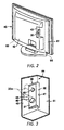
- FIG. 2 is a rear perspective view of the liquid crystal television receiver illustrated in FIG. 1 ;
- FIG. 3 is a partial enlargement of a jack holder of the liquid crystal television receiver illustrated in FIG. 1 ;
- FIG. 4 is a perspective view of the jack holder
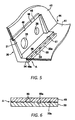
- FIG. 5 is a partial enlargement illustrating an overlapping location between the jack holder and a cabinet
- FIG. 6 is a cross sectional view illustrating an overlapping location between the jack holder and the cabinet.
- FIG. 1 is a side elevational view in section of a liquid crystal television receiver 1.
- the liquid crystal television receiver 1 includes a liquid crystal module 10, a plurality of backlights 11, a control board 20, a jack holder 30, a cabinet 40 and a pair of left and right speakers 60.
- the backlights 11 are disposed on a rear side of the liquid crystal module 10.
- the control board 20 is attached in an erect orientation so that the control board 20 faces the rear side of the liquid crystal module 10.
- the control board 20 includes a plurality of jacks 20a (e.g., socket connectors) for connecting to an antenna lead or to an external device such as headphones.
- jacks 20a e.g., socket connectors
- the jack holder 30 is mounted on the control board 20 to hold the jacks 20a by being screwed in a lateral-facing orientation to an end of the control board 20.
- the cabinet 40 serves as a housing to house the liquid crystal module 10, the backlights 11, the control board 20, the jack holder 30 and the left and right speakers 60.
- the cabinet 40 is molded from a synthetic resin.
- the cabinet 40 has a rear panel 41, a bulge 42 and a side panel 43.
- the rear panel 41, the bulge 42 and the side panel 43 is integrally molded from a synthetic resin as a unitary, one-piece member.
- the bulge 42 is formed in part of the rear panel 41.
- the side panel 43 is formed in part of the bulge 42 to extend rearward from the rear side of the rear panel 41.
- the bulge 42 sticks out to the rear side of the rear panel 41.
- the rear panel 41 and the side panel 43 sticking out from the rear panel 41 form an inside corner 44.
- the cabinet 40 is reinforced in its shape by the inside corner 44.
- the inside corner 44 has a window 45 with an opening 48.
- the opening 48 includes a laterally-facing open portion 46 and a rear-facing open portion 47. Specifically, the opening 48 extends between the rear panel 41 and the side panel 43 across the inside corner 44 to define the laterally-facing open portion 46 and the rear-facing open portion 47.
- the laterally-facing open portion 46 is formed in the side panel 43.
- the rear-facing open portion 47 is linked to the laterally-facing open portion 46, and formed in the rear panel 41.
- the opening 48 formed by the laterally-facing open portion 46 and the rear-facing open portion 47 serves as the window 45.
- the jack holder 30 includes a holder main body 31 and a flange 32.
- the jack holder 30 is a one-piece, unitary member that is injection molded from a suitable resin material.
- the holder main body 31 is formed in a rectangular plate and has a plurality of holes 35 and 36 that align with the jacks 20a (e.g., plug holes) for an antenna jack or headphone jack, respectively.
- the flange 32 protrudes from an edge of the holder main body 31 so that the holder main body 31 and the flange 32 intersect.
- the jack holder 30 is disposed in the window 45.
- the holder main body 31 of the jack holder 30 is disposed in the laterally-facing open portion 46 to cover the laterally-facing open portion 46, and the flange 32 is disposed in the rear-facing open portion 47 to cover the rear-facing open portion 47.
- the flange 32 includes a support edge (e.g., support edge portion) 33 and a relief channel 34.
- the support edge 33 is formed at the end of the flange 32.
- the relief channel 34 is provided at a base of the support edge 33.
- a lateral edge (e.g., edge portion) 49 of the rear-facing open portion 47 overlaps with the support edge 33 in a slender region to form a slender overlapping location (e.g., overlapping portion) A between the support edge 33 and the lateral edge 49 of the rear-facing open portion 47.
- the support edge 33 supports and backs up the lateral edge 49 of the rear-facing open portion 47 rearward from an inside of the liquid crystal television receiver 1. Therefore, the lateral edge 49 of the rear-facing open portion 47 is reinforced by the support edge 33. As a result, cracking and other such damage are prevented.
- the support edge 33 includes a plurality of protrusions 50 formed on a support face 33a that is formed by a rear surface of the support edge 33.
- the protrusions 50 constitutes spacers that are integrally molded from resin on the support edge 33.
- the protrusions 50 are formed on the support face 33a of the support edge 33 of the jack holder 30 at locations spaced apart in a lengthwise direction of the support face 33a so that the protrusions 50 protrude rearward with respect to the support face 33a. Furthermore, as illustrated in FIG.
- the protrusions 50 are interposed between an inner face 49a of the lateral edge 49 and the support face 33a of the support edge 33 to maintain a gap between the inner face 49a of the lateral edge 49 and the support face 33a of the support edge 33.
- the support face 33a and the inner face 49a are both formed as a flat face. Furthermore, the jack holder 30 and the cabinet 40 are designed so that the support face 33a and the inner face 49a overlap entirely at the overlapping location A with a planer contact if the protrusions 50 are not disposed on the support face 33a. Even if the design conditions are set in this way, in actual practice, there will be error in the planarity of the support face 33a or the inner face 49a, and there will also be tilt and other such attachment error. When the overlapping location A is affected by such error, the support face 33a and the inner face 49a overlap in imperfect planar contact if the protrusions 50 are not disposed on the support face 33a.
- the protrusions 50 are integrally molded on the support face 33a of the support edge 33 of the jack holder 30 so that the inner face 49a of the lateral edge 49 and the support face 33a of the support edge 33 are supported away from each other by the protrusions 50. Therefore, it is less likely that there will be vibration of the support edge 33 of the jack holder 30, or of the lateral edge 49 of the cabinet 40, due to sound pressure from the speakers 60. Accordingly, chatter at the overlapping location A is either eliminated or suppressed, without the use of a nonwoven cloth or other such cushioning material.
- the protrusions 50 are provided to the support face 33a of the support edge 33 of the jack holder 30.
- protrusions can instead be provided to the inner face 49a of the lateral edge 49 of the cabinet 40 so that the protrusions protrude towards the support face 33a, and the protrusions 50 can be omitted from the support face 33a.
- the protrusions 50 are preferably molded integrally from a resin on either the inner face 49a of the lateral edge 49 or on the support face 33a of the support edge 33.
- the relief channel 34 is formed at the base of the support edge 33 of the jack holder 30. This prevents the lateral edge 49 overlapping the support edge 33 from lifting up from the support edge 33. Therefore, the protrusions 50 reliably come into resilient contact with the inner face 49a of the lateral edge 49. As a result, the chatter caused by speaker sound pressure can be suppressed even more effectively.
Landscapes
- Engineering & Computer Science (AREA)
- Multimedia (AREA)
- Signal Processing (AREA)
- Devices For Indicating Variable Information By Combining Individual Elements (AREA)
- Casings For Electric Apparatus (AREA)
- Details Of Audible-Bandwidth Transducers (AREA)
Abstract
Description
- This application claims priority to Japanese Patent Application No.
2007-134999 filed on May 22, 2007 2007-134999 - The present invention generally relates to a television receiver. More specifically, the present invention relates to a television receiver having a jack holder attached to a cabinet.
- A conventional liquid crystal television receiver includes a liquid crystal module, a control board, a jack holder, a speaker and a cabinet. The cabinet forms a housing to house the liquid crystal module, the control board, the jack holder and the speaker (see Japanese Laid-Open Patent Application
2006-331827 - When the cabinet is molded from plastic, cabinet walls of the cabinet are made as thin as possible to reduce weight and make a flatter package. Furthermore, with the liquid crystal television receiver having the thin-walled cabinet, an edge of the window in which the jack holder is disposed is supported from an inside with a support edge of the jack holder to prevent cracking of the edge of the window.
- Specifically, the edge of the window of the cabinet is backed up from the inside by the support edge by overlapping the edge of the window with a support face of the support edge of the jack holder. However, when the support edge of the jack holder and the edge of the window are merely overlapped, sound pressure generated by the speaker built into the cabinet tends to generate "chatter" at a place where the support edge of the jack holder and the edge of the window overlap. In particular, the chatter will be much more likely to grate on the ears if the cabinet has thin walls, and an overlapping portion of the support edge of the jack holder and the edge of the window is formed in a slender shape and the two members come into planar contact. This is because even though the design is such that all of the overlapping portion is in planar contact, in actual practice, the overlapping portion is not in perfectly planar contact due to the effect of error in the planarity of the support face or the edge, or tilt and other such attachment error.
- In light of this situation, a nonwoven cloth or other such cushioning material is sandwiched at the overlapping portion between the support face of the support edge of the jack holder and the edge of the window of the cabinet to suppress the generation of chatter by preventing direct contact between the edge and the support face of the support edge.
- Meanwhile, another conventional liquid crystal television receiver interpose a nonwoven cloth or other such elastic sheet between a liquid crystal module and a front cabinet to suppress minute vibrations (chatter) in the front cabinet when audio is outputted (see Japanese Utility Model Registration No.
3,115,175 - Also, with another conventional television receiver, a hollow portion is formed at a contact portion between a display face and a housing during an injection molding of the housing to suppress chatter generated at the contact portion between the display face and the housing (see Japanese Laid-Open Patent Application
2004-297583 - However, the nonwoven cloth or other such cushioning material interposed at the place where chatter occurs to suppress the generation of the chatter increases cost and labor in the assembly process.
- In view of the above, it will be apparent to those skilled in the art from this disclosure that there exists a need for an improved television receiver. This invention addresses this need in the art as well as other needs, which will become apparent to those skilled in the art from this disclosure.
- The present invention was conceived in light of the above-mentioned problems. One object of the present invention is to provide a television receiver with which generation of chatter is suppressed without increasing manufacturing cost.
- In accordance with one aspect of the present invention, a television receiver includes a liquid crystal module, a control board, a jack holder, a cabinet and a plurality of spacers. The control board has a jack. The jack holder is mounted to the control board to hold the jack. The cabinet houses the liquid crystal module, the control board and the jack holder. The cabinet has an opening to which the jack holder is attached from inner side of the cabinet. The spacers are disposed between the jack holder and the cabinet at locations spaced apart where the jack holder and the cabinet overlap. The spacers maintain a gap between the jack holder and the cabinet.
- With the television device of the present invention, it is possible to provide a television receiver with which generation of chatter is suppressed without increasing manufacturing cost.
- These and other objects, features, aspects and advantages of the present invention will become apparent to those skilled in the art from the following detailed descriptions, which, taken in conjunction with the annexed drawings, discloses a preferred embodiment of the present invention.
- Referring now to the attached drawings which form a part of this original disclosure:
-
FIG. 1 is a side elevational view in section of a liquid crystal television receiver in accordance with one embodiment of the present invention; -
FIG. 2 is a rear perspective view of the liquid crystal television receiver illustrated inFIG. 1 ; -
FIG. 3 is a partial enlargement of a jack holder of the liquid crystal television receiver illustrated inFIG. 1 ; -
FIG. 4 is a perspective view of the jack holder; -
FIG. 5 is a partial enlargement illustrating an overlapping location between the jack holder and a cabinet; and -
FIG. 6 is a cross sectional view illustrating an overlapping location between the jack holder and the cabinet. - A preferred embodiment of the present invention will now be explained with reference to the drawings. It will be apparent to those skilled in the art from this disclosure that the following description of the preferred embodiment of the present invention is provided for illustration only and not for the purpose of limiting the invention as defined by the appended claims and their equivalents.
-
FIG. 1 is a side elevational view in section of a liquid crystal television receiver 1. The liquid crystal television receiver 1 includes aliquid crystal module 10, a plurality of backlights 11, acontrol board 20, ajack holder 30, acabinet 40 and a pair of left andright speakers 60. The backlights 11 are disposed on a rear side of theliquid crystal module 10. Thecontrol board 20 is attached in an erect orientation so that thecontrol board 20 faces the rear side of theliquid crystal module 10. Thecontrol board 20 includes a plurality ofjacks 20a (e.g., socket connectors) for connecting to an antenna lead or to an external device such as headphones. Thejack holder 30 is mounted on thecontrol board 20 to hold thejacks 20a by being screwed in a lateral-facing orientation to an end of thecontrol board 20. Thecabinet 40 serves as a housing to house theliquid crystal module 10, the backlights 11, thecontrol board 20, thejack holder 30 and the left andright speakers 60. Thecabinet 40 is molded from a synthetic resin. - As shown in
FIGS. 2 and 3 , thecabinet 40 has arear panel 41, abulge 42 and aside panel 43. Therear panel 41, thebulge 42 and theside panel 43 is integrally molded from a synthetic resin as a unitary, one-piece member. Thebulge 42 is formed in part of therear panel 41. Theside panel 43 is formed in part of thebulge 42 to extend rearward from the rear side of therear panel 41. Thebulge 42 sticks out to the rear side of therear panel 41. Therear panel 41 and theside panel 43 sticking out from therear panel 41 form an insidecorner 44. Thecabinet 40 is reinforced in its shape by theinside corner 44. Theinside corner 44 has awindow 45 with an opening 48. The opening 48 includes a laterally-facing open portion 46 and a rear-facingopen portion 47. Specifically, theopening 48 extends between therear panel 41 and theside panel 43 across theinside corner 44 to define the laterally-facing open portion 46 and the rear-facingopen portion 47. The laterally-facing open portion 46 is formed in theside panel 43. The rear-facingopen portion 47 is linked to the laterally-facing open portion 46, and formed in therear panel 41. Theopening 48 formed by the laterally-facing open portion 46 and the rear-facingopen portion 47 serves as thewindow 45. - As shown in
FIG. 4 , thejack holder 30 includes a holdermain body 31 and aflange 32. Preferably, thejack holder 30 is a one-piece, unitary member that is injection molded from a suitable resin material. The holdermain body 31 is formed in a rectangular plate and has a plurality ofholes jacks 20a (e.g., plug holes) for an antenna jack or headphone jack, respectively. Theflange 32 protrudes from an edge of the holdermain body 31 so that the holdermain body 31 and theflange 32 intersect. As shown inFIG. 3 , thejack holder 30 is disposed in thewindow 45. More specifically, the holdermain body 31 of thejack holder 30 is disposed in the laterally-facing open portion 46 to cover the laterally-facing open portion 46, and theflange 32 is disposed in the rear-facingopen portion 47 to cover the rear-facingopen portion 47. - As shown in
FIGS. 4 and5 , theflange 32 includes a support edge (e.g., support edge portion) 33 and arelief channel 34. Thesupport edge 33 is formed at the end of theflange 32. Therelief channel 34 is provided at a base of thesupport edge 33. A lateral edge (e.g., edge portion) 49 of the rear-facingopen portion 47 overlaps with thesupport edge 33 in a slender region to form a slender overlapping location (e.g., overlapping portion) A between thesupport edge 33 and thelateral edge 49 of the rear-facingopen portion 47. Thesupport edge 33 supports and backs up thelateral edge 49 of the rear-facingopen portion 47 rearward from an inside of the liquid crystal television receiver 1. Therefore, thelateral edge 49 of the rear-facingopen portion 47 is reinforced by thesupport edge 33. As a result, cracking and other such damage are prevented. - The
support edge 33 includes a plurality ofprotrusions 50 formed on asupport face 33a that is formed by a rear surface of thesupport edge 33. Theprotrusions 50 constitutes spacers that are integrally molded from resin on thesupport edge 33. Theprotrusions 50 are formed on thesupport face 33a of thesupport edge 33 of thejack holder 30 at locations spaced apart in a lengthwise direction of thesupport face 33a so that theprotrusions 50 protrude rearward with respect to thesupport face 33a. Furthermore, as illustrated inFIG. 6 , at the slender overlapping location A, theprotrusions 50 are interposed between aninner face 49a of thelateral edge 49 and thesupport face 33a of thesupport edge 33 to maintain a gap between theinner face 49a of thelateral edge 49 and thesupport face 33a of thesupport edge 33. - The
support face 33a and theinner face 49a are both formed as a flat face. Furthermore, thejack holder 30 and thecabinet 40 are designed so that thesupport face 33a and theinner face 49a overlap entirely at the overlapping location A with a planer contact if theprotrusions 50 are not disposed on thesupport face 33a. Even if the design conditions are set in this way, in actual practice, there will be error in the planarity of thesupport face 33a or theinner face 49a, and there will also be tilt and other such attachment error. When the overlapping location A is affected by such error, thesupport face 33a and theinner face 49a overlap in imperfect planar contact if theprotrusions 50 are not disposed on thesupport face 33a. - On the other hand, with the liquid crystal television receiver 1, the
protrusions 50 are integrally molded on thesupport face 33a of thesupport edge 33 of thejack holder 30 so that theinner face 49a of thelateral edge 49 and thesupport face 33a of thesupport edge 33 are supported away from each other by theprotrusions 50. Therefore, it is less likely that there will be vibration of thesupport edge 33 of thejack holder 30, or of thelateral edge 49 of thecabinet 40, due to sound pressure from thespeakers 60. Accordingly, chatter at the overlapping location A is either eliminated or suppressed, without the use of a nonwoven cloth or other such cushioning material. - In this embodiment, the
protrusions 50 are provided to thesupport face 33a of thesupport edge 33 of thejack holder 30. However, protrusions can instead be provided to theinner face 49a of thelateral edge 49 of thecabinet 40 so that the protrusions protrude towards thesupport face 33a, and theprotrusions 50 can be omitted from thesupport face 33a. Also, instead of forming theprotrusions 50 integrally with thejack holder 30 or thecabinet 40, spacers produced as separate components can be interposed between theinner face 49a and thesupport face 33a at locations spaced apart in the lengthwise direction of the overlapping location A so that theinner face 49a of thelateral edge 49 and thesupport face 33a of thesupport edge 33 are supported away from each other by the spacers. However, using the spacers produced as separate components instead of theprotrusions 50 requires extra components. Therefore, theprotrusions 50 are preferably molded integrally from a resin on either theinner face 49a of thelateral edge 49 or on thesupport face 33a of thesupport edge 33. - With the liquid crystal television receiver 1, the
relief channel 34 is formed at the base of thesupport edge 33 of thejack holder 30. This prevents thelateral edge 49 overlapping thesupport edge 33 from lifting up from thesupport edge 33. Therefore, theprotrusions 50 reliably come into resilient contact with theinner face 49a of thelateral edge 49. As a result, the chatter caused by speaker sound pressure can be suppressed even more effectively. - In understanding the scope of the present invention, the term "comprising" and its derivatives, as used herein, are intended to be open ended terms that specify the presence of the stated features, elements, components and groups, but do not exclude the presence of other unstated features, elements, components and groups. The foregoing also applies to words having similar meanings such as the terms, "including", "having" and their derivatives. Also, the terms "part," "section," "portion," "member" or "element" when used in the singular can have the dual meaning of a single part or a plurality of parts. As used herein to describe the present invention, the following directional terms "forward, rearward, above, downward, vertical, horizontal, below and transverse" as well as any other similar directional terms refer to those directions of a liquid crystal module equipped with the present invention. Accordingly, these terms, as utilized to describe the present invention should be interpreted relative to a liquid crystal module equipped with the present invention as used in the normal operating position.
- While a preferred embodiment has been chosen to illustrate the present invention, it will be apparent to those skilled in the art from this disclosure that various changes and modifications can be made herein without departing from the scope of the invention as defined in the appended claims. Furthermore, the foregoing description of the preferred embodiment according to the present invention is provided for illustration only, and not for the purpose of limiting the invention as defined by the appended claims and their equivalents.
Claims (6)
- A television receiver comprising:a liquid crystal module;a control board having a jack;a jack holder mounted to the control board to hold the jack;a cabinet housing the liquid crystal module, the control board and the jack holder, the cabinet having an opening to which the jack holder is attached from inner side of the cabinet; anda plurality of spacers disposed between the jack holder and the cabinet at locations spaced apart where the jack holder and the cabinet overlap, the spacers maintaining a gap between the jack holder and the cabinet.
- The television receiver according to claim 1, wherein
the jack holder has a support edge portion with a support face that overlaps with an inner face of an edge portion of the opening to form an overlapping portion, and
the spacers are disposed at locations spaced apart in a lengthwise direction of the overlapping portion. - The television receiver according to claim 2, wherein
the spacers are integrally formed on one of the support face of the jack holder and the inner face of the cabinet so that the spacers protrude toward the other of the support face of the jack holder and the inner face of the cabinet. - The television receiver according to claim 3, wherein
the spacers are integrally molded from a resin with one of the support face of the jack holder and the inner face of the cabinet as a one-piece, unitary member. - The television receiver according to claim 4, wherein
the jack holder further includes a holder main body having a flat plate shape to which the jack is attached, and a flange protruding from the holder main body,
the cabinet further includes a rear panel and a side panel that protrudes from the rear panel with the rear and side panels forming an inside corner, and
the opening extends between the rear and side panels across the inside corner to define a laterally-facing open portion in the side panel in which the holder main body is disposed, and a rear-facing open portion in the rear panel in which the flange is disposed. - The television receiver according to claim 5, wherein
the jack holder further includes a relief channel formed at a base of the support edge portion that is formed at an end of the flange.
Applications Claiming Priority (1)
| Application Number | Priority Date | Filing Date | Title |
|---|---|---|---|
| JP2007134999A JP4320683B2 (en) | 2007-05-22 | 2007-05-22 | Television receiver |
Publications (2)
| Publication Number | Publication Date |
|---|---|
| EP1995957A2 true EP1995957A2 (en) | 2008-11-26 |
| EP1995957A3 EP1995957A3 (en) | 2011-03-30 |
Family
ID=39535179
Family Applications (1)
| Application Number | Title | Priority Date | Filing Date |
|---|---|---|---|
| EP08009303A Withdrawn EP1995957A3 (en) | 2007-05-22 | 2008-05-20 | Television receiver housing |
Country Status (3)
| Country | Link |
|---|---|
| US (1) | US8154668B2 (en) |
| EP (1) | EP1995957A3 (en) |
| JP (1) | JP4320683B2 (en) |
Cited By (1)
| Publication number | Priority date | Publication date | Assignee | Title |
|---|---|---|---|---|
| EP2034744A1 (en) * | 2007-09-10 | 2009-03-11 | Samsung Electronics Co., Ltd. | Display apparatus and multi display apparatus having the same |
Families Citing this family (3)
| Publication number | Priority date | Publication date | Assignee | Title |
|---|---|---|---|---|
| JP6377488B2 (en) * | 2014-10-09 | 2018-08-22 | 東芝映像ソリューション株式会社 | Electronics |
| KR102224632B1 (en) * | 2014-11-07 | 2021-03-08 | 엘지전자 주식회사 | Display apparatus |
| JP1621288S (en) * | 2018-03-19 | 2019-01-07 |
Citations (4)
| Publication number | Priority date | Publication date | Assignee | Title |
|---|---|---|---|---|
| JPH03115175A (en) | 1989-09-29 | 1991-05-16 | Kawasaki Refract Co Ltd | Refractory concrete material and water-reducing agent for concrete |
| JP2004297583A (en) | 2003-03-27 | 2004-10-21 | Sharp Corp | Case used for electronic equipment |
| JP2006331827A (en) | 2005-05-26 | 2006-12-07 | Funai Electric Co Ltd | Av equipment |
| JP2007134999A (en) | 2005-11-10 | 2007-05-31 | Sharp Corp | Imaging device |
Family Cites Families (13)
| Publication number | Priority date | Publication date | Assignee | Title |
|---|---|---|---|---|
| AU676994B2 (en) * | 1992-04-02 | 1997-04-10 | Adc Telecommunications, Incorporated | Miniature coax jack module |
| JP3074508U (en) | 2000-01-07 | 2001-01-19 | 船井電機株式会社 | Sound equipment cabinets |
| JP2001359022A (en) | 2000-06-12 | 2001-12-26 | Sony Corp | Electronic device |
| US7046310B2 (en) * | 2001-05-21 | 2006-05-16 | Samsung Electronics Co., Ltd. | Display apparatus and a tuner mounted thereon |
| US20050264708A1 (en) * | 2003-10-08 | 2005-12-01 | Chun-Chi Liao | Liquid crystal display device |
| JP4081448B2 (en) * | 2004-01-14 | 2008-04-23 | シャープ株式会社 | Liquid crystal display |
| JP3106184U (en) * | 2004-06-25 | 2004-12-16 | 船井電機株式会社 | Liquid crystal television and liquid crystal display |
| JP3111670U (en) * | 2005-04-18 | 2005-07-28 | 船井電機株式会社 | Panel display television and panel display device |
| JP3115175U (en) | 2005-07-28 | 2005-11-04 | 船井電機株式会社 | Liquid crystal television and display device housing structure |
| JP3117923U (en) * | 2005-10-24 | 2006-01-19 | 船井電機株式会社 | Liquid crystal television device, liquid crystal display device |
| CN100443975C (en) * | 2005-12-21 | 2008-12-17 | 群康科技(深圳)有限公司 | Liquid crystal display device |
| JP4241805B2 (en) * | 2006-11-22 | 2009-03-18 | 船井電機株式会社 | Power switch mounting structure for thin display devices |
| US20090137133A1 (en) * | 2007-11-26 | 2009-05-28 | Pony Gou | F-type right angle jack |
-
2007
- 2007-05-22 JP JP2007134999A patent/JP4320683B2/en not_active Expired - Fee Related
-
2008
- 2008-05-15 US US12/121,010 patent/US8154668B2/en not_active Expired - Fee Related
- 2008-05-20 EP EP08009303A patent/EP1995957A3/en not_active Withdrawn
Patent Citations (4)
| Publication number | Priority date | Publication date | Assignee | Title |
|---|---|---|---|---|
| JPH03115175A (en) | 1989-09-29 | 1991-05-16 | Kawasaki Refract Co Ltd | Refractory concrete material and water-reducing agent for concrete |
| JP2004297583A (en) | 2003-03-27 | 2004-10-21 | Sharp Corp | Case used for electronic equipment |
| JP2006331827A (en) | 2005-05-26 | 2006-12-07 | Funai Electric Co Ltd | Av equipment |
| JP2007134999A (en) | 2005-11-10 | 2007-05-31 | Sharp Corp | Imaging device |
Cited By (1)
| Publication number | Priority date | Publication date | Assignee | Title |
|---|---|---|---|---|
| EP2034744A1 (en) * | 2007-09-10 | 2009-03-11 | Samsung Electronics Co., Ltd. | Display apparatus and multi display apparatus having the same |
Also Published As
| Publication number | Publication date |
|---|---|
| JP2008294500A (en) | 2008-12-04 |
| US20080291344A1 (en) | 2008-11-27 |
| JP4320683B2 (en) | 2009-08-26 |
| EP1995957A3 (en) | 2011-03-30 |
| US8154668B2 (en) | 2012-04-10 |
Similar Documents
| Publication | Publication Date | Title |
|---|---|---|
| US10136203B2 (en) | Display device | |
| EP2262250B1 (en) | Flat panel display device | |
| US20220248115A1 (en) | Display device and speaker unit | |
| RU2628749C2 (en) | Display device | |
| US20160170258A1 (en) | Display Device | |
| US20040155166A1 (en) | Display apparatus | |
| US8154668B2 (en) | Television receiver | |
| US8100706B2 (en) | Back plug-in connector device | |
| KR101077327B1 (en) | E-book | |
| JP2009053399A (en) | Image display device | |
| US20140093330A1 (en) | Attachment structure and display apparatus | |
| CN112104935B (en) | Speaker box | |
| JP2007181015A (en) | Speaker bracket and speaker device | |
| WO2018054172A1 (en) | Display | |
| EP2581783B1 (en) | Display | |
| JP2014063195A (en) | Thin display device | |
| CN103235438B (en) | Display module | |
| JP3115175U (en) | Liquid crystal television and display device housing structure | |
| CN109040918B (en) | Sound cavity structure and electronic equipment | |
| CN222736305U (en) | Microphone installation structure and display device | |
| KR101659749B1 (en) | Display Apparatus for Vehicle | |
| JP2015088820A (en) | Display device and method of attaching speaker of display device | |
| JP4143594B2 (en) | Display integrated speaker and information processing apparatus using the same | |
| CN213545773U (en) | Display module and display device | |
| JP2014225773A (en) | Thin display device |
Legal Events
| Date | Code | Title | Description |
|---|---|---|---|
| PUAI | Public reference made under article 153(3) epc to a published international application that has entered the european phase |
Free format text: ORIGINAL CODE: 0009012 |
|
| AK | Designated contracting states |
Kind code of ref document: A2 Designated state(s): AT BE BG CH CY CZ DE DK EE ES FI FR GB GR HR HU IE IS IT LI LT LU LV MC MT NL NO PL PT RO SE SI SK TR |
|
| AX | Request for extension of the european patent |
Extension state: AL BA MK RS |
|
| PUAL | Search report despatched |
Free format text: ORIGINAL CODE: 0009013 |
|
| RIC1 | Information provided on ipc code assigned before grant |
Ipc: G06F 1/16 20060101ALI20110217BHEP Ipc: H04N 5/64 20060101AFI20080702BHEP |
|
| AK | Designated contracting states |
Kind code of ref document: A3 Designated state(s): AT BE BG CH CY CZ DE DK EE ES FI FR GB GR HR HU IE IS IT LI LT LU LV MC MT NL NO PL PT RO SE SI SK TR |
|
| AX | Request for extension of the european patent |
Extension state: AL BA MK RS |
|
| 17P | Request for examination filed |
Effective date: 20110930 |
|
| AKX | Designation fees paid |
Designated state(s): AT BE BG CH CY CZ DE DK EE ES FI FR GB GR HR HU IE IS IT LI LT LU LV MC MT NL NO PL PT RO SE SI SK TR |
|
| STAA | Information on the status of an ep patent application or granted ep patent |
Free format text: STATUS: THE APPLICATION HAS BEEN WITHDRAWN |
|
| 18W | Application withdrawn |
Effective date: 20150805 |