EP1995906A1 - Non-linear data converter, encoder and decoder - Google Patents
Non-linear data converter, encoder and decoder Download PDFInfo
- Publication number
- EP1995906A1 EP1995906A1 EP08009368A EP08009368A EP1995906A1 EP 1995906 A1 EP1995906 A1 EP 1995906A1 EP 08009368 A EP08009368 A EP 08009368A EP 08009368 A EP08009368 A EP 08009368A EP 1995906 A1 EP1995906 A1 EP 1995906A1
- Authority
- EP
- European Patent Office
- Prior art keywords
- bit string
- mask
- output
- random number
- performs
- Prior art date
- Legal status (The legal status is an assumption and is not a legal conclusion. Google has not performed a legal analysis and makes no representation as to the accuracy of the status listed.)
- Withdrawn
Links
- 238000000034 method Methods 0.000 claims abstract description 185
- 238000006243 chemical reaction Methods 0.000 claims abstract description 43
- 238000004364 calculation method Methods 0.000 claims description 81
- 238000010586 diagram Methods 0.000 description 22
- 238000013478 data encryption standard Methods 0.000 description 12
- 238000007792 addition Methods 0.000 description 2
- 239000011159 matrix material Substances 0.000 description 2
Images



Classifications
-
- H—ELECTRICITY
- H04—ELECTRIC COMMUNICATION TECHNIQUE
- H04L—TRANSMISSION OF DIGITAL INFORMATION, e.g. TELEGRAPHIC COMMUNICATION
- H04L9/00—Cryptographic mechanisms or cryptographic arrangements for secret or secure communications; Network security protocols
- H04L9/06—Cryptographic mechanisms or cryptographic arrangements for secret or secure communications; Network security protocols the encryption apparatus using shift registers or memories for block-wise or stream coding, e.g. DES systems or RC4; Hash functions; Pseudorandom sequence generators
- H04L9/0618—Block ciphers, i.e. encrypting groups of characters of a plain text message using fixed encryption transformation
-
- H—ELECTRICITY
- H04—ELECTRIC COMMUNICATION TECHNIQUE
- H04L—TRANSMISSION OF DIGITAL INFORMATION, e.g. TELEGRAPHIC COMMUNICATION
- H04L9/00—Cryptographic mechanisms or cryptographic arrangements for secret or secure communications; Network security protocols
- H04L9/002—Countermeasures against attacks on cryptographic mechanisms
- H04L9/003—Countermeasures against attacks on cryptographic mechanisms for power analysis, e.g. differential power analysis [DPA] or simple power analysis [SPA]
-
- H—ELECTRICITY
- H04—ELECTRIC COMMUNICATION TECHNIQUE
- H04L—TRANSMISSION OF DIGITAL INFORMATION, e.g. TELEGRAPHIC COMMUNICATION
- H04L2209/00—Additional information or applications relating to cryptographic mechanisms or cryptographic arrangements for secret or secure communication H04L9/00
- H04L2209/04—Masking or blinding
- H04L2209/046—Masking or blinding of operations, operands or results of the operations
-
- H—ELECTRICITY
- H04—ELECTRIC COMMUNICATION TECHNIQUE
- H04L—TRANSMISSION OF DIGITAL INFORMATION, e.g. TELEGRAPHIC COMMUNICATION
- H04L2209/00—Additional information or applications relating to cryptographic mechanisms or cryptographic arrangements for secret or secure communication H04L9/00
- H04L2209/08—Randomization, e.g. dummy operations or using noise
-
- H—ELECTRICITY
- H04—ELECTRIC COMMUNICATION TECHNIQUE
- H04L—TRANSMISSION OF DIGITAL INFORMATION, e.g. TELEGRAPHIC COMMUNICATION
- H04L2209/00—Additional information or applications relating to cryptographic mechanisms or cryptographic arrangements for secret or secure communication H04L9/00
- H04L2209/24—Key scheduling, i.e. generating round keys or sub-keys for block encryption
Definitions
- An aspect of the present invention relates to a non-linear data converter, an encoder and a decoder.
- An encoder or a decoder by a common key encoding system such as a DES (Data Encryption Standard) is mounted on an IC card or the like and widely used. It is very important to protect a secret key from an illegal access.
- DES Data Encryption Standard
- JP-A-2000-66585 showing a countermeasure to an illegal access such as a DPA (Differential Power Analysis) for estimating a secret key from a consumed electric power during the operation of an encoder or a decoder, a method is reported that a predetermined mask value and a mask value obtained by inverting bits thereof are selected at random for each encoding operation or decoding operation to perform a mask process.
- DPA Different Power Analysis
- JP-A-2000-66585 a resistance to a high-order DPA for estimating the secret key from a consumed electric power at a plurality of timings is not considered.
- the present invention is devised to solve the above-described problem and it is an object of the present invention to provide a non-linear data converter, an encoder and a decoder that can ensure a resistance to a high-order DPA.
- a non-linear data converter including: a first converter that performs a first process on an input bit string to output a first output bit string, the first process equivalent to performing: a mask process using a first mask, a non-linear conversion predetermined for performing an encoding or a decoding, and a mask process using a second mask; a second converter that performs a second process on the input bit string to output a second output bit string, the second process equivalent to performing: the mask process using the first mask, the non-linear conversion, and a mask process using an inverted second mask; a third converter that performs a third process on the input bit string to output a third output bit string, the third process equivalent to performing: a mask process using an inverted first mask, the non-linear conversion, and the mask process using the second mask; a fourth converter that performs a fourth process on the input bit string to output a fourth output bit string, the fourth process equivalent to performing: the mask process using the inverted first mask
- a non-linear data converter including: a first converter that performs a first process on an input bit string to output a first output bit string, the first process equivalent to performing: a mask process using a first mask, a non-linear conversion predetermined for performing an encoding or a decoding, and amaskprocess using a secondmask; a first inverter that inverts the first output bit string to output a second output bit string; a second converter that performs a second process on the input bit string to output a third output bit string, the second process equivalent to performing: a mask process using an inverted firstmask, the non-linear conversion, and the mask process using the second mask; a second inverter that inverts the third output bit string to output a fourth output bit string; a generator that generates a random number bit string; and a selector that selects any one of the first to fourth output bit strings based on the random number bit string.
- an encoder including: a key scheduler that generates a j-th enlarged key from a secret key, j being an integer larger than 1 and smaller than z, z being an integer larger than 2; a random number generator that generates a j-th random number bit string; a mask generator that generates a j-th first mask and a j-th second mask based on the j-th random number bit string, apredeterminedfirstmaskandapredetermined second mask; a pre-processor that outputs a first bit string based on an input plaintext block; a j-th function calculator that performs an encoding calculation to a j-th bit string to output a (j+1)-th bit string; and a post-processor that outputs a ciphertext block based on a (Z+1) -th bit string; wherein the j-th function calculator includes: a first converter that performs a first process on the j
- a decoder including: a key scheduler that generates a j-th enlarged key from a secret key, j being an integer larger than 1 and smaller than z, z being an integer larger than 2; a random number generator that generates a j-th random number bit string; a mask generator that generates a j-th first mask and a j-th second mask based on the j-th random number bit string, apredeterminedfirstmaskandapredetermined second mask; a pre-processor that outputs a first bit string based on an input ciphertext block; a j-th function calculator that performs a decoding calculation to a j-th bit string to output a (j+1)-th bit string; and a post-processor that outputs a decoded sentence block based on a (Z+1) -th bit string; wherein the j-th function calculator includes: a first converter that performs a first process
- an encoder including: a key scheduler that generates a j-th enlarged key from a secret key, j being an integer larger than 1 and smaller than z, z being an integer larger than 2; a random number generator that generates a j-th random number bit string; a mask generator that generates a j-th first mask and a j-th second mask based on the j-th random numberbit string, a predetermined first mask and a predetermined second mask; a pre-processor that outputs a first bit string based on an input plaintext block; a j-th function calculator that performs an encoding calculation to a j-th bit string to output a (j+1) -th bit string; and a post-processor that outputs a ciphertext block based on a (Z+1) -th bit string; wherein the j-th function calculator includes: a first converter that performs a first process on the j-th random number bit string;
- a decoder including: a key scheduler that generates a j-th enlarged key from a secret key, j being an integer larger than 1 and smaller than z, z being an integer larger than 2; a random number generator that generates a j-th random number bit string; a mask generator that generates a j-th first mask and a j-th second mask based on the j-th random number bit string, apredeterminedfirstmaskandapredetermined second mask; a pre-processor that outputs a first bit string based on an input ciphertext block; a j-th function calculator that performs a decoding calculation to a j-th bit string to output a (j+1)-th bit string; and a post-processor that outputs a decoded sentence block based on a (Z+1) -th bit string; wherein the j-th function calculator includes: a first converter that performs a first process
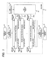
- Fig. 1 is a block diagram showing a basic structure of an encoder 5 of an encoding algorithm DES (Date Encryption Standard).
- DES Date Encryption Standard
- a key schedule part 20 calculates extension keys 21a, 21b,..., 21p by using key information 19 held as secret information.
- the extension keys 21a, 21b,..., 21p are supplied to the round functions 30a to 30p of a first round to a 16 th round.
- the round functions 30a to 30p respectively agitate a plaintext block 9 (64 bits) by using the extension keys 21a, 21b,..., 21p.
- the plaintext block 9 is permutated by an initial permutation IP 10, then respectively agitated by the round functions 30a to 30p and finally permutated by a final permutation FP 40 to become a ciphertext block 41.
- the plaintext block 9 is permutated by the initial permutation IP10, the plaintext block is divided into upper 32 bits and lower 32 bits which are input to a right side input and a left side input of the round function 30a of the first round.
- the round function 30a of the first round outputs two bit strings (32 bits) respectively from a right side output and a left side output.
- the two bit strings output by the round function 30a of the first round are input to the round function 30b of the second round. That is, the bit string output from the right side output of the round function 30a of the first round is input to the right side input of the round function 30b of the second round and the bit string output from the left side output of the round function 30a of the first round is input to the left side input of the round function 30b of the second round.
- the same processes are repeated.
- Two bit strings as outputs of the round function 30p of the 16 th round whose orders are changed are concatenated together and input to the final permutation FP40.
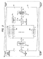
- Fig. 2 is a diagram showing the structure of the round function 30a of the first round. It is understood that the round functions 30b to 30p of the second round to the 16 th round have the same structures.
- the round function 30a of the first round includes an extension permutation E31, an exclusive OR 37 that performs an exclusive OR calculation of an output of the extension permutation E31 and the extension key 21a, eight S boxes (S1, S2, ⁇ , S8) 33a to 33h, a permutation P34, and an exclusive OR 35 for performing an exclusive OR calculation of an output of the permutation P34 and the left side input of 32 bits of the round function 30a of the first round.
- the right side input of 32 bits of the round function 30a of the first round is permutated by the extension permutation E31 and extended to 48 bits.
- the exclusive OR 37 performs an exclusive OR calculation of the output of 48 bits from the extension permutation E31 and the extension key 21a of 48 bits.
- the output of 48 bits from the exclusive OR 37 is equally divided into eight bit strings at intervals of 6 bits which are respectively input to the eight S boxes (S1, S2, together, S8) 33a to 33h.
- the S boxes (S1, S2, ..., S8) 33a to 33h respectively non-linearly convert the input bit strings of 6 bits into bit strings of 4 bits. For instance, a table showing an input and output relation of the S box (S1) 33a of the DES is displayed in table 1.
- Two bits (0 to 3: binary number) composed of a most significant bit and a least significant bit of 6 input bits designate row numbers of the S box (S1)33a shown in table 1.
- the row numbers of the S box (S1) 33a shown in the Table 1 are set to 0, 1, 2 and 3 from an upper part.
- 4 bits (0 to 15: binary number) remaining by excluding the most significant bit and the least significant bit from the six input bits designate column numbers of the S box (S1) 33a shown in the Table 1.
- the column numbers of the S box (S1) 33a shown in the Table 1 are counted as 0, 1, 2, 3,..., 15 from a left end.
- the S box (S1) 33a includes six input lines (one corresponds to 1 bit) and four output lines (one corresponds to 1 bit) and is formed with a suitable combination of wiring and logical elements (NAND, NOR or the like) for connecting the input lines to the output lines so that the input and output relation shown in the table 1 is obtained.
- 32 bits obtained by sequentially concatenating the bit strings (4 bit x 8) respectively output from the S boxes (S1, S2,..., S8) including the output bit string of the S box (S1) 33a to the output bit string of the S box (S8) 33h are permutated by the permutation P34.
- the exclusive OR 35 performs an exclusive OR calculation of the output of 32 bits from the permutation P34 and the left side input of 32 bits of the round function 30a of the first round.
- the calculated result of the exclusive OR 35 becomes the right side output of 32 bits from the round function 30a of the first round.
- the left side output of the round function 30a of the first round is the same as the right side input.
- Fig. 3 is a block diagram showing an encoder 100 according to a first embodiment.
- the encoder 100 according to the first embodiment includes an initial permutation part (IP) 105 for performing an initial permutation of an externally input plaintext block of 64 bits, exclusive ORs 130A and 130B for performing an exclusive OR calculation of a bit string output by the initial permutation part 105 and mask values rmsk 0 and lmsk 0 , exclusive ORs 130a to 130h for performing an exclusive OR calculation for a mask process or a mask removing process, a selector 110L for selecting a left side input of 32 bits of a round function from any one of an output of the exclusive OR 130A, an output of the exclusive OR 130h and an output of the exclusive OR 130b, a selector 110R for selecting the right side input of 32 bits of the round function from any one of an output of the exclusive OR 130B, an output of the exclusive OR 130h and an output of the exclusive OR 130b, registers 120L and 120R for storing outputs of
- the encoder 100 includes four respectively different modified S boxes 141a to 144a (first group of modified S boxes 140a) that are formed in accordance with a non-linear converting system of the S box (S1) 33a of a DES and a selector 110a for selecting one of outputs of the four modified S boxes 141a to 144a of the first group of modified S boxes.
- FIG. 3 Although eight groups of the four modified S boxes 141a to 144a are provided as similarly to Fig. 2 , the boxes are omitted form Fig. 3 due to a limitation in the sheet size. It is understood that there are the first group of modified S boxes 140a including the four respectively different modified S boxes to the eighth group of modified S boxes which are respectively formed in accordance with the non-linear converting system. It is understood that there are selectors 110a to 110h for respectively selecting the outputs of the first group of modified S boxes 140a to the eighth group of modified S boxes 140h.
- Mask values (rmsk j , lmsk j ) of 32 bits and a mask value (ermsk j ) of 48 bits are mask values generated in accordance with the random number bit strings (lmptn j , rmptn j ) and a mask value "a" (it cannot be externally detected) of 4 bits that is predetermined in the encoder 100.
- "a-" designates a bit string of 4 bits obtained by inverting "a” for each bit
- "a'” designates a bit string of 6 bits shown by "0
- "a'-” designates a bit string shown by "1
- " shows a bit concatenation.
- the mask values of (lmsk j , rmsk j ) of 32 bits are generated by extending each of the bits of the random number bit strings (lmptn j , rmptn j ) of 8 bits to 4 bits. For instance, when the random number bit string (lmptn j ) is "11010100", the mask value (lmsk j ) of 32 bits is "a-
- the mask value (rmsk j ) of 32 bits is "a
- Fig. 4 is a block diagram showing equivalent circuits of the modified S boxes (S1 00 , S1 01 , S1 10 , S1 11 ) 141a to 144a provided in the first group of modified boxes 140a in a right side. It is understood that the equivalent circuits are the same as those provided in the second group of modified S boxes 140b to the eighth group of modified S boxes 140h that are not shown in the drawing.
- the random number generating part 145 generates the random number bit strings (rmptn o , lmptn o ) .
- the initial permutation part 105 divides the externally input plaintext block of 64 bits into the upper 32 bits and the lower 32 bits and output the divided plaintext blocks.
- the exclusive OR 130A performs the exclusive OR calculation of the output upper 32 bits and the mask value (rmsk 0 ) calculated from the random number bit string (rmptn 0 ).
- the exclusive OR 130B performs the exclusive OR calculation of the output lower 32 bits and the mask value (lmsk 0 ) calculated from the random number bit string (lmptn 0 ).
- the random number generating part 145 generates the random number bit strings (rmptn j , lmptn j ).
- the exclusive OR 130a performs the exclusive OR calculation of the bit string of 32 bits stored in the register 120R and the mask value (rmsk j ) calculated from the random number bit string (rmptn j ) .
- the next exclusive OR 130b performs the exclusive OR calculation of an output of the exclusive OR 130a and a mask value (lmsk j-1 ). The calculated result thereof is output to the selectors 110R and 110L and the extension permutation part E150, permutated in the extension permutation part E150 and extended to a bit string of 48 bits.
- the output of the exclusive OR 130b is a left output (a bit string of 32 bits) of the round function of a j th round).
- the exclusive OR 130c performs the exclusive OR calculation of "E (rmsk j ) " obtained by performing an extension permutation (E) to the mask value (rmsk j ) and the mask value (ermsk j ).
- the exclusive OR 130d performs the exclusive OR calculation of the bit string of 48 bits output by the extension permutation part (E) 150 and the output of the exclusive OR 103c.
- the exclusive OR 130z performs the exclusive OR calculation of the calculated result of the exclusive OR 130d and an extension key (a round key: rkey j ) input to the round function of the j th round.
- the bit string of 48 bits obtained in such a way is divided into 8 bit strings (a first bit string to an eighth bit string) respectively composed of 6 bits
- the first bit string is input to the first group of modified S boxes 140a (modified S boxes 141a to 144a) to perform the non-linear conversion explained in Fig. 4 .
- the second bit string to the eighth bit string are also input to the second group of modified S boxes 140b to the eighth group of modified S boxes 140h that are not shown in the drawing to perform the non-linear conversion explained in Fig.4 .
- Selectors 110a to 110h determine, for each of the round functions, from which of the modified S boxes (Si 00 , Si 01 , Si 10 , Si 11 ), an output is selected on the basis of an i th bit of the random number bit strings "lmptn j " and "rmptn j " respectively for the first group of modified S boxes 140a to the eighth group of modified S boxes 140h.
- selectors 110b to 110h of the second group of modified S boxes 140b to the eighth group of modified S boxes 140h respectively select the modified S boxes of S2 11 , S3 00 , S4 11 , S5 01 , S6 10 , S7 01 , and S8 00 .
- bit strings of 4 bits of the first group of modified S boxes 140a to the eighth group of modified S boxes 140h selected by the selectors 110b to 110h are sequentially concatenated together to be a bit string of 32 bits which is input to the exclusive OR 130e.
- the exclusive OR 130e performs the exclusive OR calculation of the concatenated bit string of 32 bits and "P -1 (lmptn j )" obtained by performing an inverse calculation of a permutation (P) to the mask value (lmsk j ) calculated from the random number bit string (lmptn j ). Then, the exclusive OR 130f performs the exclusive OR calculation of an output of the exclusive OR 130e and the mask value (lmsk j ). The calculated result is input to the permutation part (P) 160 and permutated.
- the exclusive OR 130g performs the exclusive OR calculation of the bit string of 32 bits output from the permutation part (P) 160 and the bit string of 32 bits stored in the register 120L.
- the exclusive OR 130h performs the exclusive OR calculation of an output of the exclusive OR 130g and a mask value (rmsk j-1 ).
- the bit string of 32 bits of the exclusive OR 130h obtained by performing the above-described calculation is input to the selectors 110R and 110L.
- the selector 110R selects the output (a right side output) of the exclusive OR 130h and outputs to the register 120R.
- the selector 110L selects the output (a left side output) of the exclusive OR 130b and outputs to the register 120L. Since the random number bit strings (rmptn j , lmptn j ) are used for the round function of a j + 1 th round, the random number bit strings are stored.
- the operation of the round function of a 16 th round is the same as those of the round functions of the first to the 15 th rounds that are performed in the second to the 16 th clock cycles except the operations of the selectors 110L and 110R.
- the selector 110R selects the output (the left side output) of the exclusive OR 130b and transmits the output to the register 120R.
- the selector 110 selects the output (the right side output) of the exclusive OR 130h and transmits the output to the register 120L. Since the random number bit strings (rmptn 16 , lmptn 16 ) are used for the exclusive OR calculation (a mask process) performed immediately before the final permutation FP165, the random number bit strings are stored.
- the exclusive OR 130C performs the exclusive OR calculation of the bit string as the right side output of the round function of the 16 th round stored in the register 120L and a mask value (lmsk 16 ) and transmits the calculated result to the final permutation (FP) 165.
- the exclusive OR calculation is applied to the bit string stored in the register 120R with the mask values (rmsk 16 , lmsk 15 ) in the exclusive ORs 130a and 130b.
- the exclusive OR 130D performs the exclusive OR calculation of the bit string as the left side output of the round function of the 16 th round that is output from the exclusive OR 130b and the mask value (rmsk 16 ) and transmits the calculated result to the final permutation (FP) 165.
- the final permutation (FP) 165 concatenates the two bit strings received from the exclusive ORs 130C and 130D and permutates them to output a ciphertext block of 64 bits.
- the encoder 100 includes the S box of the DES in which the mask process is applied to the input bit string by "a'” or “a'-” and the mask process is applied to the output bit string by "a" or “a-” to form the four kinds of modified S boxes and one of the outputs of themodifiedSboxes is selected at random.
- a resistance to a higher order DPA can be ensured.
- a decoder canbe constructed.
- the decoder includes the box of the DES in which the mask process is applied to the input bit string by "a"' or “a'-” and the mask process is applied to the output bit string by "a" or "a-” to form the four kinds of modified S boxes and one of the outputs of the modified S boxes is selected at random.
- the random number generating part 145 generates the two random number bit strings of 8 bits (lmptn j , rmptn j ) every time the calculation of the round function of each round (the first round to the 16 th round) is performed.
- Fig. 5 is a block diagram showing an encoder 100 according to the first modified example of the first embodiment.
- the encoder 100 according to the first modified example is different from the first embodiment in a point that exclusive ORs 130a and 130b are not provided.
- the random number bit string (rmptn j ) that is generated by the random number generating part 145 of the first embodiment in the calculation of the round function of the j th round is a random number bit string (mptn j-1 ) generated by a random number generating part 145 according to the first modified embodiment in the calculation of a round function of a j-1 th round.
- the randomnumber bit string (lmptn j ) generated in the calculation of the round function of the j th round by the random number generating part 145 according to the first embodiment is a random number bit string (mptn j ) generated in the calculation of a round function of a j th round by the random number generating part 145 according to the first modified example.
- An operation of the encoder 100 according to the first modified example is different from that of the first embodiment in view of points that the exclusive ORs 130a and 130b are not provided and the above-described random number bit strings are used as random number bit strings employed for the calculation.
- a decoder can be constructed that can reduce the number of times of generations of the random number bit strings during performing an encoding calculation and makes the analysis by the DPA and the higher order DPA difficult by using the four kinds of S boxes.
- Fig. 6 is a block diagram showing an encoder 100 according to the second modified example of the first embodiment.
- the encoder 100 according to the second modified example is different from the first embodiment in view of points that the modified S boxes (Sl 01 , Sl 11 ) 142a and 144a are not provided and an exclusive OR 130x for inverting all bits of the output of the modified S box (S1 00 ) 141a and an exclusive OR 130y for inverting all bits of the output of the modified S box (S1 10 ) 143a are further provided.
- An operation of the encoder 100 according to the second modified example is different from that of the first embodiment in view of points that a non-linear conversion is not performed in the two modified S boxes (S1 01 , S1 11 ), the exclusive OR 130x inverts all the bits of the output of the modified S box (S1 00 ) 141a and the exclusive OR 130y inverts all the bits of the output of the modified S box (S1 11 ) 144a, and a selector 110a selects any one of outputs of the modified S box (S1 00 ) 141a as an input, the exclusive OR 130x "regarded as the modified S box (S1 01 )", the modified S box (S1 10 ) 143a or the exclusive OR 130y "regarded as the modified S box (S1 11 )" by using random number bit strings (lmptn j , rmptn j ).
- a method that the selector 110a selects one from the four outputs by using the random number bit strings (lmptn j
- the two kinds of the modified S boxes for instance, S1 00 , S1 10
- elements for inverting the bits of the outputs thereof are used so that an analysis by a DPA and a higher order DPA can be made to be difficult and the scale of a circuit of the encoder 100 can be reduced.
- the two kinds of the modified S boxes (for instance, S1 00 , S1 10 ) and elements for inverting the bits of the outputs thereof are used so that a decoder can be constructed in which the scale of a circuit can be reduced and an analysis by a DPA and a higher order DPA can be made to be difficult.
- Fi.7 is a block diagram showing a basic structure of an encoder 205 of an encoding algorithm AES (Advanced Encryption Standard).
- AES Advanced Encryption Standard
- a key schedule part 250 calculates extension keys 251 and 241a to 251j of, for instance, 128 bits, by using key information 249 held as secret information and supplies the extension keys 251 and 251a to 251j to a key adding part 240 and key adding parts 240a to 240j of respective rounds. For instance, a plaintext block of 128 bits is added to the extension key 251 in the key adding part 240 and agitated in round functions 200a to 200j of first to tenth rounds including the additions to the extension keys 251a to 251 to become a ciphertext block.
- the round functions 200a to 200i of the first to the ninth rounds perform processes to input bit strings in SubBytes 210a to 210i, ShiftRows 220a to 220i, MixColumns 230a to 230i and the key adding parts 240a to 240i.
- Fig. 7 only a structure of the round function 200a of the first round is shown.
- the round function 200j of the tenth round performs processes in a SubByte 210j, a ShiftRow 220j and the key adding part 240j to an input bit string.
- the SubBytes 210a to 210j, the ShiftRows 220a to 220j and the MixColumns 230a to 230i divide the input bit string (128 bits) into 16 blocks at intervals of bit strings of 8 bits to process.
- the 16 blocks are designated hereinafter by s 0,0 , S 1, 0 , S 2, 0 , S 3, 0 , S 0, 1 , S 1, 1 , S 2, 1 , S 3, 1 , S 0, 2 , S 1, 2 , S 2, 2 , S 3, 2 , S 0, 3 , S 1, 3 , S 2, 3 , S 3, 3 .
- the SubBytes 210a to 210j include 16 S boxes for performing a non-linear conversion to the input bit strings of 8 bits to output the bit strings of 8 bits. That is, in the SubBytes 210a to 210j, the 16 blocks "s i, k “ (bit strings of 8 bits) as the input bit strings are respectively converted into "S(s i , k )" as the output bit strings.
- Symbol "o" shows an addition modulo four. Namely, when the 16blocks is represented by a matrix, eachrowis changed.
- the MixColumns 230a to 230i perform a matrix conversion of an equation 2 on GF (2 8 ) by regarding the data of 8 bits of each data block as a number of an octal extension body of GF(2 8 ) of GF(2) having an equation 1 established as a defined polynomial.
- the exclusive OR calculation of the input bit strings of 128 bits and the extension keys of 128 bits are performed.
- Fig. 8 is a block diagram showing an encoder 300 according to a second embodiment.
- the encoder 300 includes an exclusive OR 330a for performing a mask process before a plaintext block is input to a round function of a first round, a selector 310 for selecting the masked plaintext block and an output of the round function, a register 320 for storing the input of the round function, exclusive ORs 330b and 330c for performing exclusive OR calculations for a mask process or a mask removing process, a key adding part 350a for performing an exclusive OR calculation of the output of the exclusive OR 330c and an extension key (rkey k-1 ), a SubByte' 360, a ShiftRow 370, aMixColumn' 380, a key adding part 350b of a round function of a 10 th round, an exclusive OR 330d for outputting a ciphertext block and a random number generating part 345 that generates a random number bit string for each round function.
- an exclusive OR 330a for performing a mask process before a plaintext block is input to a round
- the SubByte' 360 includes four respectively different modified S boxes 341a to 344a (a first group of modified S boxes 340a) that are formed in accordance with a non-linear converting system of the S box (S1: not shown in the drawing) of an AES and a selector 310a for selecting one of outputs of the four modified S boxes 341a to 344a of the first group of modified S boxes 340a.
- 16 groups of modified S boxes 341a to 344a are provided, however, in Fig. 8 , other boxes are omitted owing to the size of a sheet. Accordingly, in Fig. 8 , it is understood that there are the first group of modified S boxes 340a including the four respectively different modified S boxes to the 16 th group of modified S boxes 340p which are respectively formed in accordance with the non-linear converting system. It is understood that there are selectors 310a to 310p for respectively selecting the outputs of the first group of modified S boxes 340a to the 16 th group of modified S boxes 340p.
- the selectors 310 and 310a to 310p, the register 320, the exclusive ORs 330a to 330d, the groups of modified S boxes 340a to 340p, the key adding parts 350a and 350b, the ShiftRow 370 and the MixClumn' 380 operate synchronously with a clock signal.
- Mask values (imsk k , omsk k ) of 128 bits are mask values generated in accordance with the random number bit strings (imptn k , omptn k ) of 16 bits and a mask value "a" of 8 bits that is predetermined in the encoder 300.
- the mask values of (imsk k , omsk k ) of 128 bits are generated by respectively extending the bits of the random number bit strings (imptn k , omptn k ) of 16 bits to 8 bits. For instance, when the randomnumber bit string (imptn k ) is "1101010011010100", the mask value (imsk
- Fig. 9 is a block diagram showing equivalent circuits of the modified S boxes (S1 00 , S1 01 , S1 10 , S1 11 ) 341ato344aprovided in the first group of modified S boxes 340a in a left side. It is understood that the S (S1) boxes of the AES in the equivalent circuits shown in Fig. 9 have the same structures and operations as those of the second group of modified S boxes 340b to the 16 th group of modified S boxes 340p that are not shown in the drawing.
- the modified S boxes (Si 00 , Si 01 , Si 10 , Si 11 ) 341a to 344p include eight input lines (one corresponds to 1 bit) and eight output lines (one corresponds to 1 bit) and are formed with suitable combinations of wiring and logical elements (NAND, NOR or the like) for connecting the input lines to the output lines.
- circuits for realizing the modified S boxes (Si 00 , Si 01 , Si 10 , Si 11 ) 341a to 344p are designed not by connecting exclusive OR calculating circuits to the S box circuits of the AES, but in accordance with a new converting table led from the relation between the input and output.
- the random number generating part 345 generates the random number bit strings (imptn o , omptn o ).
- the exclusive OR 330a performs the exclusive OR calculation of an externally received plaintext block of 128 bits and the mask value (omsk 0 ) calculated from the random number bit string (omptn o ).
- the calculated result is stored in the register 320 through the selector 310. Since the random number bit string (omptn o ) is used in the round function of the first round (a second clock cycle), the random number bit string is stored in a memory that is not shown in the drawing.
- the randomnumber generating part 345 generates the random number bit strings (imptn k , omptn k ).
- the exclusive OR 330b performs the exclusive OR calculation of the bit string of 128 bits stored in the register 320 and the mask value (imsk k ).
- the next exclusive OR 330c performs the exclusive OR calculation of an output of the exclusive OR 330b and a mask value (omsk k-1 ).
- the key adding part 350a that receives the calculated result thereof performs the exclusive OR calculation with the extension key (rkey k-1 ).
- bit strings obtained in such a way are divided into 16 blocks respectively composed of 8 bit and input to the first group of modified S boxes to the 16 th group of modified S boxes (340a to 340p). That is, 121 th to 128 th bits form the 16 th block.
- the first group of modified S boxes 340a (modified S boxes 341a to 344a) performs a non-linear converting process to the input bit string to the first block.
- the second to the 16 th groups of modified S boxes 340b to 340p (modified S boxes 341b to 344p, respectively) perform non-linear converting processes to the input bit strings to the second to the 16 th blocks.
- selectors 310b to 310p of the second group of modified S boxes 340b to the 16 th group of modified S boxes 340p respectively select the outputs of the modified S boxes of S2 11 , S3 00 , S4 11 , S5 01 , S6 10 , S7 01 , S8 00 , S9 10 , S10 11 , S11 00 , S12 11 , S13 01 , S14 10 , S15 01 , and S16 00 ".
- bit strings of 8 bits output from the first group of modified S boxes 340a to the 16 th group of modified S boxes 340p selected by the selectors 310a to 310p are sequentially concatenated together to be a bit string of 128 bits which is input to the ShiftRow 370.
- the ShiftRow 370 performs the above-described converting process to the concatenated bit string of 128 bits.
- the random number bit string (omptn k ) is changed so as to meet a process performed in the ShiftRow 370.
- the MixColumn' 380 performs a process to the output of the ShiftRow 370 so that mask values (a or a-) of s' i, k correspond to mask values of s i, k . Specifically, when the mask values corresponding to (s 0, k , s 1, k , s 2, k , s 3, k ) are (a 0,k , a 1, k , a 2, k , a 3, k ), the MixColumn' 380 performs a process corresponding to an equation 3.
- the MixColumn' 380 uses the changed random number bit string (omptn k ) so as to meet the process performed in the ShiftRow 370. After such a process is performed, the selector 310 selects the output of the MixColumn' 380 and outputs it to the register 320. Since the randomnumber bit string (omptn k ) is used in the round function of a k + 1 th round, the random number bit string (omptn k ) is stored.
- the output of the ShiftRow 370 becomes an input of the key adding part 350b.
- the key adding part 350b performs the exclusive OR calculation of the input bit string of 128 bits from the ShiftRow 370 and an extension key (rkey 10 ).
- the exclusive OR 330d performs the exclusive OR calculation of the calculated result of the key adding part 350b and a random number bit string (omptn 10 ) changed so as to meet the process performed in the ShiftRow 370 to output the ciphertext block of 128 bits.
- the mask process is considered to be applied to the input bit string and the output bit string by "a" or "a-" in the S box of the AES to form the four kinds of modified S boxes and select at random which of the modified S boxes is to be used.
- a resistance to a higher order DPA can be ensured.
- a decoder can be constructed that includes the four kinds of modified S boxes formed by considering the mask process to be applied to the input bit string and the output bit string by "a" or "a-" in the S box of the AES and selects at random which of the modified S boxes is to be used.
- a resistance to a higher order DPA can be also ensured.
- the random number generating part 345 generates the two random number bit strings of 16 bits (imptn k , omptn k ) every time the calculation of the round function of each round (the first round to the 10 th round) is performed.
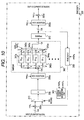
- Fig. 10 is a block diagram showing an encoder 300 according to the first modified example of the second embodiment.
- the encoder 300 according to the first modified example is different from the second embodiment in a point that exclusive ORs 330b and 330c are not provided.
- the random number bit string (imptn k ) that is generated by the random number generating part 345 of the second embodiment in the calculation of the round function of a k th round is a random number bit string (mptn k-1 ) generated by a random number generating part 345 according to the first modified example in the calculation of a round function of a k-1 th round.
- the random number bit string (omptn k ) generated in the calculation of the round function of the k th round by the random number generating part 345 according to the second embodiment is a random number bit string (mptn k ) generated in the calculation of a round function of a k th round by the random number generating part 345 according to the first modified example.
- An operation of the encoder 300 according to the first modified example is different from that of the second embodiment in view of points that the exclusive ORs 330b and 330c are not provided and the above-described random number bit strings are used as random number bit strings employed for the calculation.
- a decoder can be constructed that can reduce the number of times of generations of the random number bit strings during performing an encoding calculation and makes the analysis by the DPA and the higher order DPA difficult by using the four kinds of S boxes.
- two kinds of modified S boxes (Si 00 , Si 10 ) are prepared and two exclusive ORs are prepared for respectively inverting all bits of the outputs of the two modified S boxes (Si 00 , Si 10 ).
- Fig. 11 is a block diagram showing an encoder 300 according to the second modified example of the second embodiment.
- the encoder 300 according to the second modified example is different from the second embodiment in view of points that the modified S boxes (S1 01 , S1 11 ) 342a and 344a are not provided and an exclusive OR 330x for inverting all bits of the output of the modified S box (S1 00 ) 341a and an exclusive OR 330y for inverting all bits of the output of the modified S box (S1 10 ) 343a are further provided.
- An operation of the encoder 300 according to the second modified example of the second embodiment is different from that of the second embodiment in view of points that an operation (a non-linear conversion) is not performed in the modified S boxes (S1 01 , S1 11 ), the exclusive OR 330x inverts all the bits of the output of the modified S box (S1 00 ) 341a and the exclusive OR 330y inverts all the bits of the output of the modified S box (S1 10 ) 343a, and a selector 310a selects any one of outputs of the modified S box (S1 00 ) 341a as an input, the exclusive OR 330x, the modified S box (S1 10 ) 343a or the exclusive OR 330y by using the random number bit strings (imptn k , omptn k ).
- the two kinds of the modified S boxes for instance, S1 00 , S1 10
- elements for inverting the bits of the outputs thereof are used so that an analysis by a DPA and a higher order DPA can be made to be difficult and the scale of a circuit of the encoder 300 can be reduced.
- the two kinds of the modified S boxes (for instance, S1 00 , S1 10 ) and elements for inverting the bits of the outputs thereof are used so that a decoder can be constructed in which the scale of a circuit can be reduced and an analysis by a DPA and a higher order DPA can be made to be difficult.
- the present invention is not directly limited to the above-described embodiments and components may be modified and embodied within a scope without departing from a gist thereof in the course of embodying. Further, a plurality of components disclosed in the above-described embodiments may be suitably combined together so that various inventions can be devised. For instance, some components may be deleted from all the components disclosed in the embodiments. Further, the components included in the different embodiments maybe suitably combined together.
- a resistance to a high-order DPA can be ensured.
Landscapes
- Engineering & Computer Science (AREA)
- Computer Security & Cryptography (AREA)
- Computer Networks & Wireless Communication (AREA)
- Signal Processing (AREA)
- Compression, Expansion, Code Conversion, And Decoders (AREA)
Abstract
Description
- An aspect of the present invention relates to a non-linear data converter, an encoder and a decoder.
- An encoder or a decoder by a common key encoding system such as a DES (Data Encryption Standard) is mounted on an IC card or the like and widely used. It is very important to protect a secret key from an illegal access.
- For instance, as disclosed in
JP-A-2000-66585 - However, in
JP-A-2000-66585 - The present invention is devised to solve the above-described problem and it is an object of the present invention to provide a non-linear data converter, an encoder and a decoder that can ensure a resistance to a high-order DPA.
- According to an aspect of the present invention, there is provided a non-linear data converter including: a first converter that performs a first process on an input bit string to output a first output bit string, the first process equivalent to performing: a mask process using a first mask, a non-linear conversion predetermined for performing an encoding or a decoding, and a mask process using a second mask; a second converter that performs a second process on the input bit string to output a second output bit string, the second process equivalent to performing: the mask process using the first mask, the non-linear conversion, and a mask process using an inverted second mask; a third converter that performs a third process on the input bit string to output a third output bit string, the third process equivalent to performing: a mask process using an inverted first mask, the non-linear conversion, and the mask process using the second mask; a fourth converter that performs a fourth process on the input bit string to output a fourth output bit string, the fourth process equivalent to performing: the mask process using the inverted first mask, the non-linear conversion, and the mask process using the inverted second mask; a generator that generates a random number bit string; and a selector that selects any one of the first to fourth output bit strings based on the random number bit string.
- According to anther aspect of the present invention, there is provided a non-linear data converter including: a first converter that performs a first process on an input bit string to output a first output bit string, the first process equivalent to performing: a mask process using a first mask, a non-linear conversion predetermined for performing an encoding or a decoding, and amaskprocess using a secondmask; a first inverter that inverts the first output bit string to output a second output bit string; a second converter that performs a second process on the input bit string to output a third output bit string, the second process equivalent to performing: a mask process using an inverted firstmask, the non-linear conversion, and the mask process using the second mask; a second inverter that inverts the third output bit string to output a fourth output bit string; a generator that generates a random number bit string; and a selector that selects any one of the first to fourth output bit strings based on the random number bit string.
- According to still anther aspect of the present invention, there is provided an encoder including: a key scheduler that generates a j-th enlarged key from a secret key, j being an integer larger than 1 and smaller than z, z being an integer larger than 2; a random number generator that generates a j-th random number bit string; a mask generator that generates a j-th first mask and a j-th second mask based on the j-th random number bit string, apredeterminedfirstmaskandapredetermined second mask; a pre-processor that outputs a first bit string based on an input plaintext block; a j-th function calculator that performs an encoding calculation to a j-th bit string to output a (j+1)-th bit string; and a post-processor that outputs a ciphertext block based on a (Z+1) -th bit string; wherein the j-th function calculator includes: a first converter that performs a first process on the j-th bit string to output a first converted bit string, the first process equivalent to performing: a mask process using the j-th first mask, a non-linear conversion predetermined for performing an encoding, and a mask process using the j-th second mask; a second converter that performs a second process on the j-th bit string to output a second converted bit string, the second process equivalent to performing: the mask process using the j-th first mask, the non-linear conversion, and a mask process using an inverted j-th secondmask; a third converter that performs a thirdprocess on the j-th bit string to output a third converted bit string, the third process equivalent to performing: a mask process using an inverted j-th first mask, the non-linear conversion, and the mask process using the j-th second mask; a fourth converter that performs a fourth process on the j-th bit string to output a fourth converted bit string, the fourth process equivalent to performing: the mask process using the inverted j-th first mask, the non-linear conversion, and the mask process using the inverted j-th second mask; and a selector that selects any one of the first to fourth converted bit strings based on the j-th random number bit string to output as the (j+1)-th bit string.
- According to still anther aspect of the present invention, there is provided a decoder including: a key scheduler that generates a j-th enlarged key from a secret key, j being an integer larger than 1 and smaller than z, z being an integer larger than 2; a random number generator that generates a j-th random number bit string; a mask generator that generates a j-th first mask and a j-th second mask based on the j-th random number bit string, apredeterminedfirstmaskandapredetermined second mask; a pre-processor that outputs a first bit string based on an input ciphertext block; a j-th function calculator that performs a decoding calculation to a j-th bit string to output a (j+1)-th bit string; and a post-processor that outputs a decoded sentence block based on a (Z+1) -th bit string; wherein the j-th function calculator includes: a first converter that performs a first process on the j-th bit string to output a first converted bit string, the first process equivalent to performing: a mask process using the j-th first mask, a non-linear conversion predetermined for performing an encoding, and a mask process using the j-th second mask; a second converter that performs a second process on the j-th bit string to output a second converted bit string, the second process equivalent to performing: the mask process using the j-th first mask, the non-linear conversion, and a mask process using an inverted j -th secondmask; a third converter that performs a thirdprocess on the j-th bit string to output a third converted bit string, the third process equivalent to performing: a mask process using an inverted j-th first mask, the non-linear conversion, and the mask process using the j-th second mask; a fourth converter that performs a fourth process on the j-th bit string to output a fourth converted bit string, the fourth process equivalent to performing: the mask process using the inverted j-th first mask, the non-linear conversion, and the mask process using the inverted j-th second mask; and a selector that selects any one of the first to fourth converted bit strings based on the j-th random number bit string to output as the (j+1)-th bit string.
- According to still anther aspect of the present invention, there is provided an encoder including: a key scheduler that generates a j-th enlarged key from a secret key, j being an integer larger than 1 and smaller than z, z being an integer larger than 2; a random number generator that generates a j-th random number bit string; a mask generator that generates a j-th first mask and a j-th second mask based on the j-th random numberbit string, a predetermined first mask and a predetermined second mask; a pre-processor that outputs a first bit string based on an input plaintext block; a j-th function calculator that performs an encoding calculation to a j-th bit string to output a (j+1) -th bit string; and a post-processor that outputs a ciphertext block based on a (Z+1) -th bit string; wherein the j-th function calculator includes: a first converter that performs a first process on the j-th bit string to output a first converted bit string, the first process equivalent to performing: a mask process using the j-th first mask, a non-linear conversion predetermined for performing an encoding process, and a mask process using the j-th second mask; a first inverter that inverts the first converted bit string to output a second converted bit string; a second converter that performs a secondprocess on the j-thbit string to output a third converted bit string, the second process equivalent to performing: a mask process using an inverted j-th first mask, the non-linear conversion, and the mask process using the j-th second mask; a second inverter that inverts the third converted bit string to output a fourth converted bit string; and a selector that selects any one of the first to fourth converted bit strings based on the j-th random number bit string to output as the (j+1)-th bit string.
- According to still anther aspect of the present invention, there is provided a decoder including: a key scheduler that generates a j-th enlarged key from a secret key, j being an integer larger than 1 and smaller than z, z being an integer larger than 2; a random number generator that generates a j-th random number bit string; a mask generator that generates a j-th first mask and a j-th second mask based on the j-th random number bit string, apredeterminedfirstmaskandapredetermined second mask; a pre-processor that outputs a first bit string based on an input ciphertext block; a j-th function calculator that performs a decoding calculation to a j-th bit string to output a (j+1)-th bit string; and a post-processor that outputs a decoded sentence block based on a (Z+1) -th bit string; wherein the j-th function calculator includes: a first converter that performs a first process on the j-th bit string to output a first converted bit string, the first process equivalent to performing: a mask process using the j-th first mask, a non-linear conversion predetermined for performing an encoding process, and a mask process using the j-th second mask; a first inverter that inverts the first converted bit string to output a second converted bit string; a second converter that performs a secondprocess on the j-thbit string to output a third converted bit string, the second process equivalent to performing: a mask process using an inverted j-th first mask, the non-linear conversion, and the mask process using the j-th second mask; a second inverter that inverts the third converted bit string to output a fourth converted bit string; and a selector that selects any one of the first to fourth converted bit strings based on the j-th random number bit string to output as the (j+1)-th bit string.
- Embodiment may be described in detail with reference to the accompanying drawings, in which:
-
Fig. 1 is a block diagram showing a basic structure of an encoder based on an encoding algorithm DES; -
Fig. 2 is a block diagram showing a basic structure of a round function of a first round of the encoding algorithm DES; -
Fig. 3 is a block diagram showing a structure of an encoding calculation circuit according to a first embodiment; -
Fig.4 is a block diagram showing equivalent circuits of modified S boxes (S100, S101, S110, S111) according to the first embodiment; -
Fig. 5 is a block diagram showing a structure of an encoding calculation circuit according to a first modified example of the first embodiment; -
Fig. 6 is ablock diagram showing a structure of an encoding calculation circuit according to a second modified example of the first embodiment; -
Fig. 7 is a block diagram showing a basic structure of an encoder based on an encoding algorithm AES; -
Fig. 8 is a block diagram showing a structure of an encoding calculation circuit according to a second embodiment; -
Fig.9 is a block diagram showing equivalent circuits of modified S boxes (S100, S101, S110, S111) according to the second embodiment; -
Fig. 10 is a block diagram showing a structure of an encoding calculation circuit according to a first modified example of the second embodiment; and -
Fig. 11 is a block diagram showing a structure of an encoding calculation circuit according to a second modified example of the second embodiment. - Embodiments will be described below.
-
Fig. 1 is a block diagram showing a basic structure of anencoder 5 of an encoding algorithm DES (Date Encryption Standard). - A
key schedule part 20 calculatesextension keys key information 19 held as secret information. Theextension keys round functions 30a to 30p of a first round to a 16 th round. Theround functions 30a to 30p respectively agitate a plaintext block 9 (64 bits) by using theextension keys initial permutation IP 10, then respectively agitated by theround functions 30a to 30p and finally permutated by afinal permutation FP 40 to become a ciphertext block 41. - After the plaintext block 9 is permutated by the initial permutation IP10, the plaintext block is divided into upper 32 bits and lower 32 bits which are input to a right side input and a left side input of the
round function 30a of the first round. Similarly, theround function 30a of the first round outputs two bit strings (32 bits) respectively from a right side output and a left side output. - The two bit strings output by the
round function 30a of the first round are input to theround function 30b of the second round. That is, the bit string output from the right side output of theround function 30a of the first round is input to the right side input of theround function 30b of the second round and the bit string output from the left side output of theround function 30a of the first round is input to the left side input of theround function 30b of the second round. After that, in theround functions 30b to 30p of the second round to the 16 th round, the same processes are repeated. Two bit strings as outputs of theround function 30p of the 16 th round whose orders are changed are concatenated together and input to the final permutation FP40. -
Fig. 2 is a diagram showing the structure of theround function 30a of the first round. It is understood that theround functions 30b to 30p of the second round to the 16 th round have the same structures. - The
round function 30a of the first round includes an extension permutation E31, an exclusive OR 37 that performs an exclusive OR calculation of an output of the extension permutation E31 and theextension key 21a, eight S boxes (S1, S2,···, S8) 33a to 33h, a permutation P34, and an exclusive OR 35 for performing an exclusive OR calculation of an output of the permutation P34 and the left side input of 32 bits of theround function 30a of the first round. - The right side input of 32 bits of the
round function 30a of the first round is permutated by the extension permutation E31 and extended to 48 bits. Then, the exclusive OR 37 performs an exclusive OR calculation of the output of 48 bits from the extension permutation E31 and theextension key 21a of 48 bits. The output of 48 bits from the exclusive OR 37 is equally divided into eight bit strings at intervals of 6 bits which are respectively input to the eight S boxes (S1, S2,......, S8) 33a to 33h. - The S boxes (S1, S2, ..., S8) 33a to 33h respectively non-linearly convert the input bit strings of 6 bits into bit strings of 4 bits. For instance, a table showing an input and output relation of the S box (S1) 33a of the DES is displayed in table 1.

- Two bits (0 to 3: binary number) composed of a most significant bit and a least significant bit of 6 input bits designate row numbers of the S box (S1)33a shown in table 1. The row numbers of the S box (S1) 33a shown in the Table 1 are set to 0, 1, 2 and 3 from an upper part. 4 bits (0 to 15: binary number) remaining by excluding the most significant bit and the least significant bit from the six input bits designate column numbers of the S box (S1) 33a shown in the Table 1. The column numbers of the S box (S1) 33a shown in the Table 1 are counted as 0, 1, 2, 3,..., 15 from a left end.
- Assuming that the bit string input to the S box (S1) 33a is "011011", the row number is "1" (01/b: binary) and the column number is "13" (1101/b), so that an output value "5" is obtained. Accordingly, the output of the S box (S1) 33a is "0101". The S box (S1) 33a includes six input lines (one corresponds to 1 bit) and four output lines (one corresponds to 1 bit) and is formed with a suitable combination of wiring and logical elements (NAND, NOR or the like) for connecting the input lines to the output lines so that the input and output relation shown in the table 1 is obtained.
- 32 bits obtained by sequentially concatenating the bit strings (4 bit x 8) respectively output from the S boxes (S1, S2,..., S8) including the output bit string of the S box (S1) 33a to the output bit string of the S box (S8) 33h are permutated by the permutation P34. Then, the exclusive OR 35 performs an exclusive OR calculation of the output of 32 bits from the permutation P34 and the left side input of 32 bits of the
round function 30a of the first round. The calculated result of the exclusive OR 35 becomes the right side output of 32 bits from theround function 30a of the first round. The left side output of theround function 30a of the first round is the same as the right side input. -
Fig. 3 is a block diagram showing anencoder 100 according to a first embodiment. Theencoder 100 according to the first embodiment includes an initial permutation part (IP) 105 for performing an initial permutation of an externally input plaintext block of 64 bits,exclusive ORs initial permutation part 105 and mask values rmsk0 and lmsk0,exclusive ORs 130a to 130h for performing an exclusive OR calculation for a mask process or a mask removing process, aselector 110L for selecting a left side input of 32 bits of a round function from any one of an output of the exclusive OR 130A, an output of the exclusive OR 130h and an output of the exclusive OR 130b, aselector 110R for selecting the right side input of 32 bits of the round function from any one of an output of the exclusive OR 130B, an output of the exclusive OR 130h and an output of the exclusive OR 130b, registers 120L and 120R for storing outputs of 32 bits from theselectors number generating part 145 for generating a random number bit string for each round function, an extension permutation part (E) 150, a permutation part (P) 160,exclusive ORs - The
encoder 100 according to the first embodiment includes four respectively different modifiedS boxes 141a to 144a (first group of modifiedS boxes 140a) that are formed in accordance with a non-linear converting system of the S box (S1) 33a of a DES and aselector 110a for selecting one of outputs of the four modifiedS boxes 141a to 144a of the first group of modified S boxes. - Although eight groups of the four modified
S boxes 141a to 144a are provided as similarly toFig. 2 , the boxes are omitted formFig. 3 due to a limitation in the sheet size. It is understood that there are the first group of modifiedS boxes 140a including the four respectively different modified S boxes to the eighth group of modified S boxes which are respectively formed in accordance with the non-linear converting system. It is understood that there areselectors 110a to 110h for respectively selecting the outputs of the first group of modifiedS boxes 140a to the eighth group of modified S boxes 140h. - The
initial permutation 105, theselectors registers exclusive ORs 130A to 130D, 130a to 130h and 130z, the first group of modifiedS boxes 140a to the eighth group of modified S boxes 140h (in this case, a second group of modified S boxes 140b to the eighth group of modified S boxes 140h are not shown), theextension permutation part 150, thepermutation part 160 and thefinal permutation part 165 operate synchronously with a clock signal. - The random
number generating part 145 generates two random number bit strings of 8 bits (lmptnj, rmptnj) (j = 1, 2,..., 16) respectively for the calculation of the round functions (from the first round to the 16 th round). - Mask values (rmskj, lmskj) of 32 bits and a mask value (ermskj) of 48 bits are mask values generated in accordance with the random number bit strings (lmptnj, rmptnj) and a mask value "a" (it cannot be externally detected) of 4 bits that is predetermined in the
encoder 100. In a below-description, "a-" designates a bit string of 4 bits obtained by inverting "a" for each bit, "a'" designates a bit string of 6 bits shown by "0||a||0|" and "a'-" designates a bit string shown by "1||a-||1". "||" shows a bit concatenation. - The mask values of (lmskj, rmskj) of 32 bits are generated by extending each of the bits of the random number bit strings (lmptnj, rmptnj) of 8 bits to 4 bits. For instance, when the random number bit string (lmptnj) is "11010100", the mask value (lmskj) of 32 bits is "a-||a-||a||a-||a||a-||a||a" (a is 4 bits). When the random number bit string (rmptnj) is "01011010", the mask value (rmskj) of 32 bits is "a || a-||a|| a-||a-||a||a-||a".
- Themaskvalue (ermskj) of 48 bits is generated by extending each of the bits of the random number bit string (rmptnj) of 8 bits to 6 bits. When the random number bit string (rmptnj) is "01011010", the mask value of (ermskj) of 48 bits is "0||a||0||1||a-||1||0||a||0||1||a-||1||1||a-||1++0||a||0|| 1||a-||1||0||a||0".
-
Fig. 4 is a block diagram showing equivalent circuits of the modified S boxes (S100, S101, S110, S111) 141a to 144a provided in the first group of modifiedboxes 140a in a right side. It is understood that the equivalent circuits are the same as those provided in the second group of modified S boxes 140b to the eighth group of modified S boxes 140h that are not shown in the drawing. - When a bit string x of 6 bits is input to the S boxes (Si) 33a to 33h (i = 1, 2,..., 8) of the DES, the S boxes output bit strings Si (x) of 4 bits. That is, when the bit string of 6 bits is input to the first modified S boxes (S100, S101, S110, S111) 141a to 144a to the eighth modified S boxes (S800, S801, S810, S811) 141h to 144h, the first to eighth modified S boxes output bit strings of 4 bits Si00 (x) Si01(x), Si10(x) and Si11(x) (i = 1, 2,..., 8).
- An input and output relationof the first to eighthmodified S boxes (Si00, Si01, Si10, Si11) 141a to 144h will be shown below. A sign "+" shows an exclusive OR calculation hereinafter.
- Namely, the first to eighth modified S boxes (Si00, Si01, Si10, Si11) 141a to 144h are designed on the basis of a converting table led from the input and output relation so that the first to eighth modified S boxes generate the bit strings of 4 bits from the bit strings of 6 bits to calculate as "Si00(x) = Si (x +a') +a, Si01(x) = Si(x+a') + a-, Si10 (x) = Si (x+a' -) + a, Si11(x) = Si(x+a'-) + a-" (i = 1, 2,..., 8).
- An operation of the
encoder 100 according to the first embodiment will be described for each clock cycle by referring toFig. 3 . - Initially, the random
number generating part 145 generates the random number bit strings (rmptno, lmptno) . Theinitial permutation part 105 divides the externally input plaintext block of 64 bits into the upper 32 bits and the lower 32 bits and output the divided plaintext blocks. The exclusive OR 130A performs the exclusive OR calculation of the output upper 32 bits and the mask value (rmsk0) calculated from the random number bit string (rmptn0). Theexclusive OR 130B performs the exclusive OR calculation of the output lower 32 bits and the mask value (lmsk0) calculated from the random number bit string (lmptn0). The calculated results are respectively stored in theregisters selectors - The random
number generating part 145 generates the random number bit strings (rmptnj, lmptnj). The exclusive OR 130a performs the exclusive OR calculation of the bit string of 32 bits stored in theregister 120R and the mask value (rmskj) calculated from the random number bit string (rmptnj) . The next exclusive OR 130b performs the exclusive OR calculation of an output of the exclusive OR 130a and a mask value (lmskj-1). The calculated result thereof is output to theselectors - The exclusive OR 130c performs the exclusive OR calculation of "E (rmskj) " obtained by performing an extension permutation (E) to the mask value (rmskj) and the mask value (ermskj). The
exclusive OR 130d performs the exclusive OR calculation of the bit string of 48 bits output by the extension permutation part (E) 150 and the output of the exclusive OR 103c. The exclusive OR 130z performs the exclusive OR calculation of the calculated result of the exclusive OR 130d and an extension key (a round key: rkeyj) input to the round function of the j th round. The bit string of 48 bits obtained in such a way is divided into 8 bit strings (a first bit string to an eighth bit string) respectively composed of 6 bits - Then, the first bit string is input to the first group of modified
S boxes 140a (modifiedS boxes 141a to 144a) to perform the non-linear conversion explained inFig. 4 . The second bit string to the eighth bit string are also input to the second group of modified S boxes 140b to the eighth group of modified S boxes 140h that are not shown in the drawing to perform the non-linear conversion explained inFig.4 . -
Selectors 110a to 110h (selectors 110b to 110h are not shown in the drawing) determine, for each of the round functions, from which of the modified S boxes (Si00, Si01, Si10, Si11), an output is selected on the basis of an i th bit of the random number bit strings "lmptnj" and "rmptnj" respectively for the first group of modifiedS boxes 140a to the eighth group of modified S boxes 140h. - When the random number bit string of the round function of the j th round is "rmptnj= 11010100, Imptnj = 01011010", since first bits of "rmptnj" and "lmptnj " are "1" and "0", the
selector 110a selects an "output of the modified S box (Sl10) 143a" from the first group of modifiedS boxes 140a. Outputs of modified S boxes (Sixy) selected by theselectors 110a to 110h are likewise determined by substituting the i th bit of "rmptnj" for "x" and the i th bit of "lmptnj " for "y". It is understood that the selectors 110b to 110h of the second group of modified S boxes 140b to the eighth group of modified S boxes 140h respectively select the modified S boxes of S211, S300, S411, S501, S610, S701, and S800. - The bit strings of 4 bits of the first group of modified
S boxes 140a to the eighth group of modified S boxes 140h selected by the selectors 110b to 110h are sequentially concatenated together to be a bit string of 32 bits which is input to the exclusive OR 130e. - After that, the exclusive OR 130e performs the exclusive OR calculation of the concatenated bit string of 32 bits and "P-1 (lmptnj)" obtained by performing an inverse calculation of a permutation (P) to the mask value (lmskj) calculated from the random number bit string (lmptnj). Then, the exclusive OR 130f performs the exclusive OR calculation of an output of the exclusive OR 130e and the mask value (lmskj). The calculated result is input to the permutation part (P) 160 and permutated.
- Subsequently, the exclusive OR 130g performs the exclusive OR calculation of the bit string of 32 bits output from the permutation part (P) 160 and the bit string of 32 bits stored in the
register 120L. The exclusive OR 130h performs the exclusive OR calculation of an output of the exclusive OR 130g and a mask value (rmskj-1). - The bit string of 32 bits of the exclusive OR 130h obtained by performing the above-described calculation is input to the
selectors selector 110R selects the output (a right side output) of the exclusive OR 130h and outputs to theregister 120R. Theselector 110L selects the output (a left side output) of the exclusive OR 130b and outputs to theregister 120L. Since the random number bit strings (rmptnj, lmptnj) are used for the round function of a j + 1 th round, the random number bit strings are stored. - The operation of the round function of a 16 th round is the same as those of the round functions of the first to the 15 th rounds that are performed in the second to the 16 th clock cycles except the operations of the
selectors - In the operation of the round function of the 16 th round performed in a 17 th clock cycle, the
selector 110R selects the output (the left side output) of the exclusive OR 130b and transmits the output to theregister 120R. Theselector 110 selects the output (the right side output) of the exclusive OR 130h and transmits the output to theregister 120L. Since the random number bit strings (rmptn16, lmptn16) are used for the exclusive OR calculation (a mask process) performed immediately before the final permutation FP165, the random number bit strings are stored. - The
exclusive OR 130C performs the exclusive OR calculation of the bit string as the right side output of the round function of the 16 th round stored in theregister 120L and a mask value (lmsk16) and transmits the calculated result to the final permutation (FP) 165. The exclusive OR calculation is applied to the bit string stored in theregister 120R with the mask values (rmsk16, lmsk15) in theexclusive ORs exclusive ORs - As described above, it can be considered that the
encoder 100 includes the S box of the DES in which the mask process is applied to the input bit string by "a'" or "a'-" and the mask process is applied to the output bit string by "a" or "a-" to form the four kinds of modified S boxes and one of the outputs of themodifiedSboxes is selected at random. Thus, a resistance to a higher order DPA can be ensured. - As similar to the
encoder 100, a decoder canbe constructed. Similarly, it is considered that the decoder includes the box of the DES in which the mask process is applied to the input bit string by "a"' or "a'-" and the mask process is applied to the output bit string by "a" or "a-" to form the four kinds of modified S boxes and one of the outputs of the modified S boxes is selected at random. Thus, when the ciphertext block is decoded to the plaintext block, a resistance to a higher order DPA can be also ensured. - As described above, in the first embodiment, the random
number generating part 145 generates the two random number bit strings of 8 bits (lmptnj, rmptnj) every time the calculation of the round function of each round (the first round to the 16 th round) is performed. - As compared therewith, in a first modified example of the first embodiment, an explanation will be given to a form where a random
number generating part 145 generates two random number bit strings (mptn0, mptn1) of 8 bits in accordance with the calculation of a round function of, for instance, a first round and generates one random number bit string (mptnj) of 8 bits in the calculation of a round function of a j th round (j = 2,..., 16). -
Fig. 5 is a block diagram showing anencoder 100 according to the first modified example of the first embodiment. - The
encoder 100 according to the first modified example is different from the first embodiment in a point thatexclusive ORs number generating part 145 of the first embodiment in the calculation of the round function of the j th round is a random number bit string (mptnj-1) generated by a randomnumber generating part 145 according to the first modified embodiment in the calculation of a round function of a j-1 th round. The randomnumber bit string (lmptnj) generated in the calculation of the round function of the j th round by the randomnumber generating part 145 according to the first embodiment is a random number bit string (mptnj) generated in the calculation of a round function of a j th round by the randomnumber generating part 145 according to the first modified example. - An operation of the
encoder 100 according to the first modified example is different from that of the first embodiment in view of points that theexclusive ORs - In the
encoder 100 according to the first modified example of the first embodiment, the reason why theexclusive ORs - In the first modified example, when the calculation of the round function of the j th round is performed, a mask process and a mask removing process are performed by using the random number bit strings (mptnj, mptnj-1) generated during the calculations of the round functions of the j th round and the j-1 th round. Therefore, both mask values used when the
exclusive ORs exclusive ORs - As described above, in the
encoder 100 according to the first modified example of the first embodiment, since four kinds of S boxes are used, an analysis by a DPA and a higher DPA is difficult and the number of times of generations of the random number bit strings during performing an encoding calculation can be reduced to achieve a high speed calculation. - A decoder can be constructed that can reduce the number of times of generations of the random number bit strings during performing an encoding calculation and makes the analysis by the DPA and the higher order DPA difficult by using the four kinds of S boxes.
- As described above, in the first embodiment, the four kinds of modified S boxes (Si00, Si01, Si10, Si11) (i = 1, 2,..., 8) are prepared by considering the mask process to be applied to the input bit string by "a'" or "a' -" in the S box of the DES and the mask process to be applied to the output bit string by "a" or "a-".
- As compared therewith, in a second modified example, for instance, two kinds of modified S boxes (Si00, Si10) are prepared and two exclusive ORs are prepared for respectively inverting all bits of the outputs of the two modified S boxes (Si00, Si10).
-
Fig. 6 is a block diagram showing anencoder 100 according to the second modified example of the first embodiment. - The
encoder 100 according to the second modified example is different from the first embodiment in view of points that the modified S boxes (Sl01, Sl11) 142a and 144a are not provided and an exclusive OR 130x for inverting all bits of the output of the modified S box (S100) 141a and an exclusive OR 130y for inverting all bits of the output of the modified S box (S110) 143a are further provided. - An operation of the
encoder 100 according to the second modified example is different from that of the first embodiment in view of points that a non-linear conversion is not performed in the two modified S boxes (S101, S111), the exclusive OR 130x inverts all the bits of the output of the modified S box (S100) 141a and the exclusive OR 130y inverts all the bits of the output of the modified S box (S111) 144a, and aselector 110a selects any one of outputs of the modified S box (S100) 141a as an input, the exclusive OR 130x "regarded as the modified S box (S101)", the modified S box (S110) 143a or the exclusive OR 130y "regarded as the modified S box (S111)" by using random number bit strings (lmptnj, rmptnj). A method that theselector 110a selects one from the four outputs by using the random number bit strings (lmptnj, rmptnj) is the same as the method described in the first embodiment. - As described above, according to the
encoder 100 of the second modified example, the two kinds of the modified S boxes (for instance, S100, S110) and elements for inverting the bits of the outputs thereof are used so that an analysis by a DPA and a higher order DPA can be made to be difficult and the scale of a circuit of theencoder 100 can be reduced. - The two kinds of the modified S boxes (for instance, S100, S110) and elements for inverting the bits of the outputs thereof are used so that a decoder can be constructed in which the scale of a circuit can be reduced and an analysis by a DPA and a higher order DPA can be made to be difficult.
- Fi.7 is a block diagram showing a basic structure of an
encoder 205 of an encoding algorithm AES (Advanced Encryption Standard). - A
key schedule part 250 calculatesextension keys 251 and 241a to 251j of, for instance, 128 bits, by usingkey information 249 held as secret information and supplies theextension keys key adding parts 240a to 240j of respective rounds. For instance, a plaintext block of 128 bits is added to theextension key 251 in the key adding part 240 and agitated in round functions 200a to 200j of first to tenth rounds including the additions to theextension keys 251a to 251 to become a ciphertext block. - The round functions 200a to 200i of the first to the ninth rounds perform processes to input bit strings in SubBytes 210a to 210i, ShiftRows 220a to 220i, MixColumns 230a to 230i and the
key adding parts 240a to 240i. InFig. 7 , only a structure of the round function 200a of the first round is shown. Theround function 200j of the tenth round performs processes in aSubByte 210j, a ShiftRow 220j and thekey adding part 240j to an input bit string. - The SubBytes 210a to 210j, the ShiftRows 220a to 220j and the MixColumns 230a to 230i divide the input bit string (128 bits) into 16 blocks at intervals of bit strings of 8 bits to process. The 16 blocks are designated hereinafter by s0,0, S1, 0, S2, 0, S3, 0, S0, 1, S1, 1, S2, 1, S3, 1, S0, 2, S1, 2, S2, 2, S3, 2, S0, 3, S1, 3, S2, 3, S3, 3.
- The SubBytes 210a to 210j include 16 S boxes for performing a non-linear conversion to the input bit strings of 8 bits to output the bit strings of 8 bits. That is, in the SubBytes 210a to 210j, the 16 blocks "si, k" (bit strings of 8 bits) as the input bit strings are respectively converted into "S(si, k)" as the output bit strings.
- The ShiftRows 220a to 22j convert the 16 blocks [si,0, Si, 1, Si, 2, Si, 3] (i = 0, 1, 2, 3) into [Si, 0oi, Si, 1oi, Si, 2 oi, Si,3oi]. Symbol "o" shows an addition modulo four. Namely, when the 16blocks is represented by a matrix, eachrowis changed.
- The MixColumns 230a to 230i perform a matrix conversion of an
equation 2 on GF (28) by regarding the data of 8 bits of each data block as a number of an octal extension body of GF(28) of GF(2) having anequation 1 established as a defined polynomial.

- In the AES having a key length of 128 bits, in the
key adding parts 240, and 240a to 240j, the exclusive OR calculation of the input bit strings of 128 bits and the extension keys of 128 bits are performed. -
Fig. 8 is a block diagram showing anencoder 300 according to a second embodiment. - The
encoder 300 according to the second embodiment includes an exclusive OR 330a for performing a mask process before a plaintext block is input to a round function of a first round, aselector 310 for selecting the masked plaintext block and an output of the round function, aregister 320 for storing the input of the round function,exclusive ORs key adding part 350a for performing an exclusive OR calculation of the output of the exclusive OR 330c and an extension key (rkeyk-1), a SubByte' 360, aShiftRow 370, aMixColumn' 380, akey adding part 350b of a round function of a 10 th round, an exclusive OR 330d for outputting a ciphertext block and a randomnumber generating part 345 that generates a random number bit string for each round function. - The SubByte' 360 includes four respectively different modified
S boxes 341a to 344a (a first group of modifiedS boxes 340a) that are formed in accordance with a non-linear converting system of the S box (S1: not shown in the drawing) of an AES and aselector 310a for selecting one of outputs of the four modifiedS boxes 341a to 344a of the first group of modifiedS boxes 340a. - 16 groups of modified
S boxes 341a to 344a are provided, however, inFig. 8 , other boxes are omitted owing to the size of a sheet. Accordingly, inFig. 8 , it is understood that there are the first group of modifiedS boxes 340a including the four respectively different modified S boxes to the 16 th group of modified S boxes 340p which are respectively formed in accordance with the non-linear converting system. It is understood that there areselectors 310a to 310p for respectively selecting the outputs of the first group of modifiedS boxes 340a to the 16 th group of modified S boxes 340p. - The
selectors register 320, theexclusive ORs 330a to 330d, the groups of modifiedS boxes 340a to 340p, thekey adding parts ShiftRow 370 and the MixClumn' 380 operate synchronously with a clock signal. - The random
number generating part 345 generates two random number bit strings of 16 bits (imptnk, omptnk) (k = 1, 2,..., 10) respectively for the calculation of the round functions (from the first round to the 10 th round). - Mask values (imskk, omskk) of 128 bits are mask values generated in accordance with the random number bit strings (imptnk, omptnk) of 16 bits and a mask value "a" of 8 bits that is predetermined in the
encoder 300. - The mask values of (imskk, omskk) of 128 bits are generated by respectively extending the bits of the random number bit strings (imptnk, omptnk) of 16 bits to 8 bits. For instance, when the randomnumber bit string (imptnk) is "1101010011010100", the mask value (imskk) of 128 bits is set to "a-||a-||a||a-||a||a-||a||a||a-||a-||a||a-||a||a-||a||a". A method for generating the mask value (omskk) of 128 bits is the same as that for generating the mask value (imskk).
-
Fig. 9 is a block diagram showing equivalent circuits of the modified S boxes (S100, S101, S110, S111) 341ato344aprovided in the first group of modifiedS boxes 340a in a left side. It is understood that the S (S1) boxes of the AES in the equivalent circuits shown inFig. 9 have the same structures and operations as those of the second group of modified S boxes 340b to the 16 th group of modified S boxes 340p that are not shown in the drawing. - When a bit string x of 8 bits is input to the S boxes (Si) of the AES (i = 1, 2,..., 16, in this case, all Si are equal), the S boxes respectively output bit strings Si(x) of 8 bits. That is, when the bit string x of 8 bits is input to the modified S boxes (Si00, Si01, Si10, Si11) 341a to 344a, the modified S boxes respectively output bit strings of 8 bits Si00 (x) Si01 (x), Si10 (x) and Si11 (x).
- A relation between the input "x" of the modified S boxes (Si00, Si01, Si10, Si11) 341a to 344p and the output Si00 (x), Si01 (x), Si10(x), and Si11(x) will be shown below. A sign "+" shows an exclusive OR calculation.
- Namely, the modified S boxes (Si00, Si01, Si10, Si11) 341a to 344p are designed so that calculations of "Si00(x) = Si(x +a) +a, Si01(x) = Si (x+a) + a-, Si10 (x) = Si (x+a-) + a, Si11(x) = Si(x+a-) + a-" are performed on the basis of a converting table led from the relation between the input and the output.
- The modified S boxes (Si00, Si01, Si10, Si11) 341a to 344p include eight input lines (one corresponds to 1 bit) and eight output lines (one corresponds to 1 bit) and are formed with suitable combinations of wiring and logical elements (NAND, NOR or the like) for connecting the input lines to the output lines. At this time, circuits for realizing the modified S boxes (Si00, Si01, Si10, Si11) 341a to 344p are designed not by connecting exclusive OR calculating circuits to the S box circuits of the AES, but in accordance with a new converting table led from the relation between the input and output.
- An operation of the
encoder 300 according to the second embodiment will be described for each clock cycle by referring toFig. 8 . - Initially, the random
number generating part 345 generates the random number bit strings (imptno, omptno). The exclusive OR 330a performs the exclusive OR calculation of an externally received plaintext block of 128 bits and the mask value (omsk0) calculated from the random number bit string (omptno). The calculated result is stored in theregister 320 through theselector 310. Since the random number bit string (omptno) is used in the round function of the first round (a second clock cycle), the random number bit string is stored in a memory that is not shown in the drawing. - The
randomnumber generating part 345 generates the random number bit strings (imptnk, omptnk). The exclusive OR 330b performs the exclusive OR calculation of the bit string of 128 bits stored in theregister 320 and the mask value (imskk). The next exclusive OR 330c performs the exclusive OR calculation of an output of the exclusive OR 330b and a mask value (omskk-1). Thekey adding part 350a that receives the calculated result thereof performs the exclusive OR calculation with the extension key (rkeyk-1). - The bit strings obtained in such a way are divided into 16 blocks respectively composed of 8 bit and input to the first group of modified S boxes to the 16 th group of modified S boxes (340a to 340p). That is, 121 th to 128 th bits form the 16 th block.
- The first group of modified
S boxes 340a (modifiedS boxes 341a to 344a) performs a non-linear converting process to the input bit string to the first block. Similarly, the second to the 16 th groups of modified S boxes 340b to 340p (modified S boxes 341b to 344p, respectively) perform non-linear converting processes to the input bit strings to the second to the 16 th blocks. - Then, the
selectors 310a to 310p select outputs of the modified S boxes (Si00, Si01, Si10, Si11) respectively for the first group of modifiedS boxes 340a to the 16 th group of modified S boxes 340p on the basis of an i th bit (i = 1, 2,..., 16) of the random number bit strings "imptnk, omptnk". - When the random number bit string of the round function of the k th round is "imptnk= 1101010011010100, omptnk = 0101101001011010", since first bits of "imptnk" and "omptnk" are "1" and "0", the
selector 310a selects an "output of the modified S box (Sl10) 343a" from the first group of modifiedS boxes 340a. Outputs of modified S boxes (Sixy) selected by theselectors 310a to 310p are likewise determined by substituting the i th bit of "imptnk" for "x" and the i th bit of "omptnk" for "y". It is understood that the selectors 310b to 310p of the second group of modified S boxes 340b to the 16 th group of modified S boxes 340p respectively select the outputs of the modified S boxes of S211, S300, S411, S501, S610, S701, S800, S910, S1011, S1100, S1211, S1301, S1410, S1501, and S1600". - The bit strings of 8 bits output from the first group of modified
S boxes 340a to the 16 th group of modified S boxes 340p selected by theselectors 310a to 310p are sequentially concatenated together to be a bit string of 128 bits which is input to theShiftRow 370. - After that, the
ShiftRow 370 performs the above-described converting process to the concatenated bit string of 128 bits. The random number bit string (omptnk) is changed so as to meet a process performed in theShiftRow 370. - The MixColumn' 380 performs a process to the output of the
ShiftRow 370 so that mask values (a or a-) of s'i, k correspond to mask values of si, k. Specifically, when the mask values corresponding to (s0, k, s1, k, s2, k, s3, k) are (a0,k, a1, k, a2, k, a3, k), the MixColumn' 380 performs a process corresponding to an equation 3.
- The MixColumn' 380 uses the changed random number bit string (omptnk) so as to meet the process performed in the
ShiftRow 370. After such a process is performed, theselector 310 selects the output of the MixColumn' 380 and outputs it to theregister 320. Since the randomnumber bit string (omptnk) is used in the round function of a k + 1 th round, the random number bit string (omptnk) is stored. - The operations of the round functions of the first to the ninth rounds performed in the second to the tenth clock cycles and the bit string stored in the
register 320 repeat the above-described operations in accordance with mask values of the rounds respectively until the process by theShiftRow 370 is performed. - In the 11 th clock cycle, the output of the
ShiftRow 370 becomes an input of thekey adding part 350b. Thekey adding part 350b performs the exclusive OR calculation of the input bit string of 128 bits from theShiftRow 370 and an extension key (rkey10). Theexclusive OR 330d performs the exclusive OR calculation of the calculated result of thekey adding part 350b and a random number bit string (omptn10) changed so as to meet the process performed in theShiftRow 370 to output the ciphertext block of 128 bits. - As described above, in the
encoder 300 according to the second embodiment, the mask process is considered to be applied to the input bit string and the output bit string by "a" or "a-" in the S box of the AES to form the four kinds of modified S boxes and select at random which of the modified S boxes is to be used. Thus, a resistance to a higher order DPA can be ensured. - Similarly to the
encoder 300 according to the second embodiment, a decoder can be constructed that includes the four kinds of modified S boxes formed by considering the mask process to be applied to the input bit string and the output bit string by "a" or "a-" in the S box of the AES and selects at random which of the modified S boxes is to be used. Thus, a resistance to a higher order DPA can be also ensured. - As described above, in the second embodiment, the random
number generating part 345 generates the two random number bit strings of 16 bits (imptnk, omptnk) every time the calculation of the round function of each round (the first round to the 10 th round) is performed. - As compared therewith, in a first modified example of the second embodiment, a random
number generating part 345 generates two random number bit strings (mptn0, mptn1) of 16 bits in accordance with the calculation of a round function of, for instance, a first round and generates one random number bit string (mptnk) of 16 bits in the calculation of a round function of a k th round (k = 2,..., 10). -
Fig. 10 is a block diagram showing anencoder 300 according to the first modified example of the second embodiment. - The
encoder 300 according to the first modified example is different from the second embodiment in a point thatexclusive ORs number generating part 345 of the second embodiment in the calculation of the round function of a k th round is a random number bit string (mptnk-1) generated by a randomnumber generating part 345 according to the first modified example in the calculation of a round function of a k-1 th round. The random number bit string (omptnk) generated in the calculation of the round function of the k th round by the randomnumber generating part 345 according to the second embodiment is a random number bit string (mptnk) generated in the calculation of a round function of a k th round by the randomnumber generating part 345 according to the first modified example. - An operation of the
encoder 300 according to the first modified example is different from that of the second embodiment in view of points that theexclusive ORs - In the
encoder 300 according to the first modified example of the second embodiment, the reason why theexclusive ORs - In the
encoder 300 according to the first modified example of the second embodiment, when the calculation of the round function of the k th round is performed, a mask process and a mask removing process are performed by using the random number bit strings (mptnk, mptnk-1) generated during the calculations of the round functions of the k th round and the k-1 th round. Therefore, both mask values used when theexclusive ORs exclusive ORs - As described above, in the
encoder 300 according to the first modified example of the second embodiment, since four kinds of S boxes are used, an analysis by a DPA and a higher DPA is difficult and the number of times of generations of the random number bit strings during performing an encoding calculation can be reduced to achieve a high speed calculation. - A decoder can be constructed that can reduce the number of times of generations of the random number bit strings during performing an encoding calculation and makes the analysis by the DPA and the higher order DPA difficult by using the four kinds of S boxes.
- As described above, in the second embodiment, the four kinds of modified S boxes (Si00, Si01, Si10, Si11) (i = 1, 2,..., 8) are prepared by considering the mask process to be applied to the input bit string by "a" or "a-" in the S box of the AES and the mask process to be applied to the output bit string by "a" or "a-".
- As compared therewith, in a second modified example of the second embodiment, for instance, two kinds of modified S boxes (Si00, Si10) are prepared and two exclusive ORs are prepared for respectively inverting all bits of the outputs of the two modified S boxes (Si00, Si10).
-
Fig. 11 is a block diagram showing anencoder 300 according to the second modified example of the second embodiment. - The
encoder 300 according to the second modified example is different from the second embodiment in view of points that the modified S boxes (S101, S111) 342a and 344a are not provided and an exclusive OR 330x for inverting all bits of the output of the modified S box (S100) 341a and an exclusive OR 330y for inverting all bits of the output of the modified S box (S110) 343a are further provided. - An operation of the
encoder 300 according to the second modified example of the second embodiment is different from that of the second embodiment in view of points that an operation (a non-linear conversion) is not performed in the modified S boxes (S101, S111), the exclusive OR 330x inverts all the bits of the output of the modified S box (S100) 341a and the exclusive OR 330y inverts all the bits of the output of the modified S box (S110) 343a, and aselector 310a selects any one of outputs of the modified S box (S100) 341a as an input, the exclusive OR 330x, the modified S box (S110) 343a or the exclusive OR 330y by using the random number bit strings (imptnk, omptnk). - As described above, according to the
encoder 300 of the second modified example of the second embodiment, the two kinds of the modified S boxes (for instance, S100, S110) and elements for inverting the bits of the outputs thereof are used so that an analysis by a DPA and a higher order DPA can be made to be difficult and the scale of a circuit of theencoder 300 can be reduced. - The two kinds of the modified S boxes (for instance, S100, S110) and elements for inverting the bits of the outputs thereof are used so that a decoder can be constructed in which the scale of a circuit can be reduced and an analysis by a DPA and a higher order DPA can be made to be difficult.
- The present invention is not directly limited to the above-described embodiments and components may be modified and embodied within a scope without departing from a gist thereof in the course of embodying. Further, a plurality of components disclosed in the above-described embodiments may be suitably combined together so that various inventions can be devised. For instance, some components may be deleted from all the components disclosed in the embodiments. Further, the components included in the different embodiments maybe suitably combined together.
- According to an aspect of the present invention, a resistance to a high-order DPA can be ensured.
Claims (6)
- A non-linear data converter comprising:a first converter that performs a first process on an input bit string to output a first output bit string, the first process equivalent to performing:a mask process using a first mask,a non-linear conversion predetermined for performing an encoding or a decoding, anda mask process using a second mask;a second converter that performs a second process on the input bit string to output a second output bit string, the second process equivalent to performing:the mask process using the first mask,the non-linear conversion, anda mask process using an inverted second mask;a third converter that performs a third process on the input bit string to output a third output bit string, the third process equivalent to performing:a mask process using an inverted first mask,the non-linear conversion, andthe mask process using the second mask;a fourth converter that performs a fourth process on the input bit string to output a fourth output bit string, the fourth process equivalent to performing:the mask process using the inverted first mask,the non-linear conversion, andthe mask process using the inverted second mask;a generator that generates a random number bit string; anda selector that selects any one of the first to fourth output bit strings based on the random number bit string.
- A non-linear data converter comprising:a first converter that performs a first process on an input bit string to output a first output bit string, the first process equivalent to performing:a mask process using a first mask,a non-linear conversion predetermined for performing an encoding or a decoding, anda mask process using a second mask;a first inverter that inverts the first output bit string to output a second output bit string;a second converter that performs a second process on the input bit string to output a third output bit string, the second process equivalent to performing:a mask process using an inverted first mask,the non-linear conversion, andthe mask process using the second mask;a second inverter that inverts the third output bit string to output a fourth output bit string;a generator that generates a random number bit string; anda selector that selects any one of the first to fourth output bit strings based on the random number bit string.
- An encoder comprising:a key scheduler that generates a j-th enlarged key from a secret key, j being an integer larger than 1 and smaller than z, z being an integer larger than 2;a random number generator that generates a j-th random number bit string;a mask generator that generates a j-th first mask and a j-th second mask based on the j-th random number bit string, a predetermined first mask and a predetermined second mask;a pre-processor that outputs a first bit string based on an input plaintext block;a j-th function calculator that performs an encoding calculation to a j-th bit string to output a (j+1) -th bit string; anda post-processor that outputs a ciphertext block based on a (Z+1)-th bit string;wherein the j-th function calculator includes:a first converter that performs a first process on the j-th bit string to output a first converted bit string, the first process equivalent to performing:a mask process using the j-th first mask,a non-linear conversion predetermined for performing an encoding, anda mask process using the j-th second mask;a second converter that performs a second process on the j-th bit string to output a second converted bit string, the second process equivalent to performing:the mask process using the j-th first mask,the non-linear conversion, anda mask process using an inverted j-th second mask;a third converter that performs a third process on the j-th bit string to output a third converted bit string, the third process equivalent to performing:a mask process using an inverted j-th first mask,the non-linear conversion, andthe mask process using the j-th second mask;a fourth converter that performs a fourth process on the j-th bit string to output a fourth converted bit string, the fourth process equivalent to performing:the mask process using the inverted j-th first mask,the non-linear conversion, andthe mask process using the inverted j-th second mask; anda selector that selects any one of the first to fourth converted bit strings based on the j-th random number bit string to output as the (j+1)-th bit string.
- A decoder comprising:a key scheduler that generates a j-th enlarged key from a secret key, j being an integer larger than 1 and smaller than z, z being an integer larger than 2;a random number generator that generates a j-th random number bit string;a mask generator that generates a j-th first mask and a j-th second mask based on the j-th random number bit string, a predetermined first mask and a predetermined second mask;a pre-processor that outputs a first bit string based on an input ciphertext block;a j-th function calculator that performs a decoding calculation to a j-th bit string to output a (j+1) -th bit string; anda post-processor that outputs a decoded sentence block based on a (Z+1)-th bit string;wherein the j-th function calculator includes:a first converter that performs a first process on the j-th bit string to output a first converted bit string, the first process equivalent to performing:a mask process using the j-th first mask,a non-linear conversion predetermined for performing an encoding, and a mask process using the j-th second mask;a second converter that performs a second process on the j-th bit string to output a second converted bit string, the second process equivalent to performing:the mask process using the j-th first mask,the non-linear conversion, anda mask process using an inverted j-th second mask;a third converter that performs a third process on the j-th bit string to output a third converted bit string, the third process equivalent to performing:a mask process using an inverted j-th first mask,the non-linear conversion, andthe mask process using the j-th second mask;a fourth converter that performs a fourth process on the j-th bit string to output a fourth converted bit string, the fourth process equivalent to performing:themaskprocess using the inverted j-th firstmask,the non-linear conversion, andthe mask process using the inverted j-th second mask; anda selector that selects any one of the first to fourth converted bit strings based on the j-th random number bit string to output as the (j+1)-th bit string.
- An encoder comprising:a key scheduler that generates a j-th enlarged key from a secret key, j being an integer larger than 1 and smaller than z, z being an integer larger than 2;a random number generator that generates a j-th random number bit string;a mask generator that generates a j-th first mask and a j-th second mask based on the j-th random number bit string, a predetermined first mask and a predetermined second mask;a pre-processor that outputs a first bit string based on an input plaintext block;a j-th function calculator that performs an encoding calculation to a j-th bit string to output a (j+1)-th bit string; anda post-processor that outputs a ciphertext block based on a (Z+1)-th bit string;wherein the j-th function calculator includes:a first converter that performs a first process on the j-th bit string to output a first converted bit string, the first process equivalent to performing:a mask process using the j-th first mask,a non-linear conversion predetermined for performing an encoding process, anda mask process using the j-th second mask;a first inverter that inverts the first converted bit string to output a second converted bit string;a second converter that performs a second process on the j-th bit string to output a third converted bit string, the second process equivalent to performing:a mask process using an inverted j-th first mask,the non-linear conversion, andthe mask process using the j-th second mask;a second inverter that inverts the third converted bit string to output a fourth converted bit string; anda selector that selects any one of the first to fourth converted bit strings based on the j-th random number bit string to output as the (j+1)-th bit string.
- A decoder comprising:a key scheduler that generates a j-th enlarged key from a secret key, j being an integer larger than 1 and smaller than z, z being an integer larger than 2;a random number generator that generates a j-th random number bit string;a mask generator that generates a j-th first mask and a j-th second mask based on the j-th random number bit string, a predetermined first mask and a predetermined second mask;a pre-processor that outputs a first bit string based on an input ciphertext block;a j-th function calculator that performs a decoding calculation to a j-th bit string to output a (j+1)-th bit string;
anda post-processor that outputs a decoded sentence block based on a (Z+1)-th bit string;wherein the j-th function calculator includes:a first converter that performs a first process on the j-th bit string to output a first converted bit string, the first process equivalent to performing:a mask process using the j-th first mask,a non-linear conversion predetermined for performing an encoding process, anda mask process using the j-th second mask;a first inverter that inverts the first converted bit string to output a second converted bit string;a second converter that performs a second process on the j-th bit string to output a third converted bit string, the second process equivalent to performing:a mask process using an inverted j-th first mask,the non-linear conversion, andthe mask process using the j-th second mask;a second inverter that inverts the third converted bit string to output a fourth converted bit string; anda selector that selects any one of the first to fourth converted bit strings based on the j-th random number bit string to output as the (j+1)-th bit string.
Applications Claiming Priority (1)
| Application Number | Priority Date | Filing Date | Title |
|---|---|---|---|
| JP2007137842A JP4936996B2 (en) | 2007-05-24 | 2007-05-24 | Nonlinear data converter, encryption device, and decryption device |
Publications (1)
| Publication Number | Publication Date |
|---|---|
| EP1995906A1 true EP1995906A1 (en) | 2008-11-26 |
Family
ID=39523743
Family Applications (1)
| Application Number | Title | Priority Date | Filing Date |
|---|---|---|---|
| EP08009368A Withdrawn EP1995906A1 (en) | 2007-05-24 | 2008-05-21 | Non-linear data converter, encoder and decoder |
Country Status (3)
| Country | Link |
|---|---|
| US (1) | US8401180B2 (en) |
| EP (1) | EP1995906A1 (en) |
| JP (1) | JP4936996B2 (en) |
Cited By (1)
| Publication number | Priority date | Publication date | Assignee | Title |
|---|---|---|---|---|
| FR2941342A1 (en) * | 2009-01-20 | 2010-07-23 | Groupe Ecoles Telecomm | CRYPTOGRAPHIC CIRCUIT PROTECTED AGAINST ATTACKS IN OBSERVATION, IN PARTICULAR OF HIGH ORDER. |
Families Citing this family (22)
| Publication number | Priority date | Publication date | Assignee | Title |
|---|---|---|---|---|
| JP4687775B2 (en) * | 2008-11-20 | 2011-05-25 | ソニー株式会社 | Cryptographic processing device |
| JP5202350B2 (en) * | 2009-01-16 | 2013-06-05 | 三菱電機株式会社 | Cryptographic processing apparatus, cryptographic processing method, and cryptographic processing program |
| US8687802B2 (en) * | 2009-03-30 | 2014-04-01 | The Regents Of The University Of California | Method and system for accelerating the deterministic enciphering of data in a small domain |
| JP2010245881A (en) * | 2009-04-07 | 2010-10-28 | Toshiba Corp | Cryptographic processing device |
| FR2952773B1 (en) * | 2009-11-13 | 2012-07-20 | Inst Telecom Telecom Paristech | LOW COMPLEXITY ELECTRONIC CIRCUIT PROTECTED BY PERSONALIZED MASKING |
| JP5364840B2 (en) | 2010-02-22 | 2013-12-11 | 株式会社東芝 | Encryption device |
| JP5060606B2 (en) * | 2010-09-17 | 2012-10-31 | 株式会社東芝 | Encryption device |
| US8958550B2 (en) * | 2011-09-13 | 2015-02-17 | Combined Conditional Access Development & Support. LLC (CCAD) | Encryption operation with real data rounds, dummy data rounds, and delay periods |
| JP5481455B2 (en) | 2011-09-27 | 2014-04-23 | 株式会社東芝 | Cryptographic processing device |
| JP5818768B2 (en) * | 2012-10-18 | 2015-11-18 | 日本電信電話株式会社 | Mask generation apparatus, information processing apparatus, method thereof, and program |
| JPWO2015059845A1 (en) * | 2013-10-24 | 2017-03-09 | 日本電気株式会社 | ENCRYPTION PROCESSING CIRCUIT, ITS METHOD, PROGRAM, AND DECRYPTION PROCESSING CIRCUIT |
| DE102014004378A1 (en) * | 2014-03-26 | 2015-10-01 | Giesecke & Devrient Gmbh | Memory Efficient Side Channel Protected Masking |
| DE102015116049B3 (en) * | 2015-09-23 | 2017-02-16 | Infineon Technologies Ag | ZERO DETECTION CIRCUIT AND MASKED BOOLECH OR CIRCUIT |
| WO2017145317A1 (en) * | 2016-02-25 | 2017-08-31 | 楽天株式会社 | Block encoding device, block decoding device, information processing device, program, block encoding method and block decoding method |
| CN109951268B (en) * | 2019-02-18 | 2020-12-22 | 吉林大学珠海学院 | Encryption and decryption method and device based on bit permutation and bit permutation |
| CN113704741B (en) | 2021-09-01 | 2025-11-28 | 上海兆芯集成电路股份有限公司 | Processor with elliptic curve cryptography algorithm and processing method thereof |
| CN113722702B (en) * | 2021-09-01 | 2025-02-07 | 上海兆芯集成电路股份有限公司 | Processor with block cipher algorithm and processing method thereof |
| CN113806770B (en) | 2021-09-01 | 2025-07-01 | 上海兆芯集成电路股份有限公司 | Processor with elliptic curve cryptographic algorithm and processing method thereof |
| CN113722700B (en) | 2021-09-01 | 2026-02-03 | 上海兆芯集成电路股份有限公司 | Processor with elliptic curve cryptography algorithm and processing method thereof |
| CN113961947A (en) | 2021-09-01 | 2022-01-21 | 上海兆芯集成电路有限公司 | Processor with Hash cipher algorithm and processing method thereof |
| CN113806771B (en) | 2021-09-01 | 2024-07-02 | 上海兆芯集成电路股份有限公司 | Processor with elliptic curve cryptography algorithm and processing method thereof |
| CN113704740B (en) | 2021-09-01 | 2025-12-30 | 上海兆芯集成电路股份有限公司 | Processors with Elliptic Curve Cryptography Algorithms and Their Processing Methods |
Citations (3)
| Publication number | Priority date | Publication date | Assignee | Title |
|---|---|---|---|---|
| US20030048903A1 (en) | 2001-06-13 | 2003-03-13 | Fujitsu Limited | Encryption secured against DPA |
| US6940975B1 (en) * | 1998-08-20 | 2005-09-06 | Kabushiki Kaisha Toshiba | Encryption/decryption apparatus, encryption/decryption method, and program storage medium therefor |
| US20070071235A1 (en) | 2005-09-29 | 2007-03-29 | Kabushiki Kaisha Toshiba | Encryption/decryption appararus |
Family Cites Families (4)
| Publication number | Priority date | Publication date | Assignee | Title |
|---|---|---|---|---|
| JP3844116B2 (en) * | 2001-04-16 | 2006-11-08 | 株式会社ルネサステクノロジ | Encryption / decryption device and IC card |
| WO2003075506A1 (en) * | 2002-03-07 | 2003-09-12 | Axalto Sa | Method for making safe an electronic cryptography assembly with a secret key |
| GB0211812D0 (en) * | 2002-05-23 | 2002-07-03 | Koninkl Philips Electronics Nv | S-box encryption in block cipher implementations |
| FR2880485B1 (en) * | 2005-01-06 | 2007-03-16 | Canon Europa Nv Naamlooze Venn | METHODS FOR STORING AND READING CONTENT, SUCH AS A CONTENT PROTECTION PROTOCOL, CORRESPONDING SOURCE, STORAGE DEVICES AND RECEIVER. |
-
2007
- 2007-05-24 JP JP2007137842A patent/JP4936996B2/en not_active Expired - Fee Related
-
2008
- 2008-03-21 US US12/053,143 patent/US8401180B2/en not_active Expired - Fee Related
- 2008-05-21 EP EP08009368A patent/EP1995906A1/en not_active Withdrawn
Patent Citations (3)
| Publication number | Priority date | Publication date | Assignee | Title |
|---|---|---|---|---|
| US6940975B1 (en) * | 1998-08-20 | 2005-09-06 | Kabushiki Kaisha Toshiba | Encryption/decryption apparatus, encryption/decryption method, and program storage medium therefor |
| US20030048903A1 (en) | 2001-06-13 | 2003-03-13 | Fujitsu Limited | Encryption secured against DPA |
| US20070071235A1 (en) | 2005-09-29 | 2007-03-29 | Kabushiki Kaisha Toshiba | Encryption/decryption appararus |
Non-Patent Citations (4)
| Title |
|---|
| FURTHER; JIQIANG LV; YONGFEI HAN, LECTURE NOTES IN COMPUTER SCIENCE, vol. 3574, June 2005 (2005-06-01), pages 195 - 206 |
| JIQIANG LV ET AL: "Enhanced DES Implementation Secure Against High-Order Differential Power Analysis in Smartcards", INFORMATION SECURITY AND PRIVACY; [LECTURE NOTES IN COMPUTER SCIENCE;;LNCS], SPRINGER-VERLAG, BERLIN/HEIDELBERG, vol. 3574, 30 June 2005 (2005-06-30), pages 195 - 206, XP019011685, ISBN: 978-3-540-26547-4 * |
| MEHDI-LAURENT AKKAR, LOUIS GOUBIN: "A Generic Protection against High-Order Differential Power Analysis", LNCS, vol. 2887/2003, 19 February 2004 (2004-02-19), pages 192 - 205, XP002497388, ISSN: 1611-3349, ISBN: 978-3-540-20449-7, Retrieved from the Internet <URL:http://www.springerlink.com/content/a2x03fq6cqpd5enl/> [retrieved on 20080925] * |
| MEHDI-LAURENT AKKAR; LOUIS GOUBIN, LECTURE NOTES IN COMPUTER SCIENCE, vol. 2887, February 2004 (2004-02-01), pages 192 - 205 |
Cited By (3)
| Publication number | Priority date | Publication date | Assignee | Title |
|---|---|---|---|---|
| FR2941342A1 (en) * | 2009-01-20 | 2010-07-23 | Groupe Ecoles Telecomm | CRYPTOGRAPHIC CIRCUIT PROTECTED AGAINST ATTACKS IN OBSERVATION, IN PARTICULAR OF HIGH ORDER. |
| WO2010084106A1 (en) * | 2009-01-20 | 2010-07-29 | Institut Telecom-Telecom Paristech | Cryptography circuit protected against observation attacks, in particular of a high order |
| US8615079B2 (en) | 2009-01-20 | 2013-12-24 | Institut Telecom-Telecom Paristech | Cryptography circuit protected against observation attacks, in particular of a high order |
Also Published As
| Publication number | Publication date |
|---|---|
| JP4936996B2 (en) | 2012-05-23 |
| JP2008292742A (en) | 2008-12-04 |
| US8401180B2 (en) | 2013-03-19 |
| US20080292100A1 (en) | 2008-11-27 |
Similar Documents
| Publication | Publication Date | Title |
|---|---|---|
| US8401180B2 (en) | Non-linear data converter, encoder and decoder | |
| CN107070630B (en) | A Fast and Safe Hardware Structure of AES Algorithm | |
| JP5229315B2 (en) | Encryption device and built-in device equipped with a common key encryption function | |
| CN106788974B (en) | Mask S box, grouping key calculation unit, device and corresponding construction method | |
| JP4909018B2 (en) | Encryption device for common key encryption | |
| JP6406350B2 (en) | Cryptographic processing apparatus, cryptographic processing method, and program | |
| EP3531611A1 (en) | Modulo operation-based fully homomorphic encryption processing method | |
| US20070140478A1 (en) | Encryption apparatus and encryption method | |
| US8495116B2 (en) | Circuit and method converting boolean and arithmetic masks | |
| US10205589B2 (en) | Encryption processing device and encryption processing method | |
| KR101770874B1 (en) | Cryptographic processing device, cryptographic processing method, computer readable recording medium, and information processing device | |
| CN103503362B (en) | Data processing equipment, data processing method and program | |
| CN101848081A (en) | S box and construction method thereof | |
| WO2011101994A1 (en) | Encryption device | |
| WO2015146430A1 (en) | Encryption processing device, and encryption processing method and program | |
| CN104301096B (en) | AES takes turns operation method and circuit | |
| SK286323B6 (en) | Method for the cryptographic conversion of binary data blocks | |
| JP6136325B2 (en) | Cryptographic processing apparatus, cryptographic processing method, and program | |
| JP2010245753A (en) | Cryptographic circuit device | |
| CN102043606B (en) | Method and operation circuit for dealing with finite field operations | |
| JP4216445B2 (en) | Parameter determining device, parameter determining method, and encryption / decryption device | |
| JP2013077034A (en) | Encryption device loaded with common key encryption function and integration device | |
| CN114327370B (en) | Method and circuit for calculating MR value in Montgomery modular multiplication algorithm | |
| WO2015059845A1 (en) | Encryption process circuit, decryption process circuit and methods therefor | |
| JP2008151829A (en) | Cryptographic operation unit |
Legal Events
| Date | Code | Title | Description |
|---|---|---|---|
| PUAI | Public reference made under article 153(3) epc to a published international application that has entered the european phase |
Free format text: ORIGINAL CODE: 0009012 |
|
| 17P | Request for examination filed |
Effective date: 20080521 |
|
| AK | Designated contracting states |
Kind code of ref document: A1 Designated state(s): AT BE BG CH CY CZ DE DK EE ES FI FR GB GR HR HU IE IS IT LI LT LU LV MC MT NL NO PL PT RO SE SI SK TR |
|
| AX | Request for extension of the european patent |
Extension state: AL BA MK RS |
|
| 17Q | First examination report despatched |
Effective date: 20090128 |
|
| AKX | Designation fees paid |
Designated state(s): DE FR GB |
|
| GRAP | Despatch of communication of intention to grant a patent |
Free format text: ORIGINAL CODE: EPIDOSNIGR1 |
|
| INTG | Intention to grant announced |
Effective date: 20160119 |
|
| RIN1 | Information on inventor provided before grant (corrected) |
Inventor name: KOMANO, YUICHI Inventor name: SHIMIZU, HIDEO Inventor name: MIYAKE, HIDEYUKI Inventor name: SHIMBO, ATSUSHI Inventor name: FUJISAKI, KOICHI |
|
| STAA | Information on the status of an ep patent application or granted ep patent |
Free format text: STATUS: THE APPLICATION HAS BEEN WITHDRAWN |
|
| 18W | Application withdrawn |
Effective date: 20160511 |