EP1995896A1 - Transmission power controller, mobile station, and transmission power control method and program - Google Patents
Transmission power controller, mobile station, and transmission power control method and program Download PDFInfo
- Publication number
- EP1995896A1 EP1995896A1 EP07737768A EP07737768A EP1995896A1 EP 1995896 A1 EP1995896 A1 EP 1995896A1 EP 07737768 A EP07737768 A EP 07737768A EP 07737768 A EP07737768 A EP 07737768A EP 1995896 A1 EP1995896 A1 EP 1995896A1
- Authority
- EP
- European Patent Office
- Prior art keywords
- reduction
- transmission power
- power
- calculating
- accordance
- Prior art date
- Legal status (The legal status is an assumption and is not a legal conclusion. Google has not performed a legal analysis and makes no representation as to the accuracy of the status listed.)
- Withdrawn
Links
- 238000000034 method Methods 0.000 title claims description 21
- 230000005540 biological transmission Effects 0.000 title 2
- 230000008054 signal transmission Effects 0.000 claims abstract description 167
- 230000009467 reduction Effects 0.000 claims abstract description 111
- 238000010586 diagram Methods 0.000 description 8
- 238000012545 processing Methods 0.000 description 8
- 238000013139 quantization Methods 0.000 description 8
- 238000004364 calculation method Methods 0.000 description 5
- 238000004891 communication Methods 0.000 description 4
- 238000004088 simulation Methods 0.000 description 4
- 238000005070 sampling Methods 0.000 description 3
- 238000013459 approach Methods 0.000 description 2
- 238000013507 mapping Methods 0.000 description 2
- 101100167145 Staphylococcus aureus (strain USA300) chp gene Proteins 0.000 description 1
- 101100059968 Streptomyces sp. (strain N174) csn gene Proteins 0.000 description 1
- 101150046002 ced-1 gene Proteins 0.000 description 1
- 101150117572 ced-2 gene Proteins 0.000 description 1
- 101150055276 ced-3 gene Proteins 0.000 description 1
- 101150112018 ced-4 gene Proteins 0.000 description 1
- 230000006866 deterioration Effects 0.000 description 1
- 230000006870 function Effects 0.000 description 1
- 238000010295 mobile communication Methods 0.000 description 1
- 230000004044 response Effects 0.000 description 1
Images






Classifications
-
- H—ELECTRICITY
- H04—ELECTRIC COMMUNICATION TECHNIQUE
- H04W—WIRELESS COMMUNICATION NETWORKS
- H04W52/00—Power management, e.g. Transmission Power Control [TPC] or power classes
- H04W52/04—Transmission power control [TPC]
- H04W52/30—Transmission power control [TPC] using constraints in the total amount of available transmission power
- H04W52/34—TPC management, i.e. sharing limited amount of power among users or channels or data types, e.g. cell loading
- H04W52/346—TPC management, i.e. sharing limited amount of power among users or channels or data types, e.g. cell loading distributing total power among users or channels
-
- H—ELECTRICITY
- H04—ELECTRIC COMMUNICATION TECHNIQUE
- H04W—WIRELESS COMMUNICATION NETWORKS
- H04W52/00—Power management, e.g. Transmission Power Control [TPC] or power classes
- H04W52/04—Transmission power control [TPC]
- H04W52/18—TPC being performed according to specific parameters
- H04W52/22—TPC being performed according to specific parameters taking into account previous information or commands
-
- H—ELECTRICITY
- H04—ELECTRIC COMMUNICATION TECHNIQUE
- H04W—WIRELESS COMMUNICATION NETWORKS
- H04W52/00—Power management, e.g. Transmission Power Control [TPC] or power classes
- H04W52/04—Transmission power control [TPC]
- H04W52/30—Transmission power control [TPC] using constraints in the total amount of available transmission power
- H04W52/36—Transmission power control [TPC] using constraints in the total amount of available transmission power with a discrete range or set of values, e.g. step size, ramping or offsets
- H04W52/367—Power values between minimum and maximum limits, e.g. dynamic range
-
- H—ELECTRICITY
- H04—ELECTRIC COMMUNICATION TECHNIQUE
- H04B—TRANSMISSION
- H04B2201/00—Indexing scheme relating to details of transmission systems not covered by a single group of H04B3/00 - H04B13/00
- H04B2201/69—Orthogonal indexing scheme relating to spread spectrum techniques in general
- H04B2201/707—Orthogonal indexing scheme relating to spread spectrum techniques in general relating to direct sequence modulation
- H04B2201/70706—Orthogonal indexing scheme relating to spread spectrum techniques in general relating to direct sequence modulation with means for reducing the peak-to-average power ratio
-
- H—ELECTRICITY
- H04—ELECTRIC COMMUNICATION TECHNIQUE
- H04W—WIRELESS COMMUNICATION NETWORKS
- H04W52/00—Power management, e.g. Transmission Power Control [TPC] or power classes
- H04W52/04—Transmission power control [TPC]
- H04W52/18—TPC being performed according to specific parameters
- H04W52/22—TPC being performed according to specific parameters taking into account previous information or commands
- H04W52/225—Calculation of statistics, e.g. average or variance
-
- H—ELECTRICITY
- H04—ELECTRIC COMMUNICATION TECHNIQUE
- H04W—WIRELESS COMMUNICATION NETWORKS
- H04W52/00—Power management, e.g. Transmission Power Control [TPC] or power classes
- H04W52/04—Transmission power control [TPC]
- H04W52/18—TPC being performed according to specific parameters
- H04W52/22—TPC being performed according to specific parameters taking into account previous information or commands
- H04W52/226—TPC being performed according to specific parameters taking into account previous information or commands using past references to control power, e.g. look-up-table
-
- H—ELECTRICITY
- H04—ELECTRIC COMMUNICATION TECHNIQUE
- H04W—WIRELESS COMMUNICATION NETWORKS
- H04W52/00—Power management, e.g. Transmission Power Control [TPC] or power classes
- H04W52/04—Transmission power control [TPC]
- H04W52/18—TPC being performed according to specific parameters
- H04W52/28—TPC being performed according to specific parameters using user profile, e.g. mobile speed, priority or network state, e.g. standby, idle or non-transmission
- H04W52/286—TPC being performed according to specific parameters using user profile, e.g. mobile speed, priority or network state, e.g. standby, idle or non-transmission during data packet transmission, e.g. high speed packet access [HSPA]
Definitions
- the invention relates to an apparatus for controlling signal-transmission power, a mobile station including the apparatus for controlling signal-transmission power, a method of controlling signal-transmission power, and a program for carrying out the method, and more particularly to such an apparatus, such a mobile station, such a method, and such a program all for controlling maximum signal-transmission power among power for transmitting a plurality of signals multiplexed with one another.
- 3GPP 3rd Generation Partnership Project
- W-CDMA Wideband-Code Division Multiple Access
- HSUPA High Speed Uplink Packet Access
- FIG. 16 is a block diagram illustrating a structure of a conventional HSUPA signal-transmission system.
- the conventional HSUPA signal-transmission system comprises a diffuser 101, a FIR filter 103, a DAC (Digital to Analog converter) 104, and a signal-transmission RF (Radio Frequency) part 105.
- E-DPDCH Enhanced Dedicated Physical Data Channel
- E-DPCCH Enhanced Dedicated Physical Control Channel
- E-DPDCH and E-DPCCH are additionally code-multiplexed with a conventional W-CDMA Uplink channel, accomplishing high-rate data communication (non-patent reference 1).
- E-DPDCH4 E-DPDCH3, E-DPDCH2, E-DPDCH1
- E-DPDCH2 E-DPDCH1
- HS-DPCCH High Speed Dedicated Physical Control Channel
- HSDPA High Speed Downlink Packet Access
- HS-DPCCH is input into the diffuser 101 as a channel for transferring information about data re-transmission.
- HS-DPCCH is additionally code-multiplexed with a conventional W-CDMA Uplink channel.
- PAR Peak to Average power Ratio
- ACLR Adjacent Channel Leakage power Ratio
- 3GPP there is defined a specification in which a number of channels to be multiplexed in a signal-transmission circuit equipped in a user equipment UE, and maximum signal-transmission power is fixedly reduced, if HSUPA (High Speed Uplink Packet Access) is not used (not-patent reference 3).
- HSUPA High Speed Uplink Packet Access
- Non-patent reference 1 3GPP Release 6 TS 25.211 V6.7.0, 5.2.1.3
- Non-patent reference 2 3GPP Release 6 TS 25.213 V6.4.0, 4.2
- Non-patent reference 3 3GPP Release 5 TS 25.101 V5.d.0, 6.2.2
- HSUPA High Speed Uplink Packet Access
- a number of channels to be multiplexed is further increased, resulting in millions of a possible combination of gain factors ⁇ .
- a lookup table were used in order to determine a reduction in maximum signal-transmission power in a conventional process, it would be difficult to carry out simply grouping with the result of an increase in an error in a reduction in maximum signal-transmission power.
- ACLR Adjacent Channel Leakage power Ratio
- an object of the present invention to provide an apparatus for controlling signal-transmission power, which makes it possible to accurately and readily calculate an optimal reduction in maximum signal-transmission power to prevent deterioration of ACLR (Adjacent Channel Leakage power Ratio), and prevent a cell area covered by a base station from being wastefully narrowed.
- ACLR Adjacent Channel Leakage power Ratio
- the present invention provides a signal-transmission power controlling apparatus for controlling maximum signal-transmission power among power for transmitting a plurality of signals multiplexed with one another, including reduction-calculating means for calculating a reduction in the maximum signal-transmission power in accordance with a peak index and a coefficient, the peak index being calculated based on gain factors used for giving a weight to each of the signals, the peak index providing an indication of a ratio between peak power and average power in a signal to be transmitted, the coefficient being predetermined in accordance with a combination of the gain factors, and controlling means for controlling the maximum signal-transmission power in accordance with the reduction calculated by the reduction-calculating means.
- the reduction-calculating means includes peak-index calculating means which selects, as an average power indication, a square root of a sum of squares of each of the gain factors, and, as a peak power indication, a square root of a sum of (a) square of a sum of gain factors of channels assigned to I-phase among the gain factors, and (b) square of a sum of gain factors of channels assigned to Q-phase among the factors, and calculates, as the peak index, a ratio between the peak power indication and the average power indication.
- the reduction-calculating means calculates the reduction in accordance with an equation:
- a gain factor Bed of E-DPDCH Enhanced-Dedicated Physical Data Channel
- controlling means gives a weight to the E-DPDCH with the gain factor Bed determined by the reduction-calculating means, and controls the maximum signal-transmission power in accordance with the reduction determined by the reduction-calculating means.
- the above-mentioned signal-transmission power-controlling apparatus may be mounted in a mobile station, for instance.
- the mobile station may be comprised of a mobile phone, for instance.
- the present invention further provides a method of controlling maximum signal-transmission power among power for transmitting a plurality of signals multiplexed with one another, including a reduction-calculating step of calculating a reduction in the maximum signal-transmission power in accordance with a peak index and a coefficient, the peak index being calculated based on gain factors used for giving a weight to each of the signals, the peak index providing an indication of a ratio between peak power and average power in a signal to be transmitted, the coefficient being predetermined in accordance with a combination of the gain factors, and a controlling step of controlling the maximum signal-transmission power in accordance with the reduction calculated in the reduction-calculating step.
- the reduction-calculating step includes a step of selecting, as an average power indication, a square root of a sum of squares of each of the gain factors, and, as a peak power indication, a square root of a sum of (a) square of a sum of gain factors of channels assigned to I-phase among the gain factors, and (b) square of a sum of gain factors of channels assigned to Q-phase among the factors, and calculating, as the peak index, a ratio between the peak power indication and the average power indication.
- the reduction-calculating step includes a step of calculating the reduction in accordance with an equation:
- a gain factor Bed of E-DPDCH Enhanced-Dedicated Physical Data Channel
- the controlling step includes a step of giving a weight to the E-DPDCH with the gain factor Bed determined in the reduction-calculating step, and controlling the maximum signal-transmission power in accordance with the reduction determined in the reduction-calculating step.
- the present invention further provides a program for causing a computer to carry out a method of controlling maximum signal-transmission power among power for transmitting a plurality of signals multiplexed with one another, steps executed by the computer in accordance with the program including a reduction-calculating step of calculating a reduction in the maximum signal-transmission power in accordance with a peak index and a coefficient, the peak index being calculated based on gain factors used for giving a weight to each of the signals, the peak index providing an indication of a ratio between peak power and average power in a signal to be transmitted, the coefficient being predetermined in accordance with a combination of the gain factors, and a controlling step of controlling the maximum signal-transmission power in accordance with the reduction calculated in the reduction-calculating step.
- the reduction-calculating step includes a step of selecting, as an average power indication, a square root of a sum of squares of each of the gain factors, and, as a peak power indication, a square root of a sum of (a) square of a sum of gain factors of channels assigned to I-phase among the gain factors, and (b) square of a sum of gain factors of channels assigned to Q-phase among the factors, and calculating, as the peak index, a ratio between the peak power indication and the average power indication.
- the reduction-calculating step includes a step of calculating the reduction in accordance with an equation:
- a gain factor Bed of E-DPDCH Enhanced-Dedicated Physical Data Channel
- the controlling step includes a step of giving a weight to the E-DPDCH with the gain factor Bed determined in the reduction-calculating step, and controlling the maximum signal-transmission power in accordance with the reduction determined in the reduction-calculating step.
- a peak index providing an indication of a ratio between peak power and average power in a signal to be transmitted is calculated based on gain factors, and a reduction in maximum signal-transmission power is calculated in accordance with the thus calculated peak index and a coefficient predetermined in accordance with a combination of the gain factors.
- FIG. 1 is a block diagram illustrating a structure of a HSUPA signal-transmission system in accordance with the first exemplary embodiment of the present invention.
- the HSUPA signal-transmission system in accordance with the first exemplary embodiment of the present invention is comprised of a diffuser 101, a TXAGC (signal-transmission Auto Gain Control) controller 102, a FIR filter 103, a DAC (Digital/Analog Convertor) 104, and a signal-transmission RF (Radio Frequency) part 105.
- a diffuser 101 a diffuser 101
- a TXAGC signal-transmission Auto Gain Control
- FIR filter 103 for filter
- DAC Digital/Analog Convertor
- RF Radio Frequency
- the HSUPA signal-transmission system in accordance with the first exemplary embodiment is applied, for instance, to a mobile station (for instance, a mobile phone set) in a mobile communication system.
- FIG. 2 is a block diagram illustrating a structure of the diffuser 101 in the HSUPA signal-transmission system in accordance with the first exemplary embodiment.
- the diffuser 101 comprises eight computing units 201-1 to 201-8, eight computing units 202-1 to 202-8, two adders 203a and 203b, a computing unit 204, an adder 205, and a computing unit 206.
- signals in channels DPCCH, DPDCH, HS-DPCCH, E-DPCCH and E-DPDCH1 to E-DPDCH4 are code-multiplexed with one another, and then, transmitted in the HSUPA signal-transmission system in accordance with the first exemplary embodiment.
- the signals in E-DPDCH3, E-DPDCH1, E-DPCCH, DPDCH, E-DPDCH4, E-DPDCH2, HS-DPCCH and DPCCH are diffused in the computing units 201-1 to 201-8 with channelization codes Ced3, Ced1, Cec, Cd, Ced4, Ced2, Chs and Cc, respectively.
- a weight is given to the signals in the computing units 202-1 to 202-8 with gain factors (parameters) ⁇ ed3, ⁇ ed1, ⁇ ec, ⁇ d, ⁇ ed4, ⁇ ed2, ⁇ hs and ⁇ c, respectively.
- the adder 203a adds output signals transmitted from the computing units 202-1 to 202-4 to one another, and outputs the sum as I branch.
- the adder 203b adds output signals transmitted from the computing units 202-5 to 202-8 to one another, and outputs the sum as Q branch.
- the computing unit 204 multiplies an output signal transmitted from the adder 203b by an imaginary number j.
- the adder 205 adds an output signal transmitted from the adder 203a to an output signal transmitted from the computing unit 204.
- An output signal transmitted from the adder 205 is again diffused in the computing unit 206 with a scrambling code Scr.
- the FIR filter 103 is comprised of a root-raised cosine filter used for limiting a band.
- the DAC (Digital/Analog Converter) 104 converts a digital signal transmitted from the FIR filter 103 to an analog signal.
- the signal-transmission RF part 105 up-converts a frequency of the analog signal output from the DAC (Digital/Analog Converter) 104, amplifies the analog signal by means of a power amplifier PA (not illustrated), and transmits the analog signal as a radio signal through an antenna (not illustrated).
- DAC Digital/Analog Converter
- the signal-transmission RF part 105 has a function of receiving a TXAGC signal 106 from the TXAGC controller 102, and controlling a gain thereof.
- the TXAGC controller 102 calculates power at which a signal is transmitted, and transmits a TXAGC signal 106 to the signal-transmission RF part 105 for controlling the signal-transmission RF part 105.
- FIG. 3 is a block diagram illustrating a structure of the TXAGC controller 102 in the HSUPA signal-transmission system in accordance with the first exemplary embodiment.
- the TXAGC controller 102 comprises a reduction calculator 300, and a TXAGC calculator 304.
- the reduction calculator 300 comprises a peak index calculator 301, a coefficient selector 302, and a power reduction calculator 303.
- the peak index calculator 301 includes a computing circuit which calculates a peak index as an indication of a peak to average power ratio (PAR) in accordance with both gain factors ⁇ in channels and assignment of IQ mapping in channels.
- PAR peak to average power ratio
- the coefficient selector 302 includes a lookup table rewritable by means of a non-volatile memory.
- the lookup table stores therein fitting coefficients X and Y each categorized in accordance with a combination of gain factors B.
- the power reduction calculator 303 includes a computing circuit which solves an approximate equation in accordance with a peak index calculated by the peak index calculator 301 and fitting coefficients selected by the coefficient selector 302.
- Each of gain factors ⁇ is defined in 3GPP based on ⁇ c (see the non-patent reference 2).
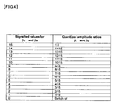
- FIG. 4 is a quantization table of gain factors ⁇ c and ⁇ d
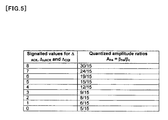
- FIG. 5 is a quantization table of ⁇ hs/ ⁇ c
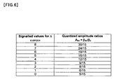
- FIG. 6 is a quantization table of ⁇ ec/ ⁇ c
- FIG. 7 is a quantization table of ⁇ ed/ ⁇ c.
- gain factors Bd, ⁇ ec, ⁇ ed1 and ⁇ ed3 are assigned to I side
- gain factors ⁇ c, ⁇ hs, Bed2 and ⁇ ed4 are assigned to Q side.
- FIG. 8 is a table showing assignment of IQ-multiplex to E-DPDCH.
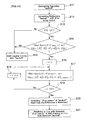
- FIG. 9 is a flow-chart showing an operation of the HSUPA signal-transmission system in accordance with the first exemplary embodiment of the present invention. Hereinbelow is explained the operation of the HSUPA signal-transmission system in accordance with the first exemplary embodiment of the present invention, with reference to FIG. 9 .
- eight channels DPCCH, DPDCH, HS-DPCCH, E-DPCCH, E-DPDCH1, E-DPDCH2, E-DPDCH3, and E-DPDCH4 are used in the HSUPA signal-transmission system in accordance with the first exemplary embodiment of the present invention.
- Each of gain factors ⁇ corresponding to signal-transmission data in each of channels is optimally determined and appointed in an upper layer in accordance with communication status as a gain factor illustrated in FIGs. 4 to 7 .
- the peak index calculator 301 calculates a peak index (step S1).
- the peak index calculator 301 calculates an average power indication A in accordance with the equation (1).
- A ⁇ c 2 + ⁇ d 2 + ⁇ hs 2 + ⁇ ec 2 + ⁇ ed ⁇ 1 2 + ⁇ ed ⁇ 2 2 + ⁇ ed ⁇ 3 2 + ⁇ ed ⁇ 4 2
- the peak index calculator 301 an IQ peak power indication B in accordance with the equation (2).
- the peak index calculator 301 calculates a peak index in accordance with the equation (3) (step S1).
- the coefficient selector 302 selects fitting coefficients X and Y out of a lookup table in accordance with a combination of gain factors ⁇ (step S2).
- FIG. 10 illustrates an example of a lookup table out of which the coefficient selector 302 selects fitting coefficients X and Y.
- a gain factor ⁇ c is greater than zero ( ⁇ c>0)
- a gain factor ⁇ d is equal to or greater than zero ( ⁇ d ⁇ 0)
- a gain factor ⁇ hs is equal to or greater than zero ( ⁇ hs ⁇ 0)
- a number of gain factors ⁇ ed (a number of E-DPDCHs) is equal to zero
- the power reduction calculator 303 calculates a reduction dB of maximum signal-transmission power in accordance with the following equation, based o a peak index C calculated by the peak index calculator 301 and the fitting coefficients X and Y selected by the coefficient selector 302 (step S3).
- the TXAGC calculator 304 calculates allowable maximum signal-transmission power in accordance with the following equation, based on the power reduction dB calculated by the power reduction calculator 303, for controlling signal-transmission power (step S4).
- FIG. 11 is a conceptional drawing showing the simulation results of a reduction in maximum signal-transmission power in Category in FIG. 10 , obtained by processing PA output signals transmitted fro the signal-transmission RF part 105, and FIG. 12 illustrates an example of the results of a reduction in Category 2 in FIG. 10 , obtained by the above-mentioned approximate calculation in the first exemplary embodiment of the present invention.
- the fitting coefficient X is set equal to 2
- the fitting coefficient Y is set equal to 0.22.
- the fitting coefficient X is equal principally to 1 or 2
- the fitting coefficient Y is principally in the range of 0 to 1 both inclusive.
- the fitting coefficients X and Y can be set equal to arbitrary figures by means of a non-volatile memory. It is possible to store optimally adjusted fitting coefficients X and Y into a non-volatile memory by actually measuring an adjacent channel leakage power ratio ACLR when the HSUPA signal-transmission system is actually mounted into a device.
- the HSUPA signal-transmission system in accordance with the first exemplary embodiment uses predetermined combinations of gain factors ⁇ , and makes it possible to approximately and accurately calculate a reduction in maximum signal-transmission power. Accordingly, it is no longer necessary to carry out complex calculation for processing signals, and it is possible to carry out signal processing at a high rate, and downsize a circuit. Since a reduction in maximum signal-transmission power can be accurately calculated though there is an enormous number of combinations of gain factors ⁇ , it is possible to avoid an adjacent channel leakage power ratio ACLR from being deteriorated, and prevent a cell area which a base station is able to cover from being wastefully narrowed.
- the first exemplary embodiment is applied to a signal-transmission system employing HSUPA.
- an object to which the first exemplary embodiment is applied is not to be limited to a signal-transmission system, but the first exemplary embodiment may be applied to a CDMA-type transmitter.
- the HSUPA signal-transmission system in accordance with the second exemplary embodiment of the present invention is identical in structure to the HSUPA signal-transmission system in accordance with the first exemplary embodiment of the present invention, illustrated in FIG. 1 , but the TXAGC controller 102 in the second exemplary embodiment of the present invention operates in a different manner from the TXAGC controller 102 in the first exemplary embodiment of the present invention.
- FIG. 1 similarly to the HSUPA signal-transmission system in accordance with the first exemplary embodiment of the present invention, eight channels DPCCH, DPDCH, HS-DPCCH, E-DPCCH, E-DPDCH1, E-DPDCH2, E-DPDCH3, and E-DPDCH4 are used in the HSUPA signal-transmission system in accordance with the second exemplary embodiment of the present invention.
- Each of gain factors ⁇ corresponding to signal-transmission data in each of channels is optimally determined and appointed in an upper layer in accordance with communication status as a gain factor illustrated in FIGs. 4 to 7 .
- 3GPP defines the " ⁇ ed_reduce" specification in which a gain factor Bed appointed by an upper layer varies slot by slot (3GPP Release 6 TS 25. 214 V6.7.1, 5.1.2.6).
- 3GPP defines a specification in which a gain factor Bed is reduced to zero in accordance with a TPC command controlled slot by slot,, though it depends on a combination of other channels (3GPP Release 6 TS 25. 214 V6. 7. 1, 5.1.2.6).
- the second exemplary embodiment of the present invention makes it possible to optimally calculate " ⁇ ed_reduce” into which consideration about a reduction following PAR (Peak to Average power Ratio) varying slot by slot is given, by virtue of approximate process for calculating a reduction in maximum signal-transmission power at a high rate and with high accuracy.
- PAR Peak to Average power Ratio
- FIG. 14 is a flow-chart showing an operation of the HSUPA signal-transmission system in accordance with the second exemplary embodiment of the present invention.
- an operation of the HSUPA signal-transmission system in accordance with the second exemplary embodiment is explained with reference to FIG. 14 .
- the TXAGC controller 102 calculates a reduction "backoff" in the same way as steps S1 to S3 having been explained in the first exemplary embodiment.
- the TXAGC controller 102 causes only a gain factor Bed among the gain factors ⁇ having been determined by an upper layer to vary, and calculates reductions "backoffi" for each of the gain factors Bed (step S 12).
- FIG. 15 is an example of a reduction table of " ⁇ ed_reduce”.
- the TXAGC controller 102 causes a gain factor Bed to vary as shown in indexes 0 to 29, and calculates a reduction "backoffi" for each of gain factors Bed.
- indexes 0 to 29 shown in FIG. 15 are just an example, and indexes are not to be limited to the indexes 0 to 29 shown in FIG. 15 .
- a reduction "backoffi" may be calculated with a gain factor Bed being varied more finely or more roughly.
- the TXAGC controller 102 judges whether a TPC command instructs an increase in signal-transmission power TPC by ⁇ tpc (step S13).
- the TXAGC controller 102 judges that the TPC command does not instruct an increase in signal-transmission power TPC by ⁇ tpc (NO in step S13), the TXAGC controller 102 controls maximum signal-transmission power in accordance with the reduction "backoff" calculated in step S11, similarly to step S4 shown in FIG. 9 (step S15).
- TXAGC controller 102 judges whether a difference calculated by subtracting both the reduction "backoff" calculated in step S11 and DPCCH power P DPCCH to which ⁇ tpc is added, from maximum signal-transmission power Max is smaller than signal-transmission power of DPDCH, HS-DPCCH, E-DPCCH and E-DPDCH, that is, 10 ⁇ log 10 ( ⁇ c 2 + ⁇ d 2 + ⁇ hs 2 + ⁇ ec 2 + k ⁇ ⁇ ed 2 ) wherein "k” indicates a coefficient determined in accordance with a number of E-DPDCHs (step S14).
- the TXAGC controller 102 controls maximum signal-transmission power in accordance with the reduction having been calculated in step S11, similarly to step S4 shown in FIG. 9 (step S15).
- the TXAGC controller 102 calculates a difference between a difference calculated by subtracting both the reduction "backoff 0" and DPCCH power P DPCCH to which ⁇ tpc is added from the maximum signal-transmission power Max, and signal-transmission power of DPDCH, HS-DPCCH, E-DPCCH and E-DPDCH, that is, 10 ⁇ log 10 ( ⁇ c 2 + ⁇ d 2 + ⁇ hs 2 + ⁇ ec 2 + k ⁇ ( ⁇ ed_reduce 0) 2 ) (step S17).
- the TXAGC controller 102 calculates a difference between allowable maximum signal-transmission power and total signal-transmission power.
- the TXAGC controller 102 calculates a difference between allowable maximum signal-transmission power and total signal-transmission power for each of Indexes 1 to 29 shown in FIG. 15 (steps S18, S19 and S17).
- the TXAGC controller 102 After calculating a difference between allowable maximum signal-transmission power and total signal-transmission power for each of Indexes 1 to 29, the TXAGC controller 102 selects, among " ⁇ ed_reduce”s and reductions, " ⁇ ed_reduce” and a reduction which do not cause total signal-transmission power to exceed allowable maximum signal-transmission power, and minimize a difference among the calculated differences, as " ⁇ ed_reduce” and a reduction to be used for a current slot (step S20).
- the TXAGC controller 102 give a weight to E-DPDCH with the selected " ⁇ ed_reduce", and controls maximum signal-transmission power in accordance with the selected reduction, similarly to step S9 shown in FIG. 9 (step S21).
- the HSUPA signal-transmission system in accordance with the second exemplary embodiment makes it possible to calculate each of reductions at a high rate with a gain factor Bed being varied, and thus, determine " ⁇ ed_reduce" to which consideration about a reduction is given. Accordingly, it is possible to effectively prevent an adjacent channel leakage power ratio ACLR from being deteriorated, and further prevent a cell area covered by a base station from being narrowed.
- An operation of a user equipment UE to be carried out in accordance with the flow-charts shown in FIGs. 9 and 14 can be accomplished by storing a program into a storage medium such as ROM in a user equipment UE, causing a computer as CPU (central processing unit) to read the program, and causing the computer to execute the program.
- a storage medium such as ROM in a user equipment UE
- CPU central processing unit
Landscapes
- Engineering & Computer Science (AREA)
- Computer Networks & Wireless Communication (AREA)
- Signal Processing (AREA)
- Mobile Radio Communication Systems (AREA)
- Transmitters (AREA)
Abstract
Description
- The invention relates to an apparatus for controlling signal-transmission power, a mobile station including the apparatus for controlling signal-transmission power, a method of controlling signal-transmission power, and a program for carrying out the method, and more particularly to such an apparatus, such a mobile station, such a method, and such a program all for controlling maximum signal-transmission power among power for transmitting a plurality of signals multiplexed with one another.
- In a field of communication of a mobile such as a mobile phone, 3GPP (3rd Generation Partnership Project) defines and suggests a standard for W-CDMA (Wideband-Code Division Multiple Access). Furthermore, as a method of transferring data at a high rate in an up-link channel, that is, from a user equipment UE to a base station, HSUPA (High Speed Uplink Packet Access) is additionally defined.
-
FIG. 16 is a block diagram illustrating a structure of a conventional HSUPA signal-transmission system. - As illustrated in
FIG. 16 , the conventional HSUPA signal-transmission system comprises adiffuser 101, aFIR filter 103, a DAC (Digital to Analog converter) 104, and a signal-transmission RF (Radio Frequency)part 105. - As illustrated in
FIG. 16 , in the HSUPA signal-transmission system, E-DPDCH (Enhanced Dedicated Physical Data Channel) is input into thediffuser 101 as a channel for transferring data therethrough, and E-DPCCH (Enhanced Dedicated Physical Control Channel) is input into thediffuser 101 as a channel for transferring control data therethrough. - These E-DPDCH and E-DPCCH are additionally code-multiplexed with a conventional W-CDMA Uplink channel, accomplishing high-rate data communication (non-patent reference 1).
- As illustrated in
FIG. 16 , four or less code-multiplexing (E-DPDCH4, E-DPDCH3, E-DPDCH2, E-DPDCH1) is defined with respect to E-DPDCH (non-patent reference 2). - Furthermore, HS-DPCCH (High Speed Dedicated Physical Control Channel) used for HSDPA (High Speed Downlink Packet Access) is input into the
diffuser 101 as a channel for transferring information about data re-transmission. HS-DPCCH is additionally code-multiplexed with a conventional W-CDMA Uplink channel. - If a number of channels to be code-multiplexed with W-CDMA channel were increased as mentioned above, PAR (Peak to Average power Ratio) defined as a ratio between peak power and average power in transmission of a signal would be increased, resulting in that power amplifier PA is deformed, and thus, ACLR (Adjacent Channel Leakage power Ratio) is deteriorated.
- In 3GPP, there is defined a specification in which a number of channels to be multiplexed in a signal-transmission circuit equipped in a user equipment UE, and maximum signal-transmission power is fixedly reduced, if HSUPA (High Speed Uplink Packet Access) is not used (not-patent reference 3).
- As a reduction (a back-off) of the maximum signal-transmission power, three fixed constants are stored in a lookup table in accordance only with a gain factor (ßc/ßd).
Non-patent reference 1:3GPP Release 6 TS 25.211 V6.7.0, 5.2.1.3
Non-patent reference 2:3GPP Release 6 TS 25.213 V6.4.0, 4.2
Non-patent reference 3:3GPP Release 5 TS 25.101 V5.d.0, 6.2.2 - On the other hand, if HSUPA (High Speed Uplink Packet Access) is used, a number of channels to be multiplexed is further increased, resulting in millions of a possible combination of gain factors β. Thus, if a lookup table were used in order to determine a reduction in maximum signal-transmission power in a conventional process, it would be difficult to carry out simply grouping with the result of an increase in an error in a reduction in maximum signal-transmission power.
- In order to accurately calculate a reduction in maximum signal-transmission power, it would be necessary to sample waveforms of signals for a certain period of time in a path downstream of the FIR (Finite Impulse Response)
filter 103, and process the results of sampling. However, it takes a lot of burden to process the results of sampling, and accordingly, a circuit structure is complex and a circuit size is increased in order to accomplish processing the results of sampling immediately prior to transmission of a signal. - If a reduction in maximum signal-transmission power were small relative to a peak, ACLR (Adjacent Channel Leakage power Ratio) would be deteriorated, and, in contrast, if a reduction in maximum signal-transmission power were wastefully high relative to a peak, there would be caused a problem that a cell area covered by a base station is narrowed.
- Thus, there is a need for a method of accurately and readily calculating an optimal reduction in maximum signal-transmission power.
- In view of the above-mentioned problems, it is an object of the present invention to provide an apparatus for controlling signal-transmission power, which makes it possible to accurately and readily calculate an optimal reduction in maximum signal-transmission power to prevent deterioration of ACLR (Adjacent Channel Leakage power Ratio), and prevent a cell area covered by a base station from being wastefully narrowed.
- It is further an object of the present invention to provide a mobile station, a method of controlling signal-transmission power, and a program for carrying out the method, all of which make it possible to do the same.
- In order to accomplish the above-mentioned objects, the present invention provides a signal-transmission power controlling apparatus for controlling maximum signal-transmission power among power for transmitting a plurality of signals multiplexed with one another, including reduction-calculating means for calculating a reduction in the maximum signal-transmission power in accordance with a peak index and a coefficient, the peak index being calculated based on gain factors used for giving a weight to each of the signals, the peak index providing an indication of a ratio between peak power and average power in a signal to be transmitted, the coefficient being predetermined in accordance with a combination of the gain factors, and controlling means for controlling the maximum signal-transmission power in accordance with the reduction calculated by the reduction-calculating means.
- It is preferable that the reduction-calculating means includes peak-index calculating means which selects, as an average power indication, a square root of a sum of squares of each of the gain factors, and, as a peak power indication, a square root of a sum of (a) square of a sum of gain factors of channels assigned to I-phase among the gain factors, and (b) square of a sum of gain factors of channels assigned to Q-phase among the factors, and calculates, as the peak index, a ratio between the peak power indication and the average power indication.
- It is preferable that the reduction-calculating means calculates the reduction in accordance with an equation:
-

wherein C indicates the peak index, and each of X and Y indicates the coefficient.
It is preferable that the reduction-calculating means calculates a reduction in each of cases in which a gain factor Bed of E-DPDCH (Enhanced-Dedicated Physical Data Channel) among the gain factors is varied, and determines the gain factor Bed and a reduction which minimize a difference between an allowable maximum signal-transmission power (allowable maximum signal-transmission power = maximum signal-transmission power - reduction) and total power in each of the cases. - It is preferable that the controlling means gives a weight to the E-DPDCH with the gain factor Bed determined by the reduction-calculating means, and controls the maximum signal-transmission power in accordance with the reduction determined by the reduction-calculating means.
- The above-mentioned signal-transmission power-controlling apparatus may be mounted in a mobile station, for instance.
- The mobile station may be comprised of a mobile phone, for instance.
- The present invention further provides a method of controlling maximum signal-transmission power among power for transmitting a plurality of signals multiplexed with one another, including a reduction-calculating step of calculating a reduction in the maximum signal-transmission power in accordance with a peak index and a coefficient, the peak index being calculated based on gain factors used for giving a weight to each of the signals, the peak index providing an indication of a ratio between peak power and average power in a signal to be transmitted, the coefficient being predetermined in accordance with a combination of the gain factors, and a controlling step of controlling the maximum signal-transmission power in accordance with the reduction calculated in the reduction-calculating step.
- It is preferable that the reduction-calculating step includes a step of selecting, as an average power indication, a square root of a sum of squares of each of the gain factors, and, as a peak power indication, a square root of a sum of (a) square of a sum of gain factors of channels assigned to I-phase among the gain factors, and (b) square of a sum of gain factors of channels assigned to Q-phase among the factors, and calculating, as the peak index, a ratio between the peak power indication and the average power indication.
- It is preferable that the reduction-calculating step includes a step of calculating the reduction in accordance with an equation:
-

wherein C indicates the peak index, and each of X and Y indicates the coefficient.
It is preferable that the reduction-calculating steps includes a step of calculating a reduction in each of cases in which a gain factor Bed of E-DPDCH (Enhanced-Dedicated Physical Data Channel) among the gain factors is varied, and determining the gain factor Bed and a reduction which minimize a difference between an allowable maximum signal-transmission power (allowable maximum signal-transmission power = maximum signal-transmission power - reduction) and total power in each of the cases. - It is preferable that the controlling step includes a step of giving a weight to the E-DPDCH with the gain factor Bed determined in the reduction-calculating step, and controlling the maximum signal-transmission power in accordance with the reduction determined in the reduction-calculating step.
- The present invention further provides a program for causing a computer to carry out a method of controlling maximum signal-transmission power among power for transmitting a plurality of signals multiplexed with one another, steps executed by the computer in accordance with the program including a reduction-calculating step of calculating a reduction in the maximum signal-transmission power in accordance with a peak index and a coefficient, the peak index being calculated based on gain factors used for giving a weight to each of the signals, the peak index providing an indication of a ratio between peak power and average power in a signal to be transmitted, the coefficient being predetermined in accordance with a combination of the gain factors, and a controlling step of controlling the maximum signal-transmission power in accordance with the reduction calculated in the reduction-calculating step.
- It is preferable that the reduction-calculating step includes a step of selecting, as an average power indication, a square root of a sum of squares of each of the gain factors, and, as a peak power indication, a square root of a sum of (a) square of a sum of gain factors of channels assigned to I-phase among the gain factors, and (b) square of a sum of gain factors of channels assigned to Q-phase among the factors, and calculating, as the peak index, a ratio between the peak power indication and the average power indication.
- It is preferable that the reduction-calculating step includes a step of calculating the reduction in accordance with an equation:
-

wherein C indicates the peak index, and each of X and Y indicates the coefficient.
It is preferable that the reduction-calculating steps includes a step of calculating a reduction in each of cases in which a gain factor Bed of E-DPDCH (Enhanced-Dedicated Physical Data Channel) among the gain factors is varied, and determining the gain factor Bed and a reduction which minimize a difference between an allowable maximum signal-transmission power (allowable maximum signal-transmission power = maximum signal-transmission power - reduction) and total power in each of the cases. - It is preferable that the controlling step includes a step of giving a weight to the E-DPDCH with the gain factor Bed determined in the reduction-calculating step, and controlling the maximum signal-transmission power in accordance with the reduction determined in the reduction-calculating step.
- In accordance with the present invention, as mentioned above, a peak index providing an indication of a ratio between peak power and average power in a signal to be transmitted is calculated based on gain factors, and a reduction in maximum signal-transmission power is calculated in accordance with the thus calculated peak index and a coefficient predetermined in accordance with a combination of the gain factors. Thus, it is possible to approximately calculate a reduction in maximum signal-transmission power with high accuracy without carrying out complex calculation for processing signals.
-
- [
FIG. 1] FIG. 1 is a block diagram illustrating a structure of the HSUPA signal-transmission system in accordance with the first exemplary embodiment of the present invention. - [
FIG. 2] FIG. 2 is a block diagram illustrating a structure of a diffuser which is a part of the HSUPA signal-transmission system in accordance with the first exemplary embodiment of the present invention. - [
FIG. 3] FIG. 3 is a block diagram illustrating a structure of a TXAGC controller which is a part of the HSUPA signal-transmission system in accordance with the first exemplary embodiment of the present invention. - [
FIG. 4] FIG. 4 illustrates a quantization table of gain factors ßc and Bd. - [
FIG. 5] FIG. 5 illustrates a quantization table of ßhs/ßc. - [
FIG. 6] FIG. 6 illustrates a quantization table of ßec/ßc. - [
FIG. 7] FIG. 7 illustrates a quantization table of ßed/ßc. - [
FIG. 8] FIG. 8 illustrates assignment of IQ-multiplex to E-DPDCH. - [
FIG. 9] FIG. 9 is a flow-chart showing the operation of the HSUPA signal-transmission system in accordance with the first exemplary embodiment of the present invention. - [
FIG. 10] FIG. 10 illustrates an example of a coefficient selector which is a part of the TXAGC controller. - [
FIG. 11] FIG. 11 illustrates the simulation result of a reduction inCategory 2 in the lookup table illustrated inFIG. 10 , obtained by processing PA output signals transmitted from the signal-transmission RF part. - [
FIG. 12] FIG. 12 illustrates an example of the results of a reduction inCategory 2 in the lookup table illustrated inFIG. 10 , obtained by approximate calculation carried out in the first exemplary embodiment of the present invention. - [
FIG. 13] FIG. 13 illustrates "ßed_reduce" in which a gain factor Bed varies slot by slot. - [
FIG. 14] FIG. 14 is a flow-chart showing the operation of the HSUPA signal-transmission system in accordance with the second exemplary embodiment of the present invention. - [
FIG. 15] FIG. 15 illustrates an example of a table showing a reduction in maximum signal-transmission power for each of "ßed_reduce". - [
FIG. 16] FIG. 16 is a block diagram illustrating a structure of the conventional HSUPA signal-transmission system. -
- 101 Diffuser
- 102 TXAGC controller
- 103 FIR filter
- 104 DAC (Digital/Analog converter)
- 105 Signal-transmission RF part
- 106 TXAGC signal
- 201-1 to 201-8 Computing units
- 202-1 to 202-8 Computing units
- 203a, 203b Adders
- 204, 206 Computing units
- 205 Adder
- 300 Reduction calculator
- 301 Peak index calculator
- 302 Coefficient selector
- 303 Power reduction calculator
- 304 TXAGC calculator
-
FIG. 1 is a block diagram illustrating a structure of a HSUPA signal-transmission system in accordance with the first exemplary embodiment of the present invention. - As illustrated in
FIG. 1 , the HSUPA signal-transmission system in accordance with the first exemplary embodiment of the present invention is comprised of adiffuser 101, a TXAGC (signal-transmission Auto Gain Control)controller 102, aFIR filter 103, a DAC (Digital/Analog Convertor) 104, and a signal-transmission RF (Radio Frequency)part 105. - The HSUPA signal-transmission system in accordance with the first exemplary embodiment is applied, for instance, to a mobile station (for instance, a mobile phone set) in a mobile communication system.
-
FIG. 2 is a block diagram illustrating a structure of thediffuser 101 in the HSUPA signal-transmission system in accordance with the first exemplary embodiment. - As illustrated in
FIG. 2 , thediffuser 101 comprises eight computing units 201-1 to 201-8, eight computing units 202-1 to 202-8, twoadders computing unit 204, anadder 205, and acomputing unit 206. - As illustrated in
FIGs. 1 and2 , signals in channels DPCCH, DPDCH, HS-DPCCH, E-DPCCH and E-DPDCH1 to E-DPDCH4 are code-multiplexed with one another, and then, transmitted in the HSUPA signal-transmission system in accordance with the first exemplary embodiment. The signals in E-DPDCH3, E-DPDCH1, E-DPCCH, DPDCH, E-DPDCH4, E-DPDCH2, HS-DPCCH and DPCCH are diffused in the computing units 201-1 to 201-8 with channelization codes Ced3, Ced1, Cec, Cd, Ced4, Ced2, Chs and Cc, respectively. Then, a weight is given to the signals in the computing units 202-1 to 202-8 with gain factors (parameters) βed3, βed1, βec, βd, βed4, βed2, βhs and βc, respectively. - The
adder 203a adds output signals transmitted from the computing units 202-1 to 202-4 to one another, and outputs the sum as I branch. - The
adder 203b adds output signals transmitted from the computing units 202-5 to 202-8 to one another, and outputs the sum as Q branch. - The
computing unit 204 multiplies an output signal transmitted from theadder 203b by an imaginary number j. - The
adder 205 adds an output signal transmitted from theadder 203a to an output signal transmitted from thecomputing unit 204. - An output signal transmitted from the
adder 205 is again diffused in thecomputing unit 206 with a scrambling code Scr. - The
FIR filter 103 is comprised of a root-raised cosine filter used for limiting a band. - The DAC (Digital/Analog Converter) 104 converts a digital signal transmitted from the
FIR filter 103 to an analog signal. - The signal-
transmission RF part 105 up-converts a frequency of the analog signal output from the DAC (Digital/Analog Converter) 104, amplifies the analog signal by means of a power amplifier PA (not illustrated), and transmits the analog signal as a radio signal through an antenna (not illustrated). - The signal-
transmission RF part 105 has a function of receiving aTXAGC signal 106 from theTXAGC controller 102, and controlling a gain thereof. - The
TXAGC controller 102 calculates power at which a signal is transmitted, and transmits aTXAGC signal 106 to the signal-transmission RF part 105 for controlling the signal-transmission RF part 105. -
FIG. 3 is a block diagram illustrating a structure of theTXAGC controller 102 in the HSUPA signal-transmission system in accordance with the first exemplary embodiment. - As illustrated in
FIG. 3 , theTXAGC controller 102 comprises areduction calculator 300, and aTXAGC calculator 304. - The
reduction calculator 300 comprises apeak index calculator 301, acoefficient selector 302, and apower reduction calculator 303. - The
peak index calculator 301 includes a computing circuit which calculates a peak index as an indication of a peak to average power ratio (PAR) in accordance with both gain factors β in channels and assignment of IQ mapping in channels. - The
coefficient selector 302 includes a lookup table rewritable by means of a non-volatile memory. The lookup table stores therein fitting coefficients X and Y each categorized in accordance with a combination of gain factors B. - The
power reduction calculator 303 includes a computing circuit which solves an approximate equation in accordance with a peak index calculated by thepeak index calculator 301 and fitting coefficients selected by thecoefficient selector 302. - The
TXAGC calculator 304 includes a circuit which calculates allowable maximum signal-transmission power defined by subtracting a reduction calculated by thepower reduction calculator 303 from maximum signal-transmission power unique to a user equipment UE (allowable maximum signal-transmission power = maximum signal-transmission power - reduction). - Each of gain factors β is defined in 3GPP based on βc (see the non-patent reference 2).
- Each of
FIGs. 4 to 7 is a table showing gain factors B. Specifically,FIG. 4 is a quantization table of gain factors βc and βd,FIG. 5 is a quantization table of βhs/βc,FIG. 6 is a quantization table of βec/βc, andFIG. 7 is a quantization table of βed/βc. - In the example illustrated in
FIG. 2 , gain factors Bd, βec, βed1 and βed3 (DPDCH, E-DPCCH, E-DPDCH1 and E-DPDCH3) are assigned to I side, and gain factors βc, βhs, Bed2 and βed4 (DPCCH, HS-DPCCH, E-DPDCH2 and E-DPDCH4) are assigned to Q side. - If HS-DPCCH does not exist, but DPDCH exists, as illustrated in
FIG. 8 , a specification in which IQ assignment of a gain factor Bed is reversed is defined in 3GPP (see the non-patent reference 2).FIG. 8 is a table showing assignment of IQ-multiplex to E-DPDCH. -
FIG. 9 is a flow-chart showing an operation of the HSUPA signal-transmission system in accordance with the first exemplary embodiment of the present invention. Hereinbelow is explained the operation of the HSUPA signal-transmission system in accordance with the first exemplary embodiment of the present invention, with reference toFIG. 9 . - As illustrated in
FIGs. 1 and2 , eight channels DPCCH, DPDCH, HS-DPCCH, E-DPCCH, E-DPDCH1, E-DPDCH2, E-DPDCH3, and E-DPDCH4 are used in the HSUPA signal-transmission system in accordance with the first exemplary embodiment of the present invention. - Each of gain factors β corresponding to signal-transmission data in each of channels is optimally determined and appointed in an upper layer in accordance with communication status as a gain factor illustrated in
FIGs. 4 to 7 . - In
FIG. 9 , on determination of a combination of gain factors β in an upper layer, thepeak index calculator 301 calculates a peak index (step S1). - Specifically, the
peak index calculator 301 calculates an average power indication A in accordance with the equation (1). -

- Furthermore, the
peak index calculator 301 an IQ peak power indication B in accordance with the equation (2). -

- It should be noted that, as mentioned above, the assignment of gain factor Bed mapping to IQ varies in accordance with
FIG. 8 . - Furthermore, the
peak index calculator 301 calculates a peak index in accordance with the equation (3) (step S1). -

- The
coefficient selector 302 selects fitting coefficients X and Y out of a lookup table in accordance with a combination of gain factors β (step S2). -
FIG. 10 illustrates an example of a lookup table out of which thecoefficient selector 302 selects fitting coefficients X and Y. - For instance, if a gain factor βc is greater than zero (βc>0), a gain factor βd is equal to or greater than zero (βd≧0), a gain factor βhs is equal to or greater than zero (βhs≧0), and a number of gain factors βed (a number of E-DPDCHs) is equal to zero, x0 and y0 are selected out of
Category 1 as. fitting coefficients X and Y. - The
power reduction calculator 303 calculates a reduction dB of maximum signal-transmission power in accordance with the following equation, based o a peak index C calculated by thepeak index calculator 301 and the fitting coefficients X and Y selected by the coefficient selector 302 (step S3). -

- The
TXAGC calculator 304 calculates allowable maximum signal-transmission power in accordance with the following equation, based on the power reduction dB calculated by thepower reduction calculator 303, for controlling signal-transmission power (step S4). - Allowable maximum signal-transmission power = Maximum signal-transmission power - Reduction
FIG. 11 is a conceptional drawing showing the simulation results of a reduction in maximum signal-transmission power in Category inFIG. 10 , obtained by processing PA output signals transmitted fro the signal-transmission RF part 105, andFIG. 12 illustrates an example of the results of a reduction inCategory 2 inFIG. 10 , obtained by the above-mentioned approximate calculation in the first exemplary embodiment of the present invention. - In
FIG. 12 , the fitting coefficient X is set equal to 2, and the fitting coefficient Y is set equal to 0.22. - Comparing
FIGs. 11 and12 to each other, the simulation results inFIG. 11 is almost coincident with the results of the approximate calculation carried out in accordance with the first exemplary embodiment of the present invention. This means that the first exemplary embodiment of the present invention makes it possible to accurately calculate a reduction in maximum signal-transmission power. - It is possible to cover an enormous number of combinations of gain factors β with a practical number of categories by carrying out fitting approach so as to approach the simulation results illustrated in
FIG. 11 , or by categorizing fitting coefficients X and Y, and determining fitting coefficients X and Y in each of categories. - In the above-mentioned equations used for calculating a reduction, the fitting coefficient X is equal principally to 1 or 2, and the fitting coefficient Y is principally in the range of 0 to 1 both inclusive.
- The fitting coefficients X and Y can be set equal to arbitrary figures by means of a non-volatile memory. It is possible to store optimally adjusted fitting coefficients X and Y into a non-volatile memory by actually measuring an adjacent channel leakage power ratio ACLR when the HSUPA signal-transmission system is actually mounted into a device.
- The HSUPA signal-transmission system in accordance with the first exemplary embodiment uses predetermined combinations of gain factors β, and makes it possible to approximately and accurately calculate a reduction in maximum signal-transmission power. Accordingly, it is no longer necessary to carry out complex calculation for processing signals, and it is possible to carry out signal processing at a high rate, and downsize a circuit. Since a reduction in maximum signal-transmission power can be accurately calculated though there is an enormous number of combinations of gain factors β, it is possible to avoid an adjacent channel leakage power ratio ACLR from being deteriorated, and prevent a cell area which a base station is able to cover from being wastefully narrowed.
- The first exemplary embodiment is applied to a signal-transmission system employing HSUPA. However, it should be noted that an object to which the first exemplary embodiment is applied is not to be limited to a signal-transmission system, but the first exemplary embodiment may be applied to a CDMA-type transmitter.
- The HSUPA signal-transmission system in accordance with the second exemplary embodiment of the present invention is identical in structure to the HSUPA signal-transmission system in accordance with the first exemplary embodiment of the present invention, illustrated in
FIG. 1 , but theTXAGC controller 102 in the second exemplary embodiment of the present invention operates in a different manner from theTXAGC controller 102 in the first exemplary embodiment of the present invention. - As illustrated in
FIG. 1 , similarly to the HSUPA signal-transmission system in accordance with the first exemplary embodiment of the present invention, eight channels DPCCH, DPDCH, HS-DPCCH, E-DPCCH, E-DPDCH1, E-DPDCH2, E-DPDCH3, and E-DPDCH4 are used in the HSUPA signal-transmission system in accordance with the second exemplary embodiment of the present invention. - Each of gain factors β corresponding to signal-transmission data in each of channels is optimally determined and appointed in an upper layer in accordance with communication status as a gain factor illustrated in
FIGs. 4 to 7 . - In particular, with respect to a gain factor Bed, 3GPP defines the "βed_reduce" specification in which a gain factor Bed appointed by an upper layer varies slot by slot (
3GPP Release 6TS 25. 214 V6.7.1, 5.1.2.6). - In the "βed_reduce" specification, when DPCCH power as standard power increases only by Δ tpc in accordance with a TPC (Transmit Power Control) command controlled slot by slot, and total signal-transmission power exceeds allowable maximum signal-transmission power (allowable maximum signal-transmission power = maximum signal-transmission power - reduction), only a gain factor Bed, that is, only E-DPDCH power is reduced.
- 3GPP defines a specification in which a gain factor Bed is reduced to zero in accordance with a TPC command controlled slot by slot,, though it depends on a combination of other channels (
3GPP Release 6TS 25. 214 V6. 7. 1, 5.1.2.6). - However, if there occurs "βed_reduce" shown in
FIG. 13 , the results of the reduction illustrated inFIGs. 11 and12 , a reduction in maximum signal-transmission power varies in dependence on a gain factor Bed. Accordingly, it is not possible in this case to follow fluctuation of PAR (Peak to Average power Ratio) varying slot by slot, if only allowable maximum signal-transmission power is calculated based on a reduction calculated in accordance with a gain factor Bed appointed by an upper layer. - The second exemplary embodiment of the present invention makes it possible to optimally calculate "βed_reduce" into which consideration about a reduction following PAR (Peak to Average power Ratio) varying slot by slot is given, by virtue of approximate process for calculating a reduction in maximum signal-transmission power at a high rate and with high accuracy.
-
FIG. 14 is a flow-chart showing an operation of the HSUPA signal-transmission system in accordance with the second exemplary embodiment of the present invention. Hereinbelow, an operation of the HSUPA signal-transmission system in accordance with the second exemplary embodiment is explained with reference toFIG. 14 . - In
FIG. 14 , on determination of a combination of gain factors β by an upper layer, theTXAGC controller 102 calculates a reduction "backoff" in the same way as steps S1 to S3 having been explained in the first exemplary embodiment. - Then, the
TXAGC controller 102 causes only a gain factor Bed among the gain factors β having been determined by an upper layer to vary, and calculates reductions "backoffi" for each of the gain factors Bed (step S 12). -
FIG. 15 is an example of a reduction table of "βed_reduce". - As illustrated in
FIG. 15 , theTXAGC controller 102 causes a gain factor Bed to vary as shown inindexes 0 to 29, and calculates a reduction "backoffi" for each of gain factors Bed. - It should be noted that the
indexes 0 to 29 shown inFIG. 15 are just an example, and indexes are not to be limited to theindexes 0 to 29 shown inFIG. 15 . For instance, a reduction "backoffi" may be calculated with a gain factor Bed being varied more finely or more roughly. - Then, the
TXAGC controller 102 judges whether a TPC command instructs an increase in signal-transmission power TPC by Δtpc (step S13). - If the
TXAGC controller 102 judges that the TPC command does not instruct an increase in signal-transmission power TPC by Δtpc (NO in step S13), theTXAGC controller 102 controls maximum signal-transmission power in accordance with the reduction "backoff" calculated in step S11, similarly to step S4 shown inFIG. 9 (step S15). - If
TXAGC controller 102 judges that the TPC command instructs an increase in signal-transmission power TPC by Δtpc (YES in step S13), theTXAGC controller 102 judges whether a difference calculated by subtracting both the reduction "backoff" calculated in step S11 and DPCCH power PDPCCH to which Δtpc is added, from maximum signal-transmission power Max is smaller than signal-transmission power of DPDCH, HS-DPCCH, E-DPCCH and E-DPDCH, that is, 10 × log10(βc2 + βd2 + βhs2 + βec2 + k × βed2) wherein "k" indicates a coefficient determined in accordance with a number of E-DPDCHs (step S14). - In other words, whether total signal-transmission power exceeds allowable maximum signal-transmission power (allowable maximum signal-transmission power = maximum signal-transmission power - reduction) is judged when DPCCH power increases by Δtpc.
- If a difference calculated by subtracting both the reduction "backoff" and DPCCH power PDPCCH to which Δtpc is added from maximum signal-transmission power Max is not smaller than signal-transmission power of DPDCH, HS-DPCCH, E-DPCCH and E-DPDCH, that is, if maximum signal-transmission power does not exceed allowable maximum signal-transmission power (NO in step S14), there does not occur "βed_reduce", and hence, a reduction does not vary. Thus, the
TXAGC controller 102 controls maximum signal-transmission power in accordance with the reduction having been calculated in step S11, similarly to step S4 shown inFIG. 9 (step S15). - If a difference calculated by subtracting both the reduction "backoff" and DPCCH power PDPCCH to which Δtpc is added from maximum signal-transmission power Max is smaller than signal-transmission power of DPDCH, HS-DPCCH, E-DPCCH and E-DPDCH, that is, if maximum signal-transmission power exceeds allowable maximum signal-transmission power (YES in step S14), the
TXAGC controller 102 sets "i" to be equal to zero (i = 0) (step S16) to select "βed_reduce 0" and a reduction "backoff 0" out ofIndex 0 in the table illustrated inFIG. 15 . Then, theTXAGC controller 102 calculates a difference between a difference calculated by subtracting both the reduction "backoff 0" and DPCCH power PDPCCH to which Δtpc is added from the maximum signal-transmission power Max, and signal-transmission power of DPDCH, HS-DPCCH, E-DPCCH and E-DPDCH, that is, 10 × log10(βc2 + βd2 + βhs2 + βec2 + k × (βed_reduce 0)2) (step S17). - That is, the
TXAGC controller 102 calculates a difference between allowable maximum signal-transmission power and total signal-transmission power. - The
TXAGC controller 102 calculates a difference between allowable maximum signal-transmission power and total signal-transmission power for each ofIndexes 1 to 29 shown inFIG. 15 (steps S18, S19 and S17). - After calculating a difference between allowable maximum signal-transmission power and total signal-transmission power for each of
Indexes 1 to 29, theTXAGC controller 102 selects, among "βed_reduce"s and reductions, "βed_reduce" and a reduction which do not cause total signal-transmission power to exceed allowable maximum signal-transmission power, and minimize a difference among the calculated differences, as "βed_reduce" and a reduction to be used for a current slot (step S20). - Then, the
TXAGC controller 102 give a weight to E-DPDCH with the selected "βed_reduce", and controls maximum signal-transmission power in accordance with the selected reduction, similarly to step S9 shown inFIG. 9 (step S21). - The conventional process in which waveforms of signals to be transmitted downstream of the
FIR filter 103 are sampled for a certain period of time, and a reduction in maximum signal-transmission power is obtained by processing the sampled signals is accompanied with a problem that it cannot follow a gain factor Bed varying in line with fluctuation of DPCCH power caused slot by slot by a TPC command. - In contrast, the HSUPA signal-transmission system in accordance with the second exemplary embodiment makes it possible to calculate each of reductions at a high rate with a gain factor Bed being varied, and thus, determine "βed_reduce" to which consideration about a reduction is given. Accordingly, it is possible to effectively prevent an adjacent channel leakage power ratio ACLR from being deteriorated, and further prevent a cell area covered by a base station from being narrowed.
- Furthermore, since signal-transmission power can be effectively utilized, it is possible to enhance a throughput.
- An operation of a user equipment UE to be carried out in accordance with the flow-charts shown in
FIGs. 9 and14 can be accomplished by storing a program into a storage medium such as ROM in a user equipment UE, causing a computer as CPU (central processing unit) to read the program, and causing the computer to execute the program.
Claims (17)
- A signal-transmission power controlling apparatus for controlling maximum signal-transmission power among power for transmitting a plurality of signals multiplexed with one another, comprising:reduction-calculating means for calculating a reduction in said maximum signal-transmission power in accordance with a peak index and a coefficient, said peak index being calculated based on gain factors used for giving a weight to each of said signals, said peak index providing an indication of a ratio between peak power and average power in a signal to be transmitted, said coefficient being predetermined in accordance with a combination of said gain factors; andcontrolling means for controlling said maximum signal-transmission power in accordance with said reduction calculated by said reduction-calculating means.
- The signal-transmission power-controlling apparatus as set forth in claim 1, wherein said reduction-calculating means includes peak-index calculating means which selects, as an average power indication, a square root of a sum of squares of each of said gain factors, and, as a peak power indication, a square root of a sum of (a) square of a sum of gain factors of channels assigned to I-phase among said gain factors, and (b) square of a sum of gain factors of channels assigned to Q-phase among said factors, and calculates, as said peak index, a ratio between said peak power indication and said average power indication.
- The signal-transmission power-controlling apparatus as set forth in claim 1 or 2, wherein said reduction-calculating means calculates said reduction in accordance with an equation:

wherein C indicates said peak index, and each of X and Y indicates said coefficient. - The signal-transmission power-controlling apparatus as set forth in any one of claims 1 to 3, wherein said reduction-calculating means calculates a reduction in each of cases in which a gain factor Bed of E-DPDCH (Enhanced-Dedicated Physical Data Channel) among said gain factors is varied, and determines said gain factor Bed and a reduction which minimize a difference between an allowable maximum signal-transmission power (allowable maximum signal-transmission power = maximum signal-transmission power - reduction) and total power in each of said cases.
- The signal-transmission power-controlling apparatus as set forth in claim 4, wherein said controlling means gives a weight to said E-DPDCH with said gain factor Bed determined by said reduction-calculating means, and controls said maximum signal-transmission power in accordance with said reduction determined by said reduction-calculating means.
- A mobile station including a signal-transmission power-controlling apparatus as set forth in any one of claims 1 to 5.
- The mobile station as set forth in claim 6, wherein said mobile station is comprised of a mobile phone.
- A method of controlling maximum signal-transmission power among power for transmitting a plurality of signals multiplexed with one another, comprising:a reduction-calculating step of calculating a reduction in said maximum signal-transmission power in accordance with a peak index and a coefficient, said peak index being calculated based on gain factors used for giving a weight to each of said signals, said peak index providing an indication of a ratio between peak power and average power in a signal to be transmitted, said coefficient being predetermined in accordance with a combination of said gain factors; anda controlling step of controlling said maximum signal-transmission power in accordance with said reduction calculated in said reduction-calculating step.
- The method as set forth in claim 8, wherein said reduction-calculating step includes a step of selecting, as an average power indication, a square root of a sum of squares of each of said gain factors, and, as a peak power indication, a square root of a sum of (a) square of a sum of gain factors of channels assigned to I-phase among said gain factors, and (b) square of a sum of gain factors of channels assigned to Q-phase among said factors, and calculating, as said peak index, a ratio between said peak power indication and said average power indication.
- The method as set forth in claim 8 or 9, wherein said reduction-calculating step includes a step of calculating said reduction in accordance with an equation:

wherein C indicates said peak index, and each of X and Y indicates said coefficient. - The method as set forth in any one of claims 8 to 10, wherein said reduction-calculating steps includes a step of calculating a reduction in each of cases in which a gain factor Bed of E-DPDCH (Enhanced-Dedicated Physical Data Channel) among said gain factors is varied, and determining said gain factor Bed and a reduction which minimize a difference between an allowable maximum signal-transmission power (allowable maximum signal-transmission power = maximum signal-transmission power - reduction) and total power in each of said cases.
- The method as set forth in claim 11, wherein said controlling step includes a step of giving a weight to said E-DPDCH with said gain factor Bed determined in said reduction-calculating step, and controlling said maximum signal-transmission power in accordance with said reduction determined in said reduction-calculating step.
- A program for causing a computer to carry out a method of controlling maximum signal-transmission power among power for transmitting a plurality of signals multiplexed with one another, steps executed by said computer in accordance with said program including:a reduction-calculating step of calculating a reduction in said maximum signal-transmission power in accordance with a peak index and a coefficient, said peak index being calculated based on gain factors used for giving a weight to each of said signals, said peak index providing an indication of a ratio between peak power and average power in a signal to be transmitted, said coefficient being predetermined in accordance with a combination of said gain factors; anda controlling step of controlling said maximum signal-transmission power in accordance with said reduction calculated in said reduction-calculating step.
- The program as set forth in claim 13, wherein said reduction-calculating step includes a step of selecting, as an average power indication, a square root of a sum of squares of each of said gain factors, and, as a peak power indication, a square root of a sum of (a) square of a sum of gain factors of channels assigned to I-phase among said gain factors, and (b) square of a sum of gain factors of channels assigned to Q-phase among said factors, and calculating, as said peak index, a ratio between said peak power indication and said average power indication.
- The program as set forth in claim 13 or 14, wherein said reduction-calculating step includes a step of calculating said reduction in accordance with an equation:

wherein C indicates said peak index, and each of X and Y indicates said coefficient. - The program as set forth in any one of claims 13 to 15, wherein said reduction-calculating steps includes a step of calculating a reduction in each of cases in which a gain factor Bed of E-DPDCH (Enhanced-Dedicated Physical Data Channel) among said gain factors is varied, and determining said gain factor Bed and a reduction which minimize a difference between an allowable maximum signal-transmission power (allowable maximum signal-transmission power = maximum signal-transmission power - reduction) and total power in each of said cases.
- The program as set forth in claim 16, wherein said controlling step includes a step of giving a weight to said E-DPDCH with said gain factor Bed determined in said reduction-calculating step, and controlling said maximum signal-transmission power in accordance with said reduction determined in said reduction-calculating step.
Applications Claiming Priority (2)
| Application Number | Priority Date | Filing Date | Title |
|---|---|---|---|
| JP2006070116 | 2006-03-15 | ||
| PCT/JP2007/054183 WO2007108306A1 (en) | 2006-03-15 | 2007-03-05 | Transmission power controller, mobile station, and transmission power control method and program |
Publications (2)
| Publication Number | Publication Date |
|---|---|
| EP1995896A1 true EP1995896A1 (en) | 2008-11-26 |
| EP1995896A4 EP1995896A4 (en) | 2017-03-01 |
Family
ID=38522339
Family Applications (1)
| Application Number | Title | Priority Date | Filing Date |
|---|---|---|---|
| EP07737768.7A Withdrawn EP1995896A4 (en) | 2006-03-15 | 2007-03-05 | Transmission power controller, mobile station, and transmission power control method and program |
Country Status (5)
| Country | Link |
|---|---|
| US (2) | US8380238B2 (en) |
| EP (1) | EP1995896A4 (en) |
| JP (1) | JP5051122B2 (en) |
| CN (1) | CN101401330B (en) |
| WO (1) | WO2007108306A1 (en) |
Families Citing this family (10)
| Publication number | Priority date | Publication date | Assignee | Title |
|---|---|---|---|---|
| MX2009010279A (en) * | 2007-03-30 | 2009-10-13 | Ntt Docomo Inc | Mobile communication system, base station device, and user device and method. |
| US20080305824A1 (en) * | 2007-04-20 | 2008-12-11 | Interdigital Technology Corporation | Apparatus and method for computing maximum power reduction for a umts signal |
| EP2908578B1 (en) * | 2007-10-09 | 2019-12-18 | Telefonaktiebolaget LM Ericsson (publ) | Methods and arrangements in a telecommunication system |
| GB0811333D0 (en) * | 2008-06-19 | 2008-07-30 | Icera Inc | Estimating signal characteristics |
| WO2011075888A1 (en) * | 2009-12-22 | 2011-06-30 | 中兴通讯股份有限公司 | Power control method and apparatus |
| EP2360837B1 (en) * | 2010-02-15 | 2013-01-02 | ST-Ericsson SA | Process for performing cubic metric computation in the transmitter of a UE for a wireless communication system, and apparatus for performing the same |
| CN106027213A (en) | 2010-10-01 | 2016-10-12 | 交互数字专利控股公司 | Method and apparatus for transmitting pilot on multiple antennas |
| US8917636B2 (en) * | 2011-06-30 | 2014-12-23 | Intel Mobile Communications GmbH | Transmitter circuit and method |
| US8532691B2 (en) * | 2011-08-03 | 2013-09-10 | Intel Mobile Communications GmbH | Method and device for controlling a transmit power in a radio communications system |
| CN104244386B (en) * | 2013-06-09 | 2017-12-22 | 华为技术有限公司 | Poewr control method and device |
Family Cites Families (20)
| Publication number | Priority date | Publication date | Assignee | Title |
|---|---|---|---|---|
| IT1280866B1 (en) * | 1995-04-13 | 1998-02-11 | Cselt Centro Studi Lab Telecom | PROCEDURE AND EQUIPMENT FOR MEASURING THE KERR NON-LINEARITY COEFFICIENT IN A SINGLE-MODE OPTICAL FIBER. |
| US6678311B2 (en) * | 1996-05-28 | 2004-01-13 | Qualcomm Incorporated | High data CDMA wireless communication system using variable sized channel codes |
| US6173007B1 (en) * | 1997-01-15 | 2001-01-09 | Qualcomm Inc. | High-data-rate supplemental channel for CDMA telecommunications system |
| US6393276B1 (en) * | 2000-01-12 | 2002-05-21 | Telefonaktiebolaget Lm Ericsson | Mobile station assisted forward link open loop power and rate control in a CDMA system |
| JP2001308723A (en) * | 2000-04-25 | 2001-11-02 | Mitsubishi Electric Corp | Communication control method, communication device, and communication system |
| US6504433B1 (en) * | 2000-09-15 | 2003-01-07 | Atheros Communications, Inc. | CMOS transceiver having an integrated power amplifier |
| US6456245B1 (en) * | 2000-12-13 | 2002-09-24 | Magis Networks, Inc. | Card-based diversity antenna structure for wireless communications |
| FI20011238A0 (en) * | 2001-06-12 | 2001-06-12 | Nokia Corp | Method for limiting the signal and transmitter |
| US6680652B2 (en) * | 2001-08-06 | 2004-01-20 | Rf Micro Devices, Inc. | Load switching for transmissions with different peak-to-average power ratios |
| US7173966B2 (en) * | 2001-08-31 | 2007-02-06 | Broadband Physics, Inc. | Compensation for non-linear distortion in a modem receiver |
| US7102429B2 (en) * | 2002-06-28 | 2006-09-05 | Motorola, Inc. | RF amplifier with enhanced efficiency |
| JP4222957B2 (en) * | 2004-03-01 | 2009-02-12 | ソニー・エリクソン・モバイルコミュニケーションズ株式会社 | Transmission power control method and apparatus |
| JP4510006B2 (en) * | 2004-04-30 | 2010-07-21 | 三菱電機株式会社 | Mobile station, base station, communication system, data amount information transmission method, transmission control information notification method, and wireless communication method |
| JP4506310B2 (en) * | 2004-07-05 | 2010-07-21 | 富士通株式会社 | Up-transmission information identification code selection control circuit for W-CDMA communication terminal |
| DE102004054626B4 (en) * | 2004-11-11 | 2007-05-24 | Siemens Ag | Method for multicode transmission by a subscriber station |
| US7280841B2 (en) * | 2004-12-20 | 2007-10-09 | Motorola, Inc. | System for controlling power on a mobile station and supporting method and apparatus |
| US7899417B2 (en) * | 2005-07-20 | 2011-03-01 | Paragon Communications Ltd. | Method and apparatus for increasing the efficiency of low power amplifiers |
| ZA200803885B (en) * | 2005-10-24 | 2009-08-26 | Powercast Corp | Method and apparatus for high efficiency rectification for various loads |
| US7266260B2 (en) * | 2006-01-05 | 2007-09-04 | The Hong Kong Polytechnic University | FBG sensor interrogation method using semiconductor optical amplifier in ring cavity configuration |
| WO2008084852A1 (en) * | 2007-01-12 | 2008-07-17 | Panasonic Corporation | Transmission power control method and transmission device |
-
2007
- 2007-03-05 JP JP2008506218A patent/JP5051122B2/en not_active Expired - Fee Related
- 2007-03-05 WO PCT/JP2007/054183 patent/WO2007108306A1/en not_active Ceased
- 2007-03-05 EP EP07737768.7A patent/EP1995896A4/en not_active Withdrawn
- 2007-03-05 US US12/282,916 patent/US8380238B2/en not_active Expired - Fee Related
- 2007-03-05 CN CN2007800091507A patent/CN101401330B/en not_active Expired - Fee Related
-
2012
- 2012-08-10 US US13/572,309 patent/US8554263B2/en not_active Expired - Fee Related
Non-Patent Citations (1)
| Title |
|---|
| See references of WO2007108306A1 * |
Also Published As
| Publication number | Publication date |
|---|---|
| JPWO2007108306A1 (en) | 2009-08-06 |
| EP1995896A4 (en) | 2017-03-01 |
| CN101401330A (en) | 2009-04-01 |
| US20120307664A1 (en) | 2012-12-06 |
| US8554263B2 (en) | 2013-10-08 |
| JP5051122B2 (en) | 2012-10-17 |
| WO2007108306A1 (en) | 2007-09-27 |
| US8380238B2 (en) | 2013-02-19 |
| CN101401330B (en) | 2012-03-21 |
| US20090117932A1 (en) | 2009-05-07 |
Similar Documents
| Publication | Publication Date | Title |
|---|---|---|
| US8554263B2 (en) | Apparatus for controlling signal-transmission power, mobile station, method of controlling signal-transmission power, and program | |
| EP2887565B1 (en) | Method and apparatus for controlling transmission electric power | |
| EP2019491B1 (en) | Strain control device and method | |
| KR100984936B1 (en) | Transmission power control method of mobile communication terminal and transmission power control apparatus of mobile communication terminal | |
| EP2117127A1 (en) | Communication terminal device, tfc selecting method and program | |
| EP1422839A1 (en) | RADIO COMMUNICATION SYSTEM, TERMINAL STATION AND BASE STATION OF RADIO COMMUNICATION SYSTEM, AND TRANSMISSION POWER CONTROL METHOD OF RADIO COMMUNICATION SYSTEM | |
| EP1779540A1 (en) | Method and apparatus for controlling transmit power in a wireless communications device | |
| US9161321B2 (en) | Method and apparatus providing signal metric for transmitter | |
| JP5123385B2 (en) | Efficient storage method of backoff value and peak compensation value | |
| US8462757B2 (en) | Method for adjusting transmitter output power | |
| EP2749093B1 (en) | Power controller, method, computer program and computer program product for controlling transmission power | |
| JP3129285B2 (en) | Base station transmission power control method and base station transmission power control apparatus in CDMA mobile communication system | |
| US8514974B1 (en) | Method and apparatus for controlling a transmit power | |
| CN102801440B (en) | Method and apparatus for providing signal metrics for a transmitter | |
| EP2343831A2 (en) | Analytical computation of cubic metric | |
| JP2006067303A (en) | Mobile communication terminal device | |
| HK1131478B (en) | Determining a level of power reduction for a transmitter |
Legal Events
| Date | Code | Title | Description |
|---|---|---|---|
| PUAI | Public reference made under article 153(3) epc to a published international application that has entered the european phase |
Free format text: ORIGINAL CODE: 0009012 |
|
| 17P | Request for examination filed |
Effective date: 20080820 |
|
| AK | Designated contracting states |
Kind code of ref document: A1 Designated state(s): DE FR GB IT |
|
| DAX | Request for extension of the european patent (deleted) | ||
| RBV | Designated contracting states (corrected) |
Designated state(s): DE FR GB IT |
|
| RAP1 | Party data changed (applicant data changed or rights of an application transferred) |
Owner name: LENOVO INNOVATIONS LIMITED (HONG KONG) |
|
| RA4 | Supplementary search report drawn up and despatched (corrected) |
Effective date: 20170126 |
|
| RIC1 | Information provided on ipc code assigned before grant |
Ipc: H04W 52/22 20090101ALI20170120BHEP Ipc: H04W 52/36 20090101ALI20170120BHEP Ipc: H04W 52/34 20090101AFI20170120BHEP Ipc: H04W 52/28 20090101ALN20170120BHEP |
|
| STAA | Information on the status of an ep patent application or granted ep patent |
Free format text: STATUS: THE APPLICATION HAS BEEN WITHDRAWN |
|
| 18W | Application withdrawn |
Effective date: 20170424 |