EP1995606A1 - Object detector - Google Patents
Object detector Download PDFInfo
- Publication number
- EP1995606A1 EP1995606A1 EP08152393A EP08152393A EP1995606A1 EP 1995606 A1 EP1995606 A1 EP 1995606A1 EP 08152393 A EP08152393 A EP 08152393A EP 08152393 A EP08152393 A EP 08152393A EP 1995606 A1 EP1995606 A1 EP 1995606A1
- Authority
- EP
- European Patent Office
- Prior art keywords
- laser light
- detecting
- waves
- detecting waves
- object detector
- Prior art date
- Legal status (The legal status is an assumption and is not a legal conclusion. Google has not performed a legal analysis and makes no representation as to the accuracy of the status listed.)
- Withdrawn
Links
- 230000033001 locomotion Effects 0.000 claims description 10
- 238000001514 detection method Methods 0.000 description 23
- 230000005684 electric field Effects 0.000 description 23
- 238000005192 partition Methods 0.000 description 16
- 238000000034 method Methods 0.000 description 11
- 230000008569 process Effects 0.000 description 9
- 230000002411 adverse Effects 0.000 description 3
- 230000008859 change Effects 0.000 description 3
- 230000005540 biological transmission Effects 0.000 description 2
- 238000010586 diagram Methods 0.000 description 2
- 230000000694 effects Effects 0.000 description 2
- 238000002310 reflectometry Methods 0.000 description 2
- 230000006866 deterioration Effects 0.000 description 1
- 230000007613 environmental effect Effects 0.000 description 1
- 238000004519 manufacturing process Methods 0.000 description 1
- 230000007246 mechanism Effects 0.000 description 1
- 230000003287 optical effect Effects 0.000 description 1
- 230000009467 reduction Effects 0.000 description 1
- 238000000926 separation method Methods 0.000 description 1
- 230000007480 spreading Effects 0.000 description 1
Images





Classifications
-
- G—PHYSICS
- G01—MEASURING; TESTING
- G01S—RADIO DIRECTION-FINDING; RADIO NAVIGATION; DETERMINING DISTANCE OR VELOCITY BY USE OF RADIO WAVES; LOCATING OR PRESENCE-DETECTING BY USE OF THE REFLECTION OR RERADIATION OF RADIO WAVES; ANALOGOUS ARRANGEMENTS USING OTHER WAVES
- G01S17/00—Systems using the reflection or reradiation of electromagnetic waves other than radio waves, e.g. lidar systems
- G01S17/02—Systems using the reflection of electromagnetic waves other than radio waves
- G01S17/06—Systems determining position data of a target
- G01S17/42—Simultaneous measurement of distance and other co-ordinates
-
- G—PHYSICS
- G01—MEASURING; TESTING
- G01S—RADIO DIRECTION-FINDING; RADIO NAVIGATION; DETERMINING DISTANCE OR VELOCITY BY USE OF RADIO WAVES; LOCATING OR PRESENCE-DETECTING BY USE OF THE REFLECTION OR RERADIATION OF RADIO WAVES; ANALOGOUS ARRANGEMENTS USING OTHER WAVES
- G01S7/00—Details of systems according to groups G01S13/00, G01S15/00, G01S17/00
- G01S7/48—Details of systems according to groups G01S13/00, G01S15/00, G01S17/00 of systems according to group G01S17/00
- G01S7/481—Constructional features, e.g. arrangements of optical elements
- G01S7/4811—Constructional features, e.g. arrangements of optical elements common to transmitter and receiver
-
- G—PHYSICS
- G01—MEASURING; TESTING
- G01S—RADIO DIRECTION-FINDING; RADIO NAVIGATION; DETERMINING DISTANCE OR VELOCITY BY USE OF RADIO WAVES; LOCATING OR PRESENCE-DETECTING BY USE OF THE REFLECTION OR RERADIATION OF RADIO WAVES; ANALOGOUS ARRANGEMENTS USING OTHER WAVES
- G01S7/00—Details of systems according to groups G01S13/00, G01S15/00, G01S17/00
- G01S7/48—Details of systems according to groups G01S13/00, G01S15/00, G01S17/00 of systems according to group G01S17/00
- G01S7/481—Constructional features, e.g. arrangements of optical elements
- G01S7/4814—Constructional features, e.g. arrangements of optical elements of transmitters alone
-
- G—PHYSICS
- G01—MEASURING; TESTING
- G01S—RADIO DIRECTION-FINDING; RADIO NAVIGATION; DETERMINING DISTANCE OR VELOCITY BY USE OF RADIO WAVES; LOCATING OR PRESENCE-DETECTING BY USE OF THE REFLECTION OR RERADIATION OF RADIO WAVES; ANALOGOUS ARRANGEMENTS USING OTHER WAVES
- G01S7/00—Details of systems according to groups G01S13/00, G01S15/00, G01S17/00
- G01S7/48—Details of systems according to groups G01S13/00, G01S15/00, G01S17/00 of systems according to group G01S17/00
- G01S7/481—Constructional features, e.g. arrangements of optical elements
- G01S7/4817—Constructional features, e.g. arrangements of optical elements relating to scanning
-
- G—PHYSICS
- G02—OPTICS
- G02B—OPTICAL ELEMENTS, SYSTEMS OR APPARATUS
- G02B26/00—Optical devices or arrangements for the control of light using movable or deformable optical elements
- G02B26/08—Optical devices or arrangements for the control of light using movable or deformable optical elements for controlling the direction of light
- G02B26/0875—Optical devices or arrangements for the control of light using movable or deformable optical elements for controlling the direction of light by means of one or more refracting elements
-
- G—PHYSICS
- G02—OPTICS
- G02B—OPTICAL ELEMENTS, SYSTEMS OR APPARATUS
- G02B26/00—Optical devices or arrangements for the control of light using movable or deformable optical elements
- G02B26/08—Optical devices or arrangements for the control of light using movable or deformable optical elements for controlling the direction of light
- G02B26/10—Scanning systems
- G02B26/101—Scanning systems with both horizontal and vertical deflecting means, e.g. raster or XY scanners
-
- G—PHYSICS
- G01—MEASURING; TESTING
- G01S—RADIO DIRECTION-FINDING; RADIO NAVIGATION; DETERMINING DISTANCE OR VELOCITY BY USE OF RADIO WAVES; LOCATING OR PRESENCE-DETECTING BY USE OF THE REFLECTION OR RERADIATION OF RADIO WAVES; ANALOGOUS ARRANGEMENTS USING OTHER WAVES
- G01S17/00—Systems using the reflection or reradiation of electromagnetic waves other than radio waves, e.g. lidar systems
- G01S17/88—Lidar systems specially adapted for specific applications
- G01S17/93—Lidar systems specially adapted for specific applications for anti-collision purposes
- G01S17/931—Lidar systems specially adapted for specific applications for anti-collision purposes of land vehicles
Definitions
- This invention relates to an object detector which uses electromagnetic waves such as laser light as detecting waves to detect the position of an object.
- Radar devices that are mounted to an automobile and use electromagnetic waves such as laser light as detecting waves to detect the position of an object in front for the purpose of traffic safety have been known.
- Such a device is adapted to measure the length of time that it takes from the moment the detecting waves are transmitted until reflected waves are received and to obtain the distance to the object that reflected the detecting waves from the measured length of time.
- the direction to the object that reflected the detecting waves can also be obtained from the direction in which the detecting waves were transmitted at that moment.
- the radar device repeats this process of obtaining the distance and the direction of an object while varying the horizontal direction of detecting waves within a predetermined range of detection and obtains the relative position of each object inside this range of detection.
- the radar detector also detects the changes in the distance and the direction of each detected object with the change in time. It can determine whether the object is stationary or moving by calculating the speed of motion of the object by using the speed and the direction of motion of the vehicle to which it is mounted (hereinafter referred to as the own vehicle). A traffic control is carried out on the side of the vehicle if it is determined from the result of detection by the radar device that the detected object is a vehicle traveling in front of the own vehicle.
- Japanese Patent Publication Tokkai 2000-75030 has disclosed a radar device adapted to adjust the horizontal scan angle and the spread of the laser light to be used as detecting waves according to the speed of travel of the own vehicle. Since the energy of reflected waves received by a radar device becomes smaller as the distance to the target object of detection increases, the spread of the detecting waves must be reduced to make the beam narrow in order to increase the distance to a detectable object, as explained in Japanese Patent Publication Tokkai 11-72554 . When an object at a short distance is being detected, however, it is desirable to increase the spread and to widen the beam in order to prevent the failure of the detecting waves to fall upon the target object to be detected.
- Japanese Patent Publication Tokkai 2000-75030 is proposing to increase the horizontal scan angle and the spread of the laser light on the following two ideas, as the speed of the own vehicle is reduced:
- the purpose of mounting a radar device to a vehicle is to improve traffic safety.
- it is not desirable to adversely affect its ability to detect objects diagonally in front when the own vehicle is traveling fast or the ability to quickly detect an object in front when the own vehicle is traveling relatively slowly.
- it is important to reduce the negative effects on the ability to detect independent of the speed of travel of the own vehicle.
- a projecting part projects electromagnetic waves such as laser light as detecting waves.
- a scanning part moves the detecting waves projected by the projecting part in the horizontal direction.
- a receiving part receives reflected waves of the detecting waves reflected from an object. The position of this object is detected by a position detecting part from elapsed time from when the detecting waves were projected until the reflected waves were received and the direction of projection determined by the scanning part.
- An adjusting means increases the vertical length irradiated by the detecting waves at positions where the distance from the projecting part is the same as the horizontal distance of the direction of projection of the detecting waves from the standard scan direction increases.
- the distance over which the vertical length irradiated by the detecting waves is made shorter as the horizontal distance of the direction of projection of the detecting waves from the standard scan direction increases.
- This may be done by making the scanning part capable of moving the detecting waves vertically and increasing the vertical range of moving the detecting waves as the horizontal distance of the direction of projection of the detecting waves from the standard scan direction increases.
- This may also be done by making the angle of vertical spread of the detecting waves as the horizontal distance of the direction of projection of the detecting waves from the standard scan direction. A structure combining these methods may be used.
- the detectable distance of objects in the standard scan direction can be secured and the ability to detect objects away from the standard scan direction can also be secured.
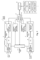
- Fig. 1 shows the structure of the main parts of a radar device 1 according to this invention, provided with a control part 2, a transmission part 3, a reception part 4, a scanning part 5, a horizontal scan position detecting part 6, a vertical scan position detecting part 7 and an external interface (I/F) 8.
- This radar device 1 is adapted to be mounted to a mobile vehicle and its control part 2 is for controlling the operations of each component of the main body, having a memory 2a for storing programs for carrying out the object detecting process to be described in detail below and parameters to be used at the time of its operation.
- the scanning part 5 serves to shift the light projecting lens 3a horizontally and vertically with respect to the light emitting surface of the laser diode 3a.
- the direction of the laser light emitted from the laser diode 3a changes horizontally according to the horizontal shift of the light projecting lens 3c and vertically according to the vertical shift of the light projecting lens 3c.
- the horizontal scan by the laser light from the laser diode 3a is carried out by the horizontal motion of the light projecting lens 3c.
- the vertical scan by the laser light from the laser diode 3 a is carried out by the vertical motion of the light projecting lens 3c. Since the light receiving lens 4c is connected to the light projecting lens 3c, as shown in Fig.
- the scanning part 5 is adapted not only to move the light projecting lens 3c and the light receiving lens 4c as described above and as shown in Fig. 2 but also to move them in the direction perpendicular to the sheet of Fig. 2 .
- so-called Fresnel lenses are shown in Fig. 2 , lenses with a uniform curvature may be used as long as a sufficient scan range can be obtained.
- the horizontal scan position detecting part 6 obtains from the scanning part 5 the horizontal position of the light projecting lens 3c and transmits it to the control part 2.
- the vertical scan position detecting part 7 obtains from the scanning part 5 the vertical position of the light projecting lens 3c and transmits it to the control part 2.
- the control part 2 calculates the horizontal direction of emission of the laser light from the laser diode 3a based on the horizontal position of the light projecting lens 3c obtained from the horizontal scan position detecting part 6.
- the control part 2 calculates the vertical direction of emission of the laser light from the laser diode 3a based on the vertical position of the light projecting lens 3c obtained from the vertical scan position detecting part 7.
- the external interface (I/F) 8 controls inputs and outputs with the control unit on the side of the vehicle to which the radar device is mounted (hereinafter referred to as the vehicle control unit).
- a GPS device, a navigation device, a yaw rate sensor, a vehicle speed sensor, etc. are connected to the vehicle control unit.
- the radar device 1 reports the position of the detected object, etc. to the vehicle control unit through this external interface 8.
- the radar device 1 also receives information such as the position of the vehicle, map data, the angular speed of the vehicle, and the traveling speed of the vehicle from the vehicle control unit through the external interface 8.
- the yaw rate sensor may be provided on the side of the radar device 1.
- the memory 2a stores a program for carrying out this detection process, and information such as the travel speed of the vehicle is inputted from the side of the vehicle to the control part 2 through the external interface 8.
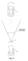
- Figs. 3 and 4 are drawings for explaining this process.
- a detector head incorporating the laser diode 3a, the light projecting lens 3c, the photodiode 4a, the light receiving lens 4c and the scanning part 5 is affixed to a front surface part of the own vehicle 10.
- Numeral 11 indicates another vehicle (hereinafter referred to as the front-going vehicle) traveling in front of the own vehicle 10.
- the radar device 1 moves the laser light emitted from the laser diode 3a horizontally. Explained more in detail, this is done by the scanning part 5 causing the light projecting lens 3c horizontally. This horizontal scan range determines the range of detection for objects.
- the radar device 1 also moves the laser light emitted from the laser diode 3a vertically within a vertical scan range shown in Fig. 4 .
- the control part 2 detects the horizontal and vertical directions of the laser light emitted from the laser diode 3 a based on the horizontal and vertical positions of the light projecting lens 3c inputted from the horizontal scan position detecting part 6 and the vertical scan position detecting part 7.
- the scanning part 5 also moves the light receiving lens 4c in synchronism with the light projecting lens 3c and collects the reflected light from an object on the light receiving surface of the photodiode 4a.
- the light emission controller 3b controls the laser diode 3 a according to a command from the control part 2 so as to transmit laser light at predetermined time intervals, as shown in Fig. 5 .
- the reception circuit 4b processes the output signals from the photodiode 4a such that an electric signal corresponding to the level of the quantity of received light by the photodiode 4a is inputted to the control part 2.
- the quantity of light received by the photodiode 4a increases when the reflected light of the laser light from the laser diode 3a is received, as shown in Fig. 5 .
- the control part 2 calculates the distance L to the object that reflected the laser light emitted from the laser diode 3a from the length of time from the initial time T1 (or T3) when the laser diode 3a emitted light and the final time T2 (or T4) when the photodiode 4a received the reflected light of the laser light emitted from the laser diode 3 a.
- the control part 2 also obtains the direction of the object with respect to the own vehicle 10 by using the horizontal and vertical directions of the emitted laser light obtained from the horizontal scan position detecting part 6 and the vertical scan position detecting part 7. On the basis of the distance and direction of the object, the relative position of the object with respect to the own vehicle 10 is obtained. The position of each object that is detected is communicated to the vehicle control unit through the external interface 8.
- the vehicle control unit carries out the traffic control by following the front going vehicle 11 based on the communication from the radar device 1.
- the radar device 1 determines a direction in which the presence of an object is desired to be detected quickly. This direction will be hereinafter referred to as the standard scan direction.
- the frontal direction is the standard scan direction since it is important to detect the presence of a front going vehicle as quickly as possible.
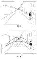
- Fig. 6 is a view taken forward from a vehicle traveling on a straight one-way street with a single lane. Since the laser light emitted from the laser diode 3 a expands in proportion to the distance, the angle of its spread must be limited in order to maintain the energy density high such that the front going vehicle 11 can be kept within the detectable distance. On the other hand, as the spread angle of the laser light increases in the horizontal direction (or as the direction for detecting a pedestrian 12 moves away horizontally from the frontal direction), the range for the pedestrian 12 or objects to be detected moves from the road to the pavement and comes closer to the own vehicle 10, as shown in Fig. 7A .
- the scanning angle of the laser light becomes large in the horizontal direction, the distance between the pedestrian 12 or an object to be detected and the own vehicle 10 becomes substantially shorter. Since the laser light spreads as the distance increases, as explained above, if the laser light is moved horizontally in a scanning motion while its spread is limited, the laser beam becomes too small in the vertical direction at the position of the pedestrian 12 on the pavement near the own vehicle 10, as shown in Figs. 7B and 8 . Thus, at such position corresponding to the pedestrian 12 on the pavement near the own vehicle, the laser light may fail to fall upon the pedestrian 12 or even if the laser light falls upon the pedestrian 12, the reflectivity is very low at such a position or the reflected waves may fail to return to the radar device 1 although the reflectivity may not be too low. In other words, the ability to detect such a pedestrian 12 may be significantly lowered.
- the vertical range of the laser light is approximately the same within the range where the distance to the own vehicle 10 becomes shorter and the pedestrian 12 and objects to be detected exist.
- This radar device 1 is adapted to carry out a detection process while maintaining the detectable distance in the standard scan direction and also maintaining the ability of detection even for objects that are relatively close at positions farther separated from the standard scan direction.
- the vertical range of the laser light irradiation is made approximately equal for each scan angle in the horizontal direction within the range of distance of objects to be detected, as shown in Fig. 10 .
- the detection range is divided into eleven partitions 100-110, and the vertical scan range is changed for each of these partitions according to the range of distance to the target object to be detected.
- Fig. 11 the vertical scan range is changed for each of these partitions according to the range of distance to the target object to be detected.
- the standard scan direction is determined to be the direction of the partition 105, and the vertical scan range of the laser light is made larger as the partition is farther away from the standard scan direction.
- ⁇ 1 be the vertical scan range for the detection partition 105
- ⁇ 2 be that for the detection partitions 104 and 106
- ⁇ 3 be that of the detection partitions 103 and 107
- ⁇ 4 be that of the detection partitions 102 and 108
- ⁇ 5 be that of the detection partitions 101 and 109
- ⁇ 6 be that of the detection partitions 100 and 110 such that ⁇ 1 ⁇ ⁇ 2 ⁇ ⁇ 3 ⁇ ⁇ 4 ⁇ ⁇ S ⁇ ⁇ 6.
- Angles ⁇ 1 - ⁇ 6 are set further such that the vertical length where the laser light is irradiated will be about the same in each of the partitions 100-110 within the range of the distance of the objects to be detected.
- the radar device 1 can not only maintain the detectable distance for objects that exist in the standard scan direction but also maintain the ability to detect objects that are at positions diagonally in front away from the standard scan direction. In other words, it can sufficiently contribute to the traffic safety of the own vehicle 10 to which it is mounted.
- angles ⁇ 1 - ⁇ 6 may be set such that the vertical length where the laser light is irradiated will increase as the separation from the standard scan direction increases.
- the vertical scan ranges may not be asymmetric with respect to the standard scan direction. If the left-hand side of the own vehicle is a pavement and the right-hand side is a traffic lane for the opposite direction, for example, the angle of spread in the vertical direction may be increased gradually on the left-hand side of the standard scan direction such that the detection ability for short distances will be improved while the angle of spread in the vertical direction is not increased on the right-hand side of the standard scan direction such that vehicles moving in the opposite direction can be detected quickly.
- the road condition such as the number of traffic lanes can be obtained through the external interface 8 from the GPS device and the navigation device.
- An upper limit for the scan range in the vertical direction may be set.
- the standard scan direction may be selected according to the travel condition of the own vehicle or the road condition where the own vehicle is traveling.
- the direction of the detected front going vehicle may be selected as the standard scan direction and the vertical scan range may be made larger as one moves farther away from this standard scan direction.
- the radar device 1 is capable of obtaining the position of the own vehicle and the shape of the road ahead from the GPS device and the navigation device through the external interface 8. Similarly, the shape of the road currently being traveled can be obtained by using the yaw rate sensor. The standard scan direction may be determined according to the road condition thus obtained and objects may be detected.
- the shape of the light projecting lens 34c may be designed as shown in Figs, 13-15 such that the spread angle of the laser light in the vertical direction increases stepwise as the position of incidence of the laser light moves away from the center of the light projecting lens 3c in the horizontal direction.
- Fig. 13 shows the situation where the direction of emission of the laser light is approximately to front
- Fig. 14 shows the situation where it is diagonal to the left
- Fig. 15 shows the situation where it is diagonal to the right.
- Figs. 13A , 14A and 15A show the laser light irradiation in the horizontal direction
- Figs. 13B , 14B and 15B show the laser light irradiation in the vertical direction.
- the spread angle of the laser light in the vertical direction increases stepwise due to the horizontal motion of the light projecting lens 3c as the direction of emission of the laser light moves away from the front in the horizontal direction. Since the shape of the light projecting lens 3c is such that the vertical range of laser light irradiation is approximately the same within the range of distance to the object to be detected within each of the partitions 100-110 shown in Fig. 11 , the radar device 1 can secure a detectable distance for objects in the standard scan direction by moving the light projecting lens 3c horizontally when the frontal direction is selected as the standard scan direction and also the ability to detect objects away from the standard scan direction. Thus, the radar device 1 can sufficiently contribute to the safe traffic by the own vehicle 10 to which it is mounted. Moreover, since the structure for causing the radar device 1 to carry out a vertical scan can be dispensed with, the invention contributes to reduction in the size and the cost of the device.
- the vertical range irradiated by the laser light cannot be made equal within the range of distance of objects to be detected within the partitions 100-110 merely by moving the light projecting lens 3c horizontally. If the structure is modified such that the laser light can be operated for a vertical scan, however, the vertical range irradiated by the laser light can be approximately equal within the range of distance of objects to be detected within the partitions 100-110 even if the standard scan direction is determined to be other than the frontal direction.
- the light projecting lens 3c is moved for carrying out the scan by the laser light emitted from the laser diode 3a but the scan may be designed to be carried out by using an electro-optical element (E/O).
- Fig. 16 shows the structure of a main part of another radar device using an electro-optical element, using the same numerals for indicating the like components already described with reference to Fig. 1 .
- this radar device 1 includes an electric field controlling part 22 for applying an electric field onto an electro-optical element 21, instead of the scanning part 5 of Fig. 1 .
- Fig. 16 shows the structure of a main part of another radar device using an electro-optical element, using the same numerals for indicating the like components already described with reference to Fig. 1 .
- this radar device 1 includes an electric field controlling part 22 for applying an electric field onto an electro-optical element 21, instead of the scanning part 5 of Fig. 1 .
- the electro-optical element 21 is disposed in front of the light projecting lens 3c such that the laser light emitted from the laser diode 3 a irradiates the detection area by passing through the light projecting lens 3c and the electro-optical element 21.
- the electro-optical element 21 has the property of changing its index of refraction according to the intensity of electric field to which it is subjected.
- an electro-optical element 21a for changing the index of refraction in the horizontal direction and another electro-optical element 21b for changing the index of refraction in the vertical direction are placed next to each other and the laser light emitted from the laser diode 3a can be moved both horizontally and vertically for scanning.
- the electric field controlling part 22 serves to individually control the electric fields applied to the two electro-optical elements 21a and 21b, that is, to move the laser light horizontally by varying the electric field applied to the electro-optical element 21a and vertically by varying the electric field applied to the electro-optical element 21b.
- the horizontal scan position detecting part 6 detects the horizontal direction of the laser light emission from the intensity of the electric field applied by the electric field controlling part 22 to the electro-optical element 21a
- the vertical scan position detecting part 7 detects the vertical direction of the laser light emission from the intensity of the electric field applied by the electric field controlling part 22 to the electro-optical element 21b.
- the radar device 1 structured as shown in Fig. 16 can move the laser light emitted from the laser diode 3a horizontally and vertically for scanning.
- the detectable distance for objects in the standard scan direction can be secured and the ability to detect objects away from the standard scan direction can also be secured.
- the standard scan direction may be determined based on the travel condition of the own vehicle or the shape of the road on which it is traveling.
- Fig. 17 shows an example with two electro-optical elements
- Fig. 18 shows another example not using the electro-optical element 21b for moving the laser light vertically but forming the laser-projecting surface of the electro-optical element 21a in such a shape as shown in Figs. 18A-18D that the spread angle of the laser light in the vertical direction becomes stepwise larger as the laser light-emitting position becomes farther away horizontally from the center of the light projecting lens 3c.
- Fig. 18A is the plan view of the electro-optical element 21a
- Figs. 18B-18D are respectively a sectional view taken along lines 18B-18B, 18C-18C and 18D-18D.
- the radar device 1 structured as described above can secure the detectable distance for objects in the standard scan direction when the standard scan direction is selected to be the forward direction, and the ability to detect objects away from the standard scan direction can also be secured.
- the electric field controlling part 22 can be without a structure for controlling the electric field to be applied thereto such that the device can be made more compact and the production cost can be reduced.
- the laser-projecting surface of the electro-optical element 21a may be formed as a structure with an optical component having a microlens array, as a structure having a convex surface to converge light first and then to diffuse it, or as a non-spherical surface.
- detecting the direction of emitted laser light based on the intensity of applied electric field to the electro-optical element 21a may be done, as shown in Fig. 19 , by means of a structure having a half mirror 25 and a light position detector (PSD) 26.
- the half mirror 25 is disposed in front of the electro-optical element 21.
- the light position sensor 26 has a plurality of light-receiving elements arranged in the horizontal direction and is disposed at a position where the laser light reflected by the half mirror would be received by one of these light-receiving elements.
- the horizontal scan position detecting part 6 detects the direction of emission of the laser light based on which of the light-receiving elements has received the laser light.
- half mirrors may be placed only at the right-hand and left-hand end portions of the range of the horizontal scan.
- the intensity of the electric field applied to the electro-optical element 21a is detected only when the laser light reached either of the end portions and the relationship between the intensity of the electric field applied to the electro-optical element 21a and the direction of laser light emission is adjusted. This adjustment may be carried out when the main body of the device is started up or after a specified length of time has elapsed. This serves to control the effects of the changes in environmental conditions and the deterioration in the accuracy of detection with time.
- the intensity of applied electric field on the electro-optical element and the change in the index of its refraction are proportional to each other.
- the relationship between the intensity of the applied electric field and the intermediate direction of laser light emission can be adjusted by detecting the intensity of the applied electric field when the laser light has reached the right-hand and left-hand ends.
- half mirrors 25 are placed only at the right-hand and left-hand end portions, since this means that there is no half mirror in the center portion, the loss of the laser light is reduced and the detectable length of objects is not adversely affected.
- light-receiving elements may also be disposed for detecting laser light reflected by these half mirrors 25.
- laser light may be irradiated on these half mirrors 25 at the start-up time or after a specified length of time has elapsed for correcting the relationship between the intensity of electric field applied to the electro-optical element 21a and the direction of emission of the laser light.
- light-receiving elements for directly receiving the laser light may be also disposed at the right-hand and left-hand end portions outside the range of the horizontal scan.
- Fig. 20A shows still another structure with a plurality of electro-optical elements 21 stacked one on top of another vertically such that electric fields can be applied individually thereto and the diameter of the laser beam in the vertical direction can be varied.
- a light guide 30 is used to distribute laser light from a single source into each of the electro-optical elements 21 such that there will be no time delay among the electro-optical elements 21.
- Fig. 20B shows three independent beams by three arrows, since each beam has an extension in the vertical direction, they propagate seemingly as a single beam of light.
- the light guide 30 may be designed such that the emitted laser light will have some spread.
- Fig. 20C shows a situation where each of the electro-optical elements 21 experiences a different electric field, the upper ones experiencing stronger intensity such that the diameter of the beam being projected out keeps increasing as it propagates.
- a polygonal mirror may be used instead for horizontally moving the laser light from a cylindrical lens.
- Use may also be made of a cylindrical lens such that the angle of vertical spread of the incident laser light is the smallest at the center in the horizontal direction, becoming larger as the horizontal distance increases from the center. If the cylindrical lens is made movable in the horizontal direction, the range of laser light irradiation in the vertical direction can be made approximately of the same size within the range of distance for detecting objects even if the standard scan direction is selected to be way from the forward direction.
Landscapes
- Physics & Mathematics (AREA)
- Engineering & Computer Science (AREA)
- General Physics & Mathematics (AREA)
- Computer Networks & Wireless Communication (AREA)
- Radar, Positioning & Navigation (AREA)
- Remote Sensing (AREA)
- Optics & Photonics (AREA)
- Electromagnetism (AREA)
- Optical Radar Systems And Details Thereof (AREA)
- Traffic Control Systems (AREA)
- Measurement Of Optical Distance (AREA)
- Radar Systems Or Details Thereof (AREA)
Abstract
Description
- This invention relates to an object detector which uses electromagnetic waves such as laser light as detecting waves to detect the position of an object.
- Radar devices that are mounted to an automobile and use electromagnetic waves such as laser light as detecting waves to detect the position of an object in front for the purpose of traffic safety have been known. Such a device is adapted to measure the length of time that it takes from the moment the detecting waves are transmitted until reflected waves are received and to obtain the distance to the object that reflected the detecting waves from the measured length of time. The direction to the object that reflected the detecting waves can also be obtained from the direction in which the detecting waves were transmitted at that moment. The radar device repeats this process of obtaining the distance and the direction of an object while varying the horizontal direction of detecting waves within a predetermined range of detection and obtains the relative position of each object inside this range of detection. The radar detector also detects the changes in the distance and the direction of each detected object with the change in time. It can determine whether the object is stationary or moving by calculating the speed of motion of the object by using the speed and the direction of motion of the vehicle to which it is mounted (hereinafter referred to as the own vehicle). A traffic control is carried out on the side of the vehicle if it is determined from the result of detection by the radar device that the detected object is a vehicle traveling in front of the own vehicle.
- Japanese Patent Publication
Tokkai 2000-75030 Tokkai 11-72554 Tokkai 2000-75030 - (a) It is preferable from the point of view of traffic safety to quickly detect an object in front when the own vehicle is traveling fast although the ability to detect objects diagonally in front may be adversely affected; and
- (b) It is preferable from the point of view of traffic safety to improve the ability to detect objects diagonally in front when the own vehicle is traveling relatively slow rather than the ability to detect an object in front quickly.
- A radar device with two axes adapted to move the detecting waves both in horizontal and vertical directions has also been proposed, say, in Japanese Patent Publication
Tokkai 2004-125739 - The purpose of mounting a radar device to a vehicle is to improve traffic safety. Thus, it is not desirable to adversely affect its ability to detect objects diagonally in front when the own vehicle is traveling fast or the ability to quickly detect an object in front when the own vehicle is traveling relatively slowly. In other words, it is important to reduce the negative effects on the ability to detect independent of the speed of travel of the own vehicle.
- It is therefore an object of this invention to provide an object detector capable of maintaining its detection ability both for objects in front and objects diagonally in front.
- An object detector according to this invention is structured as follows in view of this object of the invention.
- A projecting part projects electromagnetic waves such as laser light as detecting waves. A scanning part moves the detecting waves projected by the projecting part in the horizontal direction. A receiving part receives reflected waves of the detecting waves reflected from an object. The position of this object is detected by a position detecting part from elapsed time from when the detecting waves were projected until the reflected waves were received and the direction of projection determined by the scanning part.
- The direction with a maximum detectable distance for objects is defined as the standard scan direction and may be selected as the forward direction. If the main body of the object detector is mounted to a vehicle and the standard scan direction is to be set according to the shape of the road on which the vehicle is traveling, a device for obtaining the shape of the road being traveled upon is provided. The horizontal standard scan direction for the detecting waves is set by a setting means.
- An adjusting means increases the vertical length irradiated by the detecting waves at positions where the distance from the projecting part is the same as the horizontal distance of the direction of projection of the detecting waves from the standard scan direction increases. In other words, the distance over which the vertical length irradiated by the detecting waves is made shorter as the horizontal distance of the direction of projection of the detecting waves from the standard scan direction increases. This may be done by making the scanning part capable of moving the detecting waves vertically and increasing the vertical range of moving the detecting waves as the horizontal distance of the direction of projection of the detecting waves from the standard scan direction increases. This may also be done by making the angle of vertical spread of the detecting waves as the horizontal distance of the direction of projection of the detecting waves from the standard scan direction. A structure combining these methods may be used.
- According to this invention, therefore, the detectable distance of objects in the standard scan direction can be secured and the ability to detect objects away from the standard scan direction can also be secured.
-
-
Fig. 1 is a block diagram of a radar device according to this invention. -
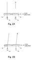
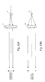
Figs. 2A and 2B , together referred to asFig. 2 , are drawings for explaining the mechanism for moving the laser light. -
Figs. 3 ,4 and 5 are drawings for explaining the process for detecting an object by the radar device. -
Fig. 6 is a view taken forward from a vehicle traveling on a straight one-way street with a single lane. -
Figs. 7A, 7B and 7C , together referred to asFig. 7 , andFigs. 8 - 10 are drawings for explaining the scan range of the laser light in the vertical direction within a range where the presence of an object is to be detected. -
Fig. 11 is a drawing for showing the detection area for objects in the horizontal direction. -
Fig. 12 is a drawing for showing the standard scan direction of a vehicle traveling on a curved road. -
Figs. 13A and 13B , together referred to asFig. 13 ,Figs. 14A and 14B , together referred to asFig. 14 , andFigs. 15A and 15B , together referred to asFig. 15 , are drawings for explaining structures for changing the spread angle of laser light in the horizontal direction by means of the light projecting lens. -
Fig. 16 is a block diagram of another radar device according to this invention. -
Fig. 17 is a drawing for explaining a structure for using electro-optical elements to carry out a scan by laser light. -
Figs. 18A, 18B, 18C and 18D , together referred to asFig. 18 , are drawings for explaining another structure for using an electro-optical element to carry out a scan by laser light. -
Fig. 19 is a drawing for explaining still another structure for using an electro-optical element to carry out a scan by laser light. -
Figs. 20A, 20B and 20C , together referred to asFig. 20 , are drawings for explaining still another structure for using electro-optical elements to carry out a scan by laser light. - The invention is described next by way of embodiments.
-
Fig. 1 shows the structure of the main parts of a radar device 1 according to this invention, provided with acontrol part 2, atransmission part 3, areception part 4, ascanning part 5, a horizontal scanposition detecting part 6, a vertical scanposition detecting part 7 and an external interface (I/F) 8. This radar device 1 is adapted to be mounted to a mobile vehicle and itscontrol part 2 is for controlling the operations of each component of the main body, having amemory 2a for storing programs for carrying out the object detecting process to be described in detail below and parameters to be used at the time of its operation. Thetransmission part 3 includes a laser diode (LD) 3a which is a light emitting element, alight emission controller 3b for controlling the light emission by thelaser diode 3a, and alight projecting lens 3c disposed opposite the light emitting surface of thelaser diode 3a. Thereception part 4 includes a photodiode (PD) 4a which is a light receiving element, areception circuit 4b for processing the output signals of thephotodiode 4a, and a light receivinglens 4c disposed opposite the light receiving surface of thephotodiode 4a. - The scanning
part 5 serves to shift thelight projecting lens 3a horizontally and vertically with respect to the light emitting surface of thelaser diode 3a. The direction of the laser light emitted from thelaser diode 3a changes horizontally according to the horizontal shift of thelight projecting lens 3c and vertically according to the vertical shift of thelight projecting lens 3c. In other words, the horizontal scan by the laser light from thelaser diode 3a is carried out by the horizontal motion of thelight projecting lens 3c. Similarly, the vertical scan by the laser light from thelaser diode 3 a is carried out by the vertical motion of thelight projecting lens 3c. Since thelight receiving lens 4c is connected to thelight projecting lens 3c, as shown inFig. 2 , thelight receiving lens 4c moves horizontally and vertically with respect to the light receiving surface of thephotodiode 4a in synchronism with the movement of thelight projecting lens 3c. Thus, the reflected light of the laser light emitted from thelaser diode 3 a and reflected from an object can be collected on the light receiving surface of thephotodiode 4a. As shown inFig. 2 , as thelight projecting lens 3c is moved to the right, the direction of laser light emitted from thelaser diode 3a tilts to the right-hand direction and as thelight projecting lens 3c is moved to the left, the direction of laser light emitted from thelaser diode 3a tilts to the left-hand direction.Fig. 2A shows a situation where the laser light is emitted approximately in the forward direction.Fig. 2B shows another situation where the direction of emission of the laser light has tilted somewhat to the right-hand direction. - The
scanning part 5 is adapted not only to move thelight projecting lens 3c and thelight receiving lens 4c as described above and as shown inFig. 2 but also to move them in the direction perpendicular to the sheet ofFig. 2 . Although so-called Fresnel lenses are shown inFig. 2 , lenses with a uniform curvature may be used as long as a sufficient scan range can be obtained. - The horizontal scan
position detecting part 6 obtains from thescanning part 5 the horizontal position of thelight projecting lens 3c and transmits it to thecontrol part 2. The vertical scanposition detecting part 7 obtains from thescanning part 5 the vertical position of thelight projecting lens 3c and transmits it to thecontrol part 2. Thecontrol part 2 calculates the horizontal direction of emission of the laser light from thelaser diode 3a based on the horizontal position of thelight projecting lens 3c obtained from the horizontal scanposition detecting part 6. Thecontrol part 2 calculates the vertical direction of emission of the laser light from thelaser diode 3a based on the vertical position of thelight projecting lens 3c obtained from the vertical scanposition detecting part 7. - The external interface (I/F) 8 controls inputs and outputs with the control unit on the side of the vehicle to which the radar device is mounted (hereinafter referred to as the vehicle control unit). A GPS device, a navigation device, a yaw rate sensor, a vehicle speed sensor, etc. are connected to the vehicle control unit. The radar device 1 reports the position of the detected object, etc. to the vehicle control unit through this
external interface 8. The radar device 1 also receives information such as the position of the vehicle, map data, the angular speed of the vehicle, and the traveling speed of the vehicle from the vehicle control unit through theexternal interface 8. For example, the radar device 1 receives the position of the vehicle and the road condition in front from the GPS device and the navigation device and detects the map position of any object from the relative positional relationship between the vehicle and the detected object. Thus, the radar device 1 can also judge whether or not the detected object is on the road being traveled by the vehicle. It is also possible to obtain the radius of curvature of the current travel route of the vehicle from the angular speed of the vehicle obtained from the yaw rate sensor and the traveling speed of the vehicle obtained from the vehicle speed sensor by using the formula:
Thus, the radar device 1 can also determine whether the detected object is on the current travel route of vehicle on the road being traveled upon. The yaw rate sensor may be provided on the side of the radar device 1. - Next, the process of detecting objects by the radar device 1 is explained briefly. The
memory 2a stores a program for carrying out this detection process, and information such as the travel speed of the vehicle is inputted from the side of the vehicle to thecontrol part 2 through theexternal interface 8.Figs. 3 and4 are drawings for explaining this process. A detector head incorporating thelaser diode 3a, thelight projecting lens 3c, thephotodiode 4a, thelight receiving lens 4c and thescanning part 5 is affixed to a front surface part of theown vehicle 10.Numeral 11 indicates another vehicle (hereinafter referred to as the front-going vehicle) traveling in front of theown vehicle 10. Within a horizontal scan range shown inFig. 3 , the radar device 1 moves the laser light emitted from thelaser diode 3a horizontally. Explained more in detail, this is done by thescanning part 5 causing thelight projecting lens 3c horizontally. This horizontal scan range determines the range of detection for objects. The radar device 1 also moves the laser light emitted from thelaser diode 3a vertically within a vertical scan range shown inFig. 4 . Thecontrol part 2 detects the horizontal and vertical directions of the laser light emitted from thelaser diode 3 a based on the horizontal and vertical positions of thelight projecting lens 3c inputted from the horizontal scanposition detecting part 6 and the vertical scanposition detecting part 7. - The
scanning part 5 also moves thelight receiving lens 4c in synchronism with thelight projecting lens 3c and collects the reflected light from an object on the light receiving surface of thephotodiode 4a. Thelight emission controller 3b controls thelaser diode 3 a according to a command from thecontrol part 2 so as to transmit laser light at predetermined time intervals, as shown inFig. 5 . Thereception circuit 4b processes the output signals from thephotodiode 4a such that an electric signal corresponding to the level of the quantity of received light by thephotodiode 4a is inputted to thecontrol part 2. The quantity of light received by thephotodiode 4a increases when the reflected light of the laser light from thelaser diode 3a is received, as shown inFig. 5 . - The
control part 2 calculates the distance L to the object that reflected the laser light emitted from thelaser diode 3a from the length of time from the initial time T1 (or T3) when thelaser diode 3a emitted light and the final time T2 (or T4) when thephotodiode 4a received the reflected light of the laser light emitted from thelaser diode 3 a. The distance L can be calculated as L = c(T2 - T1)/2 where c is the speed of laser light propagation. Thecontrol part 2 also obtains the direction of the object with respect to theown vehicle 10 by using the horizontal and vertical directions of the emitted laser light obtained from the horizontal scanposition detecting part 6 and the vertical scanposition detecting part 7. On the basis of the distance and direction of the object, the relative position of the object with respect to theown vehicle 10 is obtained. The position of each object that is detected is communicated to the vehicle control unit through theexternal interface 8. - The vehicle control unit carries out the traffic control by following the
front going vehicle 11 based on the communication from the radar device 1. - The process for detecting objects by the radar device 1 is explained next more in detail.
- In order to provide sufficient assistance to the traffic safety of the
own vehicle 10, the radar device 1 determines a direction in which the presence of an object is desired to be detected quickly. This direction will be hereinafter referred to as the standard scan direction. When the own vehicle 1 is traveling on a straight road, for example, the frontal direction is the standard scan direction since it is important to detect the presence of a front going vehicle as quickly as possible. -
Fig. 6 is a view taken forward from a vehicle traveling on a straight one-way street with a single lane. Since the laser light emitted from thelaser diode 3 a expands in proportion to the distance, the angle of its spread must be limited in order to maintain the energy density high such that thefront going vehicle 11 can be kept within the detectable distance. On the other hand, as the spread angle of the laser light increases in the horizontal direction (or as the direction for detecting apedestrian 12 moves away horizontally from the frontal direction), the range for thepedestrian 12 or objects to be detected moves from the road to the pavement and comes closer to theown vehicle 10, as shown inFig. 7A . In other words, as the scanning angle of the laser light becomes large in the horizontal direction, the distance between thepedestrian 12 or an object to be detected and theown vehicle 10 becomes substantially shorter. Since the laser light spreads as the distance increases, as explained above, if the laser light is moved horizontally in a scanning motion while its spread is limited, the laser beam becomes too small in the vertical direction at the position of thepedestrian 12 on the pavement near theown vehicle 10, as shown inFigs. 7B and8 . Thus, at such position corresponding to thepedestrian 12 on the pavement near the own vehicle, the laser light may fail to fall upon thepedestrian 12 or even if the laser light falls upon thepedestrian 12, the reflectivity is very low at such a position or the reflected waves may fail to return to the radar device 1 although the reflectivity may not be too low. In other words, the ability to detect such apedestrian 12 may be significantly lowered. - Although it is possible, as shown in
Fig. 9 , to enlarge the spread angle of the laser light such that the diameter of the beam of the laser light in the vertical direction becomes larger at the position of thepedestrian 12 on the pavement near theown vehicle 10, the detectable distance in the standard scan direction becomes shorter, and it becomes not possible to quickly detect an object in the standard scan direction. For this radar device 1, as shown inFig. 7C , the vertical range of the laser light is approximately the same within the range where the distance to theown vehicle 10 becomes shorter and thepedestrian 12 and objects to be detected exist. - This radar device 1 is adapted to carry out a detection process while maintaining the detectable distance in the standard scan direction and also maintaining the ability of detection even for objects that are relatively close at positions farther separated from the standard scan direction. Explained more in detail, the vertical range of the laser light irradiation is made approximately equal for each scan angle in the horizontal direction within the range of distance of objects to be detected, as shown in
Fig. 10 . In the example ofFig. 11 , the detection range is divided into eleven partitions 100-110, and the vertical scan range is changed for each of these partitions according to the range of distance to the target object to be detected. In the example ofFig. 11 , the standard scan direction is determined to be the direction of thepartition 105, and the vertical scan range of the laser light is made larger as the partition is farther away from the standard scan direction. Let θ1 be the vertical scan range for thedetection partition 105, θ2 be that for thedetection partitions detection partitions detection partitions detection partitions detection partitions - Thus, the radar device 1 can not only maintain the detectable distance for objects that exist in the standard scan direction but also maintain the ability to detect objects that are at positions diagonally in front away from the standard scan direction. In other words, it can sufficiently contribute to the traffic safety of the
own vehicle 10 to which it is mounted. - As an alternative example, angles θ1 - θ6 may be set such that the vertical length where the laser light is irradiated will increase as the separation from the standard scan direction increases. As another example, the vertical scan ranges may not be asymmetric with respect to the standard scan direction. If the left-hand side of the own vehicle is a pavement and the right-hand side is a traffic lane for the opposite direction, for example, the angle of spread in the vertical direction may be increased gradually on the left-hand side of the standard scan direction such that the detection ability for short distances will be improved while the angle of spread in the vertical direction is not increased on the right-hand side of the standard scan direction such that vehicles moving in the opposite direction can be detected quickly. The road condition such as the number of traffic lanes can be obtained through the
external interface 8 from the GPS device and the navigation device. - In order to control the reflections from the road surface, it is preferable to reduce the amount by which the scan range in the vertical direction is made wider in the downward direction and to increase the amount by which the scan range in the vertical direction is made wider in the upward direction with respect to the direction of emission of the laser light in the vertical direction in the standard scan direction. An upper limit for the scan range in the vertical direction may be set. For example, the upper limit may be set equal to θ4 such that angles θ1 - θ6 are θ1 < θ2 < θ3 < θ4 = θ5 = θ6.
- Although an example was explained above in which the frontal direction is defined as the standard scan direction in the horizontal direction, the standard scan direction may be selected according to the travel condition of the own vehicle or the road condition where the own vehicle is traveling. When the
own vehicle 10 having the radar device 1 mounted thereto and thedetection head 9 attached to its front surface is traveling on a curved road, as shown inFig. 12 , for example, the direction of the detected front going vehicle may be selected as the standard scan direction and the vertical scan range may be made larger as one moves farther away from this standard scan direction. - The radar device 1 is capable of obtaining the position of the own vehicle and the shape of the road ahead from the GPS device and the navigation device through the
external interface 8. Similarly, the shape of the road currently being traveled can be obtained by using the yaw rate sensor. The standard scan direction may be determined according to the road condition thus obtained and objects may be detected. - Although an embodiment has been described above wherein the vertical scan range of the laser light is changed for each of the partitions 100-110 and the vertical range irradiated by the laser light is made approximately the same within the range of distance in which objects are to be detected in that detection partition, the shape of the light projecting lens 34c may be designed as shown in
Figs, 13-15 such that the spread angle of the laser light in the vertical direction increases stepwise as the position of incidence of the laser light moves away from the center of thelight projecting lens 3c in the horizontal direction.Fig. 13 shows the situation where the direction of emission of the laser light is approximately to front,Fig. 14 shows the situation where it is diagonal to the left andFig. 15 shows the situation where it is diagonal to the right.Figs. 13A ,14A and15A show the laser light irradiation in the horizontal direction andFigs. 13B ,14B and15B show the laser light irradiation in the vertical direction. - The spread angle of the laser light in the vertical direction increases stepwise due to the horizontal motion of the
light projecting lens 3c as the direction of emission of the laser light moves away from the front in the horizontal direction. Since the shape of thelight projecting lens 3c is such that the vertical range of laser light irradiation is approximately the same within the range of distance to the object to be detected within each of the partitions 100-110 shown inFig. 11 , the radar device 1 can secure a detectable distance for objects in the standard scan direction by moving thelight projecting lens 3c horizontally when the frontal direction is selected as the standard scan direction and also the ability to detect objects away from the standard scan direction. Thus, the radar device 1 can sufficiently contribute to the safe traffic by theown vehicle 10 to which it is mounted. Moreover, since the structure for causing the radar device 1 to carry out a vertical scan can be dispensed with, the invention contributes to reduction in the size and the cost of the device. - By the structure described above, if the standard scan direction is not set to the frontal direction, the vertical range irradiated by the laser light cannot be made equal within the range of distance of objects to be detected within the partitions 100-110 merely by moving the
light projecting lens 3c horizontally. If the structure is modified such that the laser light can be operated for a vertical scan, however, the vertical range irradiated by the laser light can be approximately equal within the range of distance of objects to be detected within the partitions 100-110 even if the standard scan direction is determined to be other than the frontal direction. - According to the embodiment described above, the
light projecting lens 3c is moved for carrying out the scan by the laser light emitted from thelaser diode 3a but the scan may be designed to be carried out by using an electro-optical element (E/O).Fig. 16 shows the structure of a main part of another radar device using an electro-optical element, using the same numerals for indicating the like components already described with reference toFig. 1 . As shown, this radar device 1 includes an electricfield controlling part 22 for applying an electric field onto an electro-optical element 21, instead of thescanning part 5 ofFig. 1 . As shown inFig. 17 , the electro-optical element 21 is disposed in front of thelight projecting lens 3c such that the laser light emitted from thelaser diode 3 a irradiates the detection area by passing through thelight projecting lens 3c and the electro-optical element 21. - As is well known, the electro-
optical element 21 has the property of changing its index of refraction according to the intensity of electric field to which it is subjected. In the case ofFig. 17 , an electro-optical element 21a for changing the index of refraction in the horizontal direction and another electro-optical element 21b for changing the index of refraction in the vertical direction are placed next to each other and the laser light emitted from thelaser diode 3a can be moved both horizontally and vertically for scanning. The electricfield controlling part 22 serves to individually control the electric fields applied to the two electro-optical elements optical element 21a and vertically by varying the electric field applied to the electro-optical element 21b. The horizontal scanposition detecting part 6 detects the horizontal direction of the laser light emission from the intensity of the electric field applied by the electricfield controlling part 22 to the electro-optical element 21a, and the vertical scanposition detecting part 7 detects the vertical direction of the laser light emission from the intensity of the electric field applied by the electricfield controlling part 22 to the electro-optical element 21b. - Thus, the radar device 1 structured as shown in
Fig. 16 , too, like that structured as shown inFig. 1 , can move the laser light emitted from thelaser diode 3a horizontally and vertically for scanning. Thus, the detectable distance for objects in the standard scan direction can be secured and the ability to detect objects away from the standard scan direction can also be secured. In the case of this example, too, the standard scan direction may be determined based on the travel condition of the own vehicle or the shape of the road on which it is traveling. - While
Fig. 17 shows an example with two electro-optical elements,Fig. 18 shows another example not using the electro-optical element 21b for moving the laser light vertically but forming the laser-projecting surface of the electro-optical element 21a in such a shape as shown inFigs. 18A-18D that the spread angle of the laser light in the vertical direction becomes stepwise larger as the laser light-emitting position becomes farther away horizontally from the center of thelight projecting lens 3c.Fig. 18A is the plan view of the electro-optical element 21a andFigs. 18B-18D are respectively a sectional view taken alonglines 18B-18B, 18C-18C and 18D-18D. - Thus, the radar device 1 structured as described above, too, like the example wherein the
light projecting lens 3c is shifted in the horizontal direction as explained with reference toFigs. 13-15 , can secure the detectable distance for objects in the standard scan direction when the standard scan direction is selected to be the forward direction, and the ability to detect objects away from the standard scan direction can also be secured. If electro-optical element 21b for moving the laser light vertically is not required, the electricfield controlling part 22 can be without a structure for controlling the electric field to be applied thereto such that the device can be made more compact and the production cost can be reduced. - As another embodiment of this invention, the laser-projecting surface of the electro-
optical element 21a may be formed as a structure with an optical component having a microlens array, as a structure having a convex surface to converge light first and then to diffuse it, or as a non-spherical surface. - Although examples of detecting the direction of emitted laser light based on the intensity of applied electric field to the electro-
optical element 21a have been described above, this may be done, as shown inFig. 19 , by means of a structure having ahalf mirror 25 and a light position detector (PSD) 26. Thehalf mirror 25 is disposed in front of the electro-optical element 21. Thelight position sensor 26 has a plurality of light-receiving elements arranged in the horizontal direction and is disposed at a position where the laser light reflected by the half mirror would be received by one of these light-receiving elements. The horizontal scanposition detecting part 6 detects the direction of emission of the laser light based on which of the light-receiving elements has received the laser light. By this method, since the direction of emission of the laser light can be detected directly, the accuracy in the detection of the position of an object can be improved. - Although an example has been shown above wherein the laser light passes through the
half mirror 25 over the entire range of the horizontal scan, half mirrors may be placed only at the right-hand and left-hand end portions of the range of the horizontal scan. The intensity of the electric field applied to the electro-optical element 21a is detected only when the laser light reached either of the end portions and the relationship between the intensity of the electric field applied to the electro-optical element 21a and the direction of laser light emission is adjusted. This adjustment may be carried out when the main body of the device is started up or after a specified length of time has elapsed. This serves to control the effects of the changes in environmental conditions and the deterioration in the accuracy of detection with time. - As is well known, the intensity of applied electric field on the electro-optical element and the change in the index of its refraction are proportional to each other. Thus, the relationship between the intensity of the applied electric field and the intermediate direction of laser light emission can be adjusted by detecting the intensity of the applied electric field when the laser light has reached the right-hand and left-hand ends.
- If the half mirrors 25 are placed only at the right-hand and left-hand end portions, since this means that there is no half mirror in the center portion, the loss of the laser light is reduced and the detectable length of objects is not adversely affected.
- As a variation, not only half mirrors 25 are disposed at the right-hand and left-hand end portions of the range of the horizontal scan, light-receiving elements may also be disposed for detecting laser light reflected by these half mirrors 25. With such a structure, laser light may be irradiated on these half mirrors 25 at the start-up time or after a specified length of time has elapsed for correcting the relationship between the intensity of electric field applied to the electro-
optical element 21a and the direction of emission of the laser light. In addition, light-receiving elements for directly receiving the laser light may be also disposed at the right-hand and left-hand end portions outside the range of the horizontal scan. - Although explanations have been presented above regarding the horizontal movement of the laser light, similar structures are also possible for the vertical movement of the laser light.
-
Fig. 20A shows still another structure with a plurality of electro-optical elements 21 stacked one on top of another vertically such that electric fields can be applied individually thereto and the diameter of the laser beam in the vertical direction can be varied. In the example ofFig. 20A , alight guide 30 is used to distribute laser light from a single source into each of the electro-optical elements 21 such that there will be no time delay among the electro-optical elements 21. - If the same electric field is applied to all of the electro-
optical elements 21, each of them will experience the same change in the index of refraction and the light entering from thelight guide 30 will be projected all in the same direction, as shown inFig. 20B , without spreading. AlthoughFig. 20B shows three independent beams by three arrows, since each beam has an extension in the vertical direction, they propagate seemingly as a single beam of light. Alternatively, thelight guide 30 may be designed such that the emitted laser light will have some spread. -
Fig. 20C shows a situation where each of the electro-optical elements 21 experiences a different electric field, the upper ones experiencing stronger intensity such that the diameter of the beam being projected out keeps increasing as it propagates. - Although not separately illustrated, a polygonal mirror may be used instead for horizontally moving the laser light from a cylindrical lens. Use may also be made of a cylindrical lens such that the angle of vertical spread of the incident laser light is the smallest at the center in the horizontal direction, becoming larger as the horizontal distance increases from the center. If the cylindrical lens is made movable in the horizontal direction, the range of laser light irradiation in the vertical direction can be made approximately of the same size within the range of distance for detecting objects even if the standard scan direction is selected to be way from the forward direction.
Claims (16)
- An object detector comprising:a projecting part for projecting detecting waves;a scanning part for horizontally moving said detecting waves projected by said projecting part;a receiving part for receiving reflected waves of said detecting waves from an object;a position detecting part for detecting the position of said object from elapsed time from when said detecting waves were projected until said reflected waves were received and the direction of projection by said scanning part;setting means for setting a standard scan direction for a horizontal range of scan; andadjusting means for increasing the vertical length irradiated by said detecting waves at positions where the distance from said projecting part is the same as the horizontal distance of the direction of projection of said detecting waves from said standard scan direction increases.
- The object detector of claim 1 wherein said scanning part moves said detecting waves also vertically; and
wherein said adjusting means is also for increasing the vertical range of movement of said detecting waves as the horizontal distance of the direction of projection of said detecting waves from said standard scan direction increases. - The object detector of claim 1 wherein said adjusting means is also for increasing the vertical angle of spread of said detecting waves as the horizontal distance of the direction of projection of said detecting waves from said standard scan direction increases.
- The object detector of claim 2 wherein said adjusting means is also for increasing the vertical angle of spread of said detecting waves as the horizontal distance of the direction of projection of said detecting waves from said standard scan direction increases.
- The object detector of claim 1 further comprising means for obtaining the shape of a road on which a vehicle to which the main body of said object detector is mounted;
wherein said setting means sets said standard scan direction according to said obtained shape. - The object detector of claim 2 further comprising means for obtaining the shape of a road on which a vehicle to which the main body of said object detector is mounted;
wherein said setting means sets said standard scan direction according to said obtained shape. - The object detector of claim 3 further comprising means for obtaining the shape of a road on which a vehicle to which the main body of said object detector is mounted;
wherein said setting means sets said standard scan direction according to said obtained shape. - The object detector of claim 4 further comprising means for obtaining the shape of a road on which a vehicle to which the main body of said object detector is mounted;
wherein said setting means sets said standard scan direction according to said obtained shape. - The object detector of claim 1 wherein said projecting part projects laser light as said detecting waves; and
wherein said adjusting means uses an electro-optical element to adjust the vertical length irradiated by said detecting waves. - The object detector of claim 2 wherein said projecting part projects laser light as said detecting waves; and
wherein said adjusting means uses an electro-optical element to adjust the vertical length irradiated by said detecting waves. - The object detector of claim 3 wherein said projecting part projects laser light as said detecting waves; and
wherein said adjusting means uses an electro-optical element to adjust the vertical length irradiated by said detecting waves. - The object detector of claim 4 wherein said projecting part projects laser light as said detecting waves; and
wherein said adjusting means uses an electro-optical element to adjust the vertical length irradiated by said detecting waves. - The object detector of claim 5 wherein said projecting part projects laser light as said detecting waves; and
wherein said adjusting means uses an electro-optical element to adjust the vertical length irradiated by said detecting waves. - The object detector of claim 6 wherein said projecting part projects laser light as said detecting waves; and
wherein said adjusting means uses an electro-optical element to adjust the vertical length irradiated by said detecting waves. - The object detector of claim 7 wherein said projecting part projects laser light as said detecting waves; and
wherein said adjusting means uses an electro-optical element to adjust the vertical length irradiated by said detecting waves. - The object detector of claim 8 wherein said projecting part projects laser light as said detecting waves; and
wherein said adjusting means uses an electro-optical element to adjust the vertical length irradiated by said detecting waves.
Applications Claiming Priority (1)
| Application Number | Priority Date | Filing Date | Title |
|---|---|---|---|
| JP2007129981A JP2008286565A (en) | 2007-05-16 | 2007-05-16 | Object detection device |
Publications (1)
| Publication Number | Publication Date |
|---|---|
| EP1995606A1 true EP1995606A1 (en) | 2008-11-26 |
Family
ID=39636893
Family Applications (1)
| Application Number | Title | Priority Date | Filing Date |
|---|---|---|---|
| EP08152393A Withdrawn EP1995606A1 (en) | 2007-05-16 | 2008-03-06 | Object detector |
Country Status (4)
| Country | Link |
|---|---|
| US (1) | US20080285010A1 (en) |
| EP (1) | EP1995606A1 (en) |
| JP (1) | JP2008286565A (en) |
| CN (1) | CN101308214A (en) |
Families Citing this family (40)
| Publication number | Priority date | Publication date | Assignee | Title |
|---|---|---|---|---|
| JP5347800B2 (en) * | 2009-07-27 | 2013-11-20 | ソニー株式会社 | Detection system and detection method |
| JP5634046B2 (en) * | 2009-09-25 | 2014-12-03 | クラリオン株式会社 | Sensor controller, navigation device, and sensor control method |
| US10996073B2 (en) * | 2010-12-02 | 2021-05-04 | Telenav, Inc. | Navigation system with abrupt maneuver monitoring mechanism and method of operation thereof |
| JP5707962B2 (en) * | 2011-01-20 | 2015-04-30 | 株式会社リコー | Obstacle detection device |
| DE102012204441B4 (en) | 2011-03-21 | 2026-07-09 | Denso Corporation | Method and device for detecting the course of a road for vehicles |
| KR101833874B1 (en) * | 2011-07-14 | 2018-03-05 | 현대모비스 주식회사 | Smart Cruise Control System Applying Variable Curvature And Method Thereof |
| CN102323593B (en) * | 2011-08-24 | 2016-05-18 | 北京国科环宇空间技术有限公司 | The system of two-dimensional dynamic target capturing |
| CN102508255A (en) * | 2011-11-03 | 2012-06-20 | 广东好帮手电子科技股份有限公司 | Vehicle-mounted four-wire laser radar system and circuit and method thereof |
| CN102495398B (en) * | 2011-12-27 | 2013-05-08 | 北京智华驭新汽车电子技术开发有限公司 | Method and device for regulating collimation axis of radar |
| JP6115013B2 (en) * | 2012-03-06 | 2017-04-19 | 株式会社リコー | Optical deflection device, laser radar device |
| CN102737477B (en) * | 2012-06-13 | 2013-11-06 | 绍兴电力局 | Control method for approaching-proof laser security scanning alarm of high-rise electrified body of transformer substation |
| US20140055252A1 (en) * | 2012-08-24 | 2014-02-27 | Ford Motor Company | Vehicle with safety projector |
| JP6258626B2 (en) * | 2013-08-05 | 2018-01-10 | シャープ株式会社 | Autonomous mobile device and control method thereof |
| JP6415842B2 (en) * | 2014-04-16 | 2018-10-31 | 日本光電工業株式会社 | Rehabilitation support system |
| JP5962706B2 (en) * | 2014-06-04 | 2016-08-03 | トヨタ自動車株式会社 | Driving assistance device |
| JP2016038211A (en) * | 2014-08-05 | 2016-03-22 | リコー光学株式会社 | Laser radar device |
| US10295671B2 (en) * | 2015-05-07 | 2019-05-21 | GM Global Technology Operations LLC | Array lidar with controllable field of view |
| DE102015210015A1 (en) * | 2015-06-01 | 2016-12-01 | Robert Bosch Gmbh | Method and device for determining the position of a vehicle |
| DE102016002441B3 (en) * | 2016-02-29 | 2017-07-20 | Karlsruher Institut für Technologie | Mechanically robust optical measuring system by means of light transit time and / or reflectivity measurement |
| CN105652279A (en) * | 2016-03-11 | 2016-06-08 | 北京维阿时代科技有限公司 | Real-time spatial positioning system and method and virtual reality device comprising system |
| FR3051560B1 (en) * | 2016-05-19 | 2019-08-23 | Institut Vedecom | OPTICAL TELEMETRY SYSTEM |
| JP6631796B2 (en) * | 2016-05-31 | 2020-01-15 | パナソニックIpマネジメント株式会社 | Moving object detecting device, program and recording medium |
| DE102017102635B4 (en) | 2017-02-10 | 2026-04-16 | Valeo Schalter Und Sensoren Gmbh | Deflection device for an optoelectronic sensor of a motor vehicle with at least two electro-optical deflection units, optoelectronic sensor, driver assistance system, motor vehicle and method |
| DE102017102634A1 (en) | 2017-02-10 | 2018-08-16 | Valeo Schalter Und Sensoren Gmbh | Bending device for an optoelectronic sensor of a motor vehicle comprising an optical element for guiding light beams, optoelectronic sensor, driver assistance system and motor vehicle |
| CN108426601A (en) * | 2017-02-12 | 2018-08-21 | 钱浙滨 | A kind of orbital plane control net node working method and device |
| DE102017105210A1 (en) | 2017-03-13 | 2018-09-13 | Valeo Schalter Und Sensoren Gmbh | Optical radiation device for laser pulses with selective optics |
| DE102017205685B4 (en) | 2017-04-04 | 2026-03-26 | Robert Bosch Gmbh | LiDAR device with a dynamic filter and method |
| DE102017208896A1 (en) | 2017-05-26 | 2018-11-29 | Robert Bosch Gmbh | LIDAR device for scanning a scanning area with minimal space requirement |
| DE102017209941A1 (en) * | 2017-06-13 | 2018-12-13 | Robert Bosch Gmbh | Device for detecting an object in the environment |
| DE102017116597B4 (en) * | 2017-07-24 | 2026-05-21 | Valeo Schalter Und Sensoren Gmbh | Transmitting device for a scanning optical detection system of a vehicle, detection system, driver assistance system, method for controlling a beam direction of an optical transmission signal |
| DE102017221797A1 (en) * | 2017-12-04 | 2019-06-06 | Osram Gmbh | Lidar system for environment detection and method for operating a lidar system |
| DE102017129639A1 (en) * | 2017-12-12 | 2019-06-13 | Bircher Reglomat Ag | 3D sensor system with scene lighting dependent on a solid angle |
| DE102017129641A1 (en) * | 2017-12-12 | 2019-06-13 | Bircher Reglomat Ag | 3D sensor system with a free-form optics |
| CN111308441B (en) * | 2018-12-12 | 2024-06-18 | 宁波舜宇车载光学技术有限公司 | Laser radar transmitting device and assembling method |
| KR102789399B1 (en) * | 2018-12-20 | 2025-04-03 | 호쿠요덴키 가부시키가이샤 | Object detection device |
| DE102019211123B4 (en) * | 2019-07-26 | 2024-03-14 | Robert Bosch Gmbh | Beam scanner device and LIDAR device |
| GB202007631D0 (en) * | 2020-05-21 | 2020-07-08 | Cambridge Mechatronics Ltd | A time-of-flight sensor system |
| DE102023201142A1 (en) * | 2023-02-13 | 2024-08-14 | Continental Autonomous Mobility Germany GmbH | Lidar system with waveguide and element with controllable optical material properties for two-dimensional beam direction change |
| DE102023201144A1 (en) * | 2023-02-13 | 2024-08-14 | Continental Autonomous Mobility Germany GmbH | Lidar system with multiple waveguides for beam direction change via frequency change |
| CN118011426B (en) * | 2024-01-30 | 2024-09-13 | 湛江港(集团)股份有限公司 | Ship close range collision prevention early warning method and system based on laser radar |
Citations (6)
| Publication number | Priority date | Publication date | Assignee | Title |
|---|---|---|---|---|
| EP0510613A1 (en) * | 1991-04-23 | 1992-10-28 | Nec Corporation | Moving body measuring apparatus |
| JPH1172554A (en) | 1997-08-28 | 1999-03-16 | Kanto Denshi Oyo Kaihatsu:Kk | In-vehicle millimeter wave radar device |
| JP2000075030A (en) | 1998-08-27 | 2000-03-14 | Aisin Seiki Co Ltd | Scan type laser radar device |
| US20040065814A1 (en) * | 2002-10-07 | 2004-04-08 | Omron Corporation | Object detecting device and method |
| EP1703299A2 (en) * | 2005-03-15 | 2006-09-20 | Omron Corporation | Object detector for a vehicle |
| EP1835302A2 (en) * | 2006-03-15 | 2007-09-19 | Omron Corporation | Distance measuring devce and laser beam projector therefor |
Family Cites Families (3)
| Publication number | Priority date | Publication date | Assignee | Title |
|---|---|---|---|---|
| JP3832101B2 (en) * | 1998-08-05 | 2006-10-11 | 株式会社デンソー | Distance measuring device |
| JP4244964B2 (en) * | 2005-06-06 | 2009-03-25 | オムロン株式会社 | Ranging device for vehicles |
| JP2007101342A (en) * | 2005-10-04 | 2007-04-19 | Omron Corp | Distance measuring device |
-
2007
- 2007-05-16 JP JP2007129981A patent/JP2008286565A/en active Pending
-
2008
- 2008-02-22 US US12/035,726 patent/US20080285010A1/en not_active Abandoned
- 2008-03-06 EP EP08152393A patent/EP1995606A1/en not_active Withdrawn
- 2008-05-16 CN CNA2008100965413A patent/CN101308214A/en active Pending
Patent Citations (7)
| Publication number | Priority date | Publication date | Assignee | Title |
|---|---|---|---|---|
| EP0510613A1 (en) * | 1991-04-23 | 1992-10-28 | Nec Corporation | Moving body measuring apparatus |
| JPH1172554A (en) | 1997-08-28 | 1999-03-16 | Kanto Denshi Oyo Kaihatsu:Kk | In-vehicle millimeter wave radar device |
| JP2000075030A (en) | 1998-08-27 | 2000-03-14 | Aisin Seiki Co Ltd | Scan type laser radar device |
| US20040065814A1 (en) * | 2002-10-07 | 2004-04-08 | Omron Corporation | Object detecting device and method |
| JP2004125739A (en) | 2002-10-07 | 2004-04-22 | Omron Corp | Object detection apparatus and method |
| EP1703299A2 (en) * | 2005-03-15 | 2006-09-20 | Omron Corporation | Object detector for a vehicle |
| EP1835302A2 (en) * | 2006-03-15 | 2007-09-19 | Omron Corporation | Distance measuring devce and laser beam projector therefor |
Also Published As
| Publication number | Publication date |
|---|---|
| US20080285010A1 (en) | 2008-11-20 |
| JP2008286565A (en) | 2008-11-27 |
| CN101308214A (en) | 2008-11-19 |
Similar Documents
| Publication | Publication Date | Title |
|---|---|---|
| US20080285010A1 (en) | Object detector | |
| EP2631667B1 (en) | Distance measuring device | |
| US11555990B2 (en) | Laser radar | |
| EP4260086B1 (en) | Fiber-based transmitter and receiver channels of light detection and ranging systems | |
| JP2021507207A (en) | Systems and methods for adaptive range coverage using lidar | |
| US20100245799A1 (en) | Distance measuring apparatus | |
| JPH09115093A (en) | Vehicle automatic guidance device and method | |
| CN111033306A (en) | Light detection and ranging (LIDAR) device range aliasing resilience through multiple hypotheses | |
| US20240118389A1 (en) | Curved window for expansion of fov in lidar application | |
| US11624809B2 (en) | Laser radar | |
| JP2023535555A (en) | Dynamic compensation for polygon and motor tolerances using galvo control profiles | |
| EP4323800A1 (en) | Lidar systems and methods for vehicle corner mount | |
| WO2024063880A1 (en) | Low-profile lidar system with single polygon and multiple oscillating mirror scanners | |
| WO2022187170A1 (en) | Fiber-based transmitter and receiver channels of light detection and ranging systems | |
| US20240094351A1 (en) | Low-profile lidar system with single polygon and multiple oscillating mirror scanners | |
| US11768294B2 (en) | Compact lidar systems for vehicle contour fitting | |
| JP2008096112A (en) | Radar equipment | |
| US20240210541A1 (en) | Detector alignment method for lidar production | |
| US20240230848A9 (en) | Two dimensional transmitter array-based lidar | |
| US20240168206A1 (en) | Systems and methods for polygon mirror angles adjustment | |
| US20230366984A1 (en) | Dual emitting co-axial lidar system with zero blind zone | |
| US20230366988A1 (en) | Low profile lidar systems with multiple polygon scanners | |
| WO2024076687A1 (en) | Curved window for expansion of fov in lidar application | |
| KR102435908B1 (en) | Optical system for exposing 2d light sheet and 3d light diffusion | |
| JP2002022830A (en) | Distance measuring device and its distance measuring method |
Legal Events
| Date | Code | Title | Description |
|---|---|---|---|
| PUAI | Public reference made under article 153(3) epc to a published international application that has entered the european phase |
Free format text: ORIGINAL CODE: 0009012 |
|
| AK | Designated contracting states |
Kind code of ref document: A1 Designated state(s): AT BE BG CH CY CZ DE DK EE ES FI FR GB GR HR HU IE IS IT LI LT LU LV MC MT NL NO PL PT RO SE SI SK TR |
|
| AX | Request for extension of the european patent |
Extension state: AL BA MK RS |
|
| 17P | Request for examination filed |
Effective date: 20090320 |
|
| 17Q | First examination report despatched |
Effective date: 20090421 |
|
| AKX | Designation fees paid |
Designated state(s): AT BE BG CH CY CZ DE DK EE ES FI FR GB GR HR HU IE IS IT LI LT LU LV MC MT NL NO PL PT RO SE SI SK TR |
|
| STAA | Information on the status of an ep patent application or granted ep patent |
Free format text: STATUS: THE APPLICATION IS DEEMED TO BE WITHDRAWN |
|
| 18D | Application deemed to be withdrawn |
Effective date: 20090902 |