EP1995524A2 - Hinge for wings or doors - Google Patents
Hinge for wings or doors Download PDFInfo
- Publication number
- EP1995524A2 EP1995524A2 EP08156280A EP08156280A EP1995524A2 EP 1995524 A2 EP1995524 A2 EP 1995524A2 EP 08156280 A EP08156280 A EP 08156280A EP 08156280 A EP08156280 A EP 08156280A EP 1995524 A2 EP1995524 A2 EP 1995524A2
- Authority
- EP
- European Patent Office
- Prior art keywords
- box
- hinge
- hinge according
- shaped body
- door
- Prior art date
- Legal status (The legal status is an assumption and is not a legal conclusion. Google has not performed a legal analysis and makes no representation as to the accuracy of the status listed.)
- Granted
Links
Images


Classifications
-
- E—FIXED CONSTRUCTIONS
- E05—LOCKS; KEYS; WINDOW OR DOOR FITTINGS; SAFES
- E05F—DEVICES FOR MOVING WINGS INTO OPEN OR CLOSED POSITION; CHECKS FOR WINGS; WING FITTINGS NOT OTHERWISE PROVIDED FOR, CONCERNED WITH THE FUNCTIONING OF THE WING
- E05F5/00—Braking devices, e.g. checks; Stops; Buffers
- E05F5/02—Braking devices, e.g. checks; Stops; Buffers specially for preventing the slamming of swinging wings during final closing movement, e.g. jamb stops
-
- E—FIXED CONSTRUCTIONS
- E05—LOCKS; KEYS; WINDOW OR DOOR FITTINGS; SAFES
- E05F—DEVICES FOR MOVING WINGS INTO OPEN OR CLOSED POSITION; CHECKS FOR WINGS; WING FITTINGS NOT OTHERWISE PROVIDED FOR, CONCERNED WITH THE FUNCTIONING OF THE WING
- E05F1/00—Closers or openers for wings, not otherwise provided for in this subclass
- E05F1/08—Closers or openers for wings, not otherwise provided for in this subclass spring-actuated, e.g. for horizontally sliding wings
- E05F1/10—Closers or openers for wings, not otherwise provided for in this subclass spring-actuated, e.g. for horizontally sliding wings for swinging wings, e.g. counterbalance
- E05F1/12—Mechanisms in the shape of hinges or pivots, operated by springs
- E05F1/1246—Mechanisms in the shape of hinges or pivots, operated by springs with a coil spring perpendicular to the pivot axis
- E05F1/1253—Mechanisms in the shape of hinges or pivots, operated by springs with a coil spring perpendicular to the pivot axis with a compression spring
- E05F1/1261—Mechanisms in the shape of hinges or pivots, operated by springs with a coil spring perpendicular to the pivot axis with a compression spring for counterbalancing
-
- F—MECHANICAL ENGINEERING; LIGHTING; HEATING; WEAPONS; BLASTING
- F24—HEATING; RANGES; VENTILATING
- F24C—DOMESTIC STOVES OR RANGES ; DETAILS OF DOMESTIC STOVES OR RANGES, OF GENERAL APPLICATION
- F24C15/00—Details
- F24C15/02—Doors specially adapted for stoves or ranges
- F24C15/023—Mounting of doors, e.g. hinges, counterbalancing
-
- E—FIXED CONSTRUCTIONS
- E05—LOCKS; KEYS; WINDOW OR DOOR FITTINGS; SAFES
- E05Y—INDEXING SCHEME ASSOCIATED WITH SUBCLASSES E05D AND E05F, RELATING TO CONSTRUCTION ELEMENTS, ELECTRIC CONTROL, POWER SUPPLY, POWER SIGNAL OR TRANSMISSION, USER INTERFACES, MOUNTING OR COUPLING, DETAILS, ACCESSORIES, AUXILIARY OPERATIONS NOT OTHERWISE PROVIDED FOR, APPLICATION THEREOF
- E05Y2201/00—Constructional elements; Accessories therefor
- E05Y2201/20—Brakes; Disengaging means; Holders; Stops; Valves; Accessories therefor
- E05Y2201/21—Brakes
-
- E—FIXED CONSTRUCTIONS
- E05—LOCKS; KEYS; WINDOW OR DOOR FITTINGS; SAFES
- E05Y—INDEXING SCHEME ASSOCIATED WITH SUBCLASSES E05D AND E05F, RELATING TO CONSTRUCTION ELEMENTS, ELECTRIC CONTROL, POWER SUPPLY, POWER SIGNAL OR TRANSMISSION, USER INTERFACES, MOUNTING OR COUPLING, DETAILS, ACCESSORIES, AUXILIARY OPERATIONS NOT OTHERWISE PROVIDED FOR, APPLICATION THEREOF
- E05Y2201/00—Constructional elements; Accessories therefor
- E05Y2201/20—Brakes; Disengaging means; Holders; Stops; Valves; Accessories therefor
- E05Y2201/252—Type of friction
- E05Y2201/254—Fluid or viscous friction
- E05Y2201/256—Fluid or viscous friction with pistons or vanes
-
- E—FIXED CONSTRUCTIONS
- E05—LOCKS; KEYS; WINDOW OR DOOR FITTINGS; SAFES
- E05Y—INDEXING SCHEME ASSOCIATED WITH SUBCLASSES E05D AND E05F, RELATING TO CONSTRUCTION ELEMENTS, ELECTRIC CONTROL, POWER SUPPLY, POWER SIGNAL OR TRANSMISSION, USER INTERFACES, MOUNTING OR COUPLING, DETAILS, ACCESSORIES, AUXILIARY OPERATIONS NOT OTHERWISE PROVIDED FOR, APPLICATION THEREOF
- E05Y2201/00—Constructional elements; Accessories therefor
- E05Y2201/20—Brakes; Disengaging means; Holders; Stops; Valves; Accessories therefor
- E05Y2201/262—Type of motion, e.g. braking
- E05Y2201/264—Type of motion, e.g. braking linear
-
- E—FIXED CONSTRUCTIONS
- E05—LOCKS; KEYS; WINDOW OR DOOR FITTINGS; SAFES
- E05Y—INDEXING SCHEME ASSOCIATED WITH SUBCLASSES E05D AND E05F, RELATING TO CONSTRUCTION ELEMENTS, ELECTRIC CONTROL, POWER SUPPLY, POWER SIGNAL OR TRANSMISSION, USER INTERFACES, MOUNTING OR COUPLING, DETAILS, ACCESSORIES, AUXILIARY OPERATIONS NOT OTHERWISE PROVIDED FOR, APPLICATION THEREOF
- E05Y2201/00—Constructional elements; Accessories therefor
- E05Y2201/40—Motors; Magnets; Springs; Weights; Accessories therefor
- E05Y2201/47—Springs
- E05Y2201/474—Compression springs
-
- E—FIXED CONSTRUCTIONS
- E05—LOCKS; KEYS; WINDOW OR DOOR FITTINGS; SAFES
- E05Y—INDEXING SCHEME ASSOCIATED WITH SUBCLASSES E05D AND E05F, RELATING TO CONSTRUCTION ELEMENTS, ELECTRIC CONTROL, POWER SUPPLY, POWER SIGNAL OR TRANSMISSION, USER INTERFACES, MOUNTING OR COUPLING, DETAILS, ACCESSORIES, AUXILIARY OPERATIONS NOT OTHERWISE PROVIDED FOR, APPLICATION THEREOF
- E05Y2201/00—Constructional elements; Accessories therefor
- E05Y2201/60—Suspension or transmission members; Accessories therefor
- E05Y2201/604—Transmission members
-
- E—FIXED CONSTRUCTIONS
- E05—LOCKS; KEYS; WINDOW OR DOOR FITTINGS; SAFES
- E05Y—INDEXING SCHEME ASSOCIATED WITH SUBCLASSES E05D AND E05F, RELATING TO CONSTRUCTION ELEMENTS, ELECTRIC CONTROL, POWER SUPPLY, POWER SIGNAL OR TRANSMISSION, USER INTERFACES, MOUNTING OR COUPLING, DETAILS, ACCESSORIES, AUXILIARY OPERATIONS NOT OTHERWISE PROVIDED FOR, APPLICATION THEREOF
- E05Y2201/00—Constructional elements; Accessories therefor
- E05Y2201/60—Suspension or transmission members; Accessories therefor
- E05Y2201/622—Suspension or transmission members elements
- E05Y2201/624—Arms
- E05Y2201/626—Levers
-
- E—FIXED CONSTRUCTIONS
- E05—LOCKS; KEYS; WINDOW OR DOOR FITTINGS; SAFES
- E05Y—INDEXING SCHEME ASSOCIATED WITH SUBCLASSES E05D AND E05F, RELATING TO CONSTRUCTION ELEMENTS, ELECTRIC CONTROL, POWER SUPPLY, POWER SIGNAL OR TRANSMISSION, USER INTERFACES, MOUNTING OR COUPLING, DETAILS, ACCESSORIES, AUXILIARY OPERATIONS NOT OTHERWISE PROVIDED FOR, APPLICATION THEREOF
- E05Y2900/00—Application of doors, windows, wings or fittings thereof
- E05Y2900/30—Application of doors, windows, wings or fittings thereof for domestic appliances
- E05Y2900/308—Application of doors, windows, wings or fittings thereof for domestic appliances for ovens
Definitions
- the present invention relates to a hinge for wings or doors, and in particular to a hinge designed to connect doors of electrical appliances, such as ovens, to the respective supporting frame.
- Hinges of this type normally consist of two separate parts, kinematically connected to one another, directly or by inserting a lever or the like between them.
- hinges usually comprise two separate elements, kinematically connected to one another and both having a box-shaped structure. More precisely, one of the two box-shaped structures is fixed to the oven frame, at one side of the oven mouth, whilst the other box-shaped structure is fixed to one edge of the door, which in that way is rendered movable with a tilting action relative to the above-mentioned frame.
- a lever element is operatively inserted as a connecting element, the lever element pivoting on one of the two box-shaped structures, usually on the one stably fixed to the door, and having a first arm rigidly connected to the other of the two box-shaped structures.
- the second arm of the lever element coplanar with the first, is operated on by elastic elements which influence the movement of the door, for both opening and closing.
- the elastic elements oppose, during a first step, the detachment of the door from the oven supporting frame and, in a second step, subsequent rotation of the door and its consequent lowering to an end of stroke position in which the oven mouth is completely open.
- the door under the combined action of its own weight which promotes its descent and of the elastic elements which apply a braking action, performs a gradual rotation.
- the action of the elastic elements is first balanced by the weight of the door, initially guaranteeing gradual closing rotation; however, then, in the absence of a suitable braking action by the user, the elastic elements push the door towards the oven frame with such a force that it often closes in a rather sudden and noisy way.
- the present invention has for an aim to provide a hinge for wings or doors which is free of the above-mentioned disadvantage and which at the same time has a simple structure and practical and effective operation.
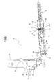
- the numeral 1 denotes as a whole an oven comprising a frame 2 to which a door 3 is connected by two hinges 4, which allow the door to rotate with a tilting action about a horizontal axis A.
- FIGS 2 to 4 illustrate a first embodiment of a hinge 4 made in accordance with the present invention.
- Each of the two hinges 4 comprises a first box-shaped body 5, fixed to the oven 1 frame 2 at a respective side of the oven mouth, and a second box-shaped body 6, fixed to a respective edge of the door 3.
- Both of the box-shaped bodies 5 and 6 have an extended shape and they are kinematically connected to one another by a connecting element 7, which is also part of the hinge 4.
- the connecting element 7 pivots on the second box-shaped body 6 by means of a pin 8 and has a portion 7a rigidly connected to the first body 5 to render the door 3 movable with a tilting action relative to the frame 2 between a closed limit position, illustrated in Figure 4 , and an open limit position, not illustrated.
- illustrations of door 3 and hinge 4 partially open positions are useful, for example the configurations illustrated in Figures 2 and 3 .
- the hinge 4 also comprises a helical spring 9 fitted on the outside of the second box-shaped body 6.
- the lower end coil 9a of the spring 9 is in contact with a transversal wall 10 of the second box-shaped body 6.
- the spring 9 is held in contact with said transversal wall 10 by the head 11 of a bar 12 positioned coaxially inside the spring 9 and which forms a guide for the spring 9.
- One end 12a of the bar 12 exits the bottom of the spring 9 and passes through an opening made in the transversal wall 10 and hooks onto a first longitudinal end 13a of a tension rod 13, whose second longitudinal end 13b is hinged to the connecting element 7 by a pin 14 positioned close to the above-mentioned pin 8.
- the hinge 4 comprises a gas or fluid damper cylinder 15 supported by a respective supporting plate 16 fixed cantilever-style on the first box-shaped body 5.
- the cylinder 15 comprises a fixed rod 17, integral with the plate 16, and a body 18 which can move relative to the rod 17.
- the damper cylinder 15 forms for the hinge 4 respective damping means 19 which, as explained in more detail below, are designed to apply on the second box-shaped body 6 an action damping its movement towards the first box-shaped body 5, as the door 3 passes from an open position to the above-mentioned closed position.
- the hinge 4 also comprises a rocker lever 20, pivoting on the first box-shaped body 5 by means of a relative pin 21, so that it can rotate about its own pivoting axis B, perpendicular to the plane of Figures 2 to 4 .
- the lever 20 On opposite sides of the pin 21, the lever 20 has a first and a second arm, respectively labelled 20a and 20b.
- the first arm 20a of the lever 20 is designed to engage with the damper cylinder 15, to press the movable body 18 against the rod 17.
- the lever 20 forms, for the hinge 4, respective means 22 for operating the damping means 19.
- the second box-shaped body 6 has a projecting peg 23, extending towards the first box-shaped body 5.
- the projecting peg 23 constitutes a control element 24 for the rocker lever 20.
- the element 24 is designed to engage with the second arm 20b of the lever 20 to make the lever rotate about its pivoting axis B.
- the projecting peg 23, integral with the second box-shaped body 6, pushing the second arm 20b of the lever 20, causes the lever 20 to rotate anticlockwise about its pivoting axis B. Said rotation of the lever 20 results in its first arm 20a in turn pushing the movable body 15 against the fixed rod 17, compressing the damper cylinder 15.
- FIGS 5 to 7 illustrate a second embodiment of a hinge 4 made in accordance with the present invention.
- the hinge 4 comprises a rocker lever 20', pivoting on the first box-shaped body 5 by means of a relative pin 21, so that it can rotate about its own pivoting axis B.
- the rocker lever 20' is positioned close to the connecting element 7 between the two box-shaped bodies 5, 6.
- the lever 20' On opposite sides of the pin 21, the lever 20' has a first and a second arm, respectively labelled 20'a and 20'b.
- the first arm 20'a of the lever 20' is designed to engage with the damper cylinder 15, to press the movable body 18 against the rod 17.
- the lever 20' forms, for the hinge 4, respective means 22 for operating the damping means 19.
- control element 24 consists of a wall 25 of the second box-shaped body 6 which is designed to engage, edgeways, with the second arm 20'b of the lever 20.
- FIGS 8 to 10 illustrate a third embodiment of a hinge 4 made in accordance with the present invention.
- the hinge 4 in Figures 8 to 10 differs from the hinge described above and illustrated in Figures 2 to 4 only in the presence of a device 26 for moving the peg 23, the device 26 being designed to move the peg 23 forward and backward depending on the different door 3 closing or opening steps.
- the movement device 26 comprises a slide 27 integral with the tension rod 13.
- the slide 27 comprises a cam profile 28 against which a peg 23 inner head 23a is designed to slidably engage.
- the peg 23 slidably engages in a cylindrical bushing 29, fixed to the second box-shaped body 6, and a helical spring 30 is inserted between the bushing 29 and the head 23a of the peg 23 to apply an elastic force opposing movement of the head 23a towards the bushing 29.
- the peg 23 With the second box-shaped body 6 in the position illustrated in Figure 8 , the peg 23 is in its first, back non-operating configuration. In other words, the peg 23 is practically housed inside the space delimited by the second box-shaped body 6.
- the peg 23 stably adopts its second, forward operating configuration in which, acting as the control element 24, it can engage with and push the rocker lever 20, similarly to what was described above with reference to the hinge 4 illustrated in Figures 2 to 4 .
- damping means 19 are supported by the first box-shaped body 5 and therefore are housed embedded in the electrical appliance frame 2, in a position that is hidden from view and which is protected from knocks or dirt, with obvious advantages in terms of appearance and reliable operation.
- the damping means 19 are also better protected from heat than they would be if they were contained in the door 3.
- control element 24 was described and illustrated as a peg or a wall of the box-shaped body, but it shall be understood that such embodiments are provided by way of example only and are non-limiting, since it could be made in any shape and size.
Landscapes
- Engineering & Computer Science (AREA)
- Chemical & Material Sciences (AREA)
- Combustion & Propulsion (AREA)
- Mechanical Engineering (AREA)
- General Engineering & Computer Science (AREA)
- Closing And Opening Devices For Wings, And Checks For Wings (AREA)
- Hinges (AREA)
- Refrigerator Housings (AREA)
- Wing Frames And Configurations (AREA)
Abstract
Description
- The present invention relates to a hinge for wings or doors, and in particular to a hinge designed to connect doors of electrical appliances, such as ovens, to the respective supporting frame.
- In the following description and by way of example only, without limiting the scope of the invention, the present invention is described with reference to an oven.
- Hinges of this type normally consist of two separate parts, kinematically connected to one another, directly or by inserting a lever or the like between them.
- In known types of ovens hinges usually comprise two separate elements, kinematically connected to one another and both having a box-shaped structure. More precisely, one of the two box-shaped structures is fixed to the oven frame, at one side of the oven mouth, whilst the other box-shaped structure is fixed to one edge of the door, which in that way is rendered movable with a tilting action relative to the above-mentioned frame.
- Between the two box-shaped structures a lever element is operatively inserted as a connecting element, the lever element pivoting on one of the two box-shaped structures, usually on the one stably fixed to the door, and having a first arm rigidly connected to the other of the two box-shaped structures. The second arm of the lever element, coplanar with the first, is operated on by elastic elements which influence the movement of the door, for both opening and closing.
- During door rotation starting from the closed position, the elastic elements oppose, during a first step, the detachment of the door from the oven supporting frame and, in a second step, subsequent rotation of the door and its consequent lowering to an end of stroke position in which the oven mouth is completely open. In this second opening step, the door, under the combined action of its own weight which promotes its descent and of the elastic elements which apply a braking action, performs a gradual rotation.
- During door rotation starting from its open end of stroke position, the action of the elastic elements is first balanced by the weight of the door, initially guaranteeing gradual closing rotation; however, then, in the absence of a suitable braking action by the user, the elastic elements push the door towards the oven frame with such a force that it often closes in a rather sudden and noisy way.
- The present invention has for an aim to provide a hinge for wings or doors which is free of the above-mentioned disadvantage and which at the same time has a simple structure and practical and effective operation.
- The technical features of the present invention, in accordance with the above aim, are clear from the content of the claims herein, in particular claim 1 and, preferably, from any of the claims directly or indirectly dependent on claim 1.
- The advantages of the present invention are more apparent in the detailed description which follows, with reference to the accompanying drawings which illustrate preferred, non-limiting embodiments of the invention, in which:
-
Figure 1 is a schematic perspective top view of an oven fitted with a door which is connected to it by two hinges made in accordance with the present invention; -
Figures 2 to 4 are respective side elevation views with some parts in cross-section and others transparent, of a first embodiment of the hinge for wings or doors in accordance with the present invention, in its three different operating steps; -
Figures 5 to 7 are respective side elevation views with some parts in cross-section and others transparent, of a second embodiment of the hinge for wings or doors in accordance with the present invention, in its three different operating steps; -
Figures 8 to 10 are respective side elevation views with some parts in cross-section and others transparent, of a third embodiment of the hinge for wings or doors in accordance with the present invention, in its three different operating steps. - With reference to
Figure 1 , the numeral 1 denotes as a whole an oven comprising aframe 2 to which a door 3 is connected by twohinges 4, which allow the door to rotate with a tilting action about a horizontal axis A. -
Figures 2 to 4 illustrate a first embodiment of ahinge 4 made in accordance with the present invention. - Each of the two
hinges 4 comprises a first box-shaped body 5, fixed to the oven 1frame 2 at a respective side of the oven mouth, and a second box-shaped body 6, fixed to a respective edge of the door 3. - Both of the box-
shaped bodies element 7, which is also part of thehinge 4. The connectingelement 7 pivots on the second box-shaped body 6 by means of apin 8 and has aportion 7a rigidly connected to thefirst body 5 to render the door 3 movable with a tilting action relative to theframe 2 between a closed limit position, illustrated inFigure 4 , and an open limit position, not illustrated. For a better understanding of the invention, illustrations of door 3 andhinge 4 partially open positions are useful, for example the configurations illustrated inFigures 2 and3 . - The
hinge 4 also comprises ahelical spring 9 fitted on the outside of the second box-shaped body 6. Thelower end coil 9a of thespring 9 is in contact with atransversal wall 10 of the second box-shaped body 6. - The
spring 9 is held in contact with saidtransversal wall 10 by thehead 11 of abar 12 positioned coaxially inside thespring 9 and which forms a guide for thespring 9. - One
end 12a of thebar 12 exits the bottom of thespring 9 and passes through an opening made in thetransversal wall 10 and hooks onto a firstlongitudinal end 13a of atension rod 13, whose secondlongitudinal end 13b is hinged to the connectingelement 7 by apin 14 positioned close to the above-mentionedpin 8. - The position of the
pin 14, where the elastic reaction force of thespring 9 is applied, relative to thepin 8, and the pre-compression of thespring 9, guarantee an elastic action which tends to continuously push and hold the door 3 in its closed position. - As illustrated in
Figures 2 to 4 , thehinge 4 comprises a gas orfluid damper cylinder 15 supported by a respective supportingplate 16 fixed cantilever-style on the first box-shaped body 5. - In the particular, non-limiting embodiment illustrated in
Figures 2 to 4 , thecylinder 15 comprises afixed rod 17, integral with theplate 16, and abody 18 which can move relative to therod 17. - Irrespective of whether it is of the type using gas or fluid, the
damper cylinder 15 forms for thehinge 4 respective damping means 19 which, as explained in more detail below, are designed to apply on the second box-shaped body 6 an action damping its movement towards the first box-shaped body 5, as the door 3 passes from an open position to the above-mentioned closed position. - The
hinge 4 also comprises arocker lever 20, pivoting on the first box-shaped body 5 by means of arelative pin 21, so that it can rotate about its own pivoting axis B, perpendicular to the plane ofFigures 2 to 4 . - On opposite sides of the
pin 21, thelever 20 has a first and a second arm, respectively labelled 20a and 20b. - The
first arm 20a of thelever 20 is designed to engage with thedamper cylinder 15, to press themovable body 18 against therod 17. - The
lever 20 forms, for thehinge 4, respective means 22 for operating the damping means 19. - As illustrated in
Figures 2 to 4 , close to itsupper zone 6a, the second box-shaped body 6 has a projectingpeg 23, extending towards the first box-shaped body 5. - The projecting
peg 23 constitutes acontrol element 24 for the rocker lever 20. As described in more detail below, theelement 24 is designed to engage with thesecond arm 20b of thelever 20 to make the lever rotate about its pivoting axis B. - The following is a brief description of the operation of one of the
hinges 4 illustrated inFigures 2 to 4 , starting from a door 3 open position. - Starting from the door 3 fully open position, not illustrated, a rotation of the door and of the second box-
shaped body 6 about the axis A towards the closed position is promoted by the elastic action of thespring 9 and is initially hindered by the weight of the door 3. - With the second box-
shaped body 6 in the position illustrated inFigure 2 , the elastic reaction force of thespring 9, overcoming the weight, should push the door 3 to close quickly, the door in the meantime having reached a predetermined speed. - Operation of the
spring 9, compressed by the movement of the second box-shaped body 6 due to the pulling action applied by thetension rod 13 and by thebar 12 connected to it, is substantially known and therefore is not described in detail in this text. - As the door 3 closing movement continues, the second box-
shaped body 6 of thehinge 4 reaches the position illustrated inFigure 3 , where theprojecting peg 23 constituting thecontrol element 24 makes contact with thesecond arm 20b of therocker lever 20. - As the door 3 passes between the still partly open position illustrated in
Figure 3 and the closed position shown inFigure 4 , the damping means 19, followingdamper cylinder 15 compression, apply a damping action conflicting with the closing action applied by thespring 9, therefore making door 3 movement towards the fully closed position gradual and subject to a braking action. - In detail, with reference to
Figures 3 and 4 , the projectingpeg 23, integral with the second box-shaped body 6, pushing thesecond arm 20b of thelever 20, causes thelever 20 to rotate anticlockwise about its pivoting axis B. Said rotation of thelever 20 results in itsfirst arm 20a in turn pushing themovable body 15 against thefixed rod 17, compressing thedamper cylinder 15. - It is therefore evident that, even in the absence of a braking action by the user, the door 3, pushed towards the oven 1
frame 2 by thespring 9, reaches the frame in a gentle, silent way thanks to the end of stroke damping provided by the damping means 19. -
Figures 5 to 7 illustrate a second embodiment of ahinge 4 made in accordance with the present invention. - In terms of the structural parts of which the
hinge 4 inFigures 5 to 7 consists, it differs from the hinge described above and illustrated inFigures 2 to 4 only in the different shape of themeans 22 for operating the damping means 19, therelative control element 24 and the different positioning of thedamper cylinder 15. - In detail, with reference to
Figures 5 to 7 , in its second embodiment illustrated, thehinge 4 comprises a rocker lever 20', pivoting on the first box-shaped body 5 by means of arelative pin 21, so that it can rotate about its own pivoting axis B. - In the assembled
hinge 4, the rocker lever 20' is positioned close to the connectingelement 7 between the two box-shaped bodies - On opposite sides of the
pin 21, the lever 20' has a first and a second arm, respectively labelled 20'a and 20'b. - The first arm 20'a of the lever 20' is designed to engage with the
damper cylinder 15, to press themovable body 18 against therod 17. - The lever 20' forms, for the
hinge 4, respective means 22 for operating the damping means 19. - As illustrated in
Figure 5 , thecontrol element 24 consists of awall 25 of the second box-shaped body 6 which is designed to engage, edgeways, with the second arm 20'b of thelever 20. - Similarly to what is described above for the first embodiment of the
hinge 4, hereinafter there is a brief description of operation of thehinge 4 illustrated inFigures 5 to 7 , starting from a door 3 open position. - Starting from the door 3 fully open position, not illustrated, a rotation of the door and of the second box-
shaped body 6 about the axis A towards the closed position is promoted by the elastic action of thespring 9 and is initially hindered by the weight of the door 3. - As the door 3 closing movement continues, the second box-
shaped body 6 of thehinge 4 reaches the position illustrated inFigure 6 , where thewall 25 constituting thecontrol element 24 makes contact with the second arm 20'b of the rocker lever 20'. - As the door 3 passes between the still partly open position illustrated in
Figure 6 and the closed position shown inFigure 7 , the damping means 19, followingdamper cylinder 15 compression, apply a damping action conflicting with the closing action applied by thespring 9, therefore making door 3 movement towards the fully closed position gradual and subject to a braking action. - In detail, with reference to
Figures 6 and 7 , thewall 25 of the second box-shaped body 6, pushing the second arm 20'b of thelever 20, causes thelever 20 to rotate clockwise about its pivoting axis B. Said rotation of the lever 20' results in its first arm 20'a in turn pushing themovable body 15 against thefixed rod 17, compressing thedamper cylinder 15. - As already indicated relative to the first embodiment of the
hinge 4, again for the second embodiment illustrated inFigures 5 to 7 , it is evident that, even in the absence of a braking action by the user, the door 3, pushed by thespring 9 towards the oven 1frame 2, reaches the frame in a gentle, silent way thanks to the end of stroke damping provided by the damping means 19. -
Figures 8 to 10 illustrate a third embodiment of ahinge 4 made in accordance with the present invention. - In terms of the structural parts of which the
hinge 4 inFigures 8 to 10 consists, it differs from the hinge described above and illustrated inFigures 2 to 4 only in the presence of adevice 26 for moving thepeg 23, thedevice 26 being designed to move thepeg 23 forward and backward depending on the different door 3 closing or opening steps. - The
movement device 26 comprises aslide 27 integral with thetension rod 13. Theslide 27 comprises acam profile 28 against which apeg 23inner head 23a is designed to slidably engage. - The
peg 23 slidably engages in acylindrical bushing 29, fixed to the second box-shapedbody 6, and ahelical spring 30 is inserted between thebushing 29 and thehead 23a of thepeg 23 to apply an elastic force opposing movement of thehead 23a towards thebushing 29. - In practice, starting from the door 3 and second box-shaped
body 6 fully open position, illustrated inFigure 8 , a rotation by both about the axis A towards the closed position is promoted by the elastic action of thespring 9 and is initially hindered by the weight of the door 3. - With the second box-shaped
body 6 in the position illustrated inFigure 8 , thepeg 23 is in its first, back non-operating configuration. In other words, thepeg 23 is practically housed inside the space delimited by the second box-shapedbody 6. - As the door 3 closing movement continues, with the rotation of the second box-shaped
body 6 about its axis A, there is a relative movement between thetension rod 13 and the second box-shapedbody 6. Said relative movement causes theslide 27 to slide in the direction indicated by the arrow F inFigure 9 . - The movement of the
slide 27, as a result of contact between theslide 27cam profile 28 and thehead 23a of thepeg 23, causes thepeg 23 to move in the direction of its own axis C, until it exits the second box-shapedbody 6, as illustrated inFigures 9 and 10 . - As illustrated in
Figure 10 , during the door 3 closing step, thepeg 23 stably adopts its second, forward operating configuration in which, acting as thecontrol element 24, it can engage with and push therocker lever 20, similarly to what was described above with reference to thehinge 4 illustrated inFigures 2 to 4 . - In its movement between the first, back configuration and the second, forward configuration, the
peg 23 slides inside thebushing 29 and is opposed by the opposing action of thespring 30. - When the door 3 is opened, that is to say, when passing between the second, forward configuration and the first, back configuration, the
spring 30 pushes thepeg 23 back into the second box-shapedbody 6. - Relative to all three embodiments of the
hinge 4 described above, it must also be emphasised that the damping means 19 are supported by the first box-shapedbody 5 and therefore are housed embedded in theelectrical appliance frame 2, in a position that is hidden from view and which is protected from knocks or dirt, with obvious advantages in terms of appearance and reliable operation. - Moreover, advantageously, thanks to their position in the
frame 2 of the electrical appliance, when this is an oven, the damping means 19 are also better protected from heat than they would be if they were contained in the door 3. - Protection from the heat of the oven allows the life of the damping means 19 to be extended. If they were not protected in this way, their shock absorbing capacity would deteriorate rapidly.
- The
control element 24 was described and illustrated as a peg or a wall of the box-shaped body, but it shall be understood that such embodiments are provided by way of example only and are non-limiting, since it could be made in any shape and size. - According to alternative embodiments of the present invention, not illustrated, there are elements for limiting friction, such as rollers or wheels, inserted between the control element and the rocker lever forming the means for operating the damping means.
Claims (14)
- A hinge for wings or doors, in particular of electrical appliances, comprising:- a first box-shaped body (5) which can be fixed to a frame (2),- a second box-shaped body (6) which can be fixed to a door (3),- connecting means (7) between the box-shaped bodies (5, 6), for rendering the door (3) movable with a tilting action relative to the frame (2) between a closed position and at least one open position, the hinge (4) being characterised in that it comprises damping means (19) supported by the first body (5) for applying on the second body (6) an action damping its movement towards the first body (5), when the closed position is almost reached.
- The hinge according to claim 1, characterised in that the damping means (19) comprise a gas or fluid damper cylinder (15).
- The hinge according to claim 1 or 2, characterised in that it comprises means (22) for operating the damping means (19), said operating means (22) being controlled by the second body (6) when the closed position is almost reached.
- The hinge according to claim 3, characterised in that the operating means (22) comprise a rocker lever (20) pivoting on the first box-shaped body (5) .
- The hinge according to claim 4, characterised in that the second body (6) comprises a control element (24) for the rocker lever (20), the control element (24) being designed to engage with the lever (20), causing the lever to rotate about its own pivoting axis (B).
- The hinge according to claim 5, characterised in that the rocker lever (20) comprises a first arm (20a) designed to engage with the damper cylinder (15), and a second arm (20b) designed to engage with the control element (24).
- The hinge according to claim 5 or 6, characterised in that the control element (24) consists of a peg (23) projecting from the second box-shaped body (6).
- The hinge according to claim 7, characterised in that the peg (23) can move at least between a first, back non-operating configuration and a second, forward operating configuration.
- The hinge according to claim 8, characterised in that it comprises a device (26) for moving the peg (23) between its two configurations, back and forward.
- The hinge according to claim 9, characterised in that the movement device (26) comprises a slide (27) having a cam profile (28) designed to push the peg (23).
- The hinge according to claim 10, characterised in that the movement device (26) comprises a spring (30) opposing the movement of the peg (23).
- The hinge according to claim 5 or 6, characterised in that the control element (24) consists of a wall (25) of the second box-shaped body (6).
- The hinge according to claim 2, characterised in that it comprises a plate (16) for supporting the damper cylinder (15), the plate (16) being fixed cantilever-style on the first box-shaped body (5).
- An electrical appliance comprising at least one hinge (4) according to any of the foregoing claims from 1 to 9.
Priority Applications (1)
| Application Number | Priority Date | Filing Date | Title |
|---|---|---|---|
| PL08156280T PL1995524T3 (en) | 2007-05-23 | 2008-05-15 | Hinge for wings or doors |
Applications Claiming Priority (1)
| Application Number | Priority Date | Filing Date | Title |
|---|---|---|---|
| IT000369A ITBO20070369A1 (en) | 2007-05-23 | 2007-05-23 | HINGE FOR DOORS OR DOORS |
Publications (3)
| Publication Number | Publication Date |
|---|---|
| EP1995524A2 true EP1995524A2 (en) | 2008-11-26 |
| EP1995524A3 EP1995524A3 (en) | 2010-02-24 |
| EP1995524B1 EP1995524B1 (en) | 2013-02-13 |
Family
ID=39535240
Family Applications (1)
| Application Number | Title | Priority Date | Filing Date |
|---|---|---|---|
| EP08156280A Active EP1995524B1 (en) | 2007-05-23 | 2008-05-15 | Hinge for wings or doors |
Country Status (6)
| Country | Link |
|---|---|
| US (1) | US8533914B2 (en) |
| EP (1) | EP1995524B1 (en) |
| CA (1) | CA2631198A1 (en) |
| ES (1) | ES2407464T3 (en) |
| IT (1) | ITBO20070369A1 (en) |
| PL (1) | PL1995524T3 (en) |
Cited By (11)
| Publication number | Priority date | Publication date | Assignee | Title |
|---|---|---|---|---|
| ITMI20091890A1 (en) * | 2009-10-30 | 2011-04-30 | Faringosi Hinges Srl | SMOOTHED HINGE |
| ITTO20090858A1 (en) * | 2009-11-10 | 2011-05-11 | Okey S R L | HIDDEN HINGE FOR WINDOWS WITH BRAKING DEVICE |
| EP2562341A2 (en) | 2011-08-26 | 2013-02-27 | Atasan Metal Sanayi Ticaret Limited Sirketi | Damper hinge counter support system for a home appliance |
| EP2284344A3 (en) * | 2009-07-30 | 2013-07-03 | NUOVA STAR S.p.A. | Improved hinge for wings or doors |
| CN104612513A (en) * | 2015-02-06 | 2015-05-13 | 广东美的厨房电器制造有限公司 | Hinge with buffering effect and device with the same |
| ITBO20130663A1 (en) * | 2013-11-29 | 2015-05-30 | Nuova Star Spa | HINGE FOR HOUSEHOLD APPLIANCES. |
| IT201600088717A1 (en) * | 2016-08-31 | 2018-03-03 | C M I Cerniere Mecc Industriali Srl | HINGE DEVICE WITH DAMPING OF THE END OF THE LOCKING STROKE |
| WO2019066332A1 (en) | 2017-09-29 | 2019-04-04 | Samsung Electronics Co., Ltd. | Washing machine |
| EP3199735B1 (en) * | 2016-01-29 | 2019-07-03 | Apparatebau Gronbach Srl | Hinge, particularly for a household appliance |
| US11543135B2 (en) * | 2017-02-02 | 2023-01-03 | Mansfield Engineered Components, Inc. | Hinge assembly with slow close and/or slow open characteristics |
| US12546482B2 (en) | 2023-10-17 | 2026-02-10 | Mansfield Engineered Components, LLC | Slow open hinge assembly |
Families Citing this family (29)
| Publication number | Priority date | Publication date | Assignee | Title |
|---|---|---|---|---|
| US20120060822A1 (en) * | 2009-05-14 | 2012-03-15 | Schott Gemtron Corporation | Full-view oven doors having locking mechanisms |
| TR200903812A1 (en) | 2009-05-15 | 2010-12-21 | Vestel Beyaz Eşya Sanayi̇ Ve Ti̇caret Anoni̇m Şi̇rketi̇@ | Drawer mounting hinge |
| US8925542B2 (en) | 2009-07-21 | 2015-01-06 | Mansfield Assemblies Co. | Slow open and/or slow close hinge assembly and hinge system |
| IT1396119B1 (en) * | 2009-09-23 | 2012-11-16 | Nuova Star Spa | COMBINATION OF A HINGE FOR DOORS OR DOORS AND A SHOCK ABSORBER. |
| US8338767B2 (en) * | 2010-02-09 | 2012-12-25 | Whirlpool Corporation | Hinge mechanism for a home appliance providing door motion in a non-circular path |
| AU2011370263A1 (en) * | 2011-06-08 | 2013-05-09 | Faringosi Hinges S.R.L. | Hinges provided with elastic means and dampener |
| US20130319394A1 (en) * | 2012-06-01 | 2013-12-05 | John Adam Yantis | Oven hinge damper cooling system |
| US9121211B1 (en) | 2012-10-31 | 2015-09-01 | Mansfield Engineered Components, Inc. | Soft close hinge assembly |
| US10145157B2 (en) * | 2013-01-31 | 2018-12-04 | Mansfield Engineered Components, Inc. | Breakaway hinge receptacle |
| DE202013008777U1 (en) * | 2013-10-07 | 2015-01-08 | Grass Gmbh & Co. Kg | Hinge for a furniture part and furniture |
| DE102015000407B3 (en) * | 2015-01-13 | 2016-04-21 | Apparatebau Gronbach GmbH | Hinge and stove with such a hinge |
| KR101669360B1 (en) * | 2015-03-16 | 2016-10-25 | 엘지전자 주식회사 | Hinge apparatus and oven with hinge apparatus |
| BR102016011179A2 (en) | 2015-05-18 | 2018-07-17 | Atasan Metal Sanayi Ve Ticaret Limited Sirketi | articulation mechanism |
| KR101729058B1 (en) * | 2016-06-10 | 2017-04-21 | 서원코리아 주식회사 | Door hinge |
| IT201600091383A1 (en) * | 2016-09-09 | 2018-03-09 | Nuova Star Spa | SMOOTHED HINGE. |
| CN110234831B (en) * | 2017-01-24 | 2021-07-23 | 菅常工业株式会社 | Shock absorber assemblies and display cases for refrigeration and/or freezing |
| US10082298B2 (en) | 2017-02-02 | 2018-09-25 | Mansfield Engineered Components, Inc. | Hinge assembly with slow close and optional slow open characteristics |
| US10704311B1 (en) * | 2017-02-06 | 2020-07-07 | Mansfield Engineered Components, Inc. | Appliance lid hinge |
| KR102002244B1 (en) * | 2018-01-12 | 2019-07-19 | 서원코리아 주식회사 | Oven Door Hinge |
| KR102040222B1 (en) | 2018-04-16 | 2019-11-04 | 엘지전자 주식회사 | A Latch Module, a Controlling Method thereof and a Cooking Device Using the Same |
| IT201800004849A1 (en) * | 2018-04-24 | 2019-10-24 | HINGE FOR HOUSEHOLD APPLIANCES | |
| PL3853433T3 (en) * | 2018-09-20 | 2023-03-13 | C.M.I. Cerniere Meccaniche Industriali S.R.L. | Damped and compact hinge device |
| US11906170B2 (en) | 2019-04-29 | 2024-02-20 | Winston Industries, Llc | Magnetic positioning hinge for horizontal door assembly |
| CN110259307A (en) * | 2019-05-30 | 2019-09-20 | 江苏星徽精密科技有限公司 | A kind of oven hinge with friction balance mechanism |
| US11414907B2 (en) * | 2019-07-01 | 2022-08-16 | Gulfstream Aerospace Corporation | Door assembly and method for making the same, and aircraft including a door assembly |
| US11377890B1 (en) * | 2020-12-31 | 2022-07-05 | Whirlpool Corporation | Appliance door hinge assembly |
| IT202100002864A1 (en) * | 2021-02-10 | 2022-08-10 | C M I Cerniere Mecc Industriali Srl | HINGE DEVICE WITH DAMPER ACTIVATED BY AN OSCILLATING ELEMENT |
| IT202100025982A1 (en) * | 2021-10-11 | 2023-04-11 | Effegi Brevetti Srl | LIFTING DOOR OPENING DEVICE |
| IT202200026145A1 (en) * | 2022-12-20 | 2024-06-20 | Nuova Star Spa | HINGE FOR DOORS |
Citations (5)
| Publication number | Priority date | Publication date | Assignee | Title |
|---|---|---|---|---|
| DE4100877A1 (en) | 1991-01-14 | 1992-07-16 | Bosch Siemens Hausgeraete | DOOR HINGE FOR FRONT-LOADED HOUSEHOLD APPLIANCES |
| EP0748987A1 (en) | 1995-06-15 | 1996-12-18 | FARINGOSI HINGES S.r.l. | Doors hinge for electric household appliances, furniture or the like, with multiple counterbalancing means |
| DE19901435A1 (en) | 1999-01-18 | 2000-08-03 | Schimmel Pianofortefab | Appliance or furniture has flap closing interior, and dampened by cylinder, piston, piston rod with connecting rod mechanism with two armed lever on bearing |
| EP1217159A2 (en) | 2000-12-19 | 2002-06-26 | bulthaup GmbH & Co. Küchensysteme | Hinge |
| CN2665320Y (en) | 2003-12-05 | 2004-12-22 | 唐桂祥 | Hinge of gas-liquid piston cylinder |
Family Cites Families (29)
| Publication number | Priority date | Publication date | Assignee | Title |
|---|---|---|---|---|
| DE6923018U (en) * | 1969-06-10 | 1970-01-22 | Kunststoff Gmbh | FURNITURE WITH HINGE AND CLAMPING DEVICE |
| US3712287A (en) * | 1970-09-23 | 1973-01-23 | United Filtration Corp | Door hinge |
| FR2163931A5 (en) | 1971-12-07 | 1973-07-27 | France Etat | |
| US3955865A (en) * | 1974-11-04 | 1976-05-11 | General Electric Company | Oven door counterbalance system |
| DE3018184A1 (en) * | 1980-05-13 | 1981-11-19 | Karl Lautenschläger KG, Möbelbeschlagfabrik, 6107 Reinheim | SNAP HINGE |
| DE3039327C2 (en) * | 1980-10-17 | 1988-03-03 | Arturo Salice S.P.A., Novedrate, Como | Hinge joint |
| US4383347A (en) * | 1981-02-25 | 1983-05-17 | The Boeing Company | Four-bar linkage door hinge |
| DE8318790U1 (en) * | 1982-07-16 | 1984-03-01 | Julius Blum Gesellschaft mbH, 6973 Höchst | HINGE |
| US4817240A (en) * | 1983-06-03 | 1989-04-04 | Ace Manufacturing Co. | Appliance door hinge |
| US5075923A (en) | 1991-01-07 | 1991-12-31 | Richard Taylor | Concealed door positioning mechanism |
| US5269043A (en) * | 1992-07-23 | 1993-12-14 | Yang Ming Hua | Pneumatic hinge |
| US5704569A (en) * | 1995-05-12 | 1998-01-06 | The Boeing Company | Counterbalance mechanism for inwardly and upwardly opening plug-type airplane cargo doors |
| DE19522254C2 (en) | 1995-06-20 | 1998-04-30 | Peter Hoffmann | Pneumatic door buffer to prevent slamming of a rotating or sliding door, flap, drawer or the like |
| US7302112B2 (en) * | 2001-04-11 | 2007-11-27 | Sony Corporation | Contour-emphasizing circuit |
| DE20115250U1 (en) | 2001-07-06 | 2002-11-14 | Lautenschlaeger Mepla Werke | damping device |
| US6789293B2 (en) * | 2001-09-27 | 2004-09-14 | Mansfield Assemblies Co. | Dampened hinge system for appliance door |
| DE10254375C1 (en) * | 2002-04-30 | 2003-11-13 | Zimmer Guenther | Furniture component pivot movement damping arrangement, has pivot joint with damping unit to slow movement of component near end position and hinge lever to engage piston-operating unit when component approaches end position |
| US6684453B2 (en) * | 2002-06-14 | 2004-02-03 | Fu Luong Hi-Tech Co., Ltd. | Hinge assembly capable of damping door movement |
| US6845545B2 (en) * | 2002-09-04 | 2005-01-25 | Samsung Electronics Co., Ltd. | Apparatus to close a door of a refrigerator |
| US7150071B2 (en) * | 2003-03-05 | 2006-12-19 | Mansfield Assemblies Co. | Breakaway hinge system for appliance door |
| DE10333925B4 (en) * | 2003-07-24 | 2007-03-22 | Grass Gmbh | Furniture hinge with automatic opening, especially for furniture doors |
| DE602004007870T2 (en) * | 2004-01-16 | 2008-04-17 | Ming-Jeng Lin | hinge device |
| ITBO20060308A1 (en) * | 2006-04-21 | 2007-10-22 | Nuova Star Spa | HINGE FOR DOORS OR DOORS |
| DE102006036473A1 (en) | 2006-08-04 | 2008-02-14 | Suspa Holding Gmbh | Hinge arrangement |
| US7748080B2 (en) | 2007-01-17 | 2010-07-06 | Sub-Zero, Inc. | Hinge and closure device for refrigerator |
| AT9711U1 (en) | 2007-01-29 | 2008-02-15 | Blum Gmbh Julius | FURNITURE FITTING, PARTICULAR FURNITURE HARNESS |
| ITBO20070110A1 (en) * | 2007-02-22 | 2008-08-23 | Nuova Star Spa | HINGE FOR DOORS OR DOORS. |
| DE202007004621U1 (en) | 2007-03-29 | 2008-08-07 | Hettich-Oni Gmbh & Co. Kg | Multilink hinge |
| US20110283478A1 (en) | 2010-05-20 | 2011-11-24 | Global Safety Devices, Llc | Dampening device and system |
-
2007
- 2007-05-23 IT IT000369A patent/ITBO20070369A1/en unknown
-
2008
- 2008-05-13 CA CA002631198A patent/CA2631198A1/en not_active Abandoned
- 2008-05-15 PL PL08156280T patent/PL1995524T3/en unknown
- 2008-05-15 ES ES08156280T patent/ES2407464T3/en active Active
- 2008-05-15 EP EP08156280A patent/EP1995524B1/en active Active
- 2008-05-22 US US12/153,658 patent/US8533914B2/en active Active
Patent Citations (5)
| Publication number | Priority date | Publication date | Assignee | Title |
|---|---|---|---|---|
| DE4100877A1 (en) | 1991-01-14 | 1992-07-16 | Bosch Siemens Hausgeraete | DOOR HINGE FOR FRONT-LOADED HOUSEHOLD APPLIANCES |
| EP0748987A1 (en) | 1995-06-15 | 1996-12-18 | FARINGOSI HINGES S.r.l. | Doors hinge for electric household appliances, furniture or the like, with multiple counterbalancing means |
| DE19901435A1 (en) | 1999-01-18 | 2000-08-03 | Schimmel Pianofortefab | Appliance or furniture has flap closing interior, and dampened by cylinder, piston, piston rod with connecting rod mechanism with two armed lever on bearing |
| EP1217159A2 (en) | 2000-12-19 | 2002-06-26 | bulthaup GmbH & Co. Küchensysteme | Hinge |
| CN2665320Y (en) | 2003-12-05 | 2004-12-22 | 唐桂祥 | Hinge of gas-liquid piston cylinder |
Cited By (15)
| Publication number | Priority date | Publication date | Assignee | Title |
|---|---|---|---|---|
| EP2284344A3 (en) * | 2009-07-30 | 2013-07-03 | NUOVA STAR S.p.A. | Improved hinge for wings or doors |
| ITMI20091890A1 (en) * | 2009-10-30 | 2011-04-30 | Faringosi Hinges Srl | SMOOTHED HINGE |
| ITTO20090858A1 (en) * | 2009-11-10 | 2011-05-11 | Okey S R L | HIDDEN HINGE FOR WINDOWS WITH BRAKING DEVICE |
| EP2562341A2 (en) | 2011-08-26 | 2013-02-27 | Atasan Metal Sanayi Ticaret Limited Sirketi | Damper hinge counter support system for a home appliance |
| EP2562341A3 (en) * | 2011-08-26 | 2014-07-16 | Atasan Metal Sanayi Ticaret Limited Sirketi | Damper hinge counter support system for a home appliance |
| ITBO20130663A1 (en) * | 2013-11-29 | 2015-05-30 | Nuova Star Spa | HINGE FOR HOUSEHOLD APPLIANCES. |
| CN104612513A (en) * | 2015-02-06 | 2015-05-13 | 广东美的厨房电器制造有限公司 | Hinge with buffering effect and device with the same |
| EP3199735B1 (en) * | 2016-01-29 | 2019-07-03 | Apparatebau Gronbach Srl | Hinge, particularly for a household appliance |
| IT201600088717A1 (en) * | 2016-08-31 | 2018-03-03 | C M I Cerniere Mecc Industriali Srl | HINGE DEVICE WITH DAMPING OF THE END OF THE LOCKING STROKE |
| WO2018041691A1 (en) * | 2016-08-31 | 2018-03-08 | C.M.I. Cerniere Meccaniche Industriali S.R.L. | Hinge device with damping of the terminal portion of the closing stroke |
| US11543135B2 (en) * | 2017-02-02 | 2023-01-03 | Mansfield Engineered Components, Inc. | Hinge assembly with slow close and/or slow open characteristics |
| WO2019066332A1 (en) | 2017-09-29 | 2019-04-04 | Samsung Electronics Co., Ltd. | Washing machine |
| EP3688261A4 (en) * | 2017-09-29 | 2020-11-04 | Samsung Electronics Co., Ltd. | WASHING MACHINE |
| US12140316B2 (en) | 2017-09-29 | 2024-11-12 | Samsung Electronics Co., Ltd. | Home appliance |
| US12546482B2 (en) | 2023-10-17 | 2026-02-10 | Mansfield Engineered Components, LLC | Slow open hinge assembly |
Also Published As
| Publication number | Publication date |
|---|---|
| EP1995524B1 (en) | 2013-02-13 |
| US8533914B2 (en) | 2013-09-17 |
| EP1995524A3 (en) | 2010-02-24 |
| CA2631198A1 (en) | 2008-11-23 |
| ES2407464T3 (en) | 2013-06-12 |
| US20080289144A1 (en) | 2008-11-27 |
| PL1995524T3 (en) | 2013-07-31 |
| ITBO20070369A1 (en) | 2008-11-24 |
Similar Documents
| Publication | Publication Date | Title |
|---|---|---|
| EP1995524A2 (en) | Hinge for wings or doors | |
| US7676888B2 (en) | Hinge for wings or doors | |
| US10794102B2 (en) | Hinge for doors of domestic appliances | |
| EP3293332B1 (en) | Dampened hinge | |
| US7610656B2 (en) | Hinge for wings or doors | |
| EP3073038B1 (en) | Hinge for doors of electrical household appliances | |
| US11603687B2 (en) | Mechanism for moving a downward folding wing | |
| EP2284344A2 (en) | Improved hinge for wings or doors | |
| US8250706B2 (en) | Hinge for doors | |
| CN113710865B (en) | Hinges for opening and closing hinged doors of furniture | |
| EP2977537B1 (en) | Hinge for doors of domestic appliances | |
| EP2295692A1 (en) | Door or wing for electrical household appliances | |
| JP2002227513A (en) | Lifting device for folding double door | |
| US8286306B2 (en) | Hinge for wings or doors | |
| EP0632180B1 (en) | A hinge for constraining a door to a support structure of the door | |
| US20150152675A1 (en) | Hinge for doors of domestic appliances | |
| KR20200066859A (en) | Door closer | |
| US20240200381A1 (en) | Hinge for doors | |
| KR20090010164U (en) | Door hinge |
Legal Events
| Date | Code | Title | Description |
|---|---|---|---|
| PUAI | Public reference made under article 153(3) epc to a published international application that has entered the european phase |
Free format text: ORIGINAL CODE: 0009012 |
|
| AK | Designated contracting states |
Kind code of ref document: A2 Designated state(s): AT BE BG CH CY CZ DE DK EE ES FI FR GB GR HR HU IE IS IT LI LT LU LV MC MT NL NO PL PT RO SE SI SK TR |
|
| AX | Request for extension of the european patent |
Extension state: AL BA MK RS |
|
| PUAL | Search report despatched |
Free format text: ORIGINAL CODE: 0009013 |
|
| AK | Designated contracting states |
Kind code of ref document: A3 Designated state(s): AT BE BG CH CY CZ DE DK EE ES FI FR GB GR HR HU IE IS IT LI LT LU LV MC MT NL NO PL PT RO SE SI SK TR |
|
| AX | Request for extension of the european patent |
Extension state: AL BA MK RS |
|
| RIC1 | Information provided on ipc code assigned before grant |
Ipc: E05F 5/02 20060101ALI20100121BHEP Ipc: E05F 1/12 20060101ALI20100121BHEP Ipc: F24C 15/02 20060101AFI20080627BHEP Ipc: E05F 5/00 20060101ALI20100121BHEP |
|
| 17P | Request for examination filed |
Effective date: 20100720 |
|
| AKX | Designation fees paid |
Designated state(s): AT BE BG CH CY CZ DE DK EE ES FI FR GB GR HR HU IE IS IT LI LT LU LV MC MT NL NO PL PT RO SE SI SK TR |
|
| TPAC | Observations filed by third parties |
Free format text: ORIGINAL CODE: EPIDOSNTIPA |
|
| 17Q | First examination report despatched |
Effective date: 20111123 |
|
| GRAP | Despatch of communication of intention to grant a patent |
Free format text: ORIGINAL CODE: EPIDOSNIGR1 |
|
| GRAS | Grant fee paid |
Free format text: ORIGINAL CODE: EPIDOSNIGR3 |
|
| GRAA | (expected) grant |
Free format text: ORIGINAL CODE: 0009210 |
|
| AK | Designated contracting states |
Kind code of ref document: B1 Designated state(s): AT BE BG CH CY CZ DE DK EE ES FI FR GB GR HR HU IE IS IT LI LT LU LV MC MT NL NO PL PT RO SE SI SK TR |
|
| REG | Reference to a national code |
Ref country code: GB Ref legal event code: FG4D |
|
| REG | Reference to a national code |
Ref country code: AT Ref legal event code: REF Ref document number: 596703 Country of ref document: AT Kind code of ref document: T Effective date: 20130215 |
|
| REG | Reference to a national code |
Ref country code: IE Ref legal event code: FG4D |
|
| REG | Reference to a national code |
Ref country code: DE Ref legal event code: R096 Ref document number: 602008022059 Country of ref document: DE Effective date: 20130411 |
|
| REG | Reference to a national code |
Ref country code: CH Ref legal event code: NV Representative=s name: BUGNION S.A., CH |
|
| REG | Reference to a national code |
Ref country code: ES Ref legal event code: FG2A Ref document number: 2407464 Country of ref document: ES Kind code of ref document: T3 Effective date: 20130612 |
|
| REG | Reference to a national code |
Ref country code: AT Ref legal event code: MK05 Ref document number: 596703 Country of ref document: AT Kind code of ref document: T Effective date: 20130213 |
|
| REG | Reference to a national code |
Ref country code: NL Ref legal event code: VDEP Effective date: 20130213 |
|
| REG | Reference to a national code |
Ref country code: LT Ref legal event code: MG4D |
|
| PG25 | Lapsed in a contracting state [announced via postgrant information from national office to epo] |
Ref country code: AT Free format text: LAPSE BECAUSE OF FAILURE TO SUBMIT A TRANSLATION OF THE DESCRIPTION OR TO PAY THE FEE WITHIN THE PRESCRIBED TIME-LIMIT Effective date: 20130213 Ref country code: NO Free format text: LAPSE BECAUSE OF FAILURE TO SUBMIT A TRANSLATION OF THE DESCRIPTION OR TO PAY THE FEE WITHIN THE PRESCRIBED TIME-LIMIT Effective date: 20130513 Ref country code: SE Free format text: LAPSE BECAUSE OF FAILURE TO SUBMIT A TRANSLATION OF THE DESCRIPTION OR TO PAY THE FEE WITHIN THE PRESCRIBED TIME-LIMIT Effective date: 20130213 Ref country code: LT Free format text: LAPSE BECAUSE OF FAILURE TO SUBMIT A TRANSLATION OF THE DESCRIPTION OR TO PAY THE FEE WITHIN THE PRESCRIBED TIME-LIMIT Effective date: 20130213 Ref country code: BG Free format text: LAPSE BECAUSE OF FAILURE TO SUBMIT A TRANSLATION OF THE DESCRIPTION OR TO PAY THE FEE WITHIN THE PRESCRIBED TIME-LIMIT Effective date: 20130513 Ref country code: IS Free format text: LAPSE BECAUSE OF FAILURE TO SUBMIT A TRANSLATION OF THE DESCRIPTION OR TO PAY THE FEE WITHIN THE PRESCRIBED TIME-LIMIT Effective date: 20130613 |
|
| REG | Reference to a national code |
Ref country code: PL Ref legal event code: T3 |
|
| PG25 | Lapsed in a contracting state [announced via postgrant information from national office to epo] |
Ref country code: BE Free format text: LAPSE BECAUSE OF FAILURE TO SUBMIT A TRANSLATION OF THE DESCRIPTION OR TO PAY THE FEE WITHIN THE PRESCRIBED TIME-LIMIT Effective date: 20130213 Ref country code: PT Free format text: LAPSE BECAUSE OF FAILURE TO SUBMIT A TRANSLATION OF THE DESCRIPTION OR TO PAY THE FEE WITHIN THE PRESCRIBED TIME-LIMIT Effective date: 20130613 Ref country code: SI Free format text: LAPSE BECAUSE OF FAILURE TO SUBMIT A TRANSLATION OF THE DESCRIPTION OR TO PAY THE FEE WITHIN THE PRESCRIBED TIME-LIMIT Effective date: 20130213 Ref country code: FI Free format text: LAPSE BECAUSE OF FAILURE TO SUBMIT A TRANSLATION OF THE DESCRIPTION OR TO PAY THE FEE WITHIN THE PRESCRIBED TIME-LIMIT Effective date: 20130213 Ref country code: LV Free format text: LAPSE BECAUSE OF FAILURE TO SUBMIT A TRANSLATION OF THE DESCRIPTION OR TO PAY THE FEE WITHIN THE PRESCRIBED TIME-LIMIT Effective date: 20130213 Ref country code: GR Free format text: LAPSE BECAUSE OF FAILURE TO SUBMIT A TRANSLATION OF THE DESCRIPTION OR TO PAY THE FEE WITHIN THE PRESCRIBED TIME-LIMIT Effective date: 20130514 |
|
| PG25 | Lapsed in a contracting state [announced via postgrant information from national office to epo] |
Ref country code: HR Free format text: LAPSE BECAUSE OF FAILURE TO SUBMIT A TRANSLATION OF THE DESCRIPTION OR TO PAY THE FEE WITHIN THE PRESCRIBED TIME-LIMIT Effective date: 20130213 |
|
| PG25 | Lapsed in a contracting state [announced via postgrant information from national office to epo] |
Ref country code: SK Free format text: LAPSE BECAUSE OF FAILURE TO SUBMIT A TRANSLATION OF THE DESCRIPTION OR TO PAY THE FEE WITHIN THE PRESCRIBED TIME-LIMIT Effective date: 20130213 Ref country code: CZ Free format text: LAPSE BECAUSE OF FAILURE TO SUBMIT A TRANSLATION OF THE DESCRIPTION OR TO PAY THE FEE WITHIN THE PRESCRIBED TIME-LIMIT Effective date: 20130213 Ref country code: NL Free format text: LAPSE BECAUSE OF FAILURE TO SUBMIT A TRANSLATION OF THE DESCRIPTION OR TO PAY THE FEE WITHIN THE PRESCRIBED TIME-LIMIT Effective date: 20130213 Ref country code: EE Free format text: LAPSE BECAUSE OF FAILURE TO SUBMIT A TRANSLATION OF THE DESCRIPTION OR TO PAY THE FEE WITHIN THE PRESCRIBED TIME-LIMIT Effective date: 20130213 Ref country code: DK Free format text: LAPSE BECAUSE OF FAILURE TO SUBMIT A TRANSLATION OF THE DESCRIPTION OR TO PAY THE FEE WITHIN THE PRESCRIBED TIME-LIMIT Effective date: 20130213 Ref country code: RO Free format text: LAPSE BECAUSE OF FAILURE TO SUBMIT A TRANSLATION OF THE DESCRIPTION OR TO PAY THE FEE WITHIN THE PRESCRIBED TIME-LIMIT Effective date: 20130213 |
|
| PLBE | No opposition filed within time limit |
Free format text: ORIGINAL CODE: 0009261 |
|
| STAA | Information on the status of an ep patent application or granted ep patent |
Free format text: STATUS: NO OPPOSITION FILED WITHIN TIME LIMIT |
|
| PG25 | Lapsed in a contracting state [announced via postgrant information from national office to epo] |
Ref country code: MC Free format text: LAPSE BECAUSE OF FAILURE TO SUBMIT A TRANSLATION OF THE DESCRIPTION OR TO PAY THE FEE WITHIN THE PRESCRIBED TIME-LIMIT Effective date: 20130213 |
|
| 26N | No opposition filed |
Effective date: 20131114 |
|
| GBPC | Gb: european patent ceased through non-payment of renewal fee |
Effective date: 20130515 |
|
| REG | Reference to a national code |
Ref country code: DE Ref legal event code: R097 Ref document number: 602008022059 Country of ref document: DE Effective date: 20131114 |
|
| REG | Reference to a national code |
Ref country code: IE Ref legal event code: MM4A |
|
| PG25 | Lapsed in a contracting state [announced via postgrant information from national office to epo] |
Ref country code: IE Free format text: LAPSE BECAUSE OF NON-PAYMENT OF DUE FEES Effective date: 20130515 Ref country code: GB Free format text: LAPSE BECAUSE OF NON-PAYMENT OF DUE FEES Effective date: 20130515 |
|
| PG25 | Lapsed in a contracting state [announced via postgrant information from national office to epo] |
Ref country code: MT Free format text: LAPSE BECAUSE OF FAILURE TO SUBMIT A TRANSLATION OF THE DESCRIPTION OR TO PAY THE FEE WITHIN THE PRESCRIBED TIME-LIMIT Effective date: 20130213 |
|
| PG25 | Lapsed in a contracting state [announced via postgrant information from national office to epo] |
Ref country code: CY Free format text: LAPSE BECAUSE OF FAILURE TO SUBMIT A TRANSLATION OF THE DESCRIPTION OR TO PAY THE FEE WITHIN THE PRESCRIBED TIME-LIMIT Effective date: 20130213 |
|
| PG25 | Lapsed in a contracting state [announced via postgrant information from national office to epo] |
Ref country code: HU Free format text: LAPSE BECAUSE OF FAILURE TO SUBMIT A TRANSLATION OF THE DESCRIPTION OR TO PAY THE FEE WITHIN THE PRESCRIBED TIME-LIMIT; INVALID AB INITIO Effective date: 20080515 Ref country code: LU Free format text: LAPSE BECAUSE OF NON-PAYMENT OF DUE FEES Effective date: 20130515 |
|
| REG | Reference to a national code |
Ref country code: FR Ref legal event code: PLFP Year of fee payment: 9 |
|
| PGFP | Annual fee paid to national office [announced via postgrant information from national office to epo] |
Ref country code: TR Payment date: 20160512 Year of fee payment: 9 |
|
| REG | Reference to a national code |
Ref country code: FR Ref legal event code: PLFP Year of fee payment: 10 |
|
| REG | Reference to a national code |
Ref country code: FR Ref legal event code: PLFP Year of fee payment: 11 |
|
| PGFP | Annual fee paid to national office [announced via postgrant information from national office to epo] |
Ref country code: ES Payment date: 20180618 Year of fee payment: 11 Ref country code: CH Payment date: 20180525 Year of fee payment: 11 |
|
| REG | Reference to a national code |
Ref country code: CH Ref legal event code: PL |
|
| PG25 | Lapsed in a contracting state [announced via postgrant information from national office to epo] |
Ref country code: CH Free format text: LAPSE BECAUSE OF NON-PAYMENT OF DUE FEES Effective date: 20190531 Ref country code: LI Free format text: LAPSE BECAUSE OF NON-PAYMENT OF DUE FEES Effective date: 20190531 |
|
| PG25 | Lapsed in a contracting state [announced via postgrant information from national office to epo] |
Ref country code: FR Free format text: LAPSE BECAUSE OF NON-PAYMENT OF DUE FEES Effective date: 20190531 |
|
| REG | Reference to a national code |
Ref country code: ES Ref legal event code: FD2A Effective date: 20200930 |
|
| PG25 | Lapsed in a contracting state [announced via postgrant information from national office to epo] |
Ref country code: ES Free format text: LAPSE BECAUSE OF NON-PAYMENT OF DUE FEES Effective date: 20190516 |
|
| PGFP | Annual fee paid to national office [announced via postgrant information from national office to epo] |
Ref country code: DE Payment date: 20210525 Year of fee payment: 14 |
|
| PG25 | Lapsed in a contracting state [announced via postgrant information from national office to epo] |
Ref country code: TR Free format text: LAPSE BECAUSE OF NON-PAYMENT OF DUE FEES Effective date: 20170515 |
|
| REG | Reference to a national code |
Ref country code: DE Ref legal event code: R119 Ref document number: 602008022059 Country of ref document: DE |
|
| PG25 | Lapsed in a contracting state [announced via postgrant information from national office to epo] |
Ref country code: DE Free format text: LAPSE BECAUSE OF NON-PAYMENT OF DUE FEES Effective date: 20221201 |
|
| P01 | Opt-out of the competence of the unified patent court (upc) registered |
Effective date: 20230504 |
|
| PGFP | Annual fee paid to national office [announced via postgrant information from national office to epo] |
Ref country code: PL Payment date: 20250509 Year of fee payment: 18 |
|
| PGFP | Annual fee paid to national office [announced via postgrant information from national office to epo] |
Ref country code: IT Payment date: 20250522 Year of fee payment: 18 |