EP1995470A2 - Method and apparatus for controlling tonal noise from subsonic axial fans - Google Patents
Method and apparatus for controlling tonal noise from subsonic axial fans Download PDFInfo
- Publication number
- EP1995470A2 EP1995470A2 EP07012624A EP07012624A EP1995470A2 EP 1995470 A2 EP1995470 A2 EP 1995470A2 EP 07012624 A EP07012624 A EP 07012624A EP 07012624 A EP07012624 A EP 07012624A EP 1995470 A2 EP1995470 A2 EP 1995470A2
- Authority
- EP
- European Patent Office
- Prior art keywords
- obstruction
- obstructions
- rotor
- noise
- tonal
- Prior art date
- Legal status (The legal status is an assumption and is not a legal conclusion. Google has not performed a legal analysis and makes no representation as to the accuracy of the status listed.)
- Withdrawn
Links
Images




Classifications
-
- F—MECHANICAL ENGINEERING; LIGHTING; HEATING; WEAPONS; BLASTING
- F04—POSITIVE - DISPLACEMENT MACHINES FOR LIQUIDS; PUMPS FOR LIQUIDS OR ELASTIC FLUIDS
- F04D—NON-POSITIVE-DISPLACEMENT PUMPS
- F04D29/00—Details, component parts, or accessories
- F04D29/66—Combating cavitation, whirls, noise, vibration or the like; Balancing
- F04D29/661—Combating cavitation, whirls, noise, vibration or the like; Balancing especially adapted for elastic fluid pumps
- F04D29/667—Combating cavitation, whirls, noise, vibration or the like; Balancing especially adapted for elastic fluid pumps by influencing the flow pattern, e.g. suppression of turbulence
-
- F—MECHANICAL ENGINEERING; LIGHTING; HEATING; WEAPONS; BLASTING
- F04—POSITIVE - DISPLACEMENT MACHINES FOR LIQUIDS; PUMPS FOR LIQUIDS OR ELASTIC FLUIDS
- F04D—NON-POSITIVE-DISPLACEMENT PUMPS
- F04D29/00—Details, component parts, or accessories
- F04D29/40—Casings; Connections of working fluid
- F04D29/52—Casings; Connections of working fluid for axial pumps
- F04D29/522—Casings; Connections of working fluid for axial pumps especially adapted for elastic fluid pumps
-
- G—PHYSICS
- G10—MUSICAL INSTRUMENTS; ACOUSTICS
- G10K—SOUND-PRODUCING DEVICES; METHODS OR DEVICES FOR PROTECTING AGAINST, OR FOR DAMPING, NOISE OR OTHER ACOUSTIC WAVES IN GENERAL; ACOUSTICS NOT OTHERWISE PROVIDED FOR
- G10K2210/00—Details of active noise control [ANC] covered by G10K11/178 but not provided for in any of its subgroups
- G10K2210/10—Applications
- G10K2210/109—Compressors, e.g. fans
-
- G—PHYSICS
- G10—MUSICAL INSTRUMENTS; ACOUSTICS
- G10K—SOUND-PRODUCING DEVICES; METHODS OR DEVICES FOR PROTECTING AGAINST, OR FOR DAMPING, NOISE OR OTHER ACOUSTIC WAVES IN GENERAL; ACOUSTICS NOT OTHERWISE PROVIDED FOR
- G10K2210/00—Details of active noise control [ANC] covered by G10K11/178 but not provided for in any of its subgroups
- G10K2210/10—Applications
- G10K2210/121—Rotating machines, e.g. engines, turbines, motors; Periodic or quasi-periodic signals in general
Definitions
- the present invention relates to a method and apparatus for controlling tonal noise from subsonic axial fans.
- Tonal noise mainly originates from flow irregularity (non-uniform flow) that causes circumferentially varying blade forces and gives rise to a considerably large radiated dipolar sound (tonal noise) at the blade passage frequency (BPF) and its harmonics.
- BPF blade passage frequency
- axial fans operate in an environment where the flow is uniform, as schematically illustrated in Fig. 2A, in many instances, axial fans operate in a non-uniform flow, as schematically illustrated in Fig. 2B: this is the case, for example, of engine cooling fans that operate behind a radiator/condenser system or in the wake of inlet guide vanes.
- Passive methods are principally based on the geometrical characteristics of the propeller and its environment to reduce the noise generation mechanisms (reduce fluctuating forces or minimize their acoustic effects). Passive techniques can be considered as preventive techniques. However, it is not always possible to apply such modifications, especially in case of confined environments, such as automotive engine cooling fans. In such cases, active techniques have been proposed. Active techniques are effective at low frequencies, where passive techniques (such as using absorbing materials) are inefficient. Active techniques use the destructive interference between two waves to attenuate the noise. This is done by a secondary noise generated by a secondary source (loudspeaker for example) that interferes with the fan's primary noise. Active techniques can be considered as corrective techniques.
- United States Patent No. 6,375,416 presents a technique and an apparatus based on sinusoidal circumferential variation of the tip clearance to create a unsteady pressure field opposite in phase with respect to the primary unsteady pressure field, thus reducing tonal noise.
- the proposed technique is based on sinusoidal variations of the inner surface of the shroud.
- United States Patent No. 5,692,702 describes a method as well as a system to control tonal noise generated by a ducted-rotor. The method relies on the introduction of upstream or downstream flow distortions to create an anti-sound opposite in phase with respect to the primary tonal noise.
- An acoustic signal from one or more microphone arrays provides information to adjust each circumferential modal component of the flow.
- Two methods for producing the distortions are proposed.
- the devices are mounted in a circumferential array on the duct wall and consist of either 1) nozzles actively exhausting or ingesting controlled amount of air or 2) rods with actively controlled protrusion into the flow.
- every modal components must be adjusted.
- FIG. 1A schematically illustrates an adaptation of another prior art solution.
- a number of cylindrical rods 2A were mounted on a rotatable ring 4. Turning the ring 4 allowed for adjusting the phase of the control mode so that a reduction at the BPF was achieved when the two modes were out of phase.
- the wakes generated by the rods 2 are salient, leading to a high harmonic content rate of the unsteady lift.
- the high harmonic content rate can lead to amplification of higher acoustic tones when attempting to control tonal noise at the BPF.
- One aspect of the present invention provides an apparatus for controlling a tonal noise which does not significantly amplify higher acoustic tones.
- the present invention provides an apparatus for controlling a tonal noise which can be used in a confined environment.
- a further aspect of the invention provides the use of one or more obstructions in a non-uniform flow to destructively interfere with a tonal noise generated by the blades of the rotor of an axial fan, and to provide a method for locating the one or more obstructions.
- the invention provides an axial flow fan having a rotor rotatable about an axis.
- the rotor has a number of blades.
- the number of blades generate a number of tonal noises when the rotor is rotating in a non-uniform flow, the number of tonal noises each having a phase and a magnitude.
- At least one obstruction is positioned at a first distance radially away from the axis and at a second distance axially away from the rotor.
- the at least one obstruction is positioned around the axis such that the at least one obstruction generates a second noise, when in the non-uniform flow, having a phase that is out of phase with the phase of one of the number of tonal noises.
- the second distance is selected such that a magnitude of the second noise is substantially equal to the magnitude of the one of the number of tonal noises.
- the at least one obstruction is shaped such that an interaction of the at least one obstruction with the rotor has a low harmonic content rate.
- the first distance is less than a span length of one of the number of blades.
- the at least one obstruction is a sinusoidal obstruction forming a ring, the sinusoidal obstruction having a number of lobes.
- the at least one obstruction is a number of equally spaced obstructions disposed in a circle.
- the harmonic content rate is less than 27%.
- the at least one obstruction is located upstream of the rotor.
- the axial flow fan also has at least one other obstruction being positioned at a third distance radially away from the axis and at a fourth distance axially away from the rotor.
- the at least one other obstruction is positioned around the axis such that the at least one other obstruction generates a third noise, when in the non-uniform flow, having a phase that is out of phase with the phase of another of the number of tonal noises.
- the fourth distance is selected such that a magnitude of the third noise is substantially equal to the magnitude of the other of the number of tonal noises.
- the at least one other obstruction being shaped such that an interaction of the at least one other obstruction with the rotor has a low harmonic content rate.
- the axial flow fan also has an actuator for positioning the at least one obstruction.
- blade passage frequency refers to the rate at which the blades of the rotor pass a fixed position .
- Harmonics are integer multiples of the BPF. For example, for a rotor having a BPF of 100Hz, the first harmonic is twice the BPF, or 200Hz, the second harmonic is thrice the BPF, or 300Hz, and so on.
- the "harmonic content rate”, for the present application, is an indicator of the harmonic content of one or more obstructions.
- Obstructions having a low harmonic content rate do not significantly amplify tonal noise generated by the fan blades at harmonics higher than the one for which the obstructions were designed to reduce, and obstructions having a high harmonic content rate may significantly amplify tonal noise generated by the fan blades at harmonics higher than the one for which the obstructions were designed to reduce, as will be explained in greater details below.
- Embodiments of the present invention each have at least one of the above-mentioned aspects, but do not necessarily have all of them.
- Fig. 1A is a schematic illustration of an arrangement of six cylindrical obstructions mounted to a ring which is an adaptation of a prior art arrangement
- Fig. 1B is a schematic illustration of an arrangement in accordance with the present invention of six generally trapezoidal obstructions disposed in a circle;
- Fig. 1C is a schematic illustration of an arrangement in accordance with the present invention of a sinusoidal obstruction having six lobes;
- Fig. 1D is a schematic illustration of an arrangement in accordance with the present invention of twelve generally trapezoidal obstructions disposed in a circle;
- Fig. 1E is a schematic illustration of an arrangement in accordance with the present invention of six generally shark fin shaped obstructions disposed in a circle;
- Fig. 1F is a schematic illustration of an arrangement in accordance with the present invention of a single generally trapezoidal obstruction
- Fig. 2A is a schematic illustration of a fan operating in a uniform flow
- Fig. 2B is a schematic illustration of a fan operating in a uniform flow
- Fig. 3 is a schematic illustration of the interaction between the unsteady lift modes of a fan and a set of obstructions shaped and positioned in accordance with the present invention
- Fig. 4 is a schematic illustration of the positioning of obstructions relative to the rotor of a fan
- Fig. 5 illustrates the unsteady lift spectra generated by various obstructions
- Fig. 6 illustrates the harmonic rate content of trapezoidal obstructions having various widths
- Fig. 7 is a front view of a rotor and obstruction arrangement, where the obstruction is located upstream of the rotor;
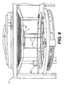
- Fig. 8 is a top view of the arrangement of Fig. 7, with a radiator located between the obstruction and the rotor;
- Fig. 9 is a side view of the arrangement of Fig. 8.
- Fig. 10 is an isometric view of the arrangement of Fig. 7;
- Fig. 11 is a schematic illustration of a rotor and obstruction arrangement, where the obstruction is located downstream of the rotor.
- Primary unsteady lift modes 16 are a function of the non-uniform flow and the characteristics of the rotor (e.g. the number of blades 14), and the characteristics of the blades 14, such as sweep, camber, thickness, and angle of attack.
- the primary unsteady lift modes create tonal noises at the BPF and its harmonics. Positioning one or more obstructions, such as obstructions 2B to 2E shown in Figs.
- Secondary unsteady lift modes 18 also generate noises.
- a secondary unsteady lift mode 18 By properly positioning the one or more obstructions in the non-uniform flow relative to the fan 12, it is possible to bring, for a selected tonal noise, a secondary unsteady lift mode 18 out of phase with a primary unsteady lift mode 16.
- the two unsteady lift modes 16, 18 are also of the same magnitude, the resulting unsteady lift mode 20 is zero, thereby eliminating the tonal noise. Should the secondary unsteady lift mode 18 not be perfectly out of phase and of the same magnitude as the primary unsteady lift mode 16, the tonal noise is nonetheless reduced. Determining the location of the one or more obstruction is achieved as described below.
- the rotor 10 of the fan 12 has four blades 14.
- the rotor 10 is first caused to rotate in the non-uniform flow causing the blades 14 to generate the tonal noises.
- the predominant tonal noise is the one generated at the BPF and is therefore the one which is normally selected to be attenuated.
- a number of obstructions 2 shown as rectangular obstructions for simplicity, are then positioned in the non-uniform flow upstream (as in Fig. 8 for example) or downstream (as in Fig.
- the number of obstructions 2 used to reduce the tonal noise at the BPF is preferably equal to the number of blades 14, therefore four rectangular obstructions 2 are used It is contemplated that a reduction in the tonal noise could also be achieved with a single obstruction 2 or a number of obstructions 2 which is less than the number of blades 14.
- the four rectangular obstructions 2 are preferably disposed in a circle 6 and, for a rotor 10 having blades 14 of equal pitch, are equally spaced from each other.
- the center of the circle 6 is preferably coaxial with the center 22 of the rotor 10.
- the obstructions 2 are initially disposed at a distance R1 from the center 22 of the rotor 10 and are located a certain axial distance away from the rotor 10. It is contemplated that the obstructions 2 could be located at the center 22 and extend away therefrom. It is also contemplated that a portion of the obstructions 2 could extend beyond the span length of the blades 14.
- Rotating the obstructions 2 around the center 22 changes the phase of the secondary unsteady lift mode 18, or noise, generated by the obstructions 2 and moving the obstructions 2 axially with respect to the rotor 10 changes the amplitude of the secondary unsteady lift mode 18, or noise, generated by the obstructions 2. Therefore to reduce the tonal noise, the obstructions 2 are rotated in a first direction. If the tonal noise is reduced, the obstructions 2 continue to be rotated as long as the tonal noise continues to be reduced. If the tonal noise increases when the obstructions 2 are rotated in the first direction, they are rotated in the opposite direction as long as the tonal noise continues to be reduced.
- the obstructions 2 When the obstructions 2 are at the location offering the most reduction in tonal noise, they are then moved in a first axial direction relative to the rotor 10. If the tonal noise is reduced, the obstructions 2 continue to be moved in the same axial direction as long as the tonal noise continues to be reduced. If the tonal noise increases when the obstructions 2 are moved in the first axial direction, they are moved in the opposite axial direction as long as the tonal noise continues to be reduced. The steps of rotating and axially moving the obstructions 2 are repeated until the desired level of reduction of tonal noise is obtained, bringing the obstructions 2 to a final position. Preferably, the desired level of reduction of the tonal noise is reached when the tonal noise is a minimum. It should be understood that the step of axially moving the obstructions 2 can be done before the step of rotating the obstructions 2. It is also contemplated that the radial distance R1 between the obstructions 2 and the center 22 could also be modified to reduce the tonal noise.
- the number of obstructions 2 is preferably an integer multiple of the number of blades 14 corresponding to an integer multiple of the corresponding harmonic for which the tonal noise is to be reduced.
- the number of obstructions 2 used is preferably twice the number of blades 14, therefore twelve obstructions would preferably be used, as shown in Fig. 1D.
- eighteen obstructions 2 would preferably be used.
- a first set 24 of obstructions 2 can first be positioned to reduce the tonal noise generated at the BPF, for example, and a second set 26 of obstructions 2 can then be positioned to reduce the tonal noise generated the first harmonic, for example.
- the obstructions 2 of each set 24, 26 are preferably of similar shape.
- the first set 24 would preferably have six obstructions 2, one possible example of which is shown in Fig. 1B, and the second set 26 would preferably have twelve obstructions 2, one possible example of which is shown in Fig. 1D.
- Fig. 1D As shown in Fig.
- the two sets 24, 26 of obstructions 2 can be positioned at different axial distances from the rotor 10. It is also contemplated that the two sets 24, 26 of obstructions 2 could be disposed at the same axial distance from the rotor 10, but at different radial distances from the center 22, such that one set is disposed inside the other.
- the arrangement of the sets is the same the one shown in Fig. 11.
- the first and second sets 24, 26 of obstructions 2 are positioned such that the secondary unsteady lift modes of the first and second sets 24, 26 result, when combined, in a combined unsteady lift mode that reduces the selected tonal noise.
- the combined secondary unsteady lift mode of the first and second sets 24, 26 results in an unsteady lift mode that has the same magnitude and is out of phase with the primary unsteady lift mode radiating noise at the selected tonal noise.
- This arrangement allows the desired level of reduction of tonal noise to be obtained by rotating the first and second sets 24, 26 around the central axis while maintaining the axial distance between the first and second sets 24, 26 and the rotor 10 constant. This is because changing the phase generated by one or both sets of obstructions 2 not only changes the phase of the combined unsteady lift mode but also the amplitude of the combined unsteady lift mode, even though the amplitude of the individual unsteady lift modes remain the same. Since the axial distance between the first and second sets 24, 26 and the rotor 10 do no need to be modified, the arrangement of the first and second sets 24, 26 and the rotor 10 can be more compact in the axial direction.
- the sets of obstructions 2 since the sets of obstructions 2 only need to be rotated, there is no need to provide actuators to move the sets of obstructions 2 in the axial direction in the case where the positioning of the obstructions 2 is to be automated. It is contemplated that more than two sets of obstructions could be used to reduce the same tonal noise. It is also contemplated that multiple sets of obstructions 2 could be used to reduce a first tonal noise and that multiple sets of obstructions 2 could be used to reduce a second tonal noise generated by the same rotor 10.
- a single obstruction 2 having a number of lobes 3, such as obstruction 2C shown in Fig. 1C it is also possible to use a single obstruction 2 having a number of lobes 3, such as obstruction 2C shown in Fig. 1C.
- the single obstruction 2 would preferably have six lobes 3, as shown in Fig. 1C.
- the single obstruction 2 would preferably have twelve lobes 3.
- the obstructions 2 when the obstructions 2 are located in the non-uniform flow, they generate noises, referred to as the harmonic content.
- Noise generated by the obstructions 2 at the frequency of the tonal noise which is selected to be reduced can be used to reduce it as mentioned above.
- noises are also generated by the obstructions 2 at other frequencies, including the harmonics of the rotor 10. Since the phase of these other noises cannot be adjusted, because they are set by the position of the obstructions 2 to reduce the selected tonal noise, they may interfere with the tonal noises generated at the higher harmonics so as to increase rather than reduce them. For this reason, care must be take in the design of the shapes of the obstructions 2.
- the obstructions 2 have to be shaped so that the predominant noise generated by the obstructions 2 is generated at the frequency of the tonal noise which is to be reduced.
- the noises generated by the obstructions 2 at the higher frequency are preferably negligible relative to the predominant noise in order to have little effect on the tonal noises generated by the rotor at the higher harmonics.
- the ratio of the predominant noise versus the other noises generated at the harmonics of the rotor 10 by the obstructions 2 can be expressed as a percentage.
- D % ⁇ n - 2 n m ⁇ a ⁇ x
- L is the unsteady lift mode
- N is the number of obstructions or lobes
- one or more obstructions need to be shaped such that their harmonic content rate D(%) is low so has to have a minimal effect on the higher harmonics of the rotor.
- the harmonic content rate D(%) is preferably less than 27%.
- the preferable harmonic rate may vary depending on the application. Also note that an obstruction generating a purely sinusoidal unsteady lift would have a harmonic content rate of zero.
- Fig. 5 provides an example of the normalized unsteady lift spectrum associated with various wake sizes at various circumferential orders for the interaction of the obstructions 2 with a six-bladed rotor 10.
- the circumferential order (w) is equal to the number of blades ( N ) multiplied by the circumferential order harmonic of N ( n ).
- the shape of the obstruction 2 affects the size of the wake. Generally, narrow obstructions 2 have narrow wakes, and wide obstructions 2 have wide wakes.
- the unsteady lift spectrum decreases much faster for obstructions 2 having a properly sized wake (shown by the circles) as the circumferential order increases, than for obstructions 2 having narrow (shown by the triangles) or wide (shown by the crosses) wakes.
- a properly sized obstructions 2 has less effect on the tonal noises generated at the higher harmonics than ones which are too narrow or too wide.
- Fig. 6 illustrates an example of the harmonic content rate for various wake widths.
- narrow and wide obstructions have a high harmonic content rate, which is undesirable for the reasons explained above.
- Figs. 1B, 1C, and 1E schematically illustrate obstructions having shapes that, when properly sized, would generate a low harmonic content rate when used to control the tonal noise generated at the BPF by a rotor 10 having six blades 14.
- Fig. 1D illustrates obstructions having shapes that, when properly sized, would generate a low harmonic content rate when used to control the tonal noise generated at the first harmonic by a rotor 10 having six blades 14, or at the BPF by a rotor 10 having 12 blades.
- Figs. 1B and 1D show trapezoidal obstructions 2B and 2D respectively disposed in a circle.
- Fig. 1C shows a sinusoidal obstruction 2C forming a ring and having six lobes 3.
- Fig. 1E shows an optimized set of shark fin shaped obstructions. It would be understood by a person skilled in the art that many other shapes and configurations of obstructions are possible which would also have a low harmonic content rate, such as three-dimensional obstructions.
- a single obstruction such as generally trapezoidal obstruction 2F shown in Fig. 1F
- a single obstruction 2F may lead to a higher harmonic content rate than the examples shown in Figs. 1B to 1E, it can nonetheless be positioned such that it controls a selected tonal noise.
- Such an arrangement would preferably be used at low rotation speeds of the rotor 10 and in cases where potential amplification of the higher harmonics is less of a concern.
- Figs. 7 to 10 illustrate one possible embodiment of an axial fan 12 having a rotor 10 and an obstruction 2 to reduce the tonal noise generated by the blades 14 of the rotor 10 when used in a non-uniform flow.
- the axial fan 12 is a radiator fan.
- a rotor 10 of the fan 12 has six blades 14. The blades 14 rotate inside a shroud 28. It is contemplated that no shroud could be provided.
- a radiator 30 located upstream of the rotor 10 and stator vanes 31 cause the non-uniform flow.
- a sinusoidal obstruction 2 similar to obstruction 2C of Fig. 1C, is mounted to a support 32 via rods 34. As shown in Fig.
- Fig. 11 schematically illustrates another way of mounting obstructions to a rotor 10.
- the rotor 10 turns around a fixed shaft 36, a set of obstructions, set 24 for example, is mounted on the shaft 36 so as to be rotated and translated thereon.
- the set 24 is fixed in place.
- the obstructions could be mounted inside a duct.
- the relatively small size of the obstruction 2 compared to the rotor 10 and the radiator 30 allows it to be easily located in a confined environment.
- actuators 38 and 40 can be used to automatically reposition the obstruction 2.
- Actuator 38 controls the translation of the obstruction 2
- actuator 40 controls the rotation of the obstruction 2.
- a sensor (not shown), in the form of a microphone for example, senses a variation in the tonal noise.
- the actuators 38, 40 move the obstruction 2 to a new position where the tonal noise is reduced to a desired level.
- the actuators 38, 40, sensor, and computer algorithm can also be used to provide the initial position of the obstruction 2.
Landscapes
- Engineering & Computer Science (AREA)
- Mechanical Engineering (AREA)
- General Engineering & Computer Science (AREA)
- Structures Of Non-Positive Displacement Pumps (AREA)
- Control Or Security For Electrophotography (AREA)
Abstract
Description
- The present application claims priority to
United States Provisional Patent Application No. 60/805,944 filed on June 27, 2006 - The present invention relates to a method and apparatus for controlling tonal noise from subsonic axial fans.
- Tonal noise mainly originates from flow irregularity (non-uniform flow) that causes circumferentially varying blade forces and gives rise to a considerably large radiated dipolar sound (tonal noise) at the blade passage frequency (BPF) and its harmonics. Although some axial fans operate in an environment where the flow is uniform, as schematically illustrated in Fig. 2A, in many instances, axial fans operate in a non-uniform flow, as schematically illustrated in Fig. 2B: this is the case, for example, of engine cooling fans that operate behind a radiator/condenser system or in the wake of inlet guide vanes.
- Techniques to control fan noise can be classified into two main families: active control or passive control. Passive methods are principally based on the geometrical characteristics of the propeller and its environment to reduce the noise generation mechanisms (reduce fluctuating forces or minimize their acoustic effects). Passive techniques can be considered as preventive techniques. However, it is not always possible to apply such modifications, especially in case of confined environments, such as automotive engine cooling fans. In such cases, active techniques have been proposed. Active techniques are effective at low frequencies, where passive techniques (such as using absorbing materials) are inefficient. Active techniques use the destructive interference between two waves to attenuate the noise. This is done by a secondary noise generated by a secondary source (loudspeaker for example) that interferes with the fan's primary noise. Active techniques can be considered as corrective techniques.
- A number of solutions for controlling tonal noise in axial fans have been proposed.
United States Patent No. 6,375,416 presents a technique and an apparatus based on sinusoidal circumferential variation of the tip clearance to create a unsteady pressure field opposite in phase with respect to the primary unsteady pressure field, thus reducing tonal noise. The proposed technique is based on sinusoidal variations of the inner surface of the shroud.United States Patent No. 5,692,702 describes a method as well as a system to control tonal noise generated by a ducted-rotor. The method relies on the introduction of upstream or downstream flow distortions to create an anti-sound opposite in phase with respect to the primary tonal noise. An acoustic signal from one or more microphone arrays provides information to adjust each circumferential modal component of the flow. Two methods for producing the distortions are proposed. The devices are mounted in a circumferential array on the duct wall and consist of either 1) nozzles actively exhausting or ingesting controlled amount of air or 2) rods with actively controlled protrusion into the flow. However, for the subject matter described in this patent, every modal components must be adjusted. - Figure 1A schematically illustrates an adaptation of another prior art solution. A number of
cylindrical rods 2A were mounted on a rotatable ring 4. Turning the ring 4 allowed for adjusting the phase of the control mode so that a reduction at the BPF was achieved when the two modes were out of phase. However, the wakes generated by therods 2 are salient, leading to a high harmonic content rate of the unsteady lift. Thus, the high harmonic content rate can lead to amplification of higher acoustic tones when attempting to control tonal noise at the BPF. - Therefore, there is a need for a passive method and apparatus for controlling a tonal noise which does not significantly amplify higher acoustic tones. There is also a need for a passive method and apparatus for controlling a tonal noise which can be used in a confined environment.
- One aspect of the present invention provides an apparatus for controlling a tonal noise which does not significantly amplify higher acoustic tones.
- In another aspect, the present invention provides an apparatus for controlling a tonal noise which can be used in a confined environment.
- A further aspect of the invention provides the use of one or more obstructions in a non-uniform flow to destructively interfere with a tonal noise generated by the blades of the rotor of an axial fan, and to provide a method for locating the one or more obstructions.
- In another aspect, the invention provides an axial flow fan having a rotor rotatable about an axis. The rotor has a number of blades. The number of blades generate a number of tonal noises when the rotor is rotating in a non-uniform flow, the number of tonal noises each having a phase and a magnitude. At least one obstruction is positioned at a first distance radially away from the axis and at a second distance axially away from the rotor. The at least one obstruction is positioned around the axis such that the at least one obstruction generates a second noise, when in the non-uniform flow, having a phase that is out of phase with the phase of one of the number of tonal noises. The second distance is selected such that a magnitude of the second noise is substantially equal to the magnitude of the one of the number of tonal noises. The at least one obstruction is shaped such that an interaction of the at least one obstruction with the rotor has a low harmonic content rate.
- In an additional aspect, the first distance is less than a span length of one of the number of blades.
- In a further aspect, the at least one obstruction is a sinusoidal obstruction forming a ring, the sinusoidal obstruction having a number of lobes.
- In an additional aspect, the at least one obstruction is a number of equally spaced obstructions disposed in a circle.
- In a further aspect, the harmonic content rate is less than 27%.
- In an additional aspect, the at least one obstruction is located upstream of the rotor.
- In a further aspect, the axial flow fan also has at least one other obstruction being positioned at a third distance radially away from the axis and at a fourth distance axially away from the rotor. The at least one other obstruction is positioned around the axis such that the at least one other obstruction generates a third noise, when in the non-uniform flow, having a phase that is out of phase with the phase of another of the number of tonal noises. The fourth distance is selected such that a magnitude of the third noise is substantially equal to the magnitude of the other of the number of tonal noises. The at least one other obstruction being shaped such that an interaction of the at least one other obstruction with the rotor has a low harmonic content rate.
- In an additional aspect, the axial flow fan also has an actuator for positioning the at least one obstruction.
- For purposes of this application, the terms "blade passage frequency" (or BPF) refer to the rate at which the blades of the rotor pass a fixed position . "Harmonics" are integer multiples of the BPF. For example, for a rotor having a BPF of 100Hz, the first harmonic is twice the BPF, or 200Hz, the second harmonic is thrice the BPF, or 300Hz, and so on. The "harmonic content rate", for the present application, is an indicator of the harmonic content of one or more obstructions. Obstructions having a low harmonic content rate do not significantly amplify tonal noise generated by the fan blades at harmonics higher than the one for which the obstructions were designed to reduce, and obstructions having a high harmonic content rate may significantly amplify tonal noise generated by the fan blades at harmonics higher than the one for which the obstructions were designed to reduce, as will be explained in greater details below.
- Embodiments of the present invention each have at least one of the above-mentioned aspects, but do not necessarily have all of them.
- Additional and/or alternative features, aspects, and advantages of the embodiments of the present invention will become apparent from the following description, the accompanying drawings, and the appended claims.
- Having thus generally described the nature of the present invention, reference will now be made to the accompanying drawings by way of illustration showing a preferred embodiment, in which:
- Fig. 1A is a schematic illustration of an arrangement of six cylindrical obstructions mounted to a ring which is an adaptation of a prior art arrangement;
- Fig. 1B is a schematic illustration of an arrangement in accordance with the present invention of six generally trapezoidal obstructions disposed in a circle;
- Fig. 1C is a schematic illustration of an arrangement in accordance with the present invention of a sinusoidal obstruction having six lobes;
- Fig. 1D is a schematic illustration of an arrangement in accordance with the present invention of twelve generally trapezoidal obstructions disposed in a circle;
- Fig. 1E is a schematic illustration of an arrangement in accordance with the present invention of six generally shark fin shaped obstructions disposed in a circle;
- Fig. 1F is a schematic illustration of an arrangement in accordance with the present invention of a single generally trapezoidal obstruction;
- Fig. 2A is a schematic illustration of a fan operating in a uniform flow;
- Fig. 2B is a schematic illustration of a fan operating in a uniform flow;
- Fig. 3 is a schematic illustration of the interaction between the unsteady lift modes of a fan and a set of obstructions shaped and positioned in accordance with the present invention;
- Fig. 4 is a schematic illustration of the positioning of obstructions relative to the rotor of a fan;
- Fig. 5 illustrates the unsteady lift spectra generated by various obstructions;
- Fig. 6 illustrates the harmonic rate content of trapezoidal obstructions having various widths;
- Fig. 7 is a front view of a rotor and obstruction arrangement, where the obstruction is located upstream of the rotor;
- Fig. 8 is a top view of the arrangement of Fig. 7, with a radiator located between the obstruction and the rotor;
- Fig. 9 is a side view of the arrangement of Fig. 8;
- Fig. 10 is an isometric view of the arrangement of Fig. 7; and
- Fig. 11 is a schematic illustration of a rotor and obstruction arrangement, where the obstruction is located downstream of the rotor.
- As explained above, when the
rotor 10 of afan 12 operates in a non-uniform flow, theblades 14 of therotor 10 experience changes in angles of attack during rotation. This leads to primaryunsteady lift modes 16, one order of which is schematically shown in Fig. 3. Primaryunsteady lift modes 16 are a function of the non-uniform flow and the characteristics of the rotor (e.g. the number of blades 14), and the characteristics of theblades 14, such as sweep, camber, thickness, and angle of attack. The primary unsteady lift modes create tonal noises at the BPF and its harmonics. Positioning one or more obstructions, such asobstructions 2B to 2E shown in Figs. 1B to 1E described in detail below, in the flow also creates unsteady lift modes, referred to as secondaryunsteady lift modes 18, one order of which is schematically shown if Fig. 3. Secondaryunsteady lift modes 18 also generate noises. By properly positioning the one or more obstructions in the non-uniform flow relative to thefan 12, it is possible to bring, for a selected tonal noise, a secondaryunsteady lift mode 18 out of phase with a primaryunsteady lift mode 16. As shown in Fig. 3, if the twounsteady lift modes unsteady lift mode 18 not be perfectly out of phase and of the same magnitude as the primaryunsteady lift mode 16, the tonal noise is nonetheless reduced. Determining the location of the one or more obstruction is achieved as described below. - The steps for determining the final location of the one or more obstructions will be described below with respect to Fig. 4. As seen in Fig. 4, the
rotor 10 of thefan 12 has fourblades 14. Therotor 10 is first caused to rotate in the non-uniform flow causing theblades 14 to generate the tonal noises. The predominant tonal noise is the one generated at the BPF and is therefore the one which is normally selected to be attenuated. However, as will be described below, it is possible to use the same technique to reduce the tonal noises generated at the harmonics. A number ofobstructions 2, shown as rectangular obstructions for simplicity, are then positioned in the non-uniform flow upstream (as in Fig. 8 for example) or downstream (as in Fig. 11 for example) of therotor 10. The number ofobstructions 2 used to reduce the tonal noise at the BPF is preferably equal to the number ofblades 14, therefore fourrectangular obstructions 2 are used It is contemplated that a reduction in the tonal noise could also be achieved with asingle obstruction 2 or a number ofobstructions 2 which is less than the number ofblades 14. The fourrectangular obstructions 2 are preferably disposed in acircle 6 and, for arotor 10 havingblades 14 of equal pitch, are equally spaced from each other. The center of thecircle 6 is preferably coaxial with the center 22 of therotor 10. Theobstructions 2 are initially disposed at a distance R1 from the center 22 of therotor 10 and are located a certain axial distance away from therotor 10. It is contemplated that theobstructions 2 could be located at the center 22 and extend away therefrom. It is also contemplated that a portion of theobstructions 2 could extend beyond the span length of theblades 14. - Rotating the
obstructions 2 around the center 22 changes the phase of the secondaryunsteady lift mode 18, or noise, generated by theobstructions 2 and moving theobstructions 2 axially with respect to therotor 10 changes the amplitude of the secondaryunsteady lift mode 18, or noise, generated by theobstructions 2. Therefore to reduce the tonal noise, theobstructions 2 are rotated in a first direction. If the tonal noise is reduced, theobstructions 2 continue to be rotated as long as the tonal noise continues to be reduced. If the tonal noise increases when theobstructions 2 are rotated in the first direction, they are rotated in the opposite direction as long as the tonal noise continues to be reduced. When theobstructions 2 are at the location offering the most reduction in tonal noise, they are then moved in a first axial direction relative to therotor 10. If the tonal noise is reduced, theobstructions 2 continue to be moved in the same axial direction as long as the tonal noise continues to be reduced. If the tonal noise increases when theobstructions 2 are moved in the first axial direction, they are moved in the opposite axial direction as long as the tonal noise continues to be reduced. The steps of rotating and axially moving theobstructions 2 are repeated until the desired level of reduction of tonal noise is obtained, bringing theobstructions 2 to a final position. Preferably, the desired level of reduction of the tonal noise is reached when the tonal noise is a minimum. It should be understood that the step of axially moving theobstructions 2 can be done before the step of rotating theobstructions 2. It is also contemplated that the radial distance R1 between theobstructions 2 and the center 22 could also be modified to reduce the tonal noise. - As mentioned above, it is also possible to use the same technique to reduce the tonal noise generated at harmonics of the BPF. In those cases, the number of
obstructions 2 is preferably an integer multiple of the number ofblades 14 corresponding to an integer multiple of the corresponding harmonic for which the tonal noise is to be reduced. For example, to reduce the tonal noise generated by the blades of a sixbladed rotor 10 at the first harmonic (which is twice the BPF), the number ofobstructions 2 used is preferably twice the number ofblades 14, therefore twelve obstructions would preferably be used, as shown in Fig. 1D. To reduce the tonal noise at the second harmonic (which is thrice the BPF) for a sixbladed rotor 10, eighteenobstructions 2 would preferably be used. - It is possible to combine multiple sets of
obstructions 2 to reduce multiple tonal noises, as shown in Fig. 11. Afirst set 24 ofobstructions 2 can first be positioned to reduce the tonal noise generated at the BPF, for example, and asecond set 26 ofobstructions 2 can then be positioned to reduce the tonal noise generated the first harmonic, for example. Theobstructions 2 of each set 24, 26 are preferably of similar shape. In the case of a six-bladed rotor 10, for the example given, thefirst set 24 would preferably have sixobstructions 2, one possible example of which is shown in Fig. 1B, and thesecond set 26 would preferably have twelveobstructions 2, one possible example of which is shown in Fig. 1D. As shown in Fig. 11, the twosets obstructions 2 can be positioned at different axial distances from therotor 10. It is also contemplated that the twosets obstructions 2 could be disposed at the same axial distance from therotor 10, but at different radial distances from the center 22, such that one set is disposed inside the other. - It is also possible to combine multiple sets of
obstructions 2 to reduce the same tonal noise. The arrangement of the sets is the same the one shown in Fig. 11. The first andsecond sets obstructions 2 are positioned such that the secondary unsteady lift modes of the first andsecond sets second sets second sets second sets rotor 10 constant. This is because changing the phase generated by one or both sets ofobstructions 2 not only changes the phase of the combined unsteady lift mode but also the amplitude of the combined unsteady lift mode, even though the amplitude of the individual unsteady lift modes remain the same. Since the axial distance between the first andsecond sets rotor 10 do no need to be modified, the arrangement of the first andsecond sets rotor 10 can be more compact in the axial direction. Also, since the sets ofobstructions 2 only need to be rotated, there is no need to provide actuators to move the sets ofobstructions 2 in the axial direction in the case where the positioning of theobstructions 2 is to be automated. It is contemplated that more than two sets of obstructions could be used to reduce the same tonal noise. It is also contemplated that multiple sets ofobstructions 2 could be used to reduce a first tonal noise and that multiple sets ofobstructions 2 could be used to reduce a second tonal noise generated by thesame rotor 10. - It is also possible to use a
single obstruction 2 having a number oflobes 3, such asobstruction 2C shown in Fig. 1C. In the case ofsingle obstructions 2 havinglobes 3, the above explanation regarding the preferred number ofobstructions 2 now apply to the number of lobes. Therefore, to reduce the tonal noise generated by a six-bladed fan at the BPF, thesingle obstruction 2 would preferably have sixlobes 3, as shown in Fig. 1C. To reduce the tonal noise generated by a six-bladed fan at the first harmonic (which is twice the BPF), thesingle obstruction 2 would preferably have twelvelobes 3. - As mentioned above, when the
obstructions 2 are located in the non-uniform flow, they generate noises, referred to as the harmonic content. Noise generated by theobstructions 2 at the frequency of the tonal noise which is selected to be reduced can be used to reduce it as mentioned above. However, noises are also generated by theobstructions 2 at other frequencies, including the harmonics of therotor 10. Since the phase of these other noises cannot be adjusted, because they are set by the position of theobstructions 2 to reduce the selected tonal noise, they may interfere with the tonal noises generated at the higher harmonics so as to increase rather than reduce them. For this reason, care must be take in the design of the shapes of theobstructions 2. Theobstructions 2 have to be shaped so that the predominant noise generated by theobstructions 2 is generated at the frequency of the tonal noise which is to be reduced. The noises generated by theobstructions 2 at the higher frequency are preferably negligible relative to the predominant noise in order to have little effect on the tonal noises generated by the rotor at the higher harmonics. The ratio of the predominant noise versus the other noises generated at the harmonics of therotor 10 by theobstructions 2 can be expressed as a percentage. This percentage is defined as the harmonic content rate D(%), and can be determined by the following equation:
where L is the unsteady lift mode, N is the number of obstructions or lobes, and n the circumferential order harmonic of N (n=1 for the BPF, n=2 for the first harmonic, ...). The unsteady lift modes can be determined by the following equation:
which uses the coordinate system illustrated in Fig. 4. The details and explanations regarding this equation are provided in the article entitled "Control of Tonal Noise From Subsonic Axial Fans Using Flow Control Obstructions. Part I: Interaction Between the Flow Control Obstructions and the Rotor". This article was annexed to the provisional application to which the present application claims priority. - Therefore one or more obstructions need to be shaped such that their harmonic content rate D(%) is low so has to have a minimal effect on the higher harmonics of the rotor. For example, in the case where obstructions are to be provided for a six-bladed automotive engine cooling fan having an inner radius of 6.25 cm, an outer radius of 15 cm, and swept blades, the harmonic content rate D(%) is preferably less than 27%. It should be noted that the preferable harmonic rate may vary depending on the application. Also note that an obstruction generating a purely sinusoidal unsteady lift would have a harmonic content rate of zero.
- Fig. 5 provides an example of the normalized unsteady lift spectrum associated with various wake sizes at various circumferential orders for the interaction of the
obstructions 2 with a six-bladed rotor 10. The circumferential order (w) is equal to the number of blades (N) multiplied by the circumferential order harmonic of N (n). The shape of theobstruction 2 affects the size of the wake. Generally,narrow obstructions 2 have narrow wakes, andwide obstructions 2 have wide wakes. As can be seen in Fig. 5, the unsteady lift spectrum decreases much faster forobstructions 2 having a properly sized wake (shown by the circles) as the circumferential order increases, than forobstructions 2 having narrow (shown by the triangles) or wide (shown by the crosses) wakes. Thus, a properlysized obstructions 2 has less effect on the tonal noises generated at the higher harmonics than ones which are too narrow or too wide. - Fig. 6 illustrates an example of the harmonic content rate for various wake widths. Here it can be seen that narrow and wide obstructions have a high harmonic content rate, which is undesirable for the reasons explained above.
- Figs. 1B, 1C, and 1E schematically illustrate obstructions having shapes that, when properly sized, would generate a low harmonic content rate when used to control the tonal noise generated at the BPF by a
rotor 10 having sixblades 14. Fig. 1D illustrates obstructions having shapes that, when properly sized, would generate a low harmonic content rate when used to control the tonal noise generated at the first harmonic by arotor 10 having sixblades 14, or at the BPF by arotor 10 having 12 blades. Figs. 1B and 1D showtrapezoidal obstructions sinusoidal obstruction 2C forming a ring and having sixlobes 3. Fig. 1E shows an optimized set of shark fin shaped obstructions. It would be understood by a person skilled in the art that many other shapes and configurations of obstructions are possible which would also have a low harmonic content rate, such as three-dimensional obstructions. - It is contemplated that a single obstruction, such as generally
trapezoidal obstruction 2F shown in Fig. 1F, could be used. Although using asingle obstruction 2F may lead to a higher harmonic content rate than the examples shown in Figs. 1B to 1E, it can nonetheless be positioned such that it controls a selected tonal noise. Such an arrangement would preferably be used at low rotation speeds of therotor 10 and in cases where potential amplification of the higher harmonics is less of a concern. - Figs. 7 to 10 illustrate one possible embodiment of an
axial fan 12 having arotor 10 and anobstruction 2 to reduce the tonal noise generated by theblades 14 of therotor 10 when used in a non-uniform flow. In these figures, theaxial fan 12 is a radiator fan. Arotor 10 of thefan 12 has sixblades 14. Theblades 14 rotate inside ashroud 28. It is contemplated that no shroud could be provided. Aradiator 30 located upstream of therotor 10 andstator vanes 31 cause the non-uniform flow. Asinusoidal obstruction 2, similar toobstruction 2C of Fig. 1C, is mounted to asupport 32 viarods 34. As shown in Fig. 7, thesupport 32 can be rotated and translated to properly position theobstruction 2 to reduce the tonal noise generated by therotor 10 due to the non-uniform flow. Once the amount of reduction is obtained, thesupport 32 is fixed in place. Fig. 11 schematically illustrates another way of mounting obstructions to arotor 10. In Fig. 11, therotor 10 turns around a fixedshaft 36, a set of obstructions, set 24 for example, is mounted on theshaft 36 so as to be rotated and translated thereon. Once the desired amount of reduction of the tonal noise is obtained, theset 24 is fixed in place. Alternatively, the obstructions could be mounted inside a duct. - As can be seen in Figs. 7 to 10, the relatively small size of the
obstruction 2 compared to therotor 10 and theradiator 30 allows it to be easily located in a confined environment. - Although the above example shows the use of obstructions with a radiator fan, the obstructions and method of locating them can be used in almost any subsonic axial fan. Computer fans, aircraft propellers, and fans of turbo-fan aircraft engines are only some examples of applications where the obstructions described herein could be used.
- Over time the non-uniform flow in some applications may change. For example, flies get caught in the radiator of a car, or dust gather on the fan of a computer. This change in the non-uniform flow will result in a change in the primary unsteady lift modes of the
rotor 10. Depending on the degree of variation, theobstruction 2 may need to be repositioned. Returning to Figs. 7 to 10,actuators obstruction 2.Actuator 38 controls the translation of theobstruction 2, andactuator 40 controls the rotation of theobstruction 2. A sensor (not shown), in the form of a microphone for example, senses a variation in the tonal noise. Through a computer algorithm which replicates the steps described above to initially position theobstruction 2, theactuators obstruction 2 to a new position where the tonal noise is reduced to a desired level. Theactuators obstruction 2. - Modifications and improvements to the above-described embodiments of the present invention may become apparent to those skilled in the art. The foregoing description is intended to be exemplary rather than limiting. The scope of the present invention is therefore intended to be limited solely by the scope of the appended claims.
Claims (10)
- An axial flow fan comprising:a rotor rotatable about an axis, the rotor having a number of blades, the number of blades generating a number of tonal noises when the rotor is rotating in a non-uniform flow, the number of tonal noises each having a phase and a magnitude; andat least one obstruction being positioned at a first distance radially away from the axis and at a second distance axially away from the rotor,the axial flow fan being characterized in that:the at least one obstruction is positioned around the axis such that the at least one obstruction generates a second noise, when in the non-uniform flow, having a phase that is out of phase with the phase of one of the number of tonal noises,the second distance is selected such that a magnitude of the second noise is substantially equal to the magnitude of the one of the number of tonal noises, andthe at least one obstruction is shaped such that an interaction of the at least one obstruction with the rotor has a low harmonic content rate.
- The axial flow fan of claim 1, wherein the first distance is less than a span length of one of the number of blades.
- The axial flow fan of claim 1 or 2, wherein the at least one obstruction is a sinusoidal obstruction forming a ring, the sinusoidal obstruction having a number of lobes.
- The axial flow fan of claim 3, wherein the number of lobes of the sinusoidal obstruction is equal to the number of blades of the rotor.
- The axial flow fan of claim 1 or 2, wherein the at least one obstruction is a number of equally spaced obstructions disposed in a circle.
- The axial flow fan of claim 5, wherein the number of obstructions is equal to the number of blades of the rotor.
- The axial flow fan of any one of claims 1 to 6, wherein the harmonic content rate is less than 27%.
- The axial flow fan of any one of claims 1 to 7, wherein the at least one obstruction is located upstream of the rotor.
- The axial flow fan of any one of claims 1 to 8, further comprising:at least one other obstruction being positioned at a third distance radially away from the axis and at a fourth distance axially away from the rotor,the at least one other obstruction being positioned around the axis such that the at least one other obstruction generates a third noise, when in the non-uniform flow, having a phase that is out of phase with the phase of another of the number of tonal noises,the fourth distance being selected such that a magnitude of the third noise is substantially equal to the magnitude of the other of the number of tonal noises, andthe at least one other obstruction being shaped such that an interaction of the at least one other obstruction with the rotor has a low harmonic content rate.
- The axial flow fan of any one of claims 1 to 9, further comprising an actuator for positioning the at least one obstruction.
Applications Claiming Priority (1)
| Application Number | Priority Date | Filing Date | Title |
|---|---|---|---|
| US80594406P | 2006-06-27 | 2006-06-27 |
Publications (2)
| Publication Number | Publication Date |
|---|---|
| EP1995470A2 true EP1995470A2 (en) | 2008-11-26 |
| EP1995470A3 EP1995470A3 (en) | 2010-09-08 |
Family
ID=38543540
Family Applications (1)
| Application Number | Title | Priority Date | Filing Date |
|---|---|---|---|
| EP07012624A Withdrawn EP1995470A3 (en) | 2006-06-27 | 2007-06-27 | Method and apparatus for controlling tonal noise from subsonic axial fans |
Country Status (2)
| Country | Link |
|---|---|
| EP (1) | EP1995470A3 (en) |
| CA (1) | CA2593382A1 (en) |
Cited By (3)
| Publication number | Priority date | Publication date | Assignee | Title |
|---|---|---|---|---|
| WO2014118058A1 (en) * | 2013-01-30 | 2014-08-07 | Siemens Aktiengesellschaft | Gas turbine inlet silencer |
| CN114056559A (en) * | 2016-12-30 | 2022-02-18 | Wing航空有限责任公司 | Rotor unit with asymmetric rotor blades |
| CN116857210A (en) * | 2023-07-05 | 2023-10-10 | 上海交通大学 | Be used for acoustic mode modulation to fall radiator fan frame of making an uproar |
Family Cites Families (2)
| Publication number | Priority date | Publication date | Assignee | Title |
|---|---|---|---|---|
| DE3609212A1 (en) * | 1986-03-19 | 1987-09-24 | Standard Elektrik Lorenz Ag | AXIAL FAN |
| US6883233B2 (en) * | 2000-07-11 | 2005-04-26 | Lg Electronics Inc | Fan guide |
-
2007
- 2007-06-27 CA CA002593382A patent/CA2593382A1/en not_active Abandoned
- 2007-06-27 EP EP07012624A patent/EP1995470A3/en not_active Withdrawn
Cited By (4)
| Publication number | Priority date | Publication date | Assignee | Title |
|---|---|---|---|---|
| WO2014118058A1 (en) * | 2013-01-30 | 2014-08-07 | Siemens Aktiengesellschaft | Gas turbine inlet silencer |
| CN114056559A (en) * | 2016-12-30 | 2022-02-18 | Wing航空有限责任公司 | Rotor unit with asymmetric rotor blades |
| CN114056559B (en) * | 2016-12-30 | 2024-06-11 | Wing航空有限责任公司 | Rotor unit with asymmetrical rotor blades |
| CN116857210A (en) * | 2023-07-05 | 2023-10-10 | 上海交通大学 | Be used for acoustic mode modulation to fall radiator fan frame of making an uproar |
Also Published As
| Publication number | Publication date |
|---|---|
| EP1995470A3 (en) | 2010-09-08 |
| CA2593382A1 (en) | 2007-12-27 |
Similar Documents
| Publication | Publication Date | Title |
|---|---|---|
| US5342167A (en) | Low noise fan | |
| US6375416B1 (en) | Technique for reducing acoustic radiation in turbomachinery | |
| US20170274980A1 (en) | Variable pitch bladed disc | |
| EP0784845A1 (en) | Active control of aircraft engine inlet noise using compact sound sources and distributed error sensors | |
| Darvish et al. | Numerical and experimental study on the tonal noise generation of a radial fan | |
| US11415152B2 (en) | System for reducing interference noise of rotor and stator blades, and flight vehicle | |
| US8777560B2 (en) | Method and apparatus for controlling tonal noise from subsonic fans | |
| US20170335852A1 (en) | Fan with integral acoustic treatment | |
| US20080008592A1 (en) | Method and apparatus for controlling tonal noise from subsonic axial fans | |
| Wang et al. | Experimental investigation of ducted fan noise control by turbulence grids insertion between propellers and struts | |
| Sun et al. | Design of sinusoidal-shaped inlet duct for acoustic mode modulation noise reduction of cooling fan | |
| EP1995470A2 (en) | Method and apparatus for controlling tonal noise from subsonic axial fans | |
| Fitzgerald et al. | Reduction of discrete frequency noise in small, subsonic axial‐flow fans | |
| US20170284205A1 (en) | Variable pitch bladed disc | |
| Liu et al. | Reactive control of subsonic axial fan noise in a duct | |
| Gérard et al. | Experimental validation of tonal noise control from subsonic axial fans using flow control obstructions | |
| Wang et al. | Noise source analysis and control of two axial-flow cooling fans in series | |
| Gérard et al. | Tonal noise control from centrifugal fans using flow control obstructions | |
| JP6151901B2 (en) | Noise reduction in turbomachines and related methods | |
| Gérard et al. | Use of a beat effect for the automatic positioning of flow obstructions to control tonal fan noise: theory and experiments | |
| Geng et al. | Stability enhancement of an axial fan by foam metal casing treatment subjected to circumferential inlet distortion | |
| Gorny et al. | Axial fan blade tone cancellation using optimally tuned quarter wavelength resonators | |
| CN112524058B (en) | Fan outer frame structure for inhibiting noise of cooling fan and modeling method thereof | |
| Bianchi et al. | Far-field radiation of tip aerodynamic sound sources in axial fans fitted with passive noise control features | |
| Kota et al. | Wake generator control of inlet flow to cancel flow distortion noise |
Legal Events
| Date | Code | Title | Description |
|---|---|---|---|
| PUAI | Public reference made under article 153(3) epc to a published international application that has entered the european phase |
Free format text: ORIGINAL CODE: 0009012 |
|
| AK | Designated contracting states |
Kind code of ref document: A2 Designated state(s): AT BE BG CH CY CZ DE DK EE ES FI FR GB GR HU IE IS IT LI LT LU LV MC MT NL PL PT RO SE SI SK TR |
|
| AX | Request for extension of the european patent |
Extension state: AL BA HR MK RS |
|
| PUAL | Search report despatched |
Free format text: ORIGINAL CODE: 0009013 |
|
| AK | Designated contracting states |
Kind code of ref document: A3 Designated state(s): AT BE BG CH CY CZ DE DK EE ES FI FR GB GR HU IE IS IT LI LT LU LV MC MT NL PL PT RO SE SI SK TR |
|
| AX | Request for extension of the european patent |
Extension state: AL BA HR MK RS |
|
| RIC1 | Information provided on ipc code assigned before grant |
Ipc: F04D 29/66 20060101AFI20071009BHEP Ipc: G10K 11/178 20060101ALI20100730BHEP Ipc: F04D 29/52 20060101ALI20100730BHEP |
|
| 17P | Request for examination filed |
Effective date: 20110304 |
|
| AKX | Designation fees paid |
Designated state(s): AT BE BG CH CY CZ DE DK EE ES FI FR GB GR HU IE IS IT LI LT LU LV MC MT NL PL PT RO SE SI SK TR |
|
| STAA | Information on the status of an ep patent application or granted ep patent |
Free format text: STATUS: REQUEST FOR EXAMINATION WAS MADE |
|
| STAA | Information on the status of an ep patent application or granted ep patent |
Free format text: STATUS: THE APPLICATION IS DEEMED TO BE WITHDRAWN |
|
| 18D | Application deemed to be withdrawn |
Effective date: 20160105 |