EP1994907A1 - Try-in implant - Google Patents
Try-in implant Download PDFInfo
- Publication number
- EP1994907A1 EP1994907A1 EP07010034A EP07010034A EP1994907A1 EP 1994907 A1 EP1994907 A1 EP 1994907A1 EP 07010034 A EP07010034 A EP 07010034A EP 07010034 A EP07010034 A EP 07010034A EP 1994907 A1 EP1994907 A1 EP 1994907A1
- Authority
- EP
- European Patent Office
- Prior art keywords
- implant
- try
- crown
- cap
- attachment portion
- Prior art date
- Legal status (The legal status is an assumption and is not a legal conclusion. Google has not performed a legal analysis and makes no representation as to the accuracy of the status listed.)
- Granted
Links
- 239000007943 implant Substances 0.000 title claims abstract description 97
- 229920002994 synthetic fiber Polymers 0.000 claims description 9
- 239000004696 Poly ether ether ketone Substances 0.000 claims description 7
- 229920002530 polyetherether ketone Polymers 0.000 claims description 7
- 229910052751 metal Inorganic materials 0.000 claims description 6
- 239000002184 metal Substances 0.000 claims description 6
- -1 Grilamid TR 70 LX Chemical compound 0.000 claims description 5
- 230000002265 prevention Effects 0.000 claims description 5
- 229920000642 polymer Polymers 0.000 claims description 4
- 229920000491 Polyphenylsulfone Polymers 0.000 claims description 3
- 239000000919 ceramic Substances 0.000 claims description 3
- 229920001343 polytetrafluoroethylene Polymers 0.000 claims description 3
- 239000002131 composite material Substances 0.000 claims description 2
- JUPQTSLXMOCDHR-UHFFFAOYSA-N benzene-1,4-diol;bis(4-fluorophenyl)methanone Chemical compound OC1=CC=C(O)C=C1.C1=CC(F)=CC=C1C(=O)C1=CC=C(F)C=C1 JUPQTSLXMOCDHR-UHFFFAOYSA-N 0.000 claims 2
- 239000004810 polytetrafluoroethylene Substances 0.000 claims 1
- 238000007788 roughening Methods 0.000 claims 1
- 230000000007 visual effect Effects 0.000 description 5
- 241000628997 Flos Species 0.000 description 4
- 229920006324 polyoxymethylene Polymers 0.000 description 4
- PNEYBMLMFCGWSK-UHFFFAOYSA-N Alumina Chemical compound [O-2].[O-2].[O-2].[Al+3].[Al+3] PNEYBMLMFCGWSK-UHFFFAOYSA-N 0.000 description 3
- RTAQQCXQSZGOHL-UHFFFAOYSA-N Titanium Chemical compound [Ti] RTAQQCXQSZGOHL-UHFFFAOYSA-N 0.000 description 3
- 238000002513 implantation Methods 0.000 description 3
- 239000010936 titanium Substances 0.000 description 3
- 239000004698 Polyethylene Substances 0.000 description 2
- 229920002873 Polyethylenimine Polymers 0.000 description 2
- 239000004743 Polypropylene Substances 0.000 description 2
- QCWXUUIWCKQGHC-UHFFFAOYSA-N Zirconium Chemical compound [Zr] QCWXUUIWCKQGHC-UHFFFAOYSA-N 0.000 description 2
- MCMNRKCIXSYSNV-UHFFFAOYSA-N Zirconium dioxide Chemical compound O=[Zr]=O MCMNRKCIXSYSNV-UHFFFAOYSA-N 0.000 description 2
- 238000004873 anchoring Methods 0.000 description 2
- TZCXTZWJZNENPQ-UHFFFAOYSA-L barium sulfate Chemical compound [Ba+2].[O-]S([O-])(=O)=O TZCXTZWJZNENPQ-UHFFFAOYSA-L 0.000 description 2
- 239000004053 dental implant Substances 0.000 description 2
- 210000004513 dentition Anatomy 0.000 description 2
- 210000004283 incisor Anatomy 0.000 description 2
- 239000000463 material Substances 0.000 description 2
- 210000004400 mucous membrane Anatomy 0.000 description 2
- 239000004417 polycarbonate Substances 0.000 description 2
- 229910001220 stainless steel Inorganic materials 0.000 description 2
- 239000010935 stainless steel Substances 0.000 description 2
- 238000011477 surgical intervention Methods 0.000 description 2
- 229910052719 titanium Inorganic materials 0.000 description 2
- 230000036346 tooth eruption Effects 0.000 description 2
- 229910052726 zirconium Inorganic materials 0.000 description 2
- 229910000619 316 stainless steel Inorganic materials 0.000 description 1
- VYZAMTAEIAYCRO-UHFFFAOYSA-N Chromium Chemical compound [Cr] VYZAMTAEIAYCRO-UHFFFAOYSA-N 0.000 description 1
- 229910000531 Co alloy Inorganic materials 0.000 description 1
- 229910001200 Ferrotitanium Inorganic materials 0.000 description 1
- 241001484259 Lacuna Species 0.000 description 1
- 229930040373 Paraformaldehyde Natural products 0.000 description 1
- 229910000883 Ti6Al4V Inorganic materials 0.000 description 1
- 229910045601 alloy Inorganic materials 0.000 description 1
- 239000000956 alloy Substances 0.000 description 1
- 229910052804 chromium Inorganic materials 0.000 description 1
- 239000011651 chromium Substances 0.000 description 1
- 229910017052 cobalt Inorganic materials 0.000 description 1
- 239000010941 cobalt Substances 0.000 description 1
- GUTLYIVDDKVIGB-UHFFFAOYSA-N cobalt atom Chemical compound [Co] GUTLYIVDDKVIGB-UHFFFAOYSA-N 0.000 description 1
- 230000001419 dependent effect Effects 0.000 description 1
- 229910052735 hafnium Inorganic materials 0.000 description 1
- VBJZVLUMGGDVMO-UHFFFAOYSA-N hafnium atom Chemical compound [Hf] VBJZVLUMGGDVMO-UHFFFAOYSA-N 0.000 description 1
- 208000006454 hepatitis Diseases 0.000 description 1
- 231100000283 hepatitis Toxicity 0.000 description 1
- 208000015181 infectious disease Diseases 0.000 description 1
- 238000001746 injection moulding Methods 0.000 description 1
- 238000009434 installation Methods 0.000 description 1
- 230000007774 longterm Effects 0.000 description 1
- 150000002739 metals Chemical class 0.000 description 1
- 238000000034 method Methods 0.000 description 1
- 210000005036 nerve Anatomy 0.000 description 1
- 229910052758 niobium Inorganic materials 0.000 description 1
- 239000010955 niobium Substances 0.000 description 1
- GUCVJGMIXFAOAE-UHFFFAOYSA-N niobium atom Chemical compound [Nb] GUCVJGMIXFAOAE-UHFFFAOYSA-N 0.000 description 1
- 230000003287 optical effect Effects 0.000 description 1
- RVTZCBVAJQQJTK-UHFFFAOYSA-N oxygen(2-);zirconium(4+) Chemical compound [O-2].[O-2].[Zr+4] RVTZCBVAJQQJTK-UHFFFAOYSA-N 0.000 description 1
- 229920000515 polycarbonate Polymers 0.000 description 1
- 229920000573 polyethylene Polymers 0.000 description 1
- 229920001155 polypropylene Polymers 0.000 description 1
- 229910052573 porcelain Inorganic materials 0.000 description 1
- 229910052715 tantalum Inorganic materials 0.000 description 1
- GUVRBAGPIYLISA-UHFFFAOYSA-N tantalum atom Chemical compound [Ta] GUVRBAGPIYLISA-UHFFFAOYSA-N 0.000 description 1
- 229910001928 zirconium oxide Inorganic materials 0.000 description 1
Images




Classifications
-
- A—HUMAN NECESSITIES
- A61—MEDICAL OR VETERINARY SCIENCE; HYGIENE
- A61C—DENTISTRY; APPARATUS OR METHODS FOR ORAL OR DENTAL HYGIENE
- A61C8/00—Means to be fixed to the jaw-bone for consolidating natural teeth or for fixing dental prostheses thereon; Dental implants; Implanting tools
- A61C8/0089—Implanting tools or instruments
-
- A—HUMAN NECESSITIES
- A61—MEDICAL OR VETERINARY SCIENCE; HYGIENE
- A61C—DENTISTRY; APPARATUS OR METHODS FOR ORAL OR DENTAL HYGIENE
- A61C1/00—Dental machines for boring or cutting ; General features of dental machines or apparatus, e.g. hand-piece design
- A61C1/08—Machine parts specially adapted for dentistry
- A61C1/082—Positioning or guiding, e.g. of drills
- A61C1/084—Positioning or guiding, e.g. of drills of implanting tools
Definitions
- the present invention relates to a try-in implant for verifying position and angulation of a pilot hole.
- US 5,208,845 discloses a radiographic depth gauge for positioning dental implants in a jaw bone.
- the gauge is formed of a material, which is x-ray visible, and is an elongated member with distance markings. The gauge both shows the depth and angulation of the drill hole relative to other holes and existing dentition.
- US 5,842,859 discloses an indication device for marking and forming one or more attachment points for one or more fixtures, which can be fitted into a receiving hole in which it bears via a bearing part. At least one indicating part is interconnected with the protruding part and has a free end extending away from the existing hole, where a location of the new hole to be used as an attachment point is established at a position substantially adjacent to an exterior surface of the free end of the indicating part.
- Said try-in implant comprises a body portion to be received in a pilot hole, a neck portion formed above said body portion, whereby said neck portion has a sufficient length to project through mucosal tissue above said pilot hole, and an attachment portion formed above said neck portion.
- Said attachment portion comprises a crown-like cap.
- Said try-in implant indicates the exact geometry of the implant's prosthetic portion together with the mounted crown. Due to the optical identity or similarity of the try-in implant and the tooth prosthesis, meaning the final implant and the mounted crown, the surgeon has during the surgical intervention a visual impression of the situation after implantation and restoration.
- a mounted crown can be rudimentary minimal (a crown framework) or like the final crown (a final porcelain veneering crown of average/generic shape). This enables an easier decision about the implant to be selected.
- Possible implants are one-part implants or two-part implants, they may have a straight or angulated mounting part and the length and/or diameter of the implants to be selected may also be determined.
- the facial-lingual and mesial-distal, corona-apical and apical-incisal position as well as the distance to adjacent teeth and implants can be verified with a try-in implant according to the present invention. Functional and aesthetic long-term results can be predicted due to the use of such a try-in implant.
- the crown-like cap is an integral part of the attachment portion, preferably the whole try-in implant is formed in one piece. This can be obtained for example if the try-in implant is obtained by injection molding.
- the crown-like cap is a separate component which is mounted on the attachment portion, for example by a snap fit assembly.
- a snap fit assembly it is possible to mount different forms of crown-like caps on the attachment portion in order to determine the optimal shape of the crown.
- crown-like cap and the attachment portion are one separate component which is mounted on the neck portion.
- one separate component is formed by the crown-like cap, the attachment portion and the neck portion, which is mounted on the body portion.
- the crown-like cap comprises a handle to ensure easy and safe handling of said try-in implant.
- the handle is preferable integrated on the top of the crown-like cap.
- the handle on the crown-like cap ensures that the try-in implant can easily be inserted in the pilot hole, that means the first receiving hole or drill hole, by hand or by tweezers without being lost in the patient's mouth, thereby ensuring a safe handling.
- the handle is an integral part of the crown-like cap by at least partly gripping the surface of the crown-like cap to ensure that the try-in implant can not slip away during the handling procedure in the patient's mouth.
- the handle or the crown-like cap comprises an opening for the prevention of aspiration.
- a thread or floss may be inserted through the opening and held outside a patient's mouth.
- the thread or floss can be used to assist in removing the try-in implant.
- the try-in implants have the same diameters as the implants. That means that that the body portion of the try-in implant according to the present invention has a diameter from 1.0 to 8.0 mm, preferably consisting of the group of 2.2 mm, 3.0 mm, 3.5 mm, 4.2 mm, 5 mm and 5.5 mm. Especially preferred are those having a diameter from 2.0 to 3.0 mm, for example 2.2mm and 2.8 mm.
- the body of try-in implant may have different length, preferably 6 mm and 8 mm. It is also possible that the try-in implants comprise a height indicator, designed with horizontal or lacuna markings. Such a height indicator makes it possible to decide whether an adjustment of the pilot hole is necessary, respectively which implant length has to be selected.
- the try-in implants according to the present invention have, depending on their diameter and size, a specific color, which serves as color code. Alternatively they have a tooth-like colour to support the visual impression.
- the try-in implant comprises mainly a metal selected from the group consisting of titanium, zirconium, stainless steel preferably titanium or stainless steel.
- the implants comprise an alloy of metals selected from the group consisting of cobalt, chromium, titanium, zirconium, niobium, hafnium or tantalum.
- Most preferred are 316 stainless steel, Ti6Al4V, Ti6Al7Nb and a Cr-Co alloy.
- the try-in implant is made of a synthetic material.
- the synthetic material is selected from the group consisting of ceramic such as aluminium oxide or zirconium oxide, composite materials as well as polymers, especially biocompatible USP Class 6 compliant polymers, such as PEEK (polyetheretherketone), POM(polyoxymethylene), Grilamid TR 70 LX of EMS, PEI of Sulzer Medica (polyethylene imine), PTFE (polytetrafluorethylene), PP (polypropylene), PMP (polymethylpenten), PPSU (polyphenylsulfone), PE (polyethylene), and PC (polycarbonate).
- the implant is made of PEEK or POM.
- series of x-rays are taken in order to determine where and how to position implants in the jaw bone without damaging surrounding structures such as the nerves in the lower jaw bone and the sinuses adjacent the upper jaw bone. Based on said x-ray the pilot hole is drilled in the jaw bone.
- the try-in implant is made of a metal or synthetic material, which is X-ray visible
- a further x-ray can be taken to determine the angulation of the pilot hole relative to existing dentition and the depth of the pilot hole relative to anatomical restriction.
- a possible synthetic material, which is X-ray visible is BaSO 4 containing PEEK or ZrO 2 itself.
- X-ray visibility of the try-implant according to the present invention permits optimal selection of the implant (one-part vs. two-part, straight or angled abutment as well as length of the implant) as well as the precision placement of implants to their maximum depth in the jaw bone to assure a maximum strength supporting for one or more dental restorations.
- the try-in implants can be sterilized and therefore be used several times.
- Figure 1 shows a final implant 1 with a mounted crown 5 according to the state of the art. It comprises an anchoring part 10 with a threaded section, a neck part 15 and a mounting part 20. On the mounting part 20 the crown 5 is attached.
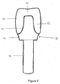
- FIG. 2 shows a try-in implant 30 according to the present invention.
- Said try-in implant 30 comprises a body portion 35 to be received in a pilot hole.
- the body portion 35 corresponds to the anchoring part 10 with a threaded section of the final implant.
- a neck portion 40 is formed which may comprise a slightly enlarged conical section, with a sufficient length to project through mucosal tissue above the pilot hole.
- an attachment portion 45 is formed, which corresponds to the mounting part 20 of the final implant.
- Said attachment portion 45 comprises a crown-like cap 50, resulting in a visual impression, which corresponds to the situation after the implantation and restoration.
- the crown-like cap 50 may have various forms corresponding to the different teeth, that is, the form of a premolar crown, incisor crown, rudimentary framework, generic shape etc.
- a premolar crown-like cap is shown in figure 2 .
- the crown-like cap may be a separate component of the try-in implant. That means that it can be attached on the attachment portion 45 before inserting in the pilot whole.
- the surgeon may select from crown-like caps 50 with different wall thickness, whereby said wall thickness depends on minimal framework versus complete crown and on material of crown (metal or ceramics).
- the wall thickness on the side 55 of the crown-like cap 50 varies from 0.3 mm to 2 mm and the wall thickness on the top 60 of the crown-like cap 50 varies from 0.8 mm to 6 mm.
- the try-in implant 30 is made of a biocompatible metal or synthetic material as mentioned above. Preferably it is made of PEEK or POM.
- FIG 3 shows an embodiment according to the present invention, which is only slightly different from that shown in figure 2 .
- the crown-like cap 50 is an integral part of the attachment portion 45.
- Preferably the whole try-in implant is formed in one piece.
- Such a try-in implant can be produced at low cost, which is especially preferred if the try-in implant is designed as one-way product.
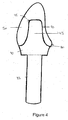
- Figure 4 shows a try-in implant with an incisor crown-like cap 50. Similar to the embodiment shown in figure 2 the surgeon may select from crown-like cap 50 with different wall thickness, whereby the wall thickness on the side 70 of the crown-like cap 50 varies from 0.3 mm to 2 mm, the wall thickness 75 of the crown-like cap 50 varies from 0.5 mm to 2 mm and the wall thickness at the bottom 80 of the crown-like cap 50 varies from 0.05 to 0.5 mm.
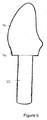
- Figure 5 shows an embodiment according to the present invention, which is only slightly different from that shown in figure 4 .
- the crown-like cap 50 is an integral part of the attachment portion 45.
- Figure 6 shows a further preferred embodiment of the present invention, wherein the crown-like cap 50, which may be a separate or an integral part of the attachment portion, comprises a handle 85.
- the handle 85 may be an integral part of the crown-like cap 50 as shown in figure 6 or mounted on the crown-like cap 50 as shown in figure 8 .
- the crown-like cap may comprise a cavity, which allows a better gripping for example by tweezers.
- the handle 85 is an integral part of the crown-like cap 50, said crown-like cap 50 has a partly or fully gripping surface.
- Such a try-in implant can be easily inserted in the pilot hole by hand or by tweezers without being lost in the patient's mouth, thereby ensuring a safe handling.
- FIG. 7 shows a further embodiment of the present invention, wherein the crown-like cap 50 is a separate component. Said crown-like cap 50 is attached on the attachment portion by a snap-fit assembly 90 which ensures that the crown-like cap does not shift away in the patient's mouth.
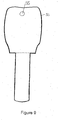
- Figure 8 shows a further embodiment of the present invention, wherein the handle 85 is attached on the crown-like cap 50.
- the handle 85 may have various forms, which can easily be gripped by hand or by tweezers, such as T-shape, triangular, rectangular, squarish, circular or semicircular.
- the handle 85 has a gripping surface.
- the handle 85 may be integrated.
- Figure 9 shows a try-in implant 30, wherein the crown-like cap 50 comprises an opening 95 for the prevention of aspiration.
- a thread or floss may be inserted through the opening 20 and held outside the patient's mouth. Additionally, the thread or floss may be used to assist in removing the try-in implant in a safe and quick way.
- a handle as shown in figures 6 and 8 may comprise an opening 95 for the prevention of aspiration.
Landscapes
- Health & Medical Sciences (AREA)
- Oral & Maxillofacial Surgery (AREA)
- General Health & Medical Sciences (AREA)
- Epidemiology (AREA)
- Life Sciences & Earth Sciences (AREA)
- Animal Behavior & Ethology (AREA)
- Dentistry (AREA)
- Public Health (AREA)
- Veterinary Medicine (AREA)
- Orthopedic Medicine & Surgery (AREA)
- Prostheses (AREA)
- Diaphragms For Electromechanical Transducers (AREA)
- Steroid Compounds (AREA)
- Crystals, And After-Treatments Of Crystals (AREA)
- Rehabilitation Tools (AREA)
Abstract
Description
- The present invention relates to a try-in implant for verifying position and angulation of a pilot hole.
- When installing dental implants, the positioning of the implant is extremely important to obtain a good aesthetic and functional result. The positioning of the implant to a large extent determines the choice of prosthetic components. In order to provide guidance for the surgeon during the installation of an implant, various types of so-called surgical guide rails have traditionally been used. These guide rails are mainly to be produced under laboratory conditions and can be made in a number of different designs. As aids during the surgical intervention it is also possible to use so-called directional sensors.
-
US 5,208,845 discloses a radiographic depth gauge for positioning dental implants in a jaw bone. The gauge is formed of a material, which is x-ray visible, and is an elongated member with distance markings. The gauge both shows the depth and angulation of the drill hole relative to other holes and existing dentition. -
US 5,842,859 discloses an indication device for marking and forming one or more attachment points for one or more fixtures, which can be fitted into a receiving hole in which it bears via a bearing part. At least one indicating part is interconnected with the protruding part and has a free end extending away from the existing hole, where a location of the new hole to be used as an attachment point is established at a position substantially adjacent to an exterior surface of the free end of the indicating part. - However, the devices known up to now have the disadvantage that the surgeon has no visual impression of the dental prosthesis after implantation.
- Therefore, it was a problem of the present invention to provide a try-in implant which indicates the dental prosthesis and which is easy and safe to handle.
- The problem is solved by a try-in implant according to claim 1. Further preferred embodiments are subject of dependent claims 2 to 18.
- Said try-in implant comprises a body portion to be received in a pilot hole, a neck portion formed above said body portion, whereby said neck portion has a sufficient length to project through mucosal tissue above said pilot hole, and an attachment portion formed above said neck portion. Said attachment portion comprises a crown-like cap.
- Said try-in implant indicates the exact geometry of the implant's prosthetic portion together with the mounted crown. Due to the optical identity or similarity of the try-in implant and the tooth prosthesis, meaning the final implant and the mounted crown, the surgeon has during the surgical intervention a visual impression of the situation after implantation and restoration. A mounted crown can be rudimentary minimal (a crown framework) or like the final crown (a final porcelain veneering crown of average/generic shape). This enables an easier decision about the implant to be selected. Possible implants are one-part implants or two-part implants, they may have a straight or angulated mounting part and the length and/or diameter of the implants to be selected may also be determined.
- The facial-lingual and mesial-distal, corona-apical and apical-incisal position as well as the distance to adjacent teeth and implants can be verified with a try-in implant according to the present invention. Functional and aesthetic long-term results can be predicted due to the use of such a try-in implant.
- In a preferred embodiment of the present invention the crown-like cap is an integral part of the attachment portion, preferably the whole try-in implant is formed in one piece. This can be obtained for example if the try-in implant is obtained by injection molding.
- Alternatively, in a further embodiment of the present invention the crown-like cap is a separate component which is mounted on the attachment portion, for example by a snap fit assembly. Here, it is possible to mount different forms of crown-like caps on the attachment portion in order to determine the optimal shape of the crown.
- Further it is also possible that crown-like cap and the attachment portion are one separate component which is mounted on the neck portion. In a further embodiment one separate component is formed by the crown-like cap, the attachment portion and the neck portion, which is mounted on the body portion.
- In a further embodiment of the present invention the crown-like cap comprises a handle to ensure easy and safe handling of said try-in implant. The handle is preferable integrated on the top of the crown-like cap. The handle on the crown-like cap ensures that the try-in implant can easily be inserted in the pilot hole, that means the first receiving hole or drill hole, by hand or by tweezers without being lost in the patient's mouth, thereby ensuring a safe handling.
- In a further embodiment of the present invention the handle is an integral part of the crown-like cap by at least partly gripping the surface of the crown-like cap to ensure that the try-in implant can not slip away during the handling procedure in the patient's mouth.
- In another preferred embodiment of the present invention the handle or the crown-like cap comprises an opening for the prevention of aspiration. A thread or floss may be inserted through the opening and held outside a patient's mouth. In addition, the thread or floss can be used to assist in removing the try-in implant.
- Depending on the pilot hole it may be necessary to select an implant with a straight or an angled abutment. Due to the fact, that the try-in implant according to the present invention exists with a straight or angled attachment portion the surgeon may have a visual impression of both implant types. Therefore, the selection of the optimal implant is easier.
- Preferably, the try-in implants have the same diameters as the implants. That means that that the body portion of the try-in implant according to the present invention has a diameter from 1.0 to 8.0 mm, preferably consisting of the group of 2.2 mm, 3.0 mm, 3.5 mm, 4.2 mm, 5 mm and 5.5 mm. Especially preferred are those having a diameter from 2.0 to 3.0 mm, for example 2.2mm and 2.8 mm.
- In order to predict the optimal length of the implant, the body of try-in implant may have different length, preferably 6 mm and 8 mm. It is also possible that the try-in implants comprise a height indicator, designed with horizontal or lacuna markings. Such a height indicator makes it possible to decide whether an adjustment of the pilot hole is necessary, respectively which implant length has to be selected.
- Preferably the try-in implants according to the present invention have, depending on their diameter and size, a specific color, which serves as color code. Alternatively they have a tooth-like colour to support the visual impression.
- In one embodiment of the present invention the try-in implant comprises mainly a metal selected from the group consisting of titanium, zirconium, stainless steel preferably titanium or stainless steel. Alternatively the implants comprise an alloy of metals selected from the group consisting of cobalt, chromium, titanium, zirconium, niobium, hafnium or tantalum. Most preferred are 316 stainless steel, Ti6Al4V, Ti6Al7Nb and a Cr-Co alloy.
- In another embodiment of the present invention the try-in implant is made of a synthetic material. The synthetic material is selected from the group consisting of ceramic such as aluminium oxide or zirconium oxide, composite materials as well as polymers, especially biocompatible USP Class 6 compliant polymers, such as PEEK (polyetheretherketone), POM(polyoxymethylene), Grilamid TR 70 LX of EMS, PEI of Sulzer Medica (polyethylene imine), PTFE (polytetrafluorethylene), PP (polypropylene), PMP (polymethylpenten), PPSU (polyphenylsulfone), PE (polyethylene), and PC (polycarbonate). Preferably the implant is made of PEEK or POM.
- Typically, series of x-rays are taken in order to determine where and how to position implants in the jaw bone without damaging surrounding structures such as the nerves in the lower jaw bone and the sinuses adjacent the upper jaw bone. Based on said x-ray the pilot hole is drilled in the jaw bone. If, according to a further embodiment of the present invention, the try-in implant is made of a metal or synthetic material, which is X-ray visible, a further x-ray can be taken to determine the angulation of the pilot hole relative to existing dentition and the depth of the pilot hole relative to anatomical restriction. A possible synthetic material, which is X-ray visible, is BaSO4 containing PEEK or ZrO2 itself. X-ray visibility of the try-implant according to the present invention permits optimal selection of the implant (one-part vs. two-part, straight or angled abutment as well as length of the implant) as well as the precision placement of implants to their maximum depth in the jaw bone to assure a maximum strength supporting for one or more dental restorations.
- In one embodiment of the present invention the try-in implants can be sterilized and therefore be used several times. Alternatively, it is possible to produce the try-in implants made of a synthetic material as one-way product guaranteeing a sterile product which is highly desired by consumers due to infection risks such as HIV or hepatitis.
- The invention is explained below on the basis of figures and illustrative embodiments, without in any way limiting the invention to the embodiments shown. The drawings show the following:
- Fig. 1
- an implant with a crown;
- Fig. 2
- a side view of a first embodiment of a try-in implant according to the invention;
- Fig. 3
- a side view of a further embodiment of a try-in implant wherein the crown-like cap is an integral part of the attachment portion
- Fig. 4
- a side view of an embodiment of a try-in implant according to the invention slightly modified with respect to the embodiment of
Fig. 3 ; - Fig. 5
- a side view of a further embodiment of a try-in implant wherein the crown-like cap is an integral part of the attachment portion
- Fig. 6
- a side view of a further embodiment of a try-in implant according to the invention, wherein the handle is an integral part of the crown-like cap;
- Fig. 7
- a side view of a further embodiment of a try-in implant according to the invention, wherein the crown-like cap is mounted on the attachment portion;
- Fig. 8
- a side view of a further embodiment of a try-in implant according to the present invention, wherein the handle is mounted on top of the crown-like cap;
- Fig. 9
- a side view of a further embodiment of a try-in implant according to the invention with an opening to prevent aspiration.
-
Figure 1 shows a final implant 1 with a mounted crown 5 according to the state of the art. It comprises an anchoringpart 10 with a threaded section, aneck part 15 and a mountingpart 20. On the mountingpart 20 the crown 5 is attached. -
Figure 2 shows a try-in implant 30 according to the present invention. Said try-in implant 30 comprises abody portion 35 to be received in a pilot hole. Thebody portion 35 corresponds to the anchoringpart 10 with a threaded section of the final implant. At the upper end of the body portion 35 aneck portion 40 is formed which may comprise a slightly enlarged conical section, with a sufficient length to project through mucosal tissue above the pilot hole. Above said neck portion' 40 anattachment portion 45 is formed, which corresponds to the mountingpart 20 of the final implant. Saidattachment portion 45 comprises a crown-like cap 50, resulting in a visual impression, which corresponds to the situation after the implantation and restoration. The crown-like cap 50 may have various forms corresponding to the different teeth, that is, the form of a premolar crown, incisor crown, rudimentary framework, generic shape etc. Infigure 2 a premolar crown-like cap is shown. According to the embodiment of the present invention shown infigure 2 the crown-like cap may be a separate component of the try-in implant. That means that it can be attached on theattachment portion 45 before inserting in the pilot whole. Depending on the situation in the patient's mouth the surgeon may select from crown-like caps 50 with different wall thickness, whereby said wall thickness depends on minimal framework versus complete crown and on material of crown (metal or ceramics). The wall thickness on theside 55 of the crown-like cap 50 varies from 0.3 mm to 2 mm and the wall thickness on the top 60 of the crown-like cap 50 varies from 0.8 mm to 6 mm. The try-in implant 30 is made of a biocompatible metal or synthetic material as mentioned above. Preferably it is made of PEEK or POM. -
Figure 3 shows an embodiment according to the present invention, which is only slightly different from that shown infigure 2 . The crown-like cap 50 is an integral part of theattachment portion 45. Preferably the whole try-in implant is formed in one piece. Such a try-in implant can be produced at low cost, which is especially preferred if the try-in implant is designed as one-way product. -
Figure 4 shows a try-in implant with an incisor crown-like cap 50. Similar to the embodiment shown infigure 2 the surgeon may select from crown-like cap 50 with different wall thickness, whereby the wall thickness on theside 70 of the crown-like cap 50 varies from 0.3 mm to 2 mm, thewall thickness 75 of the crown-like cap 50 varies from 0.5 mm to 2 mm and the wall thickness at the bottom 80 of the crown-like cap 50 varies from 0.05 to 0.5 mm. -
Figure 5 shows an embodiment according to the present invention, which is only slightly different from that shown infigure 4 . The crown-like cap 50 is an integral part of theattachment portion 45. -
Figure 6 shows a further preferred embodiment of the present invention, wherein the crown-like cap 50, which may be a separate or an integral part of the attachment portion, comprises ahandle 85. Thehandle 85 may be an integral part of the crown-like cap 50 as shown infigure 6 or mounted on the crown-like cap 50 as shown infigure 8 . Alternatively, the crown-like cap may comprise a cavity, which allows a better gripping for example by tweezers. In case thehandle 85 is an integral part of the crown-like cap 50, said crown-like cap 50 has a partly or fully gripping surface. Such a try-in implant can be easily inserted in the pilot hole by hand or by tweezers without being lost in the patient's mouth, thereby ensuring a safe handling. -
Figure 7 shows a further embodiment of the present invention, wherein the crown-like cap 50 is a separate component. Said crown-like cap 50 is attached on the attachment portion by a snap-fit assembly 90 which ensures that the crown-like cap does not shift away in the patient's mouth. -
Figure 8 shows a further embodiment of the present invention, wherein thehandle 85 is attached on the crown-like cap 50. Thehandle 85 may have various forms, which can easily be gripped by hand or by tweezers, such as T-shape, triangular, rectangular, squarish, circular or semicircular. Preferably thehandle 85 has a gripping surface. Alternatively thehandle 85 may be integrated. -
Figure 9 shows a try-in implant 30, wherein the crown-like cap 50 comprises anopening 95 for the prevention of aspiration. A thread or floss, may be inserted through theopening 20 and held outside the patient's mouth. Additionally, the thread or floss may be used to assist in removing the try-in implant in a safe and quick way. As an alternative a handle as shown infigures 6 and8 may comprise anopening 95 for the prevention of aspiration.
Claims (18)
- Try-in implant (30) for verifying position and angulation of a pilot hole, said try-in implant (30) comprising
a body portion (35) to be received in said pilot hole, a neck portion (40) formed above said body portion, an attachment portion (45) formed above said neck portion (40), characterized in that the attachment portion comprises a crown-like cap (50). - Try-in implant (30) according to claim 1, characterized in that the crown-like cap (50) is an integral part of the attachment portion.
- Try-in implant (30) according to claim 1, characterized in that the crown-like cap (50) is mounted on the attachment portion.
- Try-in implant (30) according to claim 3, characterized in that the crown-like cap (50) is mounted on the attachment portion by a snap fit assembly.
- Try-in implant (30) according of the preceding claims, characterized in that the crown-like cap (50) comprises a handle.
- Try-in implant (30) according to claim 1, characterized in that the handle is an integral part of the crown-like cap (50) by roughening the surface of the crown-like cap (50).
- Try-in implant (30) according to claim 5 or 6, characterized in that the handle (85) comprises an opening (95) for the prevention of aspiration.
- Try-in implant (30) according to claim 1, characterized in that the crown-like cap (50) comprises an opening (95) for the prevention of aspiration.
- Try-in implant (30) according to any of the preceding claims, characterized in that the attachment portion is straight or angulated.
- Try-in implant (30) according to any of the preceding claims, characterized in that the body portion (35) has a length of 6 to 8 mm.
- Try-in implant (30) according to any of the preceding claims, characterized in that the body portion (35) comprises height indicators.
- Try-in implant (30) according to any of the preceding claims, characterized in that the body portion has a diameter from 1 to 8 mm.
- Try-in implant (30) according to any of the preceding claims, characterized in that the implant is made of metal or a synthetic material.
- Try-in implant (30) according to claim 13, characterized in that the implant is made of a synthetic material selected from the group consisting of ceramic, composite materials and polymers, preferably polymers of selected from the group consisting of PEEK, POM, Grilamid TR 70 LX, PEI, PTFE, PP, PMP, PPSU, PE and PC.
- Try-in implant (30) according to claim 14, characterized in that the implant is made of PEEK or POM.
- Try-in implant (30) according to claim 14 or 15, characterized in that the synthetic material is X-ray visible.
- Try-in implant (30) according to any of the proceeding claims, characterized in that it can be sterilized.
- One-way try-in implant (30) according to any of the claims 14 to 16.
Priority Applications (7)
| Application Number | Priority Date | Filing Date | Title |
|---|---|---|---|
| DE602007009808T DE602007009808D1 (en) | 2007-05-21 | 2007-05-21 | trial implant |
| AT07010034T ATE484255T1 (en) | 2007-05-21 | 2007-05-21 | TRIAL IMPLANT |
| ES07010034T ES2354120T3 (en) | 2007-05-21 | 2007-05-21 | TEST IMPLANT |
| EP07010034A EP1994907B1 (en) | 2007-05-21 | 2007-05-21 | Try-in implant |
| EP08008813A EP1994908A1 (en) | 2007-05-21 | 2008-05-13 | Try-in implant |
| US12/154,114 US20080293013A1 (en) | 2007-05-21 | 2008-05-20 | Try-in implant with snap fit assembly |
| US12/154,123 US20080293017A1 (en) | 2007-05-21 | 2008-05-20 | Try-in implant with angulated attachment portion |
Applications Claiming Priority (1)
| Application Number | Priority Date | Filing Date | Title |
|---|---|---|---|
| EP07010034A EP1994907B1 (en) | 2007-05-21 | 2007-05-21 | Try-in implant |
Publications (2)
| Publication Number | Publication Date |
|---|---|
| EP1994907A1 true EP1994907A1 (en) | 2008-11-26 |
| EP1994907B1 EP1994907B1 (en) | 2010-10-13 |
Family
ID=38515513
Family Applications (1)
| Application Number | Title | Priority Date | Filing Date |
|---|---|---|---|
| EP07010034A Not-in-force EP1994907B1 (en) | 2007-05-21 | 2007-05-21 | Try-in implant |
Country Status (5)
| Country | Link |
|---|---|
| US (1) | US20080293013A1 (en) |
| EP (1) | EP1994907B1 (en) |
| AT (1) | ATE484255T1 (en) |
| DE (1) | DE602007009808D1 (en) |
| ES (1) | ES2354120T3 (en) |
Cited By (1)
| Publication number | Priority date | Publication date | Assignee | Title |
|---|---|---|---|---|
| USD765856S1 (en) | 2014-02-14 | 2016-09-06 | Vita Zahnfabrik H. Rauter Gmbh & Co. Kg | Dental implant |
Families Citing this family (15)
| Publication number | Priority date | Publication date | Assignee | Title |
|---|---|---|---|---|
| EP1994908A1 (en) * | 2007-05-21 | 2008-11-26 | Straumann Holding AG | Try-in implant |
| EP1994909A1 (en) * | 2007-05-21 | 2008-11-26 | Straumann Holding AG | Try-in implant |
| EP2191785B1 (en) | 2008-12-01 | 2013-05-22 | Straumann Holding AG | Fixation pin |
| US8747112B2 (en) | 2011-12-30 | 2014-06-10 | Nobel Biocare Services Ag | Abutment position locator |
| US10568720B2 (en) | 2012-01-10 | 2020-02-25 | Estetic Implant Solutions, LLC | Dental implants with markers for determining three-dimensional positioning |
| US10016260B2 (en) | 2012-01-10 | 2018-07-10 | Mark H. Blaisdell | Anatomical healing abutments, kits, and methods |
| US10595970B2 (en) | 2012-01-10 | 2020-03-24 | Esthetic Implant Solutions, Llc | Bonding of soft gingival tissues with anatomical and other dental prostheses |
| US12491053B2 (en) | 2012-01-10 | 2025-12-09 | Esthetic Implant Solutions, Llc | Methods for integrating scans including 3D cone beam scan for positioning of implant and fabrication of dental prosthesis |
| US10709525B2 (en) * | 2012-01-10 | 2020-07-14 | Esthetic Implant Solutions, Llc | Methods for taking an oral scan without requiring removal of a temporary healing abutment |
| US11253345B2 (en) | 2012-01-10 | 2022-02-22 | Esthetic Implant Solutions, Llc | Methods for integrating scans including 3D cone beam scan for positioning of implant and fabrication of dental prosthesis |
| US9895209B2 (en) | 2012-01-10 | 2018-02-20 | Mark H. Blaisdell | Casting jig including elongate handle for chair-side manufacture of customizable sculptable anatomical healing caps, and method for forming bis-acrylic crown |
| US10507081B2 (en) | 2012-01-10 | 2019-12-17 | Esthetic Implant Solutions, Llc | Methods for taking an impression or scanning without requiring removal of a temporary healing abutment |
| US20180098828A1 (en) | 2016-10-07 | 2018-04-12 | 3M Innovative Properties Company | Ceramic dental restorations made by additive manufacturing |
| US11559379B2 (en) | 2018-04-12 | 2023-01-24 | Esthetic Implant Solutions, Llc | Dental implants with markers for determining three-dimensional positioning |
| US11452583B2 (en) * | 2019-01-10 | 2022-09-27 | Paramvir Singh | Dental implant evaluation unit |
Citations (2)
| Publication number | Priority date | Publication date | Assignee | Title |
|---|---|---|---|---|
| US5208845A (en) * | 1992-02-04 | 1993-05-04 | Gelb David A | Radiographic depth gauge |
| US20070111156A1 (en) * | 2005-11-17 | 2007-05-17 | Gittelson Glenn L | Dental implant surgical guide |
Family Cites Families (16)
| Publication number | Priority date | Publication date | Assignee | Title |
|---|---|---|---|---|
| US4289848A (en) * | 1977-05-02 | 1981-09-15 | Miller Alvin L | Gauges for inserting dental implants |
| US5209845A (en) * | 1991-06-11 | 1993-05-11 | Charles Sims | Seal for injection molded filter body |
| SE9203183D0 (en) * | 1992-10-28 | 1992-10-28 | Astra Ab | DEPTH GAUGE AND METHOD OF TREATING A DEPTH GAUGE |
| US5873721A (en) * | 1993-12-23 | 1999-02-23 | Adt Advanced Dental Technologies, Ltd. | Implant abutment systems, devices, and techniques |
| US5897316A (en) * | 1994-04-28 | 1999-04-27 | Buchanan; Leonard Stephen | Endodontic treatment system |
| US5538424A (en) * | 1994-05-18 | 1996-07-23 | Gelb; David A. | Radiographic depth and prosthetic positioning guide |
| SE507134C2 (en) * | 1994-05-31 | 1998-04-06 | Nobelpharma Ab | Display device and method for marking and receiving one or more attachment points to fixture (s) in human body part, preferably jaw |
| USH1984H1 (en) * | 1996-05-10 | 2001-08-07 | Implant Innovations, Inc. | Orthodontic abutment |
| US6280193B1 (en) * | 1998-09-30 | 2001-08-28 | Jeanine Gourlaouen-Preissler | Zirconium oxide dental implant with internal thread |
| US6193516B1 (en) * | 1999-06-18 | 2001-02-27 | Sulzer Calcitek Inc. | Dental implant having a force distribution shell to reduce stress shielding |
| US6482284B1 (en) * | 2000-08-31 | 2002-11-19 | 3M Innovative Properties Company | Method of making a dental mill blank and support stub assembly |
| US6402515B1 (en) * | 2001-01-10 | 2002-06-11 | Sulzer Dental Inc. | Dental implant with variable profile thread |
| US6733292B2 (en) * | 2002-04-15 | 2004-05-11 | Park Avenue Periodontal Associates, P.C. | Universal implant |
| US20060127849A1 (en) * | 2004-12-15 | 2006-06-15 | Ricardo Levisman | Dental implant system |
| US8506296B2 (en) * | 2005-06-17 | 2013-08-13 | Zimmer Dental, Inc. | Dental restorative system and components |
| US20070298374A1 (en) * | 2006-06-27 | 2007-12-27 | Dana Alan Carlton | Apparatus and method for vertical positioning of dental implants |
-
2007
- 2007-05-21 ES ES07010034T patent/ES2354120T3/en active Active
- 2007-05-21 EP EP07010034A patent/EP1994907B1/en not_active Not-in-force
- 2007-05-21 AT AT07010034T patent/ATE484255T1/en not_active IP Right Cessation
- 2007-05-21 DE DE602007009808T patent/DE602007009808D1/en active Active
-
2008
- 2008-05-20 US US12/154,114 patent/US20080293013A1/en not_active Abandoned
Patent Citations (2)
| Publication number | Priority date | Publication date | Assignee | Title |
|---|---|---|---|---|
| US5208845A (en) * | 1992-02-04 | 1993-05-04 | Gelb David A | Radiographic depth gauge |
| US20070111156A1 (en) * | 2005-11-17 | 2007-05-17 | Gittelson Glenn L | Dental implant surgical guide |
Cited By (1)
| Publication number | Priority date | Publication date | Assignee | Title |
|---|---|---|---|---|
| USD765856S1 (en) | 2014-02-14 | 2016-09-06 | Vita Zahnfabrik H. Rauter Gmbh & Co. Kg | Dental implant |
Also Published As
| Publication number | Publication date |
|---|---|
| EP1994907B1 (en) | 2010-10-13 |
| US20080293013A1 (en) | 2008-11-27 |
| DE602007009808D1 (en) | 2010-11-25 |
| ATE484255T1 (en) | 2010-10-15 |
| ES2354120T3 (en) | 2011-03-10 |
Similar Documents
| Publication | Publication Date | Title |
|---|---|---|
| EP1994907B1 (en) | Try-in implant | |
| EP1994908A1 (en) | Try-in implant | |
| EP1994909A1 (en) | Try-in implant | |
| EP2355741B1 (en) | Dental drill guide system | |
| EP2191784B1 (en) | Drill sleeve for a dental drill | |
| US11730573B2 (en) | Fixation pin | |
| US20180140393A1 (en) | Customized single piece dental implant | |
| EP2344064B1 (en) | Implant for insertion into the jawbone, prosthetics pillar and implant system | |
| US20190350683A1 (en) | Mid-gingival implant system | |
| US8951043B2 (en) | Insertion part of a two-part implant with insertion instrument | |
| JP2010125322A6 (en) | Fixing pin | |
| EP2177175A1 (en) | Non-invasive reference device | |
| RU2705898C2 (en) | Guide device for planning and drilling holes for dental implants | |
| WO2006006923A1 (en) | Dental implanting system, a device and a method | |
| JP2024531774A (en) | Dental abutments for intraoral or extraoral scanning | |
| EP2218422A1 (en) | Dual-function system for dental implants | |
| US20100159421A1 (en) | Dental Implant Component Placement and Fixation Device | |
| EP2913024B1 (en) | Inclined abutment for a cemented prosthesis in dental implantology | |
| AU2006201122B2 (en) | Implant | |
| JP2006116271A (en) | Slide caliper for measuring jawbone thickness | |
| JP2006102440A (en) | Mandible thickness measuring instrument | |
| AU2011202750A1 (en) | Micro suction tip |
Legal Events
| Date | Code | Title | Description |
|---|---|---|---|
| PUAI | Public reference made under article 153(3) epc to a published international application that has entered the european phase |
Free format text: ORIGINAL CODE: 0009012 |
|
| AK | Designated contracting states |
Kind code of ref document: A1 Designated state(s): AT BE BG CH CY CZ DE DK EE ES FI FR GB GR HU IE IS IT LI LT LU LV MC MT NL PL PT RO SE SI SK TR |
|
| AX | Request for extension of the european patent |
Extension state: AL BA HR MK RS |
|
| 17P | Request for examination filed |
Effective date: 20090526 |
|
| AKX | Designation fees paid |
Designated state(s): AT BE BG CH CY CZ DE DK EE ES FI FR GB GR HU IE IS IT LI LT LU LV MC MT NL PL PT RO SE SI SK TR |
|
| GRAP | Despatch of communication of intention to grant a patent |
Free format text: ORIGINAL CODE: EPIDOSNIGR1 |
|
| GRAS | Grant fee paid |
Free format text: ORIGINAL CODE: EPIDOSNIGR3 |
|
| GRAA | (expected) grant |
Free format text: ORIGINAL CODE: 0009210 |
|
| AK | Designated contracting states |
Kind code of ref document: B1 Designated state(s): AT BE BG CH CY CZ DE DK EE ES FI FR GB GR HU IE IS IT LI LT LU LV MC MT NL PL PT RO SE SI SK TR |
|
| REG | Reference to a national code |
Ref country code: GB Ref legal event code: FG4D |
|
| REG | Reference to a national code |
Ref country code: CH Ref legal event code: EP Ref country code: CH Ref legal event code: NV Representative=s name: PATENTANWAELTE SCHAAD, BALASS, MENZL & PARTNER AG |
|
| REG | Reference to a national code |
Ref country code: IE Ref legal event code: FG4D |
|
| REF | Corresponds to: |
Ref document number: 602007009808 Country of ref document: DE Date of ref document: 20101125 Kind code of ref document: P |
|
| REG | Reference to a national code |
Ref country code: SE Ref legal event code: TRGR |
|
| REG | Reference to a national code |
Ref country code: NL Ref legal event code: T3 |
|
| REG | Reference to a national code |
Ref country code: ES Ref legal event code: FG2A Effective date: 20110228 |
|
| LTIE | Lt: invalidation of european patent or patent extension |
Effective date: 20101013 |
|
| PG25 | Lapsed in a contracting state [announced via postgrant information from national office to epo] |
Ref country code: LT Free format text: LAPSE BECAUSE OF FAILURE TO SUBMIT A TRANSLATION OF THE DESCRIPTION OR TO PAY THE FEE WITHIN THE PRESCRIBED TIME-LIMIT Effective date: 20101013 |
|
| PG25 | Lapsed in a contracting state [announced via postgrant information from national office to epo] |
Ref country code: PT Free format text: LAPSE BECAUSE OF FAILURE TO SUBMIT A TRANSLATION OF THE DESCRIPTION OR TO PAY THE FEE WITHIN THE PRESCRIBED TIME-LIMIT Effective date: 20110214 Ref country code: IS Free format text: LAPSE BECAUSE OF FAILURE TO SUBMIT A TRANSLATION OF THE DESCRIPTION OR TO PAY THE FEE WITHIN THE PRESCRIBED TIME-LIMIT Effective date: 20110213 Ref country code: LV Free format text: LAPSE BECAUSE OF FAILURE TO SUBMIT A TRANSLATION OF THE DESCRIPTION OR TO PAY THE FEE WITHIN THE PRESCRIBED TIME-LIMIT Effective date: 20101013 Ref country code: FI Free format text: LAPSE BECAUSE OF FAILURE TO SUBMIT A TRANSLATION OF THE DESCRIPTION OR TO PAY THE FEE WITHIN THE PRESCRIBED TIME-LIMIT Effective date: 20101013 Ref country code: AT Free format text: LAPSE BECAUSE OF FAILURE TO SUBMIT A TRANSLATION OF THE DESCRIPTION OR TO PAY THE FEE WITHIN THE PRESCRIBED TIME-LIMIT Effective date: 20101013 Ref country code: BG Free format text: LAPSE BECAUSE OF FAILURE TO SUBMIT A TRANSLATION OF THE DESCRIPTION OR TO PAY THE FEE WITHIN THE PRESCRIBED TIME-LIMIT Effective date: 20110113 Ref country code: SI Free format text: LAPSE BECAUSE OF FAILURE TO SUBMIT A TRANSLATION OF THE DESCRIPTION OR TO PAY THE FEE WITHIN THE PRESCRIBED TIME-LIMIT Effective date: 20101013 |
|
| PG25 | Lapsed in a contracting state [announced via postgrant information from national office to epo] |
Ref country code: BE Free format text: LAPSE BECAUSE OF FAILURE TO SUBMIT A TRANSLATION OF THE DESCRIPTION OR TO PAY THE FEE WITHIN THE PRESCRIBED TIME-LIMIT Effective date: 20101013 Ref country code: GR Free format text: LAPSE BECAUSE OF FAILURE TO SUBMIT A TRANSLATION OF THE DESCRIPTION OR TO PAY THE FEE WITHIN THE PRESCRIBED TIME-LIMIT Effective date: 20110114 |
|
| PG25 | Lapsed in a contracting state [announced via postgrant information from national office to epo] |
Ref country code: CZ Free format text: LAPSE BECAUSE OF FAILURE TO SUBMIT A TRANSLATION OF THE DESCRIPTION OR TO PAY THE FEE WITHIN THE PRESCRIBED TIME-LIMIT Effective date: 20101013 Ref country code: EE Free format text: LAPSE BECAUSE OF FAILURE TO SUBMIT A TRANSLATION OF THE DESCRIPTION OR TO PAY THE FEE WITHIN THE PRESCRIBED TIME-LIMIT Effective date: 20101013 |
|
| PLBE | No opposition filed within time limit |
Free format text: ORIGINAL CODE: 0009261 |
|
| STAA | Information on the status of an ep patent application or granted ep patent |
Free format text: STATUS: NO OPPOSITION FILED WITHIN TIME LIMIT |
|
| PG25 | Lapsed in a contracting state [announced via postgrant information from national office to epo] |
Ref country code: PL Free format text: LAPSE BECAUSE OF FAILURE TO SUBMIT A TRANSLATION OF THE DESCRIPTION OR TO PAY THE FEE WITHIN THE PRESCRIBED TIME-LIMIT Effective date: 20101013 Ref country code: SK Free format text: LAPSE BECAUSE OF FAILURE TO SUBMIT A TRANSLATION OF THE DESCRIPTION OR TO PAY THE FEE WITHIN THE PRESCRIBED TIME-LIMIT Effective date: 20101013 Ref country code: DK Free format text: LAPSE BECAUSE OF FAILURE TO SUBMIT A TRANSLATION OF THE DESCRIPTION OR TO PAY THE FEE WITHIN THE PRESCRIBED TIME-LIMIT Effective date: 20101013 Ref country code: RO Free format text: LAPSE BECAUSE OF FAILURE TO SUBMIT A TRANSLATION OF THE DESCRIPTION OR TO PAY THE FEE WITHIN THE PRESCRIBED TIME-LIMIT Effective date: 20101013 |
|
| 26N | No opposition filed |
Effective date: 20110714 |
|
| REG | Reference to a national code |
Ref country code: DE Ref legal event code: R097 Ref document number: 602007009808 Country of ref document: DE Effective date: 20110714 |
|
| PG25 | Lapsed in a contracting state [announced via postgrant information from national office to epo] |
Ref country code: MT Free format text: LAPSE BECAUSE OF FAILURE TO SUBMIT A TRANSLATION OF THE DESCRIPTION OR TO PAY THE FEE WITHIN THE PRESCRIBED TIME-LIMIT Effective date: 20101013 Ref country code: MC Free format text: LAPSE BECAUSE OF NON-PAYMENT OF DUE FEES Effective date: 20110531 |
|
| REG | Reference to a national code |
Ref country code: IE Ref legal event code: MM4A |
|
| PG25 | Lapsed in a contracting state [announced via postgrant information from national office to epo] |
Ref country code: IE Free format text: LAPSE BECAUSE OF NON-PAYMENT OF DUE FEES Effective date: 20110521 |
|
| PG25 | Lapsed in a contracting state [announced via postgrant information from national office to epo] |
Ref country code: CY Free format text: LAPSE BECAUSE OF FAILURE TO SUBMIT A TRANSLATION OF THE DESCRIPTION OR TO PAY THE FEE WITHIN THE PRESCRIBED TIME-LIMIT Effective date: 20101013 Ref country code: LU Free format text: LAPSE BECAUSE OF NON-PAYMENT OF DUE FEES Effective date: 20110521 |
|
| PG25 | Lapsed in a contracting state [announced via postgrant information from national office to epo] |
Ref country code: TR Free format text: LAPSE BECAUSE OF FAILURE TO SUBMIT A TRANSLATION OF THE DESCRIPTION OR TO PAY THE FEE WITHIN THE PRESCRIBED TIME-LIMIT Effective date: 20101013 |
|
| PG25 | Lapsed in a contracting state [announced via postgrant information from national office to epo] |
Ref country code: HU Free format text: LAPSE BECAUSE OF FAILURE TO SUBMIT A TRANSLATION OF THE DESCRIPTION OR TO PAY THE FEE WITHIN THE PRESCRIBED TIME-LIMIT Effective date: 20101013 |
|
| REG | Reference to a national code |
Ref country code: FR Ref legal event code: PLFP Year of fee payment: 10 |
|
| PGFP | Annual fee paid to national office [announced via postgrant information from national office to epo] |
Ref country code: NL Payment date: 20160519 Year of fee payment: 10 |
|
| PGFP | Annual fee paid to national office [announced via postgrant information from national office to epo] |
Ref country code: ES Payment date: 20160512 Year of fee payment: 10 Ref country code: CH Payment date: 20160519 Year of fee payment: 10 Ref country code: DE Payment date: 20160520 Year of fee payment: 10 Ref country code: GB Payment date: 20160520 Year of fee payment: 10 |
|
| PGFP | Annual fee paid to national office [announced via postgrant information from national office to epo] |
Ref country code: SE Payment date: 20160519 Year of fee payment: 10 Ref country code: IT Payment date: 20160524 Year of fee payment: 10 Ref country code: FR Payment date: 20160520 Year of fee payment: 10 |
|
| REG | Reference to a national code |
Ref country code: DE Ref legal event code: R119 Ref document number: 602007009808 Country of ref document: DE |
|
| REG | Reference to a national code |
Ref country code: CH Ref legal event code: PL |
|
| REG | Reference to a national code |
Ref country code: SE Ref legal event code: EUG |
|
| REG | Reference to a national code |
Ref country code: NL Ref legal event code: MM Effective date: 20170601 |
|
| GBPC | Gb: european patent ceased through non-payment of renewal fee |
Effective date: 20170521 |
|
| PG25 | Lapsed in a contracting state [announced via postgrant information from national office to epo] |
Ref country code: LI Free format text: LAPSE BECAUSE OF NON-PAYMENT OF DUE FEES Effective date: 20170531 Ref country code: SE Free format text: LAPSE BECAUSE OF NON-PAYMENT OF DUE FEES Effective date: 20170522 Ref country code: CH Free format text: LAPSE BECAUSE OF NON-PAYMENT OF DUE FEES Effective date: 20170531 |
|
| REG | Reference to a national code |
Ref country code: FR Ref legal event code: ST Effective date: 20180131 |
|
| PG25 | Lapsed in a contracting state [announced via postgrant information from national office to epo] |
Ref country code: NL Free format text: LAPSE BECAUSE OF NON-PAYMENT OF DUE FEES Effective date: 20170601 |
|
| PG25 | Lapsed in a contracting state [announced via postgrant information from national office to epo] |
Ref country code: DE Free format text: LAPSE BECAUSE OF NON-PAYMENT OF DUE FEES Effective date: 20171201 Ref country code: GB Free format text: LAPSE BECAUSE OF NON-PAYMENT OF DUE FEES Effective date: 20170521 |
|
| PG25 | Lapsed in a contracting state [announced via postgrant information from national office to epo] |
Ref country code: FR Free format text: LAPSE BECAUSE OF NON-PAYMENT OF DUE FEES Effective date: 20170531 Ref country code: IT Free format text: LAPSE BECAUSE OF NON-PAYMENT OF DUE FEES Effective date: 20170521 |
|
| REG | Reference to a national code |
Ref country code: ES Ref legal event code: FD2A Effective date: 20180628 |
|
| PG25 | Lapsed in a contracting state [announced via postgrant information from national office to epo] |
Ref country code: ES Free format text: LAPSE BECAUSE OF NON-PAYMENT OF DUE FEES Effective date: 20170522 |