EP1993078A2 - Commodity carrying out device - Google Patents
Commodity carrying out device Download PDFInfo
- Publication number
- EP1993078A2 EP1993078A2 EP08156050A EP08156050A EP1993078A2 EP 1993078 A2 EP1993078 A2 EP 1993078A2 EP 08156050 A EP08156050 A EP 08156050A EP 08156050 A EP08156050 A EP 08156050A EP 1993078 A2 EP1993078 A2 EP 1993078A2
- Authority
- EP
- European Patent Office
- Prior art keywords
- commodity
- bucket
- storage column
- end side
- carrying
- Prior art date
- Legal status (The legal status is an assumption and is not a legal conclusion. Google has not performed a legal analysis and makes no representation as to the accuracy of the status listed.)
- Granted
Links
Images


Classifications
-
- G—PHYSICS
- G07—CHECKING-DEVICES
- G07F—COIN-FREED OR LIKE APPARATUS
- G07F11/00—Coin-freed apparatus for dispensing, or the like, discrete articles
- G07F11/02—Coin-freed apparatus for dispensing, or the like, discrete articles from non-movable magazines
- G07F11/04—Coin-freed apparatus for dispensing, or the like, discrete articles from non-movable magazines in which magazines the articles are stored one vertically above the other
- G07F11/16—Delivery means
- G07F11/165—Delivery means using xyz-picker or multi-dimensional article picking arrangements
Landscapes
- Physics & Mathematics (AREA)
- General Physics & Mathematics (AREA)
- Vending Machines For Individual Products (AREA)
- Warehouses Or Storage Devices (AREA)
- De-Stacking Of Articles (AREA)
Abstract
Description
- The present invention relates to a commodity carrying out device that is capable of carrying out a commodity that is stored in a commodity storage column to a predetermined commodity carrying out position.
- Conventionally, as a commodity carrying out device of this kind, a device is known that includes a plurality of commodity storage columns aligned in a vertical direction and a width direction with respect to each other in which commodities can be stored side by side in a front-to-rear direction, a bucket that receives a commodity stored in a commodity storage column that is selected, and a bucket moving mechanism that moves the bucket to a front side of an arbitrary commodity storage column and moves the bucket that receives a commodity to a predetermined commodity carrying out position.
- However, in the conventional commodity carrying out device, a commodity stored in a commodity storage column is caused to be received in a bucket using a mechanism that moves a commodity, such as a belt conveyor provided in the commodity storage column and the bucket. Consequently, in a case in which a commodity that has a vertically long shape is being stored in an upright state in the commodity storage column, when the commodity is moved from the commodity storage column to the bucket the posture of the commodity becomes unstable and there is a risk that the commodity will topple backwards and it will not be possible to reliably carry out the commodity to the bucket.
- An object of the present invention is to provide a commodity carrying out device that can reliably move a vertically-long shaped commodity in an upright state from a commodity storage column towards a bucket.
- To achieve the aforementioned object, the present invention comprises: a plurality of commodity storage columns aligned in a vertical direction and a width direction with respect to each other in which commodities can be stored side by side in a front-to-rear direction; a bucket that receives a commodity stored in a commodity storage column that is selected; a bucket moving mechanism that moves the bucket to a front surface side of an arbitrary commodity storage column and moves the bucket that receives a commodity to a predetermined commodity carrying out position; and a commodity reception mechanism that tilts a commodity positioned at the front end side of a commodity storage column to the bucket side to move the commodity into the bucket.
- Thus, since a commodity stored in a commodity storage column is tilted and moved to the bucket side, when a vertically-long shaped commodity is to be moved in an upright state into a bucket it is possible to move the commodity into the bucket without the commodity toppling backwards. Accordingly, since a commodity can be moved into the bucket without the commodity toppling backwards, a vertically-long shaped commodity can be reliably received in an upright state in the bucket.
- The above and other objects, features, and advantages of the present invention will be apparent from the following description and the appended drawings.
- In the Drawings;
-
FIG. 1 is an overall perspective view of an automatic vending machine that illustrates a first embodiment of the present invention; -
FIG. 2 is an overall perspective view of the automatic vending machine that shows a state in which an external door and an operation door are open; -
FIG. 3 is a side surface cross-section of the automatic vending machine; -
FIG. 4 is a plan view of essential parts of a commodity storage column; -
FIG. 5 is a front view of a commodity storage column; -
FIG. 6 is a side surface cross-section of essential parts of a commodity storage column; -
FIG. 7 is an overall perspective view of a bucket unit; -
FIG. 8 is a plan view of the bucket unit; -
FIG. 9 is a front view of the bucket unit; -
FIG. 10 is a rear view of the bucket unit; -
FIG. 11 is a side view of the bucket unit; -
FIG. 12 is an operation explanatory view relating to an operation to carry out a commodity; -
FIG. 13 is an operation explanatory view relating to an operation to carry out a commodity; -
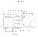
FIG. 14 is an operation explanatory view relating to an operation to carry out a commodity; -
FIG. 15 is an operation explanatory view relating to an operation to carry out a commodity; -
FIG. 16 is an operation explanatory view relating to an operation to carry out a commodity; -
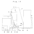
FIG. 17 is an operation explanatory view relating to an operation to carry out a commodity; -
FIG. 18 is an operation explanatory view relating to an operation to carry out a commodity; -
FIG. 19 is an operation explanatory view relating to an operation to carry out a commodity; -
FIG. 20 is an operation explanatory view relating to an operation to carry out a commodity; -
FIG. 21 is an operation explanatory view relating to an operation to carry out a commodity; -
FIG. 22 is an operation explanatory view relating to an operation to carry out a commodity; -
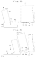
FIG. 23 is a side surface cross-section of a bucket unit and a commodity storage column that illustrates a second embodiment of the present invention; -
FIG. 24 is an operation explanatory view relating to an operation to carry out a commodity; -
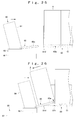
FIG. 25 is a side surface cross-section of a bucket unit and a commodity storage column that illustrates a third embodiment of the present invention; -
FIG. 26 is an operation explanatory view relating to an operation to carry out a commodity; -
FIG. 27 is a side surface cross-section of a bucket unit and a commodity storage column that illustrates a fourth embodiment of the present invention; and -
FIG. 28 is an operation explanatory view relating to an operation to carry out a commodity. -
FIG. 1 to FIG. 22 illustrate the first embodiment of the present invention. - An automatic vending machine that includes this commodity carrying out device comprises an automatic vending machine
main unit 10 that has an opening at the front, anexternal door 20 provided in an openable and closable condition at one end side in the width direction of the opening of the automatic vending machinemain unit 10, and anoperation door 30 provided in an openable and closable condition at the other end side in the width direction of the opening of the automatic vending machinemain unit 10. - The automatic vending machine
main unit 10 is provided with acommodity storage chamber 12 for storing commodities A for sale and anequipment storage chamber 13 for storing equipment relating to selling operations. This is achieved by partitioning the inside of the automatic vending machinemain unit 10 in the width direction with a heatinsulating partition wall 11. The interior surface of thecommodity storage chamber 12 is covered with a heat insulating material. At the lower part of theequipment storage chamber 13 is provided acommodity outlet portion 14 to which a commodity A to be sold is carried. An opening 15 that connects thecommodity outlet portion 14 and thecommodity storage chamber 12 is provided in thepartition wall 11. - The
external door 20 is rotatably supported at one end side in the width direction of the automatic vending machinemain unit 10 and is arranged to open and close the front of thecommodity storage chamber 12. Theexternal door 20 comprises atransparent plate 21 comprising glass or a synthetic resin or the like and aframe member 22 provided around the perimeter of thetransparent plate 21. The interior of thecommodity storage chamber 12 can be visually recognized from outside theexternal door 20. - The
operation door 30 is rotatably supported at the other end side in the width direction of the automatic vending machinemain unit 10 and is arranged to open and close the front of theequipment storage chamber 13. At the front of theoperation door 30 are provided acoin insertion slot 31, acoin return lever 32, amoney amount indicator 33, abanknote insertion slot 34, acommodity selection portion 35, acoin return port 36, and acommodity outlet port 37. - In the
commodity storage chamber 12 are provided a plurality ofcommodity storage columns 50 that are disposed in alignment in the width direction with a plurality of vertically spacedshelves 40, respectively, abucket unit 60 as a commodity carrying out device for carrying a commodity A stored in acommodity storage column 50 to thecommodity outlet portion 14, and aunit moving device 70. Thecommodity storage chamber 12 is also configured so as to be cooled or heated by a cooler and an electric heater that are not shown. At the lower part of thecommodity storage chamber 12 is provided an equipment chamber for housing unshown refrigerating devices such as a compressor and a radiator. - The space dimensions of each of the vertically aligned
shelves 40 are slightly greater than the height dimensions of a commodity A to be stored. This prevents erroneous storage of a commodity A that has large height dimensions that are different to the height dimensions of a commodity A that is intended to be stored. Eachshelf 40 is formed so that the dimensions thereof in the front-to-rear direction are smaller than the dimensions in the front-to-rear direction of thecommodity storage column 50. Further, to secure an operating space for receiving a commodity A into thebucket unit 60 from thecommodity storage column 50, the front end of eachshelf 40 is positioned further to the rear side than the front end of thecommodity storage column 50. - Each
commodity storage column 50 is provided with acommodity passage 50a extending in the front-to-rear direction that is formed by abase plate 51 and aside plate 52. Vertically long commodities A such as canned beverages, bottled beverages, or PET bottles can be stored in thecommodity passage 50a in a condition in which they are aligned in the front-to-rear direction. At the front end side of thebase plate 51, acommodity locking portion 51a that is formed to extend vertically is provided for restricting movement of a commodity A in the frontward direction. Further, on the front end side of thebase plate 51 is provided anotch portion 51b that enables movement of a fork member, described later, of thebucket unit 60 in the vertical direction. - Each
commodity storage column 50 comprises an ejectingplate 53 which is provided in a moveable condition in the front-to-rear direction with respect to thecommodity passage 50a and which is urged frontward by an unshown urging member such as a power spring. By storing a commodity A at the front side of the ejectingplate 53, the commodity A receives an urging force that urges the commodity A forward. Further, the ejectingplate 53 is provided with anotch portion 53a that enables movement of a fork member, described later, of thebucket unit 60 in the vertical direction when the ejectingplate 53 is positioned at the front end side of thecommodity passage 50a. - In each
commodity storage column 50, agate plate 54 that opens and closes the front end side of thecommodity passage 50a is connected in a vertically rotatable condition to the front end side of theside plate 52. Thegate plate 54 is arranged so as to block off thecommodity passage 50a in a posture in which it extends diagonally upward from theside plate 52. Thegate plate 54 is urged in a direction that blocks off thecommodity passage 50a by an urging member such as a coiled spring. Further, thegate plate 54 is arranged to open thecommodity passage 50a by rotating upward against the urging force of the urging member through contact of a gate release portion, described later, provided on thebucket unit 60 side against the bottom surface of thegate plate 54. Aguide portion 52a for guiding the gate release portion in the front-to-rear direction is also provided on thecommodity passage 50a side of theside plate 52 on which thegate plate 54 is supported. - The
bucket unit 60 comprises aunit base 61 that is connected with aunit moving device 70, abucket base 62 that is moveable in the front-to-rear direction with respect to theunit base 61, a rotatingmember 63 that is rotatably supported by thebucket base 62 with the vertical direction as the central axis, abucket 64 that is supported by the rotatingmember 63 and is provided to support a side surface of a commodity A that is carried out, afork member 65 that is rotatably supported in the vertical direction by the lower end of thebucket 64 and which supports the bottom surface of a commodity A that is carried out, arotation restricting member 66 for restricting rotation of thefork member 65, acommodity detecting plate 67 for detecting the existence or non-existence of a commodity A within thebucket 64, and arestriction releasing member 68 for releasing the rotation restriction of thefork member 65 by therotation restricting member 66. - The
unit base 61 has anelectric motor 61a as a motive power that moves thebucket base 62 in the front-to-rear direction and also rotates thebucket 64, aguide groove 61b for guiding thebucket base 62 in the front-to-rear direction, aprotrusion 61c that imparts a force that rotates the rotatingmember 63 to thecommodity outlet portion 14 side upon movement of thebucket base 62 to the front, a pair of width direction rails 61d for regulating movement of thefork member 65 in the width direction to guide thefork member 65 in the front-to-rear direction, and acommodity detecting sensor 61e such as a microswitch that is turned on/off by thecommodity detecting plate 67. - The two ends on the left and right of the bottom surface side and the upper and lower sides of one end in the width direction of the
bucket base 62 are formed so as to engage with theguide groove 61b that is provided in theunit base 61 so that thebucket base 62 is movable along theguide groove 61b. Agroove 62a extending in the width direction is also provided on the bottom surface of thebucket base 62, and alink member 69 having one end connected to theelectric motor 61a is arranged so that the other end side thereof engages with thegroove 62a. More specifically, when thelink member 69 is rotated by theelectric motor 61a, thebucket base 62 is moved in the front-to-rear direction along theguide groove 61b by the movement of the other end side of thelink member 69. Anabutting portion 62b formed to have a curved surface shape is provided in thebucket base 62. The surface of thebucket 64 on the opposite side of the commodity receiving surface contacts against the abuttingportion 62b. Agate release portion 62c that extends rearward from a position below the abuttingportion 62b is also provided in thebucket base 62. By rearward movement of thebucket base 62, thegate release portion 62c presses thegate plate 54 upward to open the front end side of thecommodity passage 50a. - The rotating
member 63 is connected to thebucket 64 in a condition in which thebucket 64 is rotatable backwards and forwards. Further, an end in the width direction of the rotatingmember 63 is rotatably connected to thebucket base 62. The rotatingmember 63 is urged by an unshown urging member so that the commodity receiving surface of thebucket 64 faces rearward (towards the commodity storage column side). More specifically, the rotatingmember 63 moves in the front-to-rear direction together with thebucket base 62 in a state in which the commodity receiving surface of thebucket 64 faces rearward. Furthermore, when thebucket base 62 moves to the front end side of theunit base 61, the rotatingmember 63 is pushed by theprotrusion 61c arranged in theunit base 61 so as to extend rearward. As a result, the orientation of the rotatingmember 63 changes by 90° to thecommodity outlet portion 14 side. - The
bucket 64 is formed in a semi-cylindrical, curved surface shape in which a concave side serves as a commodity receiving surface. In thebucket 64, the lower end side is rotatably connected to the rotatingmember 63, and a surface on a side opposite the commodity receiving surface is supported by the abuttingportion 62b of thebucket base 62 so that the commodity receiving surface faces diagonally upward. The angle of inclination of thebucket 64 is arranged so as to be changed in accordance with the shape of the abuttingportion 62b of thebucket base 62 and the shape of thebucket 64 against which the abuttingportion 62b abuts. According to the present embodiment, when thebucket 64 rotates to thecommodity outlet portion 14 side, the angle of inclination of thebucket 64 at the start of rotation is set to be less than when receiving a commodity A. Thereafter, when thebucket 64 faces completely to thecommodity outlet portion 14 side, the angle of inclination is set to be larger than when receiving a commodity A. An opening for attaching thecommodity detecting plate 67 is provided at the center in the width direction of thebucket 64, in a condition in which the opening extends in the vertical direction. - The base end side of the
fork member 65 is connected to the lower end side of thebucket 64 in a condition in which thefork member 65 is rotatable in the vertical direction. Thefork member 65 is provided with a plurality ofcommodity supporting portions 65a that are arranged with a space between eachcommodity supporting portion 65a. On the under surface of thefork member 65 are provided a pair ofgrooves 65b for moving thefork member 65 along the pair ofwidth direction rails 61d provided in theunit base 61 that restrict movement in the width direction of thefork member 65. The upper surface of thefork member 65 is inclined in a normal state from the base end side towards the front end side. On the bottom surface on the base end side of thefork member 65 is provided acontact surface 65c that contacts with the top surface of theunit base 61. The angle of the top surface of thefork member 65 can be changed depending on the shape of the top surface of theunit base 61. More specifically, the top surface of theunit base 61 against which thecontact surface 65c contacts is formed to be low at the rear end side so that when thebucket base 62 is positioned at the rear end side, the angle of inclination of the top surface of thefork member 65 is small, and when thebucket base 62 is disposed at a position other than the rear end side, the angle of inclination of the top surface of thefork member 65 is greater than when thebucket base 62 is positioned at the rear end side. - The
rotation restricting member 66 is arranged to be moveable in the vertical direction at a lower part of the surface on the opposite side to the commodity receiving surface of thebucket 64, and is urged toward the bottom side by an unshown urging member. Therotation restricting member 66 contacts against the end on the base end side of thefork member 65 in a state in which therotation restricting member 66 is positioned on the lower side to thereby restrict downward rotation of thefork member 65. Therotation restricting member 66 is arranged so as to release the restriction on downward rotation of thefork member 65 by moving upward. Therotation restricting member 66 is arranged so as to be pressed upward by therestriction releasing member 68. - The
commodity detecting plate 67 extends in the vertical direction over the commodity receiving surface side of thebucket 64, and the top end side thereof is rotatably supported by thebucket 64. Similarly to thebucket 64, thecommodity detecting plate 67 is formed in a curved surface shape so that a center portion in the width direction of the commodity receiving surface curves inward vertically so that a commodity A that is received in thebucket 64 is moved to the center portion side. The lower end side of thecommodity detecting plate 67 is urged in a direction away from the commodity receiving surface of thebucket 64 by an unshown urging member so as to rotate when a commodity A is received. Acommodity detecting sensor 61e provided in theunit base 61 is arranged so as to be turned on/off by the top end of thecommodity detecting plate 67 in a state in which the commodity receiving surface of thebucket 64 is facing thecommodity outlet portion 14 side. According to the present embodiment, in a state in which the commodity receiving surface of thebucket 64 is facing thecommodity outlet portion 14 side, when thebucket 64 contains a commodity A, thecommodity detecting sensor 61e turns off, and when thebucket 64 does not contain a commodity A, thecommodity detecting sensor 61e turns on. Anabutting portion 67a against which therotation restricting member 66 that moves upward contacts is provided in a projecting condition on the surface of the side opposite the commodity receiving surface of thecommodity detecting plate 67. When therotation restricting member 66 contacts against the abuttingportion 67a in a state in which a commodity A is in thebucket 64, the lower end side of thecommodity detecting plate 67 moves towards the commodity A to push out the commodity A from thebucket 64. - The
restriction releasing member 68 is provided in a condition in which it is linearly moveable in a diagonally upward direction on thecommodity outlet portion 14 side of theunit base 61. Therestriction releasing member 68 is arranged so as to push therotation restricting member 66 upward when therestriction releasing member 68 is operated in a state in which the commodity receiving surface of thebucket 64 is facing thecommodity outlet portion 14 side. Therestriction releasing member 68 is arranged so as to be operated by contact with an operatingportion 16 that is provided adjacent to theopening 15 that communicates with thecommodity outlet portion 14 upon the operatingportion 16 moving horizontally to thecommodity outlet portion 14 side of theunit base 61. Further, therestriction releasing member 68 has anabutting portion 68a that extends to thebucket base 62 side. Therestriction releasing member 68 is arranged so as to be lowered downward by contact of thebucket base 62 with the abuttingportion 68a when thebucket base 62 moves rearward. - The
unit moving device 70 is provided at the front side of thecommodity storage chamber 12. Theunit moving device 70 comprises awidthwise movement mechanism 71 for moving thebucket unit 60 in the width direction and avertical movement mechanism 72 for moving thebucket unit 60 in the vertical direction. Thewidthwise movement mechanism 71 and thevertical movement mechanism 72 are respectively constituted by an unshown mechanism that converts rotational motion into linear motion, such as a belt and pulley, a chain and sprocket, or a feed screw mechanism. Thewidthwise movement mechanism 71 and thevertical movement mechanism 72 are respectively arranged to be driven by an electric motor so as to move thebucket unit 60 in the width direction and the vertical direction. - In the automatic vending machine configured as described above, when a user inserted a predetermined amount of money into the
coin insertion slot 31 or thebanknote insertion slot 34 and selects a predetermined commodity A at thecommodity selection portion 35, first, thebucket unit 60 that is positioned at a predetermined standby position moves using theunit moving device 70 to the front end side of acommodity storage column 50 in which the selected commodity A is stored. Next, as shown inFIG. 12 , theelectric motor 61a is driven to lower thecommodity supporting portion 65a of thefork member 65 downward while moving thebucket base 62 rearward with respect to theunit base 61 so that, as shown inFIG. 13 , thecommodity supporting portion 65a is inserted to an area below the commodity A positioned at the front end side of thecommodity storage column 50. At this time, as shown inFIG. 14 , thegate release portion 62c of thebucket base 62 contacts the bottom surface of thegate plate 54 of thecommodity storage column 50, thegate plate 54 is rotated upward by the rearward movement of thebucket base 62, to thereby open the front end side of thecommodity passage 50a of thecommodity storage column 50. Further, positioning in the width direction of thebucket unit 60 with respect to thecommodity storage column 50 is carried out by one end side in the width direction of thegate release portion 62c contacting with thegate plate 54 and the other end side in the width direction of thegate release portion 62c contacting with theguide portion 52a. Next, as shown inFIG. 15 , thebucket unit 60 is moved upward by theunit moving device 70 so that the commodity A is lifted by thefork member 65 to receive the commodity A inside thebucket 64. At this time, since the top surface of thefork member 65 forms a downward slope from the front edge side to the base end side thereof, as shown inFIG. 16 , the commodity A that is lifted upward tilts forward so that it moves forward and is received inside thebucket 64. As shown inFIG. 17 , thebucket unit 60 that receives the commodity A moves thebucket base 62 forward with respect to theunit base 61 and, as shown inFIG. 18 , raises thecommodity supporting portion 65a of thefork member 65 upward to incline the commodity A to thebucket 64 side. Thereafter, when thebucket base 62 is moved further forward, as shown inFIG. 19 , thebucket 64 rotates to thecommodity outlet portion 14 side. At this time, when thebucket base 62 moves forward with respect to theunit base 61, the rotatingmember 63 contacts against theprotrusion 61c of theunit base 61 and changes orientation by 90° to thecommodity outlet portion 14 side, and as a result thebucket 64 rotates towards thecommodity outlet portion 14. Further, when rotating thebucket 64 to thecommodity outlet portion 14 side, by rotating thebucket 64 while thebucket 64 contacts against the abuttingportion 62b, the angle of inclination of thebucket 64 at the front end of the automatic vending machinemain unit 10 is made small and the angle of inclination of thebucket 64 in a state in which thebucket 64 faces thecommodity outlet portion 14 side is made large. Next, in a state in which thebucket 64 faces thecommodity outlet portion 14 side, as shown inFIG. 20 , thebucket unit 60 containing the commodity A is moved in the vertical direction and width direction by theunit moving device 70 to move to the commodity carrying out position. Subsequently, by movement in the width direction of theunit moving device 70, as shown inFIG. 21 , therestriction releasing member 68 contacts against the operatingportion 16 provided adjacent to theopening 15 of thecommodity outlet portion 14 and moves diagonally upward to thereby move therotation restricting member 66 upward. This movement releases the restriction on rotation of thefork member 65 so that thefork member 65 rotates downward and the received commodity A is carried out in a diagonally downward direction. Further, when therotation restricting member 66 moves upward, as shown inFIG. 22 , therotation restricting member 66 contacts against the abuttingportion 67a of thecommodity detecting plate 67 to cause thecommodity detecting plate 67 to rotate. As a result, the commodity A in thebucket 64 is pushed out in a diagonally upward direction so that the commodity A is reliably carried out to thecommodity outlet portion 14. Thebucket unit 60 from which the commodity A has been carried out is then moved to the predetermined standby position by theunit moving device 70 to complete the operation. - Thus, according to the commodity carrying out device of the present embodiment, a commodity A that is located at the front end side of the
commodity storage column 50 is tilted forward and moved into thebucket 64. As a result, when moving a vertically-long shaped commodity A in an upright state into thebucket 64, the commodity A can be moved without the commodity A toppling backwards. Therefore, the commodity A can be reliably moved into thebucket 64. - Further, a commodity A that is located at the front end side of the
commodity storage column 50 is tilted forward and moved inside thebucket 64 by means of afork member 65 for supporting the bottom surface of the commodity A that is arranged on thebucket 64 side so that the top surface thereof forms a downward slope from thecommodity storage column 50 side towards thebucket 64 side, anotch portion 51b which is provided at the front end side of thecommodity storage column 50 and through which acommodity supporting portion 65a of thefork member 65 can pass, and aunit moving device 70. It is thus possible to tilt the commodity A to move the commodity A inside thebucket 64 by moving thebucket unit 60 upward from below. Therefore, production costs can be reduced since a complicated mechanism is not necessary. - The commodity carrying out device of the present embodiment also comprises a
gate plate 54 which is provided in a vertically rotatable condition at the front end side of thecommodity storage column 50 and which opens and closes the front end side of thecommodity passage 50a, agate release portion 62c which is arranged so as to extend to thecommodity storage column 50 side in thebucket base 62 and which contacts against thegate plate 54 upon movement to thecommodity storage column 50 side of thebucket base 62 to rotate thegate plate 54 in a direction that opens the front end side of thecommodity passage 50a, and aguide portion 52a which is provided on thecommodity storage column 50 side and which guides thegate release portion 62c in the front-to-rear direction when thegate release portion 62c rotates thegate plate 54 to open the front end side of thecommodity passage 50a. It is thereby possible to open thecommodity passage 50a by movement in the front-to-rear direction of thebucket base 62 and also restrict displacement in the width direction of thebucket unit 60 with respect to thecommodity storage column 50 and guide thebucket unit 60 in the front-to-rear direction. Consequently, costs can be decreased since a motive power is not separately required to open thecommodity passage 50a, and positioning of thebucket unit 60 with respect to thecommodity storage column 50 can also be easily performed. - The
fork member 65 is arranged to rotate in a direction that forms a downward slope towards thebucket 64 side when thebucket 64 is moved forward. Since it is thereby possible to tip a commodity A that is received inside thebucket 64 back further to thebucket 64 side, the commodity A can be received in a more stable state inside thebucket 64. - Further, by means of a pair of
rails 61d provided on theunit base 61 and a pair ofgrooves 65b provided on thefork member 65, movement in the width direction of thefork member 65 is restricted to guide thefork member 65 in the front-to-rear direction. Since it is thereby possible to reliably position thefork member 65 in the width direction with respect to thecommodity storage column 50, the length dimensions of thecommodity supporting portion 65a of thefork member 65 can be increased to accommodate a commodity A that has large outer diameter dimensions. - The
notch portion 53a that permits movement in the vertical direction of thecommodity supporting portion 65a of thefork member 65 is provided in the ejectingplate 53. It is thereby possible to prevent contact with the ejectingplate 53 by thecommodity supporting portion 65a of thefork member 65 when the ejectingplate 53 is positioned at the front end side of thecommodity passage 50a, and thus it is also possible to accommodate carrying out of a commodity A with small outer diameter dimensions. - The commodity carrying out device of the present embodiment also comprises a
commodity detecting plate 67 and acommodity detecting sensor 61e for detecting the existence or non-existence of a commodity A inside thebucket 64. It is therefore possible to detect when a commodity A is sold out or when a fault occurs in an operation to carry out a commodity A. Thus, when a commodity A of a predeterminedcommodity storage column 50 is sold out the commodity A of a differentcommodity storage column 50 can be carried out, and in the case of a failure to receive a commodity A in thebucket 64, the carrying out operation is performed again so that the commodity A can be definitely sold. - Each
shelf 40 is disposed so that the dimensions of a space between verticallyadjacent shelves 40 are substantially the same as the height dimensions of the commodity A. A space necessary for operations to receive a commodity A in thebucket 64 is provided at the front of eachshelf 40. It is thereby possible to prevent defective carrying out due to erroneous storage of a commodity that has larger height dimensions than the height dimensions of the commodity A that is intended to be stored. -
FIG. 23 and FIG. 24 are views that illustrate a second embodiment of the present invention. In the figures, components that are the same as those of the above described embodiment are denoted by the same reference symbols. - In this automatic vending machine, the
fork member 65 is provided so that the top surface of thecommodity supporting portion 65a is rotatable from a state in which the top surface lies in a substantially horizontal plane to a direction in which the top surface forms a downward slope towards thebucket 64 side. Further, in thenotch portion 51b of thebase plate 51 of thecommodity storage column 50 is provided anabutting portion 51c that contacts against thefork member 65 to rotate thefork member 65 when thebucket unit 60 is moved downward. - In the automatic vending machine arranged as described above, when receiving a commodity A located at the front end side of the
commodity storage column 50 into thebucket 64, thebucket unit 60 is moved rearward to insert thecommodity supporting portion 65a of thefork member 65 into thenotch portion 51b of thecommodity storage column 50, and thebucket unit 60 is then moved downward. As a result, the bottom surface of thefork member 65 contacts against the abuttingportion 51c to thereby rotate thefork member 65, and the top surface of thefork member 65 inclines to thebucket 64 side while lifting the commodity A. Thus, the commodity A is tilted to thebucket 64 side and moves to thebucket 64 side to thereby receive the commodity A in thebucket 64. - Thus, according to the commodity carrying out device of the present embodiment, a commodity A positioned at the front end side of a
commodity storage column 50 is tilted forward and moved into thebucket 64 by means of thefork member 65 provided in a condition in which the angle of inclination of the top surface of thecommodity supporting portion 65a is changeable from a state in which the top surface lies in a substantially horizontal plane to a direction in which the top surface forms a downward slope towards thebucket 64 side, and the abuttingportion 51c that causes the top surface of thecommodity supporting portion 65a to incline to thebucket 64 side by contacting against thefork member 65 from below when thebucket unit 60 is moved downward. As a result, the commodity A can be tilted forward and moved into thebucket 64 by moving thebucket unit 60 downward. Therefore, production costs can be reduced since a complicated mechanism is not necessary. -
FIG. 25 and FIG. 26 are views that illustrate a third embodiment of the present invention. In the figures, components that are the same as those of the above described embodiments are denoted by the same reference symbols. - In this automatic vending machine, the top surface of the
commodity supporting portion 65a of thefork member 65 is provided in a condition in which the top surface can be rotated from a state in which the top surface forms a slightly downward slope to thebucket 64 side with respect to the horizontal plane to a direction in which the angle of inclination to thebucket 64 side increases. Further, an abuttingportion 51d is provided in thenotch portion 51b of thebase plate 51 of thecommodity storage column 50. The abuttingportion 51d contacts against the bottom surface of thefork member 65 to thereby cause thefork member 65 to rotate when thebucket unit 60 moves horizontally to thecommodity storage column 50 side. - In the automatic vending machine arranged as described above, when receiving a commodity A located at the front end side of the
commodity storage column 50 into thebucket 64, thebucket unit 60 is moved rearward to insert the tip of thecommodity supporting portion 65a of thefork member 65 into thenotch portion 51b of thecommodity storage column 50. As a result, the bottom surface of thefork member 65 contacts against the abuttingportion 51d to thereby rotate thefork member 65, and the top surface of thefork member 65 inclines further to thebucket 64 side while lifting the commodity A. Thus, the commodity A is tilted to thebucket 64 side and moves to thebucket 64 side to thereby receive the commodity A in thebucket 64. - Thus, according to the commodity carrying out device of the present embodiment, a commodity A positioned at the front end side of the
commodity storage column 50 is tilted forward and moved into thebucket 64 by means of thefork member 65 provided in a condition in which the angle of inclination thereof is changeable from a state in which the top surface of thecommodity supporting portion 65a forms a slightly downward slope to thebucket 64 side with respect to the horizontal plane to a direction in which the angle of inclination to thebucket 64 side increases, and an abuttingportion 51d that causes the top surface of thecommodity supporting portion 65a to incline to thebucket 64 side by contacting against thefork member 65 from below when thebucket unit 60 is moved towards thecommodity storage column 50 side. As a result, the commodity A can be tilted forward and moved into thebucket 64 by moving thebucket unit 60 to thecommodity storage column 50 side. Therefore, production costs can be reduced since a complicated mechanism is not necessary. -
FIG. 27 and FIG. 28 are views that illustrate a fourth embodiment of the present invention. In the figures, components that are the same as those of the above described embodiments are denoted by the same reference symbols. - This automatic vending machine is arranged so that the top surface of the
commodity supporting portion 65a of thefork member 65 forms a downward slope towards thebucket 64 side. Further, at the front end side of thebase plate 51 of thecommodity storage column 50 is provided amovable portion 55 that is rotatable from a state in which the top surface thereof lies in a substantially horizontal plane to a direction in which the top surface forms a downward slope towards thebucket 64 side. Themovable portion 55 is arranged so as to be rotated by an unshown electric motor or a link mechanism or the like. - In the automatic vending machine arranged as described above, when receiving a commodity A located at the front end side of the
commodity storage column 50 into thebucket 64, thebucket unit 60 is moved to dispose the tip of thecommodity supporting portion 65a of thefork member 65 below thecommodity storage column 50, and themovable portion 55 is rotated to incline the top surface thereof to thebucket 64 side. Thereby, the commodity A on themovable portion 55 is tilted to thebucket 64 side and moves to thebucket 64 side so that the commodity A is received in thebucket 64. - Thus, according to the commodity carrying out device of the present embodiment, a commodity A positioned at the front end side of the
commodity storage column 50 is tilted forward and moved into thebucket 64 by means of themovable portion 55 provided at the front end side of thebase plate 51 of thecommodity storage column 50 in a condition in which an angle of inclination thereof is changeable from a state in which the top surface lies in a substantially horizontal plane to a state in which the top surface forms a downward slope to thebucket 64 side. As a result, the commodity A can be tilted forward and moved into thebucket 64 by rotating themovable portion 55 downward. Therefore, production costs can be reduced since a complicated mechanism is not necessary. - According to the above described embodiment, a configuration was illustrated in which the
commodity detecting sensor 61e that is turned on/off by thecommodity detecting plate 67 is provided in theunit base 61. However, even when thecommodity detecting sensor 61e is provided in thebucket 64, thecommodity detecting sensor 61e can similarly detect when a commodity A is sold out or when a fault occurs during an operation to carry out a commodity A. When the commodity A of a predeterminedcommodity storage column 50 is sold out, the commodity A of a differentcommodity storage column 50 can be carried out, and in the case of a failure to receive a commodity A in thebucket 64, the carrying out operation is performed again so that the commodity A can be definitely sold. - The embodiments described in the present specification are exemplary embodiments of the present invention and are not intended to limit the present invention. It should be understood that the scope of this invention is defined by the attached claims, and all modifications within the meaning of those claims are included in the present invention.
Claims (11)
- A commodity carrying out device, comprising:a plurality of commodity storage columns (50) aligned in a vertical direction and a width direction with respect to each other for storing commodities (A) side by side in a front-to-rear direction;a bucket (64) for receiving a commodity (A) to be carried out;a bucket moving mechanism (70) for moving the bucket (64) to a front side of an arbitrary commodity storage column (50) and moving the bucket (64) that receives the commodity (A) to a predetermined commodity carrying out position; anda commodity reception mechanism for tilting a commodity (A) positioned at a front end side of the commodity storage column (50) to a bucket (64) side to move the commodity (A) into the bucket (64).
- The commodity carrying out device according to claim 1, wherein
the commodity reception mechanism includes: a commodity supporting member (65) for supporting a bottom surface of a commodity (A), that is provided on the bucket (64) side so that a top surface thereof forms a downward slope from the commodity storage column (50) side to the bucket (64) side; a notch (51b) for allowing the commodity supporting member (65) to pass therethrough in a vertical direction, that is provided at the front end side of the commodity storage column (50); and a bucket moving mechanism (70) for moving the bucket (64) in the vertical direction. - The commodity carrying out device according to claim 1, wherein
the commodity reception mechanism includes: a commodity supporting member (65) for supporting a bottom surface of a commodity (A), that is provided in the bucket (64) in a condition in which an angle of inclination thereof is changeable from a state in which a top surface thereof lies in a substantially horizontal plane to a direction in which the top surface forms a downward slope towards the bucket (64) side; an abutting portion (51c) that is provided at the front end side of the commodity storage column (50), for causing the top surface of the commodity supporting member (65) to incline to the bucket (64) side by contacting against the commodity supporting member (65) from below when the bucket (64) is moved downward; and a bucket moving mechanism (70) for moving the bucket (64) in the vertical direction. - The commodity carrying out device according to claim 1, wherein
the commodity reception mechanism includes: a commodity supporting member (65) for supporting a bottom surface of a commodity (A), that is provided in the bucket (64) in a condition in which an angle of inclination is changeable from a state in which a top surface thereof forms a slightly downward slope to the bucket (64) side with respect to the horizontal plane to a direction in which an angle of the downward slope to the bucket (64) side increase; an abutting portion (51d) provided at a front end side of the commodity storage column (50) for causing the top surface of the commodity supporting member (65) to incline to the bucket (64) side by contacting against the bottom surface of the commodity supporting member (65) that moves to the commodity storage column (50) side; and a bucket moving mechanism (61, 62) for moving the bucket (64) in the front-to-rear direction. - The commodity carrying out device according to claim 1, wherein:the commodity reception mechanism includes a movable portion (55) provided at the front end side at the bottom of the commodity storage column (50) in a condition in which an angle of inclination thereof can be changed from a state in which a top surface thereof is substantially horizontal to a state in which the top surface forms a downward slope towards the bucket (64) side.
- The commodity carrying out device according to any one of claims 1 to 5, further comprising:a gate member (54) for opening and closing a front end side of a commodity passage (50a), that is provided in a vertically rotatable condition at the front end side of the commodity storage column (50);a gate release portion (62c) provided on the bucket (64) side for contacting against the gate member (54) accompanying movement of the bucket (64) to the commodity storage column (50) side, to thereby cause the gate member (54) to rotate in a direction that opens the front end side of the commodity passage (50a); anda guide portion (52a) provided on the commodity storage column (50) side for guiding the gate release portion (62c) in the front-to-rear direction when causing the gate member (54) to rotate to open the front end side of the commodity passage (50a).
- The commodity carrying out device according to any one of claims 2 to 4, wherein:an angle of a downward slope to the bucket (64) side of the top surface of the commodity supporting member (65) increases by moving the bucket (64) forward.
- The commodity carrying out device according to any one of claims 2 to 4, wherein:the commodity reception mechanism has a positioning mechanism (61d, 65b) for guiding the commodity supporting member (65) in the front-to-rear direction to restricts movement of the commodity supporting member (65) in the width direction.
- The commodity carrying out device according to any one of claims 2 to 4, further comprising:an ejecting member (53) provided in a condition in which the ejecting member (53) can move through a commodity passage (50a) of the commodity storage column (50), for causing commodities (A) that are arranged side by side in the commodity passage (50a) to move forward from a rear surface side, wherein;the ejecting member (53) is provided with a notch (53a) that allows movement in the vertical direction of the commodity supporting member (65).
- The commodity carrying out device according to any one of claims 1 to 5, wherein:a commodity detection mechanism (61e, 67) that detects the existence or non-existence of a commodity (A) is arranged in the bucket (64).
- The commodity carrying out device according to any one of claims 1 to 5, further comprising:a plurality of shelves (40) that are aligned with respect to each other in the vertical direction and on which a plurality of commodity storage columns (50) are mountable in the width direction, wherein;each shelf (40) is disposed so that a space between vertically adjacent shelves (40) is substantially the same as height dimensions of a commodity; anda space necessary for operations for receiving a commodity A in the bucket (64) is provided at the front of each shelf (40).
Priority Applications (2)
| Application Number | Priority Date | Filing Date | Title |
|---|---|---|---|
| EP11175385.1A EP2383708B1 (en) | 2007-05-16 | 2008-05-12 | Commodity carrying out device |
| EP11178787.5A EP2390849B1 (en) | 2007-05-16 | 2008-05-12 | Commodity carrying out device |
Applications Claiming Priority (1)
| Application Number | Priority Date | Filing Date | Title |
|---|---|---|---|
| JP2007130300 | 2007-05-16 |
Related Child Applications (2)
| Application Number | Title | Priority Date | Filing Date |
|---|---|---|---|
| EP11178787.5A Division EP2390849B1 (en) | 2007-05-16 | 2008-05-12 | Commodity carrying out device |
| EP11175385.1A Division EP2383708B1 (en) | 2007-05-16 | 2008-05-12 | Commodity carrying out device |
Publications (3)
| Publication Number | Publication Date |
|---|---|
| EP1993078A2 true EP1993078A2 (en) | 2008-11-19 |
| EP1993078A3 EP1993078A3 (en) | 2009-02-11 |
| EP1993078B1 EP1993078B1 (en) | 2011-07-27 |
Family
ID=39712639
Family Applications (3)
| Application Number | Title | Priority Date | Filing Date |
|---|---|---|---|
| EP11175385.1A Expired - Fee Related EP2383708B1 (en) | 2007-05-16 | 2008-05-12 | Commodity carrying out device |
| EP08156050A Active EP1993078B1 (en) | 2007-05-16 | 2008-05-12 | Commodity carrying out device |
| EP11178787.5A Expired - Fee Related EP2390849B1 (en) | 2007-05-16 | 2008-05-12 | Commodity carrying out device |
Family Applications Before (1)
| Application Number | Title | Priority Date | Filing Date |
|---|---|---|---|
| EP11175385.1A Expired - Fee Related EP2383708B1 (en) | 2007-05-16 | 2008-05-12 | Commodity carrying out device |
Family Applications After (1)
| Application Number | Title | Priority Date | Filing Date |
|---|---|---|---|
| EP11178787.5A Expired - Fee Related EP2390849B1 (en) | 2007-05-16 | 2008-05-12 | Commodity carrying out device |
Country Status (4)
| Country | Link |
|---|---|
| US (1) | US20080283545A1 (en) |
| EP (3) | EP2383708B1 (en) |
| JP (1) | JP5222446B2 (en) |
| CN (1) | CN101308591B (en) |
Cited By (8)
| Publication number | Priority date | Publication date | Assignee | Title |
|---|---|---|---|---|
| ITTO20080899A1 (en) * | 2008-12-04 | 2010-06-05 | N&W Global Vending Spa | AUTOMATIC DISTRIBUTOR FOR THE DISTRIBUTION OF PRODUCTS |
| WO2011054931A3 (en) * | 2009-11-05 | 2011-06-30 | Meteor Ag | Food vending machine and identification device for identifying edible products in a food vending machine |
| EP2693412A1 (en) * | 2011-03-30 | 2014-02-05 | Sanden Corporation | Vending machine |
| ITVI20130214A1 (en) * | 2013-08-09 | 2015-02-10 | Idea Srl | AUTOMATED WAREHOUSE |
| EP2587460A4 (en) * | 2010-06-25 | 2015-05-13 | Fuji Electric Co Ltd | Automatic vending machine |
| EP2587459A4 (en) * | 2010-06-25 | 2015-05-13 | Fuji Electric Co Ltd | Product stowing device for automatic vending machine |
| EP2876614A1 (en) * | 2013-11-25 | 2015-05-27 | Wincor Nixdorf International GmbH | Fully automatic package station |
| WO2016139381A1 (en) * | 2015-03-02 | 2016-09-09 | Jofemar, S. A. | Dispensing machine |
Families Citing this family (11)
| Publication number | Priority date | Publication date | Assignee | Title |
|---|---|---|---|---|
| US20110186591A1 (en) * | 2008-07-18 | 2011-08-04 | Steve Pfister | On demand consumable product heating and/or cooling dispenser |
| DE102010000595A1 (en) * | 2009-02-27 | 2010-09-02 | Gühring Ohg | Modular machine tool |
| JP5853526B2 (en) * | 2011-03-16 | 2016-02-09 | 富士電機株式会社 | vending machine |
| EP2568451B1 (en) | 2011-09-12 | 2014-05-07 | Astore, SIA | Means for conveying articles from a shelf of an automatic store or vending machine to a carriage and/or from the carriage to the shelf |
| KR20150063361A (en) * | 2012-08-24 | 2015-06-09 | 수퍼쿨러 주식회사 | Beverage vending machine and method for controlling temperature of vending machine |
| WO2015019645A1 (en) * | 2013-08-09 | 2015-02-12 | 富士電機株式会社 | Product storage device |
| CN105574991B (en) * | 2016-01-26 | 2018-11-13 | 橙果信息技术有限公司 | Automatic vending machine goods taking device |
| MX2019008336A (en) * | 2017-01-12 | 2019-10-21 | Crane Merchandising Sys Inc | Enhanced vending machine product delivery system. |
| TWI793185B (en) * | 2017-09-29 | 2023-02-21 | 日商日本煙草產業股份有限公司 | Dispense device |
| JP7043926B2 (en) * | 2018-03-29 | 2022-03-30 | 富士電機株式会社 | vending machine |
| CN109712318A (en) * | 2018-12-29 | 2019-05-03 | 合肥美的智能科技有限公司 | Automatically go out pallet piling up method, retail units and storage medium |
Citations (1)
| Publication number | Priority date | Publication date | Assignee | Title |
|---|---|---|---|---|
| WO2002035484A1 (en) | 2000-10-27 | 2002-05-02 | Jypa-Automaatio Oy | Automatic dispenser |
Family Cites Families (17)
| Publication number | Priority date | Publication date | Assignee | Title |
|---|---|---|---|---|
| CA1039245A (en) * | 1975-05-14 | 1978-09-26 | Leonard P. Falk | Article vendor with elevator |
| FR2718624B1 (en) * | 1994-04-14 | 1996-05-15 | Roger Blanc | Installation for fast food. |
| JPH0853227A (en) * | 1994-08-09 | 1996-02-27 | Kao Corp | Article take-out device |
| JP3159648B2 (en) * | 1996-05-17 | 2001-04-23 | 松下冷機株式会社 | Vending machine product transfer equipment |
| JP3743153B2 (en) * | 1998-02-26 | 2006-02-08 | 富士電機リテイルシステムズ株式会社 | Merchandise storage and dispensing device for vending machines |
| JP2000076535A (en) * | 1998-08-27 | 2000-03-14 | Toshiba Corp | Automatic vending machine |
| JP3524777B2 (en) * | 1998-10-01 | 2004-05-10 | 三洋電機株式会社 | Vending machine product unloading device |
| JP2002092725A (en) * | 2000-09-20 | 2002-03-29 | Fuji Electric Co Ltd | Automatic vending machine |
| JP2003317143A (en) * | 2002-04-24 | 2003-11-07 | Sanden Corp | Article carrying-out device of automatic vending machine |
| US6808083B2 (en) * | 2002-05-31 | 2004-10-26 | The Coca-Cola Company | Hot and cold vending apparatus |
| JP4103787B2 (en) * | 2003-12-02 | 2008-06-18 | 富士電機リテイルシステムズ株式会社 | vending machine |
| US7837059B2 (en) * | 2004-02-27 | 2010-11-23 | Sanden Vendo America, Inc. | Product acquisition devices and methods for vending machines |
| US7175381B2 (en) * | 2004-11-23 | 2007-02-13 | Scriptpro Llc | Robotic arm for use with pharmaceutical unit of use transport and storage system |
| JP3969420B2 (en) * | 2004-12-16 | 2007-09-05 | 富士電機リテイルシステムズ株式会社 | vending machine |
| ITVI20050086A1 (en) * | 2005-03-25 | 2006-09-26 | Nuova Vde Internat Srl | AUTOMATIC MACHINE FOR RENTING AND SELLING DURABLE AND EDIBLE GOODS |
| US8534494B2 (en) * | 2006-10-26 | 2013-09-17 | Crane Merchandising Systems, Inc. | Product detection system for a vending machine |
| US20080142537A1 (en) * | 2006-12-14 | 2008-06-19 | The Coca-Cola Company | First in First Out Vending Systems |
-
2008
- 2008-05-12 EP EP11175385.1A patent/EP2383708B1/en not_active Expired - Fee Related
- 2008-05-12 EP EP08156050A patent/EP1993078B1/en active Active
- 2008-05-12 EP EP11178787.5A patent/EP2390849B1/en not_active Expired - Fee Related
- 2008-05-15 JP JP2008128545A patent/JP5222446B2/en not_active Expired - Fee Related
- 2008-05-15 US US12/121,680 patent/US20080283545A1/en not_active Abandoned
- 2008-05-16 CN CN2008100990769A patent/CN101308591B/en active Active
Patent Citations (1)
| Publication number | Priority date | Publication date | Assignee | Title |
|---|---|---|---|---|
| WO2002035484A1 (en) | 2000-10-27 | 2002-05-02 | Jypa-Automaatio Oy | Automatic dispenser |
Cited By (10)
| Publication number | Priority date | Publication date | Assignee | Title |
|---|---|---|---|---|
| ITTO20080899A1 (en) * | 2008-12-04 | 2010-06-05 | N&W Global Vending Spa | AUTOMATIC DISTRIBUTOR FOR THE DISTRIBUTION OF PRODUCTS |
| WO2011054931A3 (en) * | 2009-11-05 | 2011-06-30 | Meteor Ag | Food vending machine and identification device for identifying edible products in a food vending machine |
| EP2587460A4 (en) * | 2010-06-25 | 2015-05-13 | Fuji Electric Co Ltd | Automatic vending machine |
| EP2587459A4 (en) * | 2010-06-25 | 2015-05-13 | Fuji Electric Co Ltd | Product stowing device for automatic vending machine |
| EP2693412A1 (en) * | 2011-03-30 | 2014-02-05 | Sanden Corporation | Vending machine |
| EP2693412A4 (en) * | 2011-03-30 | 2014-09-17 | Sanden Corp | Vending machine |
| ITVI20130214A1 (en) * | 2013-08-09 | 2015-02-10 | Idea Srl | AUTOMATED WAREHOUSE |
| WO2015019378A1 (en) * | 2013-08-09 | 2015-02-12 | Wib S.R.L. | Automatic warehouse |
| EP2876614A1 (en) * | 2013-11-25 | 2015-05-27 | Wincor Nixdorf International GmbH | Fully automatic package station |
| WO2016139381A1 (en) * | 2015-03-02 | 2016-09-09 | Jofemar, S. A. | Dispensing machine |
Also Published As
| Publication number | Publication date |
|---|---|
| CN101308591A (en) | 2008-11-19 |
| EP2390849A2 (en) | 2011-11-30 |
| EP2383708B1 (en) | 2014-07-30 |
| EP2390849B1 (en) | 2014-07-30 |
| JP2008310810A (en) | 2008-12-25 |
| EP1993078B1 (en) | 2011-07-27 |
| JP5222446B2 (en) | 2013-06-26 |
| EP1993078A3 (en) | 2009-02-11 |
| EP2390849A3 (en) | 2012-02-29 |
| US20080283545A1 (en) | 2008-11-20 |
| EP2383708A3 (en) | 2012-02-29 |
| EP2383708A2 (en) | 2011-11-02 |
| CN101308591B (en) | 2011-11-16 |
Similar Documents
| Publication | Publication Date | Title |
|---|---|---|
| EP1993078B1 (en) | Commodity carrying out device | |
| EP2012281B1 (en) | Commodity carrying out device | |
| EP2141668B1 (en) | Product delivery system for a vending machine | |
| US8096444B2 (en) | Product discharge and delivery system for a vending machine | |
| JP5853526B2 (en) | vending machine | |
| JP5668545B2 (en) | Product storage device | |
| CA2411146A1 (en) | Small-sized vending machine | |
| JP4175993B2 (en) | Vending machine product unloading device | |
| JP4946771B2 (en) | vending machine | |
| JP2007286747A (en) | Vending machine for bottled product | |
| CN107710289B (en) | Commodity storage device and vending machine | |
| KR101974684B1 (en) | Product housing device | |
| JP4839561B2 (en) | Vending machine product rack | |
| JP5458866B2 (en) | vending machine | |
| KR100853302B1 (en) | Automatic vending machine | |
| JP5742328B2 (en) | Product storage device | |
| JP5668546B2 (en) | Product storage device | |
| JP5691963B2 (en) | vending machine | |
| JP2005128682A (en) | Vending machine | |
| JP2007293583A (en) | Vending machine of bottled commodity | |
| JP2006184971A (en) | Merchandise storage rack | |
| JPH1091862A (en) | Article housing device for automatic vending machine |
Legal Events
| Date | Code | Title | Description |
|---|---|---|---|
| PUAI | Public reference made under article 153(3) epc to a published international application that has entered the european phase |
Free format text: ORIGINAL CODE: 0009012 |
|
| AK | Designated contracting states |
Kind code of ref document: A2 Designated state(s): AT BE BG CH CY CZ DE DK EE ES FI FR GB GR HR HU IE IS IT LI LT LU LV MC MT NL NO PL PT RO SE SI SK TR |
|
| AX | Request for extension of the european patent |
Extension state: AL BA MK RS |
|
| PUAL | Search report despatched |
Free format text: ORIGINAL CODE: 0009013 |
|
| AK | Designated contracting states |
Kind code of ref document: A3 Designated state(s): AT BE BG CH CY CZ DE DK EE ES FI FR GB GR HR HU IE IS IT LI LT LU LV MC MT NL NO PL PT RO SE SI SK TR |
|
| AX | Request for extension of the european patent |
Extension state: AL BA MK RS |
|
| 17P | Request for examination filed |
Effective date: 20090731 |
|
| 17Q | First examination report despatched |
Effective date: 20090826 |
|
| AKX | Designation fees paid |
Designated state(s): DE IT |
|
| GRAP | Despatch of communication of intention to grant a patent |
Free format text: ORIGINAL CODE: EPIDOSNIGR1 |
|
| GRAS | Grant fee paid |
Free format text: ORIGINAL CODE: EPIDOSNIGR3 |
|
| GRAA | (expected) grant |
Free format text: ORIGINAL CODE: 0009210 |
|
| AK | Designated contracting states |
Kind code of ref document: B1 Designated state(s): DE IT |
|
| REG | Reference to a national code |
Ref country code: DE Ref legal event code: R096 Ref document number: 602008008501 Country of ref document: DE Effective date: 20110915 |
|
| PLBE | No opposition filed within time limit |
Free format text: ORIGINAL CODE: 0009261 |
|
| STAA | Information on the status of an ep patent application or granted ep patent |
Free format text: STATUS: NO OPPOSITION FILED WITHIN TIME LIMIT |
|
| 26N | No opposition filed |
Effective date: 20120502 |
|
| REG | Reference to a national code |
Ref country code: DE Ref legal event code: R097 Ref document number: 602008008501 Country of ref document: DE Effective date: 20120502 |
|
| REG | Reference to a national code |
Ref country code: DE Ref legal event code: R081 Ref document number: 602008008501 Country of ref document: DE Owner name: SANDEN RETAIL SYSTEMS CORPORATION, ISESAKI-SHI, JP Free format text: FORMER OWNER: SANDEN CORPORATION, ISESAKI-SHI, GUNMA-KEN, JP Ref country code: DE Ref legal event code: R081 Ref document number: 602008008501 Country of ref document: DE Owner name: SANDEN HOLDINGS CORPORATION, LSESAKI-SHI, JP Free format text: FORMER OWNER: SANDEN CORPORATION, ISESAKI-SHI, GUNMA-KEN, JP |
|
| PGFP | Annual fee paid to national office [announced via postgrant information from national office to epo] |
Ref country code: IT Payment date: 20160524 Year of fee payment: 9 |
|
| PG25 | Lapsed in a contracting state [announced via postgrant information from national office to epo] |
Ref country code: IT Free format text: LAPSE BECAUSE OF NON-PAYMENT OF DUE FEES Effective date: 20170512 |
|
| REG | Reference to a national code |
Ref country code: DE Ref legal event code: R081 Ref document number: 602008008501 Country of ref document: DE Owner name: SANDEN RETAIL SYSTEMS CORPORATION, ISESAKI-SHI, JP Free format text: FORMER OWNER: SANDEN HOLDINGS CORPORATION, LSESAKI-SHI, GUNMA, JP |
|
| PGFP | Annual fee paid to national office [announced via postgrant information from national office to epo] |
Ref country code: DE Payment date: 20230519 Year of fee payment: 16 |