EP1992790A1 - Casing and fluid machine - Google Patents
Casing and fluid machine Download PDFInfo
- Publication number
- EP1992790A1 EP1992790A1 EP07714078A EP07714078A EP1992790A1 EP 1992790 A1 EP1992790 A1 EP 1992790A1 EP 07714078 A EP07714078 A EP 07714078A EP 07714078 A EP07714078 A EP 07714078A EP 1992790 A1 EP1992790 A1 EP 1992790A1
- Authority
- EP
- European Patent Office
- Prior art keywords
- casing
- protruding element
- joint area
- intermediary member
- gas
- Prior art date
- Legal status (The legal status is an assumption and is not a legal conclusion. Google has not performed a legal analysis and makes no representation as to the accuracy of the status listed.)
- Withdrawn
Links
- 239000012530 fluid Substances 0.000 title claims abstract description 9
- 238000007789 sealing Methods 0.000 claims abstract description 16
- 239000007789 gas Substances 0.000 description 55
- 230000004048 modification Effects 0.000 description 11
- 238000012986 modification Methods 0.000 description 11
- 238000010586 diagram Methods 0.000 description 9
- 238000003466 welding Methods 0.000 description 5
- DGAQECJNVWCQMB-PUAWFVPOSA-M Ilexoside XXIX Chemical compound C[C@@H]1CC[C@@]2(CC[C@@]3(C(=CC[C@H]4[C@]3(CC[C@@H]5[C@@]4(CC[C@@H](C5(C)C)OS(=O)(=O)[O-])C)C)[C@@H]2[C@]1(C)O)C)C(=O)O[C@H]6[C@@H]([C@H]([C@@H]([C@H](O6)CO)O)O)O.[Na+] DGAQECJNVWCQMB-PUAWFVPOSA-M 0.000 description 4
- 239000001307 helium Substances 0.000 description 4
- 229910052734 helium Inorganic materials 0.000 description 4
- SWQJXJOGLNCZEY-UHFFFAOYSA-N helium atom Chemical compound [He] SWQJXJOGLNCZEY-UHFFFAOYSA-N 0.000 description 4
- 229910052708 sodium Inorganic materials 0.000 description 4
- 239000011734 sodium Substances 0.000 description 4
- 229910052751 metal Inorganic materials 0.000 description 3
- 239000002184 metal Substances 0.000 description 3
- 230000003746 surface roughness Effects 0.000 description 3
- 230000008646 thermal stress Effects 0.000 description 3
- 239000003595 mist Substances 0.000 description 2
- 230000007423 decrease Effects 0.000 description 1
- 230000000694 effects Effects 0.000 description 1
- 231100001261 hazardous Toxicity 0.000 description 1
- 238000012423 maintenance Methods 0.000 description 1
- 238000000034 method Methods 0.000 description 1
- 229920000642 polymer Polymers 0.000 description 1
- 239000011347 resin Substances 0.000 description 1
- 229920005989 resin Polymers 0.000 description 1
- 230000035882 stress Effects 0.000 description 1
Images



Classifications
-
- F—MECHANICAL ENGINEERING; LIGHTING; HEATING; WEAPONS; BLASTING
- F04—POSITIVE - DISPLACEMENT MACHINES FOR LIQUIDS; PUMPS FOR LIQUIDS OR ELASTIC FLUIDS
- F04D—NON-POSITIVE-DISPLACEMENT PUMPS
- F04D29/00—Details, component parts, or accessories
- F04D29/40—Casings; Connections of working fluid
- F04D29/52—Casings; Connections of working fluid for axial pumps
- F04D29/522—Casings; Connections of working fluid for axial pumps especially adapted for elastic fluid pumps
-
- F—MECHANICAL ENGINEERING; LIGHTING; HEATING; WEAPONS; BLASTING
- F01—MACHINES OR ENGINES IN GENERAL; ENGINE PLANTS IN GENERAL; STEAM ENGINES
- F01D—NON-POSITIVE DISPLACEMENT MACHINES OR ENGINES, e.g. STEAM TURBINES
- F01D25/00—Component parts, details, or accessories, not provided for in, or of interest apart from, other groups
- F01D25/24—Casings; Casing parts, e.g. diaphragms, casing fastenings
-
- F—MECHANICAL ENGINEERING; LIGHTING; HEATING; WEAPONS; BLASTING
- F01—MACHINES OR ENGINES IN GENERAL; ENGINE PLANTS IN GENERAL; STEAM ENGINES
- F01D—NON-POSITIVE DISPLACEMENT MACHINES OR ENGINES, e.g. STEAM TURBINES
- F01D25/00—Component parts, details, or accessories, not provided for in, or of interest apart from, other groups
- F01D25/24—Casings; Casing parts, e.g. diaphragms, casing fastenings
- F01D25/243—Flange connections; Bolting arrangements
-
- F—MECHANICAL ENGINEERING; LIGHTING; HEATING; WEAPONS; BLASTING
- F02—COMBUSTION ENGINES; HOT-GAS OR COMBUSTION-PRODUCT ENGINE PLANTS
- F02C—GAS-TURBINE PLANTS; AIR INTAKES FOR JET-PROPULSION PLANTS; CONTROLLING FUEL SUPPLY IN AIR-BREATHING JET-PROPULSION PLANTS
- F02C7/00—Features, components parts, details or accessories, not provided for in, or of interest apart form groups F02C1/00 - F02C6/00; Air intakes for jet-propulsion plants
- F02C7/28—Arrangement of seals
-
- F—MECHANICAL ENGINEERING; LIGHTING; HEATING; WEAPONS; BLASTING
- F04—POSITIVE - DISPLACEMENT MACHINES FOR LIQUIDS; PUMPS FOR LIQUIDS OR ELASTIC FLUIDS
- F04D—NON-POSITIVE-DISPLACEMENT PUMPS
- F04D17/00—Radial-flow pumps, e.g. centrifugal pumps; Helico-centrifugal pumps
- F04D17/08—Centrifugal pumps
- F04D17/10—Centrifugal pumps for compressing or evacuating
- F04D17/12—Multi-stage pumps
-
- F—MECHANICAL ENGINEERING; LIGHTING; HEATING; WEAPONS; BLASTING
- F04—POSITIVE - DISPLACEMENT MACHINES FOR LIQUIDS; PUMPS FOR LIQUIDS OR ELASTIC FLUIDS
- F04D—NON-POSITIVE-DISPLACEMENT PUMPS
- F04D29/00—Details, component parts, or accessories
- F04D29/60—Mounting; Assembling; Disassembling
- F04D29/62—Mounting; Assembling; Disassembling of radial or helico-centrifugal pumps
- F04D29/624—Mounting; Assembling; Disassembling of radial or helico-centrifugal pumps especially adapted for elastic fluid pumps
Definitions
- the present invention relates to a casing and a fluid machine, and more particularly, to a casing that has a dividable structure and can suppress outward gas leakage from a joint area of flange surfaces, and to a fluid machine provided with the casing.
- a dividable structure In a casing used for a cylinder of a turbine or a compressor, a dividable structure is generally adopted. Such a casing is presented with a challenge that the outward gas leakage must be suppressed at the flange surface. Particularly, if helium gas is used as working gas, not only the leakage tends to occur much easier than other gas, such as steam, but also it is more expensive. Therefore, in a fluid machine (turbine or compressor) using high-pressure helium gas as working gas, there has been a demand for suppressing the leakage of the working gas more effectively. Therefore, in a known casing, various types of sealing structures are used for the flange section.
- Patent Document 1 One of the known casings (a sealing structure for the flange section of a pressure container) is disclosed in Patent Document 1.
- a ring element having an I-shaped cross section, is provided onto the entire circumference of the flange.
- the ring element protrudes inwardly from a bolt attaching portion of one of the flanges, which are joined together by flange bolts, into an inter-space between the flanges.
- the other flange includes a ring element, having a J-shaped cross section, on the entire circumference thereof along the former ring element. The edges of these ring elements are engaged and welded together to form a U-shaped sealing element for sealing the cover gas, including the sodium or the sodium mist, inside the container.
- Patent Document 1 Japanese Patent Application Laid Open No. S55-17712
- An object of the present invention is to provide a casing that has a dividable structure and can prevent the gas from leaking from the joint area of the flange surfaces, and to provide a fluid machine provided with such a casing.
- a casing having an upper casing and a lower casing that are joined together in a dividable manner, and a sealing structure that prevents outward leakage of gas from a joint area P between the upper casing and the lower casing comprises: an upper protruding element that protrudes from an outer circumference of the upper casing; a lower protruding element that protrudes from an outer circumference of the lower casing; and an intermediary member that is arranged on the outer circumferences of the upper protruding element and the lower protruding element.
- the joint area P between the upper casing and the lower casing is extended by the upper protruding element and the lower protruding element; and the intermediary member is welded to the upper protruding element and the lower protruding element, at a position offset from the joint area P.
- the intermediary member seals an outer circumference of the joint area P that is extended by the upper protruding element and the lower protruding element.
- the intermediary member seals the outer circumference of the joint area P that is extended by the upper protruding element and the lower protruding element, the joint area P can be advantageously better sealed, enabling to suppress the outward leakage of the gas more effectively.
- each of the upper protruding element and the lower protruding element has a flexible structure that is deformable with the intermediary member being welded.
- the upper protruding element and the lower protruding element have flexible structures, when the upper casing and the lower casing deform, these elements follow the deformation. Therefore, the joined flange surfaces are maintained. In this manner, the joint area P can be sealed reliably, advantageously suppressing the outward leakage of the gas more effectively.
- the flexible structure includes a concaving portion formed along extending directions of the upper protruding element and the lower protruding element.
- the intermediary member is provided in a divided manner along the extending directions of the upper protruding element and the lower protruding element.
- the intermediary member is arranged in a divided manner, the intermediary members can be attached more easily, compared with a long intermediary member provided in a singularity.
- a groove is formed on the joint area P of the upper casing and the lower casing along an extending direction of the upper casing and the lower casing.
- the casing according to the present invention further comprises a pressing member that presses the intermediary member against the upper protruding element and the lower protruding element.
- the intermediary member is pressed against and brought in contact with the upper protruding element and the lower protruding element by way of the pressing member, the joint area P can be better sealed by the intermediary member.
- the casing according to the present invention further comprises: a groove that is formed on the joint area P between the upper casing and the lower casing; and a gas collection channel that is connected to the groove.
- the pressure in the collection channel is negative with respect to that in the casing.
- a casing having an upper casing and a lower casing that are joined together in a dividable manner, and a sealing structure that prevents outward leakage of gas from a joint area P between the upper casing and the lower casing comprises: a groove that is formed on the joint area P between the upper casing and the lower casing; and a gas collection channel that is connected to the groove.
- a fluid machine has a cylinder comprising the above described casing.
- the upper casing and the lower casing are welded together by way of the intermediary member, no trace of the weld remains on the joint area P between the flange surfaces when the casing is divided. Therefore, upon assembling the casing again, the remaining welds do not get in the way. In this manner, the upper casing and the lower casing can be held in contact appropriately at the flange surfaces. In this manner, advantageously, the joint area P is better sealed, effectively suppressing the outward leakage of the gas.
- Fig. 1 is a structural diagram of an exemplary application of a casing according to an embodiment of the present invention.
- Fig. 2 is a cross-sectional view of the casing shown in Fig. 1 ( Fig. 2 ) across a line A-A, and a cross-sectional view across a line B ( Fig. 3 ).
- Fig. 4 is a cross-sectional view of a protruding element and an intermediary member of the casing shown in Fig. 1 .
- Fig. 5 is an illustrative diagram of a nut in the casing shown in Fig. 1 .
- Figs. 6 to 9 are illustrative diagrams of modifications of the casing shown in Fig. 2 .
- a casing 1 is characterized by its dividable structure, and its capability to suppress outward gas leakage from a joint area P of flange surfaces.
- the casing 1 is applied to cylinder flanges, for example, of a turbine or a compressor. In this embodiment, the casing 1 is described to be applied to cylinder flanges of a turbine 10.
- the turbine 10 includes a casing (outer casing) 1 that makes up the cylinder flanges, an inner casing 11, a rotor 12, a plurality of rotor vanes 13, and a plurality of stator vanes 14 (see Fig. 1 ).
- the inner casing 11 is housed inside the casing 1.
- a channel R for working gas is provided in the inner casing 11.
- helium gas is used as the working gas.
- the rotor 12 is supported by bearings 15, 15 at both ends, and is arranged to penetrate through the casing 1 and the inner casing 11.
- the rotor vanes 13 and the stator vanes 14 are arranged in a staggered manner on an outer circumference of the rotor 12 in the axial direction to form a part of the channel R for the working gas.
- the high-temperature and high-pressure working gas is introduced to the channel R in the inner casing 11 from an inlet portion 16, and passes through the rotor vanes 13 and the stator vanes 14 while expanding in its volume.
- the rotor 12 is rotated with the rotor vanes 13 to generate a driving force.
- the working gas, passing through the rotor vanes 13 and the stator vanes 14, will be collected to a collection line (not shown) via an outlet portion 17.
- the casing 1 includes an upper casing 2 and a lower casing 3, and these are jointed together along a horizontal dividing surface (joint area P), in a dividable manner in upward and downward directions, to form the casing 1 (see Fig. 2 ).
- a flange element 21 of the upper casing 2 and a flange element 31 of the lower casing 3 are jointed together, and fastened with a bolt 61 and a nut 62.
- a metal gasket 7 is provided along the circumferential direction of the casing 1.
- the joint area P between the upper casing 2 and the lower casing 3 is sealed by this gasket 7 and a surface contact between the flange elements 21, 31 facing each other (sealing structure). In this manner, the gas leakage from the joint area P between the flange surfaces is suppressed.
- An upper protruding element 22 is provided on the flange element 21 of the upper casing 2, and a lower protruding element 32 is provided on the flange element 31 of the lower casing 3 (see Figs. 2 to 4 ).
- the upper protruding element 22 and the lower protruding element 32 protrude from outer circumference surfaces of the upper casing 2 and the lower casing 3, respectively, toward the outside of the casing 1.
- the joint area P between the upper casing 2 and the lower casing 3 is extended outwardly from the casing 1 by way of the upper protruding element 22 and the lower protruding element 32.
- the upper protruding element 22 and the lower protruding element 32 are formed along the circumference of the flange surfaces P, approximately over the entire circumference of the casing 1.
- An intermediary member (contact board) 4 is arranged in contact with the outer circumference of the upper protruding element 22 and the lower protruding element 32.
- This intermediary member 4 is a plate-shaped member, and arranged approximately over the entire circumference of the upper protruding element 22 and the lower protruding element 32.
- the intermediary member 4 is welded to the upper protruding element 22 and the lower protruding element 32, respectively, at a position offset from the joint area P of the flange surfaces.
- the upper protruding element 22 and the lower protruding element 32 are welded together by way of the intermediary member 4, and the contacting surface between the upper protruding element 22 and the lower protruding element 32 is not welded together.
- the intermediary member 4 is arranged on the outer circumference of the joint area P that is extended by the upper protruding element 22 and the lower protruding element 32, sealing the joint area P from the outer circumferential direction.
- the bolt 61 and the nut 62 that fasten the upper casing 2 and the lower casing 3 together, are removed, the weld on the intermediary member 4 is scraped away, and the casing 1 is divided. Because, in the casing 1, the upper casing 2 (upper protruding element 22) and the lower casing 3 (lower protruding element 32) are welded together by way of the intermediary member 4 (see Fig. 4 ), no trace of the weld remains on the joint area P of the flange surfaces when the casing 1 is divided. Therefore, upon assembling the casing 1 again, the remaining welds do not get in the way. In this manner, the upper casing 2 and the lower casing 3 can be held in contact appropriately at the flange surfaces. In this manner, advantageously, the joint area P is better sealed, effectively suppressing the outward leakage of the gas.
- the intermediary member 4 is welded to the upper protruding element 22 and the lower protruding element 32. Therefore, in comparison with a structure where the intermediary member 4 is directly welded to the circumferential surfaces of the upper casing 2 and the lower casing 3 (not shown), the welds on the intermediary member 4 can be advantageously removed and welded together again more easily.
- the structure can be achieved by providing small additional protruding elements (the upper protruding element 22 and the lower protruding element 32) onto a known casing.
- the process applied to the flange surface P of the upper casing 2 and the flange surface of the lower casing 3 may be of a surface roughness approximately of the same level as that of the known casing.
- welding of the intermediary member 4 is small; therefore, it is possible to reduce a maintenance period (overhauling period) and a labor cost required for the welding.
- the intermediary member 4 seals the outer circumference of the joint area P that is extended by the upper protruding element 22 and the lower protruding element 32 (see Fig. 4 ), the joint area P can be advantageously better sealed, enabling to suppress the outward leakage of the gas more effectively.
- the upper protruding element 22 and the lower protruding element 32 that are welded with the intermediary member 4 are also preferable for the upper protruding element 22 and the lower protruding element 32 that are welded with the intermediary member 4 to have flexible structures, so that they can be deformed (see Figs. 2 and 4 ).
- the casing 1 is used as a cylinder (pressure-resistant container) of the turbine 10, the casing 1 goes through a great change in internal pressure and temperature during the turbine operation. Then, the flange element 21 of the upper casing 2 and the flange element 31 of the lower casing 3, facing each other, are moved in relation to each other, thus deforming the joint area P between the flange surfaces.
- the upper protruding element 22 and the lower protruding element 32 are flexible in structure, these elements follow the deformation, maintaining the joint between the flange surfaces. In this manner, the sealing at the joint area P is advantageously ensured, as well as the outward leakage of the gas is suppressed more effectively.
- the intermediary member 4 when the intermediary member 4 is welded together again, the upper protruding element 22 and the lower protruding element 32 deform flexibly, and release the deformation caused by thermal stress. Excessive residual stress due to welding decreases in turn, further reducing the deformation (hazardous deformation) at the joint area P between the upper casing 2 and the lower casing 3. In this manner, the sealing at the joint area P is advantageously ensured, as well as the outward leakage of the gas is suppressed more effectively.
- the flexible structures are provided as concaving portions 23, 33, respectively formed on the extending direction of the upper protruding element 22 and the lower protruding element 32 (see Fig. 4 ).
- the upper protruding element 22 and lower protruding element 32 have L-shaped cross sections in the radial direction of the casing 1, and are curved (bent) approximately perpendicularly to the flange surfaces.
- the upper protruding element 22 and the lower protruding element 32 protrude from the outer circumference of the casing 1 in an approximate T shape along the flange surfaces P as a symmetric axis.
- the intermediary member 4 is brought in contact with the top portion of the T-shaped element. Both ends of the intermediary member 4 are welded to the upper protruding element 22 and the lower protruding element 32, respectively.
- the upper casing 2 and the lower casing 3 are jointed together by the bolt 61 and the nut 62 at the flange elements 21, 31.
- the bolt 61 penetrates through both of the flange elements 21, 31, and the nuts 62, 62 are screwed thereon to each end of the bolt 61.
- the nuts 62, 62 are brought in contact with the outer circumference surface of the flange elements 21, 31.
- the gas may pass through the bolt holes provided on the flange element 21, 31, and leak outwardly from the casing 1 at the joint area P.
- a sealing structure to the bolt 61 and the nuts 62 (see Fig. 5 ).
- a metal gasket 63 is provided on a contact area between the nut 62 and the outer circumferential surface of each of the flange elements 21, 31 (contact surfaces of the nuts 62). This gasket 63 seals the gap between the nut 62 and each of the flange elements 21, 31.
- the outward gas leakage can be effectively reduced.
- the contact surface of the nut 62 is relatively small in radius and is circular in shape, an inexpensive gasket 9 can be used. Still furthermore, the contact surface of the nut 62 and each of the elements 21, 31 can be processed easily. Thus, the arrangement can be applied to an existing casing, advantageously.
- the intermediary member 4 is also preferable for the intermediary member 4 to be arranged in a dividable manner, in the extending direction of the upper protruding element 22 and the lower protruding element 32 (see Fig. 6 ).
- a plurality of intermediary members 4 are arranged along the upper protruding element 22 and the lower protruding element 32, and these intermediary members 4 seal the joint area P between the upper casing 2 and the lower casing 3.
- the intermediary members 4 are arranged in a dividable manner, the intermediary members 4 can be advantageously mounted more easily, compared with the long intermediary member 4 arranged in singularity (see Fig. 2 ). In this arrangement, it is preferable to arrange the intermediary members 4 with a small inter-space (the inter-space between the adjacent intermediary members 4, 4) so that the joint area P is better sealed.
- the upper casing 2 and the lower casing 3 it is also preferable for the upper casing 2 and the lower casing 3 to include a groove 5, respectively, on the joint area P (see Figs. 2 to 4 ).
- These grooves 5 extend along the upper protruding element 22 and the lower protruding element 32 in the circumferential direction of the flange elements 21, 31.
- the groove 5 is provided correspondingly to the welded area of the intermediary members 4.
- the groove 5 may be formed in plurality in a divided manner (see Fig. 6 ).
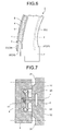
- a pressing member (pressing plate) 8 that presses the intermediary member 4 against the upper protruding element 22 and the lower protruding element 32 (see Fig. 7 ).
- This pressing member 8 is made from a plate-like member having a U-shaped cross section, for example. The inner circumferential surface thereof is brought in contact with the intermediary member 4, and fixed against the upper casing 2 and the lower casing 3 with a bolt (not shown).
- the intermediary member 4 has a projecting element 41, and the pressing member 8 is brought in contact with this projecting element 41. In this manner, the intermediary member 4 is pressed reliably.
- the intermediary member 4 is pressed against and brought in contact with the upper protruding element 22 and the lower protruding element 32 by way of the pressing member 8, the joint area P can be better sealed by the intermediary member 4. In this manner, the outward leakage of the gas can be advantageously suppressed effectively. Furthermore, the pressure capacity of the intermediary member 4 is enforced by the pressing member 8 that presses the intermediary member 4; thus, excessive deformation of the intermediary member 4 can be suppressed. In this manner, the joint area P becomes better sealed.
- the casing 1 it is also preferable to be formed with the groove (relief groove) 5 at the joint area P between the upper casing 2 and the lower casing 3, and collecting channels 51 to 53 that are to be connected to the groove 5 (see Fig. 8 ).
- the gas leaked from the casing 1 through the joint area P travels into the groove 5 at the joint area P, and is collected through the collecting channels 51 to 53.
- an expensive working gas such as helium gas, can be effectively collected advantageously.
- the long thin groove 5 is formed on the joint area P between the upper casing 2 and the lower casing 3 along the circumferential direction of the flange surfaces (see Fig. 3 ).
- the groove 5 is formed with a drilled hole 51 from the bottom thereof, and the drilled hole 51 is connected to a drilled hole 52 formed from the outer circumferential surface of the lower casing 3.
- the drilled hole 52 is installed with a collecting pipe 53 engaged therewith.
- the collecting pipe 53 is, in turn, connected to an external collection line (not shown). In this arrangement, the gas that enters the groove 5 from the joint area P, travels through the drilled hole 51 and the drilled hole 52, is collected via the collecting pipe 53, and is sent to the collection line.
- the pressure in the collecting channels 51 to 53 (the collection line) to be negative with respect to an inside pressure of the casing 1 (groove 5).
- the gas in the groove 5 is actively led into the collecting channels 51 to 53. Therefore, the gas can be effectively collected advantageously.
- the structure of the intermediary member 4 may be less strong, advantageously.
- the surface roughness of an attachment surface of the intermediary member 4 (the contact surface of the intermediary member 4 against the upper protruding element 22 and the lower protruding element 32) can be advantageously reduced.
- the intermediary member 4 can be directly attached onto the upper casing 2 and the lower casing 3 (see Fig. 9 ).
- the intermediary member 4 is arranged so as to cover the outer circumference of the joint area P and to be brought in contact with the outer circumferential surface of the flange element 21 included in the upper casing 2 and the outer circumferential surface of the flange element 31 included in the lower casing 3, and fixed by a joint with a bolt.
- the attaching surface of the intermediary member 4 includes the gasket 9 made of a metal or a resin (e.g., polymer). This arrangement can also suppress outward leakage of the gas.
- the casing (and the fluid machine with the casing) is useful because the casing has the dividable structure, as well as it can suppress outward leakage of the gas from the joint area of the flange surfaces.
Landscapes
- Engineering & Computer Science (AREA)
- Mechanical Engineering (AREA)
- General Engineering & Computer Science (AREA)
- Chemical & Material Sciences (AREA)
- Combustion & Propulsion (AREA)
- Structures Of Non-Positive Displacement Pumps (AREA)
- Turbine Rotor Nozzle Sealing (AREA)
- Gasket Seals (AREA)
Abstract
An object of the present invention is to provide a casing that has a dividable structure and is able to suppress outward leakage of gas from a joint area between flange surfaces, and a fluid machine with such a casing. A casing 1 includes an upper casing 2 and a lower casing 3 jointed in a dividable manner, and a sealing structure that suppresses outward leakage of gas from a joint area P between the upper casing 2 and the lower casing 3. The casing 1 also includes: an upper protruding element 22 that protrudes from an outer circumference of the upper casing 2; a lower protruding element 32 that protrudes from an outer circumference of the lower casing 3; and an intermediary member 4 that is arranged on outer circumferences of the upper protruding element 22 and the lower protruding element 32. The joint area P between the upper casing 2 and the lower casing 3 is extended by the upper protruding element 22 and the lower protruding element 32, and the intermediary member 4 is welded to the upper protruding element 22 and the lower protruding element 32, at a position offset from the joint area P.
Description
- The present invention relates to a casing and a fluid machine, and more particularly, to a casing that has a dividable structure and can suppress outward gas leakage from a joint area of flange surfaces, and to a fluid machine provided with the casing.
- In a casing used for a cylinder of a turbine or a compressor, a dividable structure is generally adopted. Such a casing is presented with a challenge that the outward gas leakage must be suppressed at the flange surface. Particularly, if helium gas is used as working gas, not only the leakage tends to occur much easier than other gas, such as steam, but also it is more expensive. Therefore, in a fluid machine (turbine or compressor) using high-pressure helium gas as working gas, there has been a demand for suppressing the leakage of the working gas more effectively. Therefore, in a known casing, various types of sealing structures are used for the flange section.
- One of the known casings (a sealing structure for the flange section of a pressure container) is disclosed in
Patent Document 1. In flanges of a pressure container of the known casing for enclosing cover gas, including sodium or sodium mist, a ring element, having an I-shaped cross section, is provided onto the entire circumference of the flange. In this manner, the ring element protrudes inwardly from a bolt attaching portion of one of the flanges, which are joined together by flange bolts, into an inter-space between the flanges. At the same time, the other flange includes a ring element, having a J-shaped cross section, on the entire circumference thereof along the former ring element. The edges of these ring elements are engaged and welded together to form a U-shaped sealing element for sealing the cover gas, including the sodium or the sodium mist, inside the container. - [Patent Document 1] Japanese Patent Application Laid Open No.
S55-17712 - An object of the present invention is to provide a casing that has a dividable structure and can prevent the gas from leaking from the joint area of the flange surfaces, and to provide a fluid machine provided with such a casing.
- To achieve the above objects, according to the present invention, a casing having an upper casing and a lower casing that are joined together in a dividable manner, and a sealing structure that prevents outward leakage of gas from a joint area P between the upper casing and the lower casing comprises: an upper protruding element that protrudes from an outer circumference of the upper casing; a lower protruding element that protrudes from an outer circumference of the lower casing; and an intermediary member that is arranged on the outer circumferences of the upper protruding element and the lower protruding element. The joint area P between the upper casing and the lower casing is extended by the upper protruding element and the lower protruding element; and the intermediary member is welded to the upper protruding element and the lower protruding element, at a position offset from the joint area P.
- In this casing, because the upper casing (upper protruding element) and the lower casing (lower protruding element) are welded together by way of the intermediary member, no trace of the weld remains on the joint area P between the flange surfaces when the casing is divided. Therefore, upon assembling the casing again, the remaining welds do not get in the way. In this manner, the upper casing and the lower casing can be held in contact appropriately at the flange surfaces. In this manner, advantageously, the joint area P is better sealed, effectively suppressing the outward leakage of the gas.
- In the casing according to the present invention, the intermediary member seals an outer circumference of the joint area P that is extended by the upper protruding element and the lower protruding element.
- In the casing, because the intermediary member seals the outer circumference of the joint area P that is extended by the upper protruding element and the lower protruding element, the joint area P can be advantageously better sealed, enabling to suppress the outward leakage of the gas more effectively.
- In the casing according to the present invention, each of the upper protruding element and the lower protruding element has a flexible structure that is deformable with the intermediary member being welded.
- In this casing, because the upper protruding element and the lower protruding element have flexible structures, when the upper casing and the lower casing deform, these elements follow the deformation. Therefore, the joined flange surfaces are maintained. In this manner, the joint area P can be sealed reliably, advantageously suppressing the outward leakage of the gas more effectively.
- In the casing according to the present invention, the flexible structure includes a concaving portion formed along extending directions of the upper protruding element and the lower protruding element.
- In this arrangement, when the upper casing and the lower casing deform, the upper protruding element and the lower protruding element make flexible deformation originating from the concaving portions. In this manner, the joint between the flange surfaces is advantageously maintained, ensuring the sealing of the joint area P, thus suppressing outwardly gas leakage effectively.
- In the casing according to the present invention, the intermediary member is provided in a divided manner along the extending directions of the upper protruding element and the lower protruding element.
- In this casing, because the intermediary member is arranged in a divided manner, the intermediary members can be attached more easily, compared with a long intermediary member provided in a singularity.
- In the casing according to the present invention, a groove is formed on the joint area P of the upper casing and the lower casing along an extending direction of the upper casing and the lower casing.
- In this arrangement, the deformation of the flange elements, caused by thermal stress generated upon welding the intermediary members, is absorbed by the grooves. In this manner, the distortion of the joint area P between the upper casing and the lower casing is reduced, ensuring the joint area P to be better sealed. Therefore, advantageously, the outward gas leakage can be suppressed effectively.
- The casing according to the present invention further comprises a pressing member that presses the intermediary member against the upper protruding element and the lower protruding element.
- Because, in this arrangement, the intermediary member is pressed against and brought in contact with the upper protruding element and the lower protruding element by way of the pressing member, the joint area P can be better sealed by the intermediary member.
- The casing according to the present invention further comprises: a groove that is formed on the joint area P between the upper casing and the lower casing; and a gas collection channel that is connected to the groove.
- In this casing, because the gas leaked to the joint area P from the casing travels through the groove provided on the joint area P, and is collected through the collecting channels. In this manner, the outward leakage of the gas can be advantageously suppressed.
- In the casing according to the present invention, the pressure in the collection channel is negative with respect to that in the casing.
- In this casing, because the pressure in the collecting channels is negative with respect to that in the casing, the gas in the groove is actively led into the collecting channels. In this manner, advantageously, the gas can be collected effectively.
- Also, according to the present invention, a casing having an upper casing and a lower casing that are joined together in a dividable manner, and a sealing structure that prevents outward leakage of gas from a joint area P between the upper casing and the lower casing comprises: a groove that is formed on the joint area P between the upper casing and the lower casing; and a gas collection channel that is connected to the groove.
- In this casing, because the gas leaked to the joint area P from the casing travels through the groove provided on the joint area P, and is collected through the collecting channels. In this manner, the outward leakage of the gas can be advantageously suppressed.
- Further, according to the present invention, a fluid machine has a cylinder comprising the above described casing.
- In the casing according to the present invention, because the upper casing and the lower casing are welded together by way of the intermediary member, no trace of the weld remains on the joint area P between the flange surfaces when the casing is divided. Therefore, upon assembling the casing again, the remaining welds do not get in the way. In this manner, the upper casing and the lower casing can be held in contact appropriately at the flange surfaces. In this manner, advantageously, the joint area P is better sealed, effectively suppressing the outward leakage of the gas.
-
- [
Fig. 1] Fig. 1 is a structural diagram of an exemplary application of a casing according to an embodiment of the present invention. - [
Fig. 2] Fig. 2 is a cross-sectional view of the casing shown inFig. 1 across a line A-A. - [
Fig. 3] Fig. 3 is a cross-sectional view of the casing shown inFig. 2 across a line B. - [
Fig. 4] Fig. 4 is a cross-sectional view of a protruding element and an intermediary member of the casing shown inFig. 2 . - [
Fig. 5] Fig. 5 is an illustrative diagram of a nut in the casing shown inFig. 2 . - [
Fig. 6] Fig. 6 is an illustrative diagram of a modification of the casing shown inFig. 2 . - [
Fig. 7] Fig. 7 is an illustrative diagram of another modification of the casing shown inFig. 2 . - [
Fig. 8] Fig. 8 is an illustrative diagram of still another modification of the casing shown inFig. 2 . - [
Fig. 9] Fig. 9 is an illustrative diagram of still another modification of the casing shown inFig. 2 . -
- 1
- casing
- 2
- upper casing
- 21
- flange element
- 22
- upper protruding element
- 23
- concaving portion
- 3
- lower casing
- 31
- flange element
- 32
- lower protruding element
- 33
- concaving portion
- 4
- intermediary member
- 41
- projecting element
- 42
- gasket
- 5
- groove
- 51
- drilled hole
- 52
- drilled hole
- 53
- collecting pipe
- 61
- bolt
- 62
- nut
- 63
- gasket
- 7
- gasket
- 8
- pressing member
- 9
- gasket
- 10
- turbine
- 11
- inner casing
- 12
- rotor
- 13
- rotor vane
- 14
- stator vane
- 15
- bearings
- 16
- inlet portion
- 17
- outlet portion
- The present invention will be now described in detail below, with reference to the drawings. It should be understood that these embodiments are not intended to limit the present invention in any way. Moreover, elements described in the embodiments shall include those that are easily replaceable by those in the art, or elements that are substantially the same as those described herein. A plurality of modifications of the present invention presented herein can be combined in any way within the scope that is obvious to those in the art.
-
Fig. 1 is a structural diagram of an exemplary application of a casing according to an embodiment of the present invention.Fig. 2 is a cross-sectional view of the casing shown inFig. 1 (Fig. 2 ) across a line A-A, and a cross-sectional view across a line B (Fig. 3 ).Fig. 4 is a cross-sectional view of a protruding element and an intermediary member of the casing shown inFig. 1 .Fig. 5 is an illustrative diagram of a nut in the casing shown inFig. 1 .Figs. 6 to 9 are illustrative diagrams of modifications of the casing shown inFig. 2 . - A
casing 1 is characterized by its dividable structure, and its capability to suppress outward gas leakage from a joint area P of flange surfaces. Thecasing 1 is applied to cylinder flanges, for example, of a turbine or a compressor. In this embodiment, thecasing 1 is described to be applied to cylinder flanges of aturbine 10. - The
turbine 10 includes a casing (outer casing) 1 that makes up the cylinder flanges, aninner casing 11, arotor 12, a plurality ofrotor vanes 13, and a plurality of stator vanes 14 (seeFig. 1 ). Theinner casing 11 is housed inside thecasing 1. A channel R for working gas is provided in theinner casing 11. In thisturbine 10, helium gas is used as the working gas. Therotor 12 is supported bybearings casing 1 and theinner casing 11. The rotor vanes 13 and thestator vanes 14 are arranged in a staggered manner on an outer circumference of therotor 12 in the axial direction to form a part of the channel R for the working gas. When theturbine 10 is operated, the high-temperature and high-pressure working gas is introduced to the channel R in theinner casing 11 from aninlet portion 16, and passes through therotor vanes 13 and thestator vanes 14 while expanding in its volume. In this manner, therotor 12 is rotated with therotor vanes 13 to generate a driving force. The working gas, passing through therotor vanes 13 and thestator vanes 14, will be collected to a collection line (not shown) via anoutlet portion 17. - The
casing 1 includes anupper casing 2 and alower casing 3, and these are jointed together along a horizontal dividing surface (joint area P), in a dividable manner in upward and downward directions, to form the casing 1 (seeFig. 2 ). Specifically, aflange element 21 of theupper casing 2 and aflange element 31 of thelower casing 3 are jointed together, and fastened with abolt 61 and anut 62. On the flange surface of theupper casing 2, ametal gasket 7 is provided along the circumferential direction of thecasing 1. The joint area P between theupper casing 2 and thelower casing 3 is sealed by thisgasket 7 and a surface contact between theflange elements upper casing 2 and thelower casing 3, it is preferable to provide a machine finish of approximately Ra 3.2 to Ra 1.6. In this manner, the surface contact between theflange elements - An upper protruding
element 22 is provided on theflange element 21 of theupper casing 2, and a lower protrudingelement 32 is provided on theflange element 31 of the lower casing 3 (seeFigs. 2 to 4 ). The upper protrudingelement 22 and the lower protrudingelement 32 protrude from outer circumference surfaces of theupper casing 2 and thelower casing 3, respectively, toward the outside of thecasing 1. The joint area P between theupper casing 2 and thelower casing 3 is extended outwardly from thecasing 1 by way of the upper protrudingelement 22 and the lower protrudingelement 32. The upper protrudingelement 22 and the lower protrudingelement 32 are formed along the circumference of the flange surfaces P, approximately over the entire circumference of thecasing 1. - An intermediary member (contact board) 4 is arranged in contact with the outer circumference of the upper protruding
element 22 and the lower protrudingelement 32. Thisintermediary member 4 is a plate-shaped member, and arranged approximately over the entire circumference of the upper protrudingelement 22 and the lower protrudingelement 32. Theintermediary member 4 is welded to the upper protrudingelement 22 and the lower protrudingelement 32, respectively, at a position offset from the joint area P of the flange surfaces. In other words, the upper protrudingelement 22 and the lower protrudingelement 32 are welded together by way of theintermediary member 4, and the contacting surface between the upper protrudingelement 22 and the lower protrudingelement 32 is not welded together. Theintermediary member 4 is arranged on the outer circumference of the joint area P that is extended by the upper protrudingelement 22 and the lower protrudingelement 32, sealing the joint area P from the outer circumferential direction. - Upon maintaining the
turbine 10, thebolt 61 and thenut 62 that fasten theupper casing 2 and thelower casing 3 together, are removed, the weld on theintermediary member 4 is scraped away, and thecasing 1 is divided. Because, in thecasing 1, the upper casing 2 (upper protruding element 22) and the lower casing 3 (lower protruding element 32) are welded together by way of the intermediary member 4 (seeFig. 4 ), no trace of the weld remains on the joint area P of the flange surfaces when thecasing 1 is divided. Therefore, upon assembling thecasing 1 again, the remaining welds do not get in the way. In this manner, theupper casing 2 and thelower casing 3 can be held in contact appropriately at the flange surfaces. In this manner, advantageously, the joint area P is better sealed, effectively suppressing the outward leakage of the gas. - Furthermore, according to this structure, the
intermediary member 4 is welded to the upper protrudingelement 22 and the lower protrudingelement 32. Therefore, in comparison with a structure where theintermediary member 4 is directly welded to the circumferential surfaces of theupper casing 2 and the lower casing 3 (not shown), the welds on theintermediary member 4 can be advantageously removed and welded together again more easily. - Still furthermore, the structure can be achieved by providing small additional protruding elements (the upper protruding
element 22 and the lower protruding element 32) onto a known casing. Still furthermore, the process applied to the flange surface P of theupper casing 2 and the flange surface of thelower casing 3 may be of a surface roughness approximately of the same level as that of the known casing. Still furthermore, welding of theintermediary member 4 is small; therefore, it is possible to reduce a maintenance period (overhauling period) and a labor cost required for the welding. - Still furthermore, in the
casing 1, because theintermediary member 4 seals the outer circumference of the joint area P that is extended by the upper protrudingelement 22 and the lower protruding element 32 (seeFig. 4 ), the joint area P can be advantageously better sealed, enabling to suppress the outward leakage of the gas more effectively. - In the
casing 1, it is also preferable for the upper protrudingelement 22 and the lower protrudingelement 32 that are welded with theintermediary member 4 to have flexible structures, so that they can be deformed (seeFigs. 2 and4 ). For example, if thecasing 1 is used as a cylinder (pressure-resistant container) of theturbine 10, thecasing 1 goes through a great change in internal pressure and temperature during the turbine operation.
Then, theflange element 21 of theupper casing 2 and theflange element 31 of thelower casing 3, facing each other, are moved in relation to each other, thus deforming the joint area P between the flange surfaces. If the upper protrudingelement 22 and the lower protrudingelement 32 are flexible in structure, these elements follow the deformation, maintaining the joint between the flange surfaces. In this manner, the sealing at the joint area P is advantageously ensured, as well as the outward leakage of the gas is suppressed more effectively. - Still furthermore, in this arrangement, when the
intermediary member 4 is welded together again, the upper protrudingelement 22 and the lower protrudingelement 32 deform flexibly, and release the deformation caused by thermal stress. Excessive residual stress due to welding decreases in turn, further reducing the deformation (hazardous deformation) at the joint area P between theupper casing 2 and thelower casing 3. In this manner, the sealing at the joint area P is advantageously ensured, as well as the outward leakage of the gas is suppressed more effectively. - For example, the flexible structures are provided as
concaving portions element 22 and the lower protruding element 32 (seeFig. 4 ). Specifically, the upper protrudingelement 22 and lower protrudingelement 32 have L-shaped cross sections in the radial direction of thecasing 1, and are curved (bent) approximately perpendicularly to the flange surfaces. The upper protrudingelement 22 and the lower protrudingelement 32 protrude from the outer circumference of thecasing 1 in an approximate T shape along the flange surfaces P as a symmetric axis. Theintermediary member 4 is brought in contact with the top portion of the T-shaped element. Both ends of theintermediary member 4 are welded to the upper protrudingelement 22 and the lower protrudingelement 32, respectively. - In this arrangement, when the
upper casing 2 and thelower casing 3 deform, the upper protrudingelement 22 and the lower protrudingelement 32 make flexible deformation originating from theconcaving portions - In this
casing 1, theupper casing 2 and thelower casing 3 are jointed together by thebolt 61 and thenut 62 at theflange elements bolt 61 penetrates through both of theflange elements bolt 61. At this time, the nuts 62, 62 are brought in contact with the outer circumference surface of theflange elements flange element casing 1 at the joint area P. - Therefore, in this
casing 1, it is preferable to provide a sealing structure to thebolt 61 and the nuts 62 (seeFig. 5 ). For example, ametal gasket 63 is provided on a contact area between thenut 62 and the outer circumferential surface of each of theflange elements 21, 31 (contact surfaces of the nuts 62). Thisgasket 63 seals the gap between thenut 62 and each of theflange elements - In this arrangement, it is also preferable to improve the surface contact (surface pressing pressure) between the
nut 62 and each of theflange element nut 62 and each of theflange elements nut 62 and each of theflange elements - Still furthermore, because, in the arrangement, the contact surface of the
nut 62 is relatively small in radius and is circular in shape, aninexpensive gasket 9 can be used. Still furthermore, the contact surface of thenut 62 and each of theelements - In the
casing 1, it is also preferable for theintermediary member 4 to be arranged in a dividable manner, in the extending direction of the upper protrudingelement 22 and the lower protruding element 32 (seeFig. 6 ). In other words, a plurality ofintermediary members 4 are arranged along the upper protrudingelement 22 and the lower protrudingelement 32, and theseintermediary members 4 seal the joint area P between theupper casing 2 and thelower casing 3. - In this arrangement, because the
intermediary members 4 are arranged in a dividable manner, theintermediary members 4 can be advantageously mounted more easily, compared with the longintermediary member 4 arranged in singularity (seeFig. 2 ). In this arrangement, it is preferable to arrange theintermediary members 4 with a small inter-space (the inter-space between the adjacentintermediary members 4, 4) so that the joint area P is better sealed. - In the
casing 1, it is also preferable for theupper casing 2 and thelower casing 3 to include agroove 5, respectively, on the joint area P (seeFigs. 2 to 4 ). Thesegrooves 5 extend along the upper protrudingelement 22 and the lower protrudingelement 32 in the circumferential direction of theflange elements groove 5 is provided correspondingly to the welded area of theintermediary members 4. Thegroove 5 may be formed in plurality in a divided manner (seeFig. 6 ). - In this arrangement, the deformation of the
flange elements intermediary members 4, is absorbed by thegrooves 5. In this manner, the distortion of the joint area P between theupper casing 2 and thelower casing 3 is reduced, ensuring the joint area P to be better sealed. Therefore, advantageously, the outward gas leakage can be suppressed effectively. - In the
casing 1, it is also preferable to include a pressing member (pressing plate) 8 that presses theintermediary member 4 against the upper protrudingelement 22 and the lower protruding element 32 (seeFig. 7 ). Thispressing member 8 is made from a plate-like member having a U-shaped cross section, for example. The inner circumferential surface thereof is brought in contact with theintermediary member 4, and fixed against theupper casing 2 and thelower casing 3 with a bolt (not shown). Theintermediary member 4 has a projectingelement 41, and thepressing member 8 is brought in contact with this projectingelement 41. In this manner, theintermediary member 4 is pressed reliably. - Because, in this arrangement, the
intermediary member 4 is pressed against and brought in contact with the upper protrudingelement 22 and the lower protrudingelement 32 by way of thepressing member 8, the joint area P can be better sealed by theintermediary member 4. In this manner, the outward leakage of the gas can be advantageously suppressed effectively. Furthermore, the pressure capacity of theintermediary member 4 is enforced by the pressingmember 8 that presses theintermediary member 4; thus, excessive deformation of theintermediary member 4 can be suppressed. In this manner, the joint area P becomes better sealed. - In the
casing 1, it is also preferable to be formed with the groove (relief groove) 5 at the joint area P between theupper casing 2 and thelower casing 3, and collectingchannels 51 to 53 that are to be connected to the groove 5 (seeFig. 8 ). In this arrangement, the gas leaked from thecasing 1 through the joint area P travels into thegroove 5 at the joint area P, and is collected through the collectingchannels 51 to 53. In this manner, the outward gas leakage from thecasing 1 can be advantageously suppressed. For example, an expensive working gas, such as helium gas, can be effectively collected advantageously. - For example, the long
thin groove 5 is formed on the joint area P between theupper casing 2 and thelower casing 3 along the circumferential direction of the flange surfaces (seeFig. 3 ). Thegroove 5 is formed with a drilledhole 51 from the bottom thereof, and the drilledhole 51 is connected to a drilledhole 52 formed from the outer circumferential surface of thelower casing 3. The drilledhole 52 is installed with a collectingpipe 53 engaged therewith. The collectingpipe 53 is, in turn, connected to an external collection line (not shown). In this arrangement, the gas that enters thegroove 5 from the joint area P, travels through the drilledhole 51 and the drilledhole 52, is collected via the collectingpipe 53, and is sent to the collection line. - In the arrangement, it is also preferable that the pressure in the collecting
channels 51 to 53 (the collection line) to be negative with respect to an inside pressure of the casing 1 (groove 5). In this arrangement, the gas in thegroove 5 is actively led into the collectingchannels 51 to 53. Therefore, the gas can be effectively collected advantageously. Still furthermore, in this arrangement, because the pressure at the joint area P can be reduced at the same time, the structure of theintermediary member 4 may be less strong, advantageously. Still furthermore, because a reduced amount of the gas leaks out between the upper protrudingelement 22 and the lower protrudingelement 32, the surface roughness of an attachment surface of the intermediary member 4 (the contact surface of theintermediary member 4 against the upper protrudingelement 22 and the lower protruding element 32) can be advantageously reduced. - Still furthermore, in the arrangement, the upper protruding
element 22 and the lower protrudingelement 32 can be omitted, and theintermediary member 4 can be directly attached onto theupper casing 2 and the lower casing 3 (seeFig. 9 ). For example, theintermediary member 4 is arranged so as to cover the outer circumference of the joint area P and to be brought in contact with the outer circumferential surface of theflange element 21 included in theupper casing 2 and the outer circumferential surface of theflange element 31 included in thelower casing 3, and fixed by a joint with a bolt. The attaching surface of theintermediary member 4 includes thegasket 9 made of a metal or a resin (e.g., polymer). This arrangement can also suppress outward leakage of the gas. - As described above, the casing (and the fluid machine with the casing) is useful because the casing has the dividable structure, as well as it can suppress outward leakage of the gas from the joint area of the flange surfaces.
Claims (11)
- A casing having an upper casing and a lower casing that are joined together in a dividable manner, and a sealing structure that prevents outward leakage of gas from a joint area P between the upper casing and the lower casing, the casing comprising:an upper protruding element that protrudes from an outer circumference of the upper casing;a lower protruding element that protrudes from an outer circumference of the lower casing; andan intermediary member that is arranged on the outer circumferences of the upper protruding element and the lower protruding element, whereinthe joint area P between the upper casing and the lower casing is extended by the upper protruding element and the lower protruding element; andthe intermediary member is welded to the upper protruding element and the lower protruding element, at a position offset from the joint area P.
- The casing according to claim 1, wherein the intermediary member seals an outer circumference of the joint area P that is extended by the upper protruding element and the lower protruding element.
- The casing according to claim 1 or 2, wherein each of the upper protruding element and the lower protruding element has a flexible structure that is deformable with the intermediary member being welded.
- The casing according to claim 3, wherein the flexible structure includes a concaving portion formed along extending directions of the upper protruding element and the lower protruding element.
- The casing according to any one of claims 1 to 4, wherein the intermediary member is provided in a divided manner along the extending directions of the upper protruding element and the lower protruding element.
- The casing according to any one of claims 1 to 5, wherein a groove is formed on the joint area P of the upper casing and the lower casing along an extending direction of the upper casing and the lower casing.
- The casing according to any one of claims 1 to 6, further comprising a pressing member that presses the intermediary member against the upper protruding element and the lower protruding element.
- The casing according to any one of claims 1 to 7, further comprising:a groove that is formed on the joint area P between the upper casing and the lower casing; anda gas collection channel that is connected to the groove.
- The casing according to claim 8, wherein the pressure in the collection channel is negative with respect to that in the casing.
- A casing having an upper casing and a lower casing that are joined together in a dividable manner, and a sealing structure that prevents outward leakage of gas from a joint area P between the upper casing and the lower casing, the casing comprising:a groove that is formed on the joint area P between the upper casing and the lower casing; anda gas collection channel that is connected to the groove.
- A fluid machine having a cylinder comprising the casing according to any one of claims 1 to 10.
Applications Claiming Priority (2)
| Application Number | Priority Date | Filing Date | Title |
|---|---|---|---|
| JP2006037084A JP4786362B2 (en) | 2006-02-14 | 2006-02-14 | Casing and fluid machinery |
| PCT/JP2007/052496 WO2007094306A1 (en) | 2006-02-14 | 2007-02-13 | Casing and fluid machine |
Publications (1)
| Publication Number | Publication Date |
|---|---|
| EP1992790A1 true EP1992790A1 (en) | 2008-11-19 |
Family
ID=38371486
Family Applications (1)
| Application Number | Title | Priority Date | Filing Date |
|---|---|---|---|
| EP07714078A Withdrawn EP1992790A1 (en) | 2006-02-14 | 2007-02-13 | Casing and fluid machine |
Country Status (5)
| Country | Link |
|---|---|
| US (1) | US8118551B2 (en) |
| EP (1) | EP1992790A1 (en) |
| JP (1) | JP4786362B2 (en) |
| WO (1) | WO2007094306A1 (en) |
| ZA (1) | ZA200806870B (en) |
Families Citing this family (13)
| Publication number | Priority date | Publication date | Assignee | Title |
|---|---|---|---|---|
| EP2304192B1 (en) * | 2008-03-31 | 2014-12-10 | Mitsubishi Heavy Industries, Ltd. | Rotary machine scroll structure and rotary machine |
| EP2276912B1 (en) * | 2008-03-31 | 2017-10-25 | Mitsubishi Heavy Industries, Ltd. | Rotary machine |
| JP5433183B2 (en) | 2008-08-07 | 2014-03-05 | 株式会社東芝 | Steam turbine and steam turbine plant system |
| US8128353B2 (en) * | 2008-09-30 | 2012-03-06 | General Electric Company | Method and apparatus for matching the thermal mass and stiffness of bolted split rings |
| JP5398311B2 (en) * | 2009-03-09 | 2014-01-29 | 三菱重工業株式会社 | Enclosure sealing structure and fluid machinery |
| US20130309085A1 (en) * | 2012-05-15 | 2013-11-21 | Solar Turbines Incorporated | Compressor case overhaul |
| JP6099474B2 (en) * | 2013-01-23 | 2017-03-22 | 三菱重工業株式会社 | Cabin, rotating machine, car assembly method |
| ITCO20130044A1 (en) | 2013-10-08 | 2015-04-09 | Nuovo Pignone Srl | CASE FOR ROTARY MACHINE AND ROTARY MACHINE INCLUDING SUCH CASH |
| US10337353B2 (en) | 2014-12-31 | 2019-07-02 | General Electric Company | Casing ring assembly with flowpath conduction cut |
| JP2017040186A (en) * | 2015-08-19 | 2017-02-23 | 株式会社荏原製作所 | Fluid machine |
| DE102016211231A1 (en) * | 2016-06-23 | 2017-12-28 | Rolls-Royce Deutschland Ltd & Co Kg | Housing for a rotor of an engine |
| KR101901772B1 (en) * | 2016-11-17 | 2018-09-28 | 두산중공업 주식회사 | Bearing housing structure for easy maintenance without disassembling struts |
| JP2026008809A (en) * | 2024-06-28 | 2026-01-19 | ジーイー・ベルノバ・テクノロジー・ゲーエムベーハー | Coupling flange with shim in industrial machinery and related method |
Family Cites Families (12)
| Publication number | Priority date | Publication date | Assignee | Title |
|---|---|---|---|---|
| US1246091A (en) * | 1917-01-16 | 1917-11-13 | Henry E Haller | Pipe-joint. |
| US3359626A (en) * | 1965-04-21 | 1967-12-26 | Du Pont | Process for joining glass-lined metal conduits |
| JPS5653676B2 (en) * | 1974-06-03 | 1981-12-21 | ||
| JPS5943674B2 (en) | 1978-07-21 | 1984-10-23 | 株式会社日立製作所 | Seal structure of pressure vessel flange |
| JPS5560406U (en) | 1978-10-20 | 1980-04-24 | ||
| JPS5758165U (en) | 1980-09-24 | 1982-04-06 | ||
| JPS57120724U (en) * | 1981-01-19 | 1982-07-27 | ||
| JPS57212305A (en) * | 1981-06-24 | 1982-12-27 | Hitachi Ltd | Turbine casing |
| JPS61192503U (en) | 1985-05-24 | 1986-11-29 | ||
| US4815650A (en) * | 1987-12-04 | 1989-03-28 | James Reaux | Hydraulically activated welding flange |
| FR2800797B1 (en) | 1999-11-10 | 2001-12-07 | Snecma | ASSEMBLY OF A RING BORDING A TURBINE TO THE TURBINE STRUCTURE |
| JP5943674B2 (en) | 2012-03-28 | 2016-07-05 | 三菱重工業株式会社 | Spacecraft |
-
2006
- 2006-02-14 JP JP2006037084A patent/JP4786362B2/en not_active Expired - Lifetime
-
2007
- 2007-02-13 EP EP07714078A patent/EP1992790A1/en not_active Withdrawn
- 2007-02-13 WO PCT/JP2007/052496 patent/WO2007094306A1/en not_active Ceased
- 2007-02-13 US US12/279,222 patent/US8118551B2/en active Active
- 2007-02-13 ZA ZA200806870A patent/ZA200806870B/en unknown
Non-Patent Citations (1)
| Title |
|---|
| See references of WO2007094306A1 * |
Also Published As
| Publication number | Publication date |
|---|---|
| JP4786362B2 (en) | 2011-10-05 |
| US20090202345A1 (en) | 2009-08-13 |
| JP2007218119A (en) | 2007-08-30 |
| US8118551B2 (en) | 2012-02-21 |
| ZA200806870B (en) | 2009-12-30 |
| WO2007094306A1 (en) | 2007-08-23 |
Similar Documents
| Publication | Publication Date | Title |
|---|---|---|
| US8118551B2 (en) | Casing and fluid machine | |
| EP3246542B1 (en) | Sealing structure for turbocharger housing | |
| US9234440B2 (en) | Structure for gas turbine casing | |
| JP6858856B2 (en) | Turbocharger | |
| JP6240307B2 (en) | Sheet metal turbine housing | |
| US8684670B2 (en) | Sealing mechanism with bellows and steam turbine provided with the sealing mechanism | |
| EP2957796A1 (en) | Brush seal assembly | |
| US9091348B2 (en) | Shaft sealing apparatus and rotating machine equipped therewith | |
| US10731492B2 (en) | Component joint | |
| KR20190086566A (en) | A turbocharger having a sealing surface between the nozzle ring and the turbine housing | |
| EP3008294A1 (en) | Sealing arrangement for a turbomachine | |
| CA2618119C (en) | Hold-down plate for securing a component | |
| CN215258524U (en) | Leakage blocking device for leakage of low-pressure flange joint surface | |
| JP4436273B2 (en) | Turbine partition plate and turbine provided with the same | |
| CN109441568B (en) | High-efficiency low-pressure baffle plate sleeve device and assembly method thereof | |
| JP7416486B2 (en) | Repair joint device and its assembly method | |
| JP2014159883A (en) | Steam condenser | |
| CN204477304U (en) | The mechanical seal of a kind of unit loading type reactor | |
| CN111678646A (en) | Engine transition bearing cavity tightness inspection device | |
| JP2006017074A (en) | Seal device | |
| KR102918614B1 (en) | A rotor assembly of a gas turbine engine | |
| CN211449623U (en) | Combined metal sealing structure | |
| CN104696525A (en) | Cartridge mechanical seal for reactor | |
| CN103306986A (en) | Multi-stage pump | |
| JP5610692B2 (en) | Fluid leakage prevention device |
Legal Events
| Date | Code | Title | Description |
|---|---|---|---|
| PUAI | Public reference made under article 153(3) epc to a published international application that has entered the european phase |
Free format text: ORIGINAL CODE: 0009012 |
|
| 17P | Request for examination filed |
Effective date: 20080811 |
|
| AK | Designated contracting states |
Kind code of ref document: A1 Designated state(s): DE FR GB |
|
| DAX | Request for extension of the european patent (deleted) | ||
| RBV | Designated contracting states (corrected) |
Designated state(s): DE FR GB |
|
| STAA | Information on the status of an ep patent application or granted ep patent |
Free format text: STATUS: THE APPLICATION HAS BEEN WITHDRAWN |
|
| 18W | Application withdrawn |
Effective date: 20111220 |