EP1992682A1 - Apparatus for real-time detection of nucleic acid amplification product - Google Patents
Apparatus for real-time detection of nucleic acid amplification product Download PDFInfo
- Publication number
- EP1992682A1 EP1992682A1 EP07737629A EP07737629A EP1992682A1 EP 1992682 A1 EP1992682 A1 EP 1992682A1 EP 07737629 A EP07737629 A EP 07737629A EP 07737629 A EP07737629 A EP 07737629A EP 1992682 A1 EP1992682 A1 EP 1992682A1
- Authority
- EP
- European Patent Office
- Prior art keywords
- dna
- fluorescence
- reaction
- value
- strength
- Prior art date
- Legal status (The legal status is an assumption and is not a legal conclusion. Google has not performed a legal analysis and makes no representation as to the accuracy of the status listed.)
- Granted
Links
Images


Classifications
-
- C—CHEMISTRY; METALLURGY
- C12—BIOCHEMISTRY; BEER; SPIRITS; WINE; VINEGAR; MICROBIOLOGY; ENZYMOLOGY; MUTATION OR GENETIC ENGINEERING
- C12Q—MEASURING OR TESTING PROCESSES INVOLVING ENZYMES, NUCLEIC ACIDS OR MICROORGANISMS; COMPOSITIONS OR TEST PAPERS THEREFOR; PROCESSES OF PREPARING SUCH COMPOSITIONS; CONDITION-RESPONSIVE CONTROL IN MICROBIOLOGICAL OR ENZYMOLOGICAL PROCESSES
- C12Q1/00—Measuring or testing processes involving enzymes, nucleic acids or microorganisms; Compositions therefor; Processes of preparing such compositions
- C12Q1/68—Measuring or testing processes involving enzymes, nucleic acids or microorganisms; Compositions therefor; Processes of preparing such compositions involving nucleic acids
- C12Q1/6844—Nucleic acid amplification reactions
- C12Q1/6851—Quantitative amplification
-
- C—CHEMISTRY; METALLURGY
- C12—BIOCHEMISTRY; BEER; SPIRITS; WINE; VINEGAR; MICROBIOLOGY; ENZYMOLOGY; MUTATION OR GENETIC ENGINEERING
- C12M—APPARATUS FOR ENZYMOLOGY OR MICROBIOLOGY; APPARATUS FOR CULTURING MICROORGANISMS FOR PRODUCING BIOMASS, FOR GROWING CELLS OR FOR OBTAINING FERMENTATION OR METABOLIC PRODUCTS, i.e. BIOREACTORS OR FERMENTERS
- C12M1/00—Apparatus for enzymology or microbiology
- C12M1/34—Measuring or testing with condition measuring or sensing means, e.g. colony counters
-
- C—CHEMISTRY; METALLURGY
- C12—BIOCHEMISTRY; BEER; SPIRITS; WINE; VINEGAR; MICROBIOLOGY; ENZYMOLOGY; MUTATION OR GENETIC ENGINEERING
- C12Q—MEASURING OR TESTING PROCESSES INVOLVING ENZYMES, NUCLEIC ACIDS OR MICROORGANISMS; COMPOSITIONS OR TEST PAPERS THEREFOR; PROCESSES OF PREPARING SUCH COMPOSITIONS; CONDITION-RESPONSIVE CONTROL IN MICROBIOLOGICAL OR ENZYMOLOGICAL PROCESSES
- C12Q1/00—Measuring or testing processes involving enzymes, nucleic acids or microorganisms; Compositions therefor; Processes of preparing such compositions
- C12Q1/68—Measuring or testing processes involving enzymes, nucleic acids or microorganisms; Compositions therefor; Processes of preparing such compositions involving nucleic acids
- C12Q1/6844—Nucleic acid amplification reactions
- C12Q1/686—Polymerase chain reaction [PCR]
-
- C—CHEMISTRY; METALLURGY
- C12—BIOCHEMISTRY; BEER; SPIRITS; WINE; VINEGAR; MICROBIOLOGY; ENZYMOLOGY; MUTATION OR GENETIC ENGINEERING
- C12M—APPARATUS FOR ENZYMOLOGY OR MICROBIOLOGY; APPARATUS FOR CULTURING MICROORGANISMS FOR PRODUCING BIOMASS, FOR GROWING CELLS OR FOR OBTAINING FERMENTATION OR METABOLIC PRODUCTS, i.e. BIOREACTORS OR FERMENTERS
- C12M1/00—Apparatus for enzymology or microbiology
-
- C—CHEMISTRY; METALLURGY
- C12—BIOCHEMISTRY; BEER; SPIRITS; WINE; VINEGAR; MICROBIOLOGY; ENZYMOLOGY; MUTATION OR GENETIC ENGINEERING
- C12N—MICROORGANISMS OR ENZYMES; COMPOSITIONS THEREOF; PROPAGATING, PRESERVING, OR MAINTAINING MICROORGANISMS; MUTATION OR GENETIC ENGINEERING; CULTURE MEDIA
- C12N15/00—Mutation or genetic engineering; DNA or RNA concerning genetic engineering, vectors, e.g. plasmids, or their isolation, preparation or purification; Use of hosts therefor
-
- G—PHYSICS
- G01—MEASURING; TESTING
- G01N—INVESTIGATING OR ANALYSING MATERIALS BY DETERMINING THEIR CHEMICAL OR PHYSICAL PROPERTIES
- G01N21/00—Investigating or analysing materials by the use of optical means, i.e. using sub-millimetre waves, infrared, visible or ultraviolet light
- G01N21/62—Systems in which the material investigated is excited whereby it emits light or causes a change in wavelength of the incident light
- G01N21/63—Systems in which the material investigated is excited whereby it emits light or causes a change in wavelength of the incident light optically excited
- G01N21/64—Fluorescence; Phosphorescence
-
- G—PHYSICS
- G01—MEASURING; TESTING
- G01N—INVESTIGATING OR ANALYSING MATERIALS BY DETERMINING THEIR CHEMICAL OR PHYSICAL PROPERTIES
- G01N21/00—Investigating or analysing materials by the use of optical means, i.e. using sub-millimetre waves, infrared, visible or ultraviolet light
- G01N21/62—Systems in which the material investigated is excited whereby it emits light or causes a change in wavelength of the incident light
- G01N21/63—Systems in which the material investigated is excited whereby it emits light or causes a change in wavelength of the incident light optically excited
- G01N21/64—Fluorescence; Phosphorescence
- G01N21/645—Specially adapted constructive features of fluorimeters
- G01N21/6452—Individual samples arranged in a regular 2D-array, e.g. multiwell plates
Definitions
- This invention relates to an apparatus for real-time detecting a polynucleotide product obtained from a polymerase chain reaction (PCR).
- PCR polymerase chain reaction
- a PCR is a cyclic enzyme reaction to replicate a DNA chain.
- As the PCR is used as a template of a cycle in which PCR products (nucleic acid amplification products) replicated in previous cycles are consecutive, arrayed target molecules can be exponentially amplified.
- a real time PCR is to excite fluorescent material by irradiating a PCR product with excitation light using, for example, array-specific probes (TaqMan probes) marked with two different kinds of fluorescent pigments interfering with each other, measure the strength of the fluorescence and monitor amplification of the PCR products in real time.
- a threshold ((6) in Fig. 7 ) is set in an exponential amplification region of an amplification curve for existing samples, and a point (threshold cycle number (Ct). (8) in Fig. 8 ) at which the threshold intersects the amplification curve is calculated.
- Ct threshold cycle number
- the initial amount of DNA of the test sample is estimated based on the calibration curve. This enables correct quantitativeness based on a PCR amplification speed theory.
- a horizontal axis represents the cycle number and a vertical axis represents the fluorescence strength.
- the fluorescence strength is exponentially amplified ((5) in Fig. 7 ) at the cycle initial stage, linearly amplified ((6) in Fig. 7 ) at the cycle middle stage, and not amplified ((7) in Fig. 7 ) by a plateau effect at the cycle late stage.
- a vessel called a micro plate having a plurality (for example, 96) of wells (reactive regions constituted by concave portions) is being used in common and reactive solution having a predetermined initial DNA concentration is divisionally poured in the wells.
- reactive solution having a predetermined initial DNA concentration is divisionally poured in the wells.
- an amplification curve for each of the wells of the reactive vessel becomes unbalanced due to the following apparatus error factors
- the reactive vessel mainly uses a cheap method in which the above-mentioned seal film with an adhesive is attached to the entire region of a single side and the wells are cover by a cap.
- the wells are irradiated with excitation light through the seal film and fluorescence generated from the PCR product (reaction product) is detected by a light detecting part such as a CCD camera through the seal film (these components constitute an optical system).
- a light detecting part such as a CCD camera
- these components constitute an optical system.
- Fig. 4 shows an actual image of a reactive vessel before PCR, which is detected by an optical detecting part. While the circumference of wells of the reactive vessel appears to be black as a whole, the brightness of pixels of the image as a background is not necessarily constant and there occurs a spot due to contamination of the optical system or way-out light as indicated by (1) in the figure. When a PCR reaction is initiated, this spot overlaps with images (96 images appearing to be round in Fig. 5 ) of the wells as indicated by (2) in Fig. 5 , wastefully adding to the fluorescence strength of the wells.
- empty reactive vessels containing no DNA are initially prepared, and fluorescence strengths for wells are measured in such an empty state and are stored as standard correction values. Then, by performing a correcting process in which the stored correction values are subtracted from measurement values of actual fluorescence strengths, such correction of the optical system is performed.
- the stored correction values are subtracted from measurement values of actual fluorescence strengths, such correction of the optical system is performed.
- correction values by other standard empty reactive vessels are used, there occurs a problem of errors in measurement values.
- Patent Document 2 although a first fluorescence signal is corrected with a second fluorescence signal, since a solution that generates second fluorescence for reference must be added to a solution that generates first fluorescence to be originally measured, work becomes complicated and costs are raised. In addition, the solution that generates the second fluorescence can not give any effect if it can not be divisionally poured and measured with very high precision. In addition, since an especial optical filter has to be used to measure the second fluorescence and has to be exchanged for the solution that generates the first fluorescence and the solution that generates the second fluorescence every measurement, there is a problem that it takes extra time to acquire and process data.
- the present invention has made to overcome the above technical problems and it is an object of the invention to provide an apparatus for detecting a nucleic acid amplification product in real time, which is capable of effectively excluding or reducing apparatus error factors without using a second fluorescence signal used for correction.
- an apparatus for detecting fluorescence strength from a nucleic acid amplification product in each of a plurality of reaction regions given with temperature cycles in real time wherein a fluorescence measurement value [DNA]raw obtained from the reaction region and a fluorescence measurement value [DNA]bg obtained from regions other than the reaction region adjacent to the reaction region are detected, and the fluorescence measurement value [DNA]bg is subtracted from the fluorescence measurement value [DNA]raw to determine fluorescence strength [DNA]real of the reaction region.
- the fluorescence measurement value [DNA]bg is a simple average value of fluorescence measurement values obtained from the regions other than the plurality of reaction regions adjacent to the reaction region, or an average value of fluorescence measurement values after the fluorescence measurement values are weighted.
- the fluorescence measurement value [DNA]bg is detected every detection of the fluorescence measurement value [DNA]raw, and the fluorescence measurement value [DNA]bg is subtracted from the fluorescence measurement value [DNA]raw to determine the fluorescence strength [DNA]real.
- an apparatus for detecting fluorescence strength from a nucleic acid amplification product in each of a plurality of reaction regions given with temperature cycles in real time wherein fluorescence strengths [DNA]n obtained from the reaction regions every temperature cycles n are normalized using the maximum value of the fluorescence strengths [DNA]n or related value [DNA]max, and a threshold cycle number Ct is calculated by setting a threshold Th in an exponential amplification region of an amplification curve drawn using a normalized fluorescence strength [DNA]nN.
- the fluorescence strength [DNA]nN is calculated by dividing the fluorescence strength [DNA]n for each reaction region by a value obtained by adding a value common to the reaction regions to be compared to the maximum value or related value [DNA]max.
- the amplification curve is drawn after fluorescence strength [DNA]base before the exponential amplification region is subtracted from the fluorescence strength [DNA]n for each reaction region and the maximum value or related value [DNA]max.
- the apparatus for detecting fluorescence strength from a nucleic acid amplification product in each of a plurality of reaction regions given with temperature cycles in real time since a fluorescence measurement value [DNA]raw obtained from the reaction region and a fluorescence measurement value [DNA]bg obtained from regions other than the reaction region adjacent to the reaction region are detected, and the fluorescence measurement value [DNA]bg is subtracted from the fluorescence measurement value [DNA]raw to determine fluorescence strength [DNA]real of the reaction region, it is possible to obtain the original fluorescence strength [DNA]real of the DNA product of the reaction region except for the fluorescence measurement value of a background by errors or contamination of the reaction region and its circumferences and way-out light for each reaction region.
- the fluorescence measurement value [DNA]bg is a simple average value of fluorescence measurement values obtained from the regions other than the plurality of reaction regions adjacent to the reaction region, or an average value of fluorescence measurement values after the fluorescence measurement values are weighted, it is possible to calculate more correct fluorescence strength of the background to determine the fluorescence strength [DNA]real with higher precision.
- the fluorescence measurement value [DNA]bg is detected every detection of the fluorescence measurement value [DNA]raw, and the fluorescence measurement value [DNA]bg is subtracted from the fluorescence measurement value [DNA]raw to determine the fluorescence strength [DNA]real, although the fluorescence strength of the background is varied during reaction, it is possible to always obtain the original fluorescence strength [DNA]real of the DNA product in real time with high precision.
- the apparatus for detecting fluorescence strength from a nucleic acid amplification product in each of a plurality of reaction regions given with temperature cycles in real time since fluorescence strengths [DNA]n obtained from the reaction regions every temperature cycles n are normalized using the maximum value of the fluorescence strengths [DNA]n or related value [DNA]max, and a threshold cycle number Ct is calculated by setting a threshold Th in an exponential amplification region of an amplification curve drawn using a normalized fluorescence strength [DNA]nN, it is possible to correct and reduce unbalance of the fluorescence strength of each reaction region due to the apparatus error factors such as optical system errors, correction solution concentration errors, correction solution divisional pour errors, reaction solution divisional pour errors, etc., thereby enabling calculation of threshold cycle numbers Ct with high reliability.
- the apparatus error factors such as optical system errors, correction solution concentration errors, correction solution divisional pour errors, reaction solution divisional pour errors, etc.
- the fluorescence strength [DNA]nN is calculated by dividing the fluorescence strength [DNA]n for each reaction region by a value obtained by adding a value common to the reaction regions to be compared to the maximum value or related value [DNA]max, behavior of data occurring due to factors other than the apparatus error factors can be easily grasped by approximating amplification curves from the middle stage and the late stage of the cycle to actual data while suppressing the normalization effect and sufficiently securing the correction effect at the threshold.
- the amplification curve is drawn after fluorescence strength [DNA]base before the exponential amplification region is subtracted from the fluorescence strength [DNA]n for each reaction region and the maximum value or related value [DNA]max, it is possible to grasp the situation of the fluorescence strength from the PCR product itself, excluding the fluorescence strength generated from the reaction solution itself in the reaction region.
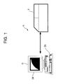
- Fig. 1 is a configurational view of a real time detecting apparatus R according to an embodiment of the invention
- Fig. 2 is an end side view of a reaction detecting apparatus 1 constituting the real time detecting apparatus R shown in Fig. 1
- Fig. 3 is a plan sectional view of the reaction detecting apparatus 1 shown in Fig. 2 .
- the real time detecting apparatus R of the invention includes the reaction detecting apparatus 1 and a processing apparatus C such as a computer for processing detected data from the reaction detecting apparatus 1 in real time.
- the reaction detecting apparatus 1 is an apparatus for proliferating chromosome DNA as reaction samples and detecting a reaction state related to the proliferation by means of an optical measurement method.
- the reaction detecting apparatus 1 includes a body 3 having a reaction chamber 4 formed thereon, and a reaction detecting part 5 that is disposed on the body 3 in the rear of the reaction chamber 4.
- a reaction block 6 made of thermal conductive material such as aluminum.
- the reaction block 6 is provided with a plurality of support holes 8 for supporting a reaction vessel 7 having a plurality of wells 7A... receiving a reactive solution including DNA (target template: ⁇ DNA, etc), reagent, a medium solution, etc.
- the reaction vessel 7 used in this embodiment is a micro plate in which the wells 7A... as 96 (12x8) reaction regions are integrally formed and are connected to respective connection wells (regions other than the wells 7A (reaction regions)).
- the reaction vessel is not limited to a vessel having the integrally formed wells but may be a vessel having a plurality line of tubes.
- the number of wells 7A is not limited to this but may be, for example, 384 for ease handling.
- the wells 7A of the reaction vessel 7 have its opened top side attached with a seal cap 9 for preventing a reaction solution from being evaporated due to temperature treatment of the reaction solution.
- light transmissive synthetic resin material is used for detection of fluorescence strength since the detection can be achieved when light passes through the cap 9.
- a peltier device 10 for heating and cooling the reaction block 6.
- the peltier device 10 is temperature-controlled by a controller (not shown) and heats and cools the reaction block 6 cyclically, thereby cultivating (amplifying) DNA (reaction samples) within the wells 7A of the reaction vessel 7.
- a dark chamber component part 12 is provided in the other end from the reaction detecting part 5 provided on the rear top side of the body 2, that is, over the front top side of the body 2 in which the reaction chamber 4 is formed.
- the front side of the dark chamber component part 12 is forward opened, and the cover 2 inclined low toward the front is provided in this forward opening in a feely opened/closed manner.
- the cover 2 is moveable backward and forward by a rail member 13 formed from the front side of the dark chamber component part 12, that is, the top front side of the body 3 to an inner rear side of the dark chamber component part 12. In a state where the cover 2 is moved backward, the cover 2 is received in the dark chamber component part 12.
- a pressing member 15 for pressing the reaction vessel 7 against the reaction block 6 of the reaction chamber 4 is movably provided to face the reaction block 6, with the cover 2 blocked.
- the pressing member 15 is a plate made of aluminum having good thermal conductivity and is provided with a plurality of transparent holes in correspondence to the top of the wells 7A.
- the Fresnel screen 21 On the top side of the pressing member 15 is disposed a Fresnel screen 21 as an optical lens.
- the Fresnel screen 21 generally has a plurality of grooves which are formed on its plane and reflect and extend incident light. At this time, the Fresnel screen 21 has an optical property to collimate the incident light to be completely or nearly parallelized when the incident light is reflected and extended, thereby allowing the incident light to be transmitted along its optical path corrected for distortion.
- a reflecting plate 22 is disposed on a surface constituting the reaction chamber 4 side of the cover 2 blocking the front top side of the reaction chamber 4 in the top of the reaction block 6.
- the reflecting plate 22 is formed of a flat mirror or the like and serves to reflect light from a light source lamp 23, which will be described in detail later, toward the Fresnel screen 21.
- the reaction detecting part 5 contains the light source lamp 23, a filter unit 35 having a plurality of band pass filters, a reflecting plate 26, a CCD camera 27 and a filter driver 28 for rotating the filter unit 35.
- the light source lamp 23 is a lamp for emitting light including excitation light for exciting fluorescence from a reaction solution depending on the amount of a DNA product to be detected in the reaction solution.
- a halogen lamp is typically used as the light source lamp 23.
- the reflecting plate 26 reflects light having a predetermined wavelength, which is emitted from the light source lamp 23, at a predetermined angle, and polarizes the reflected light t the reflecting plate 22.
- the reflecting plate 26 has a property to transmit predetermined fluorescence. In this embodiment, when the light from the light source lamp 23 disposed in the side of the reaction detecting part 5 is forward reflected by the reflecting plate 26, the reflecting plate 22 is irradiated with the light from the light source lamp 23.
- the filter unit 35 is a unit configured by arranging various kinds of band pass filters in the form of a wheel. This filter unit 35 is rotated by the filter driver 28.
- the band pass filters are selected and positioned between the light source lamp 23 and the reflecting plate 26 or between the reflecting plate 22 and the camera 27.
- a band pass filter 24 is positioned between the light source lamp 23 and the reflecting plate 26 and a band pass filter 25 is positioned between the reflecting plate 22 and the camera 27.
- the band pass filter 24 is an optical filer having a property to pass only light having a wavelength, which is required to excite fluorescence from the reaction solution, of components of the light from the light source lamp 23.
- the light passed the filter 24 becomes excitation light for exciting the fluorescence from a specified component of the reaction solution.
- the band pass filter 25 is an optical filter having a property to pass fluorescence generated from the reaction solution in the wells 7A of the reaction vessel 7 and a predetermined fluorescence component from reflected light through the reflecting plate 22. Here, reflected light components other than the predetermined fluorescence component are intercepted.
- the camera 27 is a device for detecting the fluorescence passed the band pass filter 25.
- a fluorescence image detected by the camera 27 is inputted to the controller and is sent to the processing apparatus C for analysis of concentration, i.e., amount of amplification, of the reaction solution.
- these band pass filers 24 and 25 may be selectively used in any combination thereof based on the reaction solution to be detected and the kind of fluorescence pigment used corresponding to the reaction solution.
- the controller controls the peltier device 10 to set the reaction solution in the reaction vessel 7 supported by the support holes 8 of the reaction block 6 to be, for example, a thermal deformation temperature of +95°C, and then performs a thermal deformation process to thermally deform the reaction solution. Subsequently, the controller controls the peltier device 10 to cool the reaction block 6 to, for example, +60°C, and then performs an annealing process and an expansion process for DNA in the thermally-deformed reaction solution that is received in the reaction vessel 7.
- the controller performs cultivation (amplification) of DNA and the like according a PCR method by repeating one cycle including the thermal deformation process, the annealing process and the expansion process several times, for example, 40 times.
- the reaction detecting part 5 performs a detection operation regularly, such as after one cycle, in order to detect an amplification state of DNA of the reaction solution in the reaction vessel 7.
- a detection operation first, light emitted from the light source lamp 23 reaches the reflecting plate 26 through the band pass filter 24.
- the band pass filter 24 passes only light having a wavelength required to excite fluorescence, that is, excitation light, of the light from the light source lamp 23.
- the reflecting plate 26 reflects the excitation light toward the reflecting plate 22 through the dark chamber component part 12.
- the reflecting plate 22 again reflects the excitation light toward the Fresnel screen 21 provided in the reaction block 6, that is, from the top to the bottom.
- the excitation light impacting on the Fresnel screen 21 is condensed by the lens 21 and is changed in its incident angle to an angle which is parallel or nearly parallel to the wells 7A of the reaction vessel 7 received in the reaction block 6. Accordingly, the excitation light passed the lens 21 is incident into the wells 7A with an incident angle which is parallel or nearly parallel through the transparent holes formed in the pressing member 15.
- the fluorescence and the other reflected light that reached the reflecting plate 22 form an optical path in a substantial horizontal direction within the dark chamber component part 12 by the action of the reflecting plate 22 and reaches the camera 27 through the band pass filter 25 facing the reflecting plate 22.
- the cover 2 is blocked within the dark chamber component part 12, a dark chamber is formed, thereby avoiding attenuation of fluorescence.
- the reflecting plate 26 is made of fluorescence transmissive material, the reflected light and the fluorescence that passes the reflecting plate 26 reaches the band pass filter 25. Only specified fluorescence can be passed through the band pass filter 25 depending on the kind of the filter 25, as described above, only the specified fluorescence can reach the camera 27 disposed in the rear of the filter 25.
- Detection data image data shown in Figs. 4 to 6
- the processing apparatus C analyzes the detection data to detect the concentration of the samples, that is, the amount of amplification of DNA and the like. Since the positional relation between the positions of the wells 7A and the image is known in advance, by obtaining the brightness of pixels of the image of the wells 7A, fluorescence strength of the wells 7A can be measured and the amount of PCR products can be detected from the measured fluorescence strength.
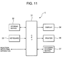
- the processing apparatus C includes an arithmetic processing part (CPU) 31 for performing the detection data sent from the reaction detecting apparatus 1, a storage device (storing means) 32 connected to the arithmetic processing part 31, a keyboard (or input means such as a mouse) 33, a display (output means) 34, a printer (output means) 36, an external storing device 37 such as FD, CD, DVD, memory or the like, etc., as shown in Fig. 11 .
- the detection data sent from the reaction detection apparatus 1 is stored in the storing device 32 and is displayed on the display 34 and so on after being subjected to the following process by the arithmetic processing part 31.
- FIGs. 5 and 6 show images of the detection data sent from the reaction detecting apparatus 1 to the processing apparatus C.
- 96 annular images appearing to be white are fluorescence generated from the PCR products in the wells 7A.
- SYBR Premix Ex Taq registered trademark
- a reaction solution is adjusted from PCR Forward Primer, PCR reverse Primer, Template ( ⁇ DNA given as an initial value) and dH 2 O.
- a reaction solution having the concentration of 0.2 pg/ ⁇ L is divisionally poured in 48 upper half wells 7A (X group) and a reaction solution having the concentration of 0.4 pg/ ⁇ L is divisionally poured in 48 lower half wells 7A (Y group).
- the temperature cycle number is 40.
- the fluorescence strength increases according to the amount of amplification of DNA. Plotting this procedure is the amplification curve of Fig. 7 as described above. This amplification curve is obtained for each well 7A and is displayed on the display 34 ( Fig. 8 ).
- the keyboard (or mouse) 33 is used to set a threshold Th ((11) in Fig. 7 ) in an exponential amplification region ((5) in Fig. 7 )
- cycle number Ct at that point is read to 24.5 in this figure. Since there is a correlation between the threshold cycle number Ct and the initial amount of DNA of a test sample, a calibration curve representing this linear relation can be prepared.
- the arithmetic processing part 31 estimates the initial amount of DNA of the test sample based on this calibration. This enables correct quantitativeness based on a PCR amplification speed theory.
- the brightness of pixels in the image data obtained by the camera 27 of the reaction detecting apparatus 1 is not necessarily constant and there occurs a spot due to contamination of the optical system or way-out light as indicated by (1) in Fig. 4 .
- this spot overlaps with the images of the wells 7A as shown in Fig. 5 , wastefully adding to the fluorescence strength of the wells 7A.
- the arithmetic processing part 31 of the processing apparatus C performs the following process in order to obtain the original fluorescence strength of the wells. That is, for example, in case of a well 7A lying in a stage (B11) second from the right side and second from the top side in Fig. 6 , a fluorescence measurement value [DNA]rawB11 of the well 7A ((4) in Fig. 6 ) of the B11 stage is measured and stored in the storing device 32.
- This process is performed for all 96 wells every detection of the fluorescence measurement value [DNA]raw to determine the original fluorescence strength [DNA]real of all wells 7A.
- it is possible to obtain the original fluorescence strength [DNA]real of the DNA product of the well 7A except for the fluorescence measurement value [DNA]bg of the background by errors or contamination of the well 7A and its circumferences and way-out light for each well 7A (reaction region).
- the present invention is not limited to this but the average value may be one point value or an average value of two or three points.
- the 4 point average value is used as in this embodiment, it is possible to calculate more correct fluorescence strength of the background to determine the fluorescence strength [DNA]real with higher precision.
- a simple average of the 4 point fluorescence measurement values near the well 7A is used in this embodiment, the present invention is not limited to this, but points may be weighted and averaged in consideration of spots of contamination conditions.
- Fig. 8 shows DNA amplification curves of all 96 wells 7A.
- a horizontal axis represents temperature cycle number and a vertical axis represents fluorescence strength.
- the amplification curve of each well 7A may be unbalanced and a plurality of threshold cycle numbers Ct may occurs as indicated by (8) and (9) in Fig. 8 (unbalance).
- the arithmetic processing part 31 normalizes data based on a predetermined selection command from the keyboard (or mouse) 33. That is, the arithmetic processing part 31 obtains fluorescence strength [DNA]nN normalized by the following Equation (3) using the fluorescence strength [DNA]n (the original fluorescence strength [DNA]real at an n-th temperature cycle number) determined every temperature cycle numbers n and stored in the storing device 32, the fluorescence strength maximum value [DNA]max (the maximum of fluorescence strengths [DNA]real up to the temperature cycle numbers n, this is stored in the storing device 32) for each well 7A, and a value Z common to wells 7A (all wells 7A in this embodiment) to be compared.
- [ DNA ] nN [ DNA ] n / [ DNA ] max + z
- Fig. 9 shows multiplication of [DNA]nN by a value common to all wells in order to set the whole scale to be a proper value.
- the fluorescence strength in a plateau region in the late of cycle may be unbalanced due to unbalance of chemical reaction in addition to the above-mentioned apparatus error factors. It is believed that such a chemical reaction factor has no proportional effect on the fluorescence strength in an exponential amplification region. That is, in some cases, fluorescence strengths in regions having the plateau effect had better not to be completely matched each other.
- the Z value may be determined according to the following Equation (4).
- Z ⁇ [ DNA ] max + ⁇
- ⁇ and ⁇ are coefficients common to the wells 7A.
- the arithmetic processing part 31 calculates the above-described maximum value [DNA]max as a moving average of fluorescence strengths. This is because the fluorescence strength [DNA]real shows a saw shape actually.
- the maximum value used for the normalization may be a peak value of the saw shape or, for example, 90% of the peak value (either being related to the maximum value).
- (10) in Fig. 8 is a region of a level at which a reaction result can not be detected at the initial stage of cycle
- the arithmetic processing part 31 corrects a baseline based on an instruction from the keyboard (or mouse) 33. That is, the arithmetic processing part 31 sets an average value [DNA]base of the fluorescence strengths of the well 7A in the region 10 at the initial stage of cycle to be a baseline and performs the above-described normalization process after subtracting the average value from the above-mentioned [DNA]n and [DNA]max.
- the reason for this process is that the initial fluorescence strength is set to be zero in Figs. 9 and 10 ([DNA]base may use the minimum value of [DNA]n).
Landscapes
- Chemical & Material Sciences (AREA)
- Life Sciences & Earth Sciences (AREA)
- Health & Medical Sciences (AREA)
- Organic Chemistry (AREA)
- Engineering & Computer Science (AREA)
- Zoology (AREA)
- Wood Science & Technology (AREA)
- Bioinformatics & Cheminformatics (AREA)
- General Health & Medical Sciences (AREA)
- Biochemistry (AREA)
- Biotechnology (AREA)
- Genetics & Genomics (AREA)
- Analytical Chemistry (AREA)
- General Engineering & Computer Science (AREA)
- Physics & Mathematics (AREA)
- Proteomics, Peptides & Aminoacids (AREA)
- Microbiology (AREA)
- Immunology (AREA)
- Chemical Kinetics & Catalysis (AREA)
- Biophysics (AREA)
- Molecular Biology (AREA)
- Biomedical Technology (AREA)
- General Physics & Mathematics (AREA)
- Nuclear Medicine, Radiotherapy & Molecular Imaging (AREA)
- Pathology (AREA)
- Medicinal Chemistry (AREA)
- Sustainable Development (AREA)
- Plant Pathology (AREA)
- Investigating, Analyzing Materials By Fluorescence Or Luminescence (AREA)
- Apparatus Associated With Microorganisms And Enzymes (AREA)
- Measuring Or Testing Involving Enzymes Or Micro-Organisms (AREA)
Abstract
Description
- This invention relates to an apparatus for real-time detecting a polynucleotide product obtained from a polymerase chain reaction (PCR).
- A PCR is a cyclic enzyme reaction to replicate a DNA chain. As the PCR is used as a template of a cycle in which PCR products (nucleic acid amplification products) replicated in previous cycles are consecutive, arrayed target molecules can be exponentially amplified. A real time PCR is to excite fluorescent material by irradiating a PCR product with excitation light using, for example, array-specific probes (TaqMan probes) marked with two different kinds of fluorescent pigments interfering with each other, measure the strength of the fluorescence and monitor amplification of the PCR products in real time.
- In quantitative use, a threshold ((6) in
Fig. 7 ) is set in an exponential amplification region of an amplification curve for existing samples, and a point (threshold cycle number (Ct). (8) inFig. 8 ) at which the threshold intersects the amplification curve is calculated. There is a linear relation between the threshold cycle number (Ct) and the initial amount of DNA of a test sample measured in terms of log value, and a calibration curve representing this linear relation can be prepared. The initial amount of DNA of the test sample is estimated based on the calibration curve. This enables correct quantitativeness based on a PCR amplification speed theory. - Here, since an actual PCR efficiency is not 100%, the concentration of an amplified PCR product is expressed by the following
Equation 1.
- [DNA] : Concentration of PCR product
- [DNA]
- 0 : Initial concentration of target Template
- e : Average PCR efficiency
- c : Cycle number
- That is, if the average PCR efficiency (e) is 100% (i.e., e=1 in the above Equation (1)), although the concentration [DNA] of the PCR product is exponentially amplified with 2c, since the efficiency (e) is slowly lowered from the initial stage, through the middle stage, to the late state of the cycle, an amplification curve is as shown in
Fig. 7 . InFig. 7 , a horizontal axis represents the cycle number and a vertical axis represents the fluorescence strength. As shown in the figure, the fluorescence strength is exponentially amplified ((5) inFig. 7 ) at the cycle initial stage, linearly amplified ((6) inFig. 7 ) at the cycle middle stage, and not amplified ((7) inFig. 7 ) by a plateau effect at the cycle late stage. - Chemical-reactive factors for this plateau effect are as follows.
- Hydrolysis of dNTP and primer
- Deactivation of DNA polymerase (DNA synthase to make a copy of a template (cast)) by heat.
- Lowering of primer annealing efficiency by reassociation of one chain PCR fragment
- Competitive material by non-specific PCR product
- Accumulation of PCR inhabitation material such as pyrophosphate
- Hydrolysis of PCR product by exonuclease activation of DNA polymerase
- Accordingly, the measurement in the exponential amplification region satisfying the relation of the Equation (1) is a precondition for the real time PCR (see Patent Document 1)
- [Patent Document 1] Japanese Patent Application Publication No.
2005-516630 - [Patent Document 2] Japanese Patent No.
2909216 - As a reactive vessel used for the real time PCR, a vessel called a micro plate having a plurality (for example, 96) of wells (reactive regions constituted by concave portions) is being used in common and reactive solution having a predetermined initial DNA concentration is divisionally poured in the wells. However, an amplification curve for each of the wells of the reactive vessel becomes unbalanced due to the following apparatus error factors
- Error of optical system
- Concentration error of correction solution
- Divisional pour error of correction solution
- Light transmission error of cap of reactive vessel or seal film
- Contamination error of reactive vessel
- Divisional pour error of reactive vessel
- Here, the reactive vessel mainly uses a cheap method in which the above-mentioned seal film with an adhesive is attached to the entire region of a single side and the wells are cover by a cap. In addition, the wells are irradiated with excitation light through the seal film and fluorescence generated from the PCR product (reaction product) is detected by a light detecting part such as a CCD camera through the seal film (these components constitute an optical system). In this manner, although the seal film and the body of the reactive vessel constitute important factors of the optical system in measurement of the fluorescence strength, these components are consumable parts, it is difficult to expect optical performance with high uniformity and precision.
-
Fig. 4 shows an actual image of a reactive vessel before PCR, which is detected by an optical detecting part. While the circumference of wells of the reactive vessel appears to be black as a whole, the brightness of pixels of the image as a background is not necessarily constant and there occurs a spot due to contamination of the optical system or way-out light as indicated by (1) in the figure. When a PCR reaction is initiated, this spot overlaps with images (96 images appearing to be round inFig. 5 ) of the wells as indicated by (2) inFig. 5 , wastefully adding to the fluorescence strength of the wells. - So, in the prior art, empty reactive vessels containing no DNA are initially prepared, and fluorescence strengths for wells are measured in such an empty state and are stored as standard correction values. Then, by performing a correcting process in which the stored correction values are subtracted from measurement values of actual fluorescence strengths, such correction of the optical system is performed. However, since errors due to contamination of the empty reactive vessels are inherent to the respective reactive vessels, if correction values by other standard empty reactive vessels are used, there occurs a problem of errors in measurement values.
- In addition, in
Patent Document 2, although a first fluorescence signal is corrected with a second fluorescence signal, since a solution that generates second fluorescence for reference must be added to a solution that generates first fluorescence to be originally measured, work becomes complicated and costs are raised. In addition, the solution that generates the second fluorescence can not give any effect if it can not be divisionally poured and measured with very high precision. In addition, since an especial optical filter has to be used to measure the second fluorescence and has to be exchanged for the solution that generates the first fluorescence and the solution that generates the second fluorescence every measurement, there is a problem that it takes extra time to acquire and process data. - The present invention has made to overcome the above technical problems and it is an object of the invention to provide an apparatus for detecting a nucleic acid amplification product in real time, which is capable of effectively excluding or reducing apparatus error factors without using a second fluorescence signal used for correction.
- According to a first aspect of the invention, there is provided an apparatus for detecting fluorescence strength from a nucleic acid amplification product in each of a plurality of reaction regions given with temperature cycles in real time, wherein a fluorescence measurement value [DNA]raw obtained from the reaction region and a fluorescence measurement value [DNA]bg obtained from regions other than the reaction region adjacent to the reaction region are detected, and the fluorescence measurement value [DNA]bg is subtracted from the fluorescence measurement value [DNA]raw to determine fluorescence strength [DNA]real of the reaction region.
- According to a second aspect of the invention, the fluorescence measurement value [DNA]bg is a simple average value of fluorescence measurement values obtained from the regions other than the plurality of reaction regions adjacent to the reaction region, or an average value of fluorescence measurement values after the fluorescence measurement values are weighted.
- According to a third aspect of the invention, the fluorescence measurement value [DNA]bg is detected every detection of the fluorescence measurement value [DNA]raw, and the fluorescence measurement value [DNA]bg is subtracted from the fluorescence measurement value [DNA]raw to determine the fluorescence strength [DNA]real.
- According to a fourth aspect of the invention, there is provided an apparatus for detecting fluorescence strength from a nucleic acid amplification product in each of a plurality of reaction regions given with temperature cycles in real time, wherein fluorescence strengths [DNA]n obtained from the reaction regions every temperature cycles n are normalized using the maximum value of the fluorescence strengths [DNA]n or related value [DNA]max, and a threshold cycle number Ct is calculated by setting a threshold Th in an exponential amplification region of an amplification curve drawn using a normalized fluorescence strength [DNA]nN.
- According to a fifth aspect of the invention, the fluorescence strength [DNA]nN is calculated by dividing the fluorescence strength [DNA]n for each reaction region by a value obtained by adding a value common to the reaction regions to be compared to the maximum value or related value [DNA]max.
- According to a sixth aspect of the invention, the amplification curve is drawn after fluorescence strength [DNA]base before the exponential amplification region is subtracted from the fluorescence strength [DNA]n for each reaction region and the maximum value or related value [DNA]max.
- According to the first aspect of the invention, in the apparatus for detecting fluorescence strength from a nucleic acid amplification product in each of a plurality of reaction regions given with temperature cycles in real time, since a fluorescence measurement value [DNA]raw obtained from the reaction region and a fluorescence measurement value [DNA]bg obtained from regions other than the reaction region adjacent to the reaction region are detected, and the fluorescence measurement value [DNA]bg is subtracted from the fluorescence measurement value [DNA]raw to determine fluorescence strength [DNA]real of the reaction region, it is possible to obtain the original fluorescence strength [DNA]real of the DNA product of the reaction region except for the fluorescence measurement value of a background by errors or contamination of the reaction region and its circumferences and way-out light for each reaction region. Accordingly, it is possible to realize preparation and quantitativeness of a correct amplification curve. In this case, with no need to use the second fluorescence signal in the prior art, it is possible to reduce time taken to acquire and process data without increase of costs and deterioration of workability.
- According to the second aspect of the invention, in addition to the first aspect, since the fluorescence measurement value [DNA]bg is a simple average value of fluorescence measurement values obtained from the regions other than the plurality of reaction regions adjacent to the reaction region, or an average value of fluorescence measurement values after the fluorescence measurement values are weighted, it is possible to calculate more correct fluorescence strength of the background to determine the fluorescence strength [DNA]real with higher precision.
- According to the third aspect of the invention, in addition to the first aspect or the second aspect, since the fluorescence measurement value [DNA]bg is detected every detection of the fluorescence measurement value [DNA]raw, and the fluorescence measurement value [DNA]bg is subtracted from the fluorescence measurement value [DNA]raw to determine the fluorescence strength [DNA]real, although the fluorescence strength of the background is varied during reaction, it is possible to always obtain the original fluorescence strength [DNA]real of the DNA product in real time with high precision.
- According to the fourth aspect of the invention, in the apparatus for detecting fluorescence strength from a nucleic acid amplification product in each of a plurality of reaction regions given with temperature cycles in real time, since fluorescence strengths [DNA]n obtained from the reaction regions every temperature cycles n are normalized using the maximum value of the fluorescence strengths [DNA]n or related value [DNA]max, and a threshold cycle number Ct is calculated by setting a threshold Th in an exponential amplification region of an amplification curve drawn using a normalized fluorescence strength [DNA]nN, it is possible to correct and reduce unbalance of the fluorescence strength of each reaction region due to the apparatus error factors such as optical system errors, correction solution concentration errors, correction solution divisional pour errors, reaction solution divisional pour errors, etc., thereby enabling calculation of threshold cycle numbers Ct with high reliability.
- According to the fifth aspect of the invention, in addition to the fourth aspect, since the fluorescence strength [DNA]nN is calculated by dividing the fluorescence strength [DNA]n for each reaction region by a value obtained by adding a value common to the reaction regions to be compared to the maximum value or related value [DNA]max, behavior of data occurring due to factors other than the apparatus error factors can be easily grasped by approximating amplification curves from the middle stage and the late stage of the cycle to actual data while suppressing the normalization effect and sufficiently securing the correction effect at the threshold.
- According to the sixth aspect of the invention, in addition to the fourth aspect or the fifth aspect, since the amplification curve is drawn after fluorescence strength [DNA]base before the exponential amplification region is subtracted from the fluorescence strength [DNA]n for each reaction region and the maximum value or related value [DNA]max, it is possible to grasp the situation of the fluorescence strength from the PCR product itself, excluding the fluorescence strength generated from the reaction solution itself in the reaction region.
- [0066]
-
Fig. 1 is a configurational view of a real time detecting apparatus according to an embodiment of the invention. -
Fig. 2 is an end side view of a reaction detecting apparatus constituting the real time detecting apparatus shown inFig. 1 . -
Fig. 3 is a plan sectional view of the reaction detecting apparatus shown inFig. 2 . -
Fig. 4 is a view showing a fluorescence strength state of a background of a reaction vessel. -
Fig. 5 is a view showing a fluorescence strength state after reaction. -
Fig. 6 is a view showing another fluorescence strength state after reaction. -
Fig. 7 shows a DNA amplification curve of a well. -
Fig. 8 shows DNA amplification curves of all wells. -
Fig. 9 shows a DNA amplification curve when the data ofFig. 8 are normalized. -
Fig. 10 shows a DNA amplification curve when the data ofFig. 8 are incompletely normalized. -
Fig. 11 is a functional block diagram of a processing apparatus constituting the real time detecting apparatus shown inFig. 1 . - Hereinafter embodiments of the present invention will be described in detail with reference to the drawings.
-
Fig. 1 is a configurational view of a real time detecting apparatus R according to an embodiment of the invention,Fig. 2 is an end side view of areaction detecting apparatus 1 constituting the real time detecting apparatus R shown inFig. 1 , andFig. 3 is a plan sectional view of thereaction detecting apparatus 1 shown inFig. 2 . The real time detecting apparatus R of the invention includes thereaction detecting apparatus 1 and a processing apparatus C such as a computer for processing detected data from thereaction detecting apparatus 1 in real time. - In this embodiment, the
reaction detecting apparatus 1 is an apparatus for proliferating chromosome DNA as reaction samples and detecting a reaction state related to the proliferation by means of an optical measurement method. Thereaction detecting apparatus 1 includes abody 3 having areaction chamber 4 formed thereon, and areaction detecting part 5 that is disposed on thebody 3 in the rear of thereaction chamber 4. Within thereaction chamber 4 is provided areaction block 6 made of thermal conductive material such as aluminum. Thereaction block 6 is provided with a plurality ofsupport holes 8 for supporting areaction vessel 7 having a plurality of wells 7A... receiving a reactive solution including DNA (target template: λDNA, etc), reagent, a medium solution, etc. - The
reaction vessel 7 used in this embodiment is a micro plate in which the wells 7A... as 96 (12x8) reaction regions are integrally formed and are connected to respective connection wells (regions other than the wells 7A (reaction regions)). The reaction vessel is not limited to a vessel having the integrally formed wells but may be a vessel having a plurality line of tubes. The number of wells 7A is not limited to this but may be, for example, 384 for ease handling. The wells 7A of thereaction vessel 7 have its opened top side attached with aseal cap 9 for preventing a reaction solution from being evaporated due to temperature treatment of the reaction solution. In this embodiment, light transmissive synthetic resin material is used for detection of fluorescence strength since the detection can be achieved when light passes through thecap 9. - Within the
body 2 is provided apeltier device 10 for heating and cooling thereaction block 6. Thepeltier device 10 is temperature-controlled by a controller (not shown) and heats and cools thereaction block 6 cyclically, thereby cultivating (amplifying) DNA (reaction samples) within the wells 7A of thereaction vessel 7. - In this embodiment, a dark
chamber component part 12 is provided in the other end from thereaction detecting part 5 provided on the rear top side of thebody 2, that is, over the front top side of thebody 2 in which thereaction chamber 4 is formed. The front side of the darkchamber component part 12 is forward opened, and thecover 2 inclined low toward the front is provided in this forward opening in a feely opened/closed manner. Thecover 2 is moveable backward and forward by arail member 13 formed from the front side of the darkchamber component part 12, that is, the top front side of thebody 3 to an inner rear side of the darkchamber component part 12. In a state where thecover 2 is moved backward, thecover 2 is received in the darkchamber component part 12. - Within the
cover 2, a pressingmember 15 for pressing thereaction vessel 7 against thereaction block 6 of thereaction chamber 4 is movably provided to face thereaction block 6, with thecover 2 blocked. The pressingmember 15 is a plate made of aluminum having good thermal conductivity and is provided with a plurality of transparent holes in correspondence to the top of the wells 7A. - On the top side of the pressing
member 15 is disposed aFresnel screen 21 as an optical lens. TheFresnel screen 21 generally has a plurality of grooves which are formed on its plane and reflect and extend incident light. At this time, theFresnel screen 21 has an optical property to collimate the incident light to be completely or nearly parallelized when the incident light is reflected and extended, thereby allowing the incident light to be transmitted along its optical path corrected for distortion. - In the meantime, a reflecting
plate 22 is disposed on a surface constituting thereaction chamber 4 side of thecover 2 blocking the front top side of thereaction chamber 4 in the top of thereaction block 6. In this embodiment, the reflectingplate 22 is formed of a flat mirror or the like and serves to reflect light from alight source lamp 23, which will be described in detail later, toward theFresnel screen 21. - In the meantime, the
reaction detecting part 5 contains thelight source lamp 23, afilter unit 35 having a plurality of band pass filters, a reflectingplate 26, aCCD camera 27 and afilter driver 28 for rotating thefilter unit 35. - The
light source lamp 23 is a lamp for emitting light including excitation light for exciting fluorescence from a reaction solution depending on the amount of a DNA product to be detected in the reaction solution. A halogen lamp is typically used as thelight source lamp 23. The reflectingplate 26 reflects light having a predetermined wavelength, which is emitted from thelight source lamp 23, at a predetermined angle, and polarizes the reflected light t the reflectingplate 22. The reflectingplate 26 has a property to transmit predetermined fluorescence. In this embodiment, when the light from thelight source lamp 23 disposed in the side of thereaction detecting part 5 is forward reflected by the reflectingplate 26, the reflectingplate 22 is irradiated with the light from thelight source lamp 23. - The
filter unit 35 is a unit configured by arranging various kinds of band pass filters in the form of a wheel. Thisfilter unit 35 is rotated by thefilter driver 28. The band pass filters are selected and positioned between thelight source lamp 23 and the reflectingplate 26 or between the reflectingplate 22 and thecamera 27. In the figure, aband pass filter 24 is positioned between thelight source lamp 23 and the reflectingplate 26 and aband pass filter 25 is positioned between the reflectingplate 22 and thecamera 27. - The
band pass filter 24 is an optical filer having a property to pass only light having a wavelength, which is required to excite fluorescence from the reaction solution, of components of the light from thelight source lamp 23. The light passed thefilter 24 becomes excitation light for exciting the fluorescence from a specified component of the reaction solution. - The
band pass filter 25 is an optical filter having a property to pass fluorescence generated from the reaction solution in the wells 7A of thereaction vessel 7 and a predetermined fluorescence component from reflected light through the reflectingplate 22. Here, reflected light components other than the predetermined fluorescence component are intercepted. - The
camera 27 is a device for detecting the fluorescence passed theband pass filter 25. A fluorescence image detected by thecamera 27 is inputted to the controller and is sent to the processing apparatus C for analysis of concentration, i.e., amount of amplification, of the reaction solution. In addition, theseband pass filers - With the above configuration, the controller controls the
peltier device 10 to set the reaction solution in thereaction vessel 7 supported by the support holes 8 of thereaction block 6 to be, for example, a thermal deformation temperature of +95°C, and then performs a thermal deformation process to thermally deform the reaction solution. Subsequently, the controller controls thepeltier device 10 to cool thereaction block 6 to, for example, +60°C, and then performs an annealing process and an expansion process for DNA in the thermally-deformed reaction solution that is received in thereaction vessel 7. The controller performs cultivation (amplification) of DNA and the like according a PCR method by repeating one cycle including the thermal deformation process, the annealing process and the expansion process several times, for example, 40 times. - During or after this cultivation, the
reaction detecting part 5 performs a detection operation regularly, such as after one cycle, in order to detect an amplification state of DNA of the reaction solution in thereaction vessel 7. In the detection operation, first, light emitted from thelight source lamp 23 reaches the reflectingplate 26 through theband pass filter 24. Theband pass filter 24 passes only light having a wavelength required to excite fluorescence, that is, excitation light, of the light from thelight source lamp 23. The reflectingplate 26 reflects the excitation light toward the reflectingplate 22 through the darkchamber component part 12. The reflectingplate 22 again reflects the excitation light toward theFresnel screen 21 provided in thereaction block 6, that is, from the top to the bottom. - The excitation light impacting on the
Fresnel screen 21 is condensed by thelens 21 and is changed in its incident angle to an angle which is parallel or nearly parallel to the wells 7A of thereaction vessel 7 received in thereaction block 6. Accordingly, the excitation light passed thelens 21 is incident into the wells 7A with an incident angle which is parallel or nearly parallel through the transparent holes formed in the pressingmember 15. - When the DNA in the well 7A beforehand added with predetermined fluorescence pigment is irradiated with the excitation light incident at the parallel or nearly parallel angle in the wells 7A, fluorescence is generated depending on the amount of PCR product. The generated fluorescence and other reflected light from the PCR product reach the reflecting
plate 22 through the transparent holes formed in the pressingmember 15 formed in the pressingmember 15 and theFresnel screen 21 as well. - Thereafter, the fluorescence and the other reflected light that reached the reflecting
plate 22 form an optical path in a substantial horizontal direction within the darkchamber component part 12 by the action of the reflectingplate 22 and reaches thecamera 27 through theband pass filter 25 facing the reflectingplate 22. In this case, since thecover 2 is blocked within the darkchamber component part 12, a dark chamber is formed, thereby avoiding attenuation of fluorescence. - At this time, since the reflecting
plate 26 is made of fluorescence transmissive material, the reflected light and the fluorescence that passes the reflectingplate 26 reaches theband pass filter 25. Only specified fluorescence can be passed through theband pass filter 25 depending on the kind of thefilter 25, as described above, only the specified fluorescence can reach thecamera 27 disposed in the rear of thefilter 25. - When the
camera 27 take an image of the received fluorescence, a fluorescence state of the PCR products in the wells 7A of thereaction vessel 7 is detected. Detection data (image data shown inFigs. 4 to 6 ) on the detected fluorescence state of the PCR products are sent from the controller to the processing apparatus C. The processing apparatus C analyzes the detection data to detect the concentration of the samples, that is, the amount of amplification of DNA and the like. Since the positional relation between the positions of the wells 7A and the image is known in advance, by obtaining the brightness of pixels of the image of the wells 7A, fluorescence strength of the wells 7A can be measured and the amount of PCR products can be detected from the measured fluorescence strength. - The processing apparatus C includes an arithmetic processing part (CPU) 31 for performing the detection data sent from the
reaction detecting apparatus 1, a storage device (storing means) 32 connected to thearithmetic processing part 31, a keyboard (or input means such as a mouse) 33, a display (output means) 34, a printer (output means) 36, anexternal storing device 37 such as FD, CD, DVD, memory or the like, etc., as shown inFig. 11 . The detection data sent from thereaction detection apparatus 1 is stored in thestoring device 32 and is displayed on thedisplay 34 and so on after being subjected to the following process by thearithmetic processing part 31. - Next, a process sequence of the detection data in the processing apparatus C will be described.
Figs. 5 and6 show images of the detection data sent from thereaction detecting apparatus 1 to the processing apparatus C. 96 annular images appearing to be white are fluorescence generated from the PCR products in the wells 7A. In this embodiment, with SYBR Premix Ex Taq (registered trademark) as a base, a reaction solution is adjusted from PCR Forward Primer, PCR reverse Primer, Template (λDNA given as an initial value) and dH2O. InFigs. 5 and6 , a reaction solution having the concentration of 0.2 pg/µL is divisionally poured in 48 upper half wells 7A (X group) and a reaction solution having the concentration of 0.4 pg/µL is divisionally poured in 48 lower half wells 7A (Y group). The temperature cycle number is 40. - When the temperature cycle number progresses from reaction initiation, the fluorescence strength increases according to the amount of amplification of DNA. Plotting this procedure is the amplification curve of
Fig. 7 as described above. This amplification curve is obtained for each well 7A and is displayed on the display 34 (Fig. 8 ). When the keyboard (or mouse) 33 is used to set a threshold Th ((11) inFig. 7 ) in an exponential amplification region ((5) inFig. 7 ), cycle number Ct at that point (threshold cycle number Ct) is read to 24.5 in this figure. Since there is a correlation between the threshold cycle number Ct and the initial amount of DNA of a test sample, a calibration curve representing this linear relation can be prepared. Thearithmetic processing part 31 estimates the initial amount of DNA of the test sample based on this calibration. This enables correct quantitativeness based on a PCR amplification speed theory. - As described above, before the reaction initiation, the brightness of pixels in the image data obtained by the
camera 27 of thereaction detecting apparatus 1 is not necessarily constant and there occurs a spot due to contamination of the optical system or way-out light as indicated by (1) inFig. 4 . When the PCR reaction is progressed, this spot overlaps with the images of the wells 7A as shown inFig. 5 , wastefully adding to the fluorescence strength of the wells 7A. - So, the
arithmetic processing part 31 of the processing apparatus C performs the following process in order to obtain the original fluorescence strength of the wells. That is, for example, in case of a well 7A lying in a stage (B11) second from the right side and second from the top side inFig. 6 , a fluorescence measurement value [DNA]rawB11 of the well 7A ((4) inFig. 6 ) of the B11 stage is measured and stored in thestoring device 32. Next, 4 adjacent fluorescence measurement values [DNA]bg1, [DNA]bg2, [DNA]bg3 and [DNA]bg4 in a connection wall portion near the well 7A of the B11 stage are measured and an average value of the 4 fluorescence measurement values (a fluorescence measurement value of a background) is obtained and stored in thestoring device 32. Then, according to the following Equation (2), by subtracting the average value from the fluorescence measurement value [DNA]rawB11, the original fluorescence strength [DNA]realB1 of the well 7A of the B11 stage is calculated.
- This process is performed for all 96 wells every detection of the fluorescence measurement value [DNA]raw to determine the original fluorescence strength [DNA]real of all wells 7A. Thus, it is possible to obtain the original fluorescence strength [DNA]real of the DNA product of the well 7A except for the fluorescence measurement value [DNA]bg of the background by errors or contamination of the well 7A and its circumferences and way-out light for each well 7A (reaction region).
- Accordingly, it is possible to realize preparation and quantitativeness of a correct amplification curve. In this case, with no need to use the second fluorescence signal in the prior art, since an arithmetic process may have only to be performed in the processing apparatus C, it is possible to reduce time taken to acquire and process data without increase of costs and deterioration of workability.
- In this embodiment, although the 4 adjacent fluorescence measurement values [DNA]bg1, [DNA]bg2, [DNA]bg3 and [DNA]bg4 near the well 7A are measured and their average value is subtracted from the fluorescence measurement value [DNA]raw, the present invention is not limited to this but the average value may be one point value or an average value of two or three points. However, when the 4 point average value is used as in this embodiment, it is possible to calculate more correct fluorescence strength of the background to determine the fluorescence strength [DNA]real with higher precision. In addition, although a simple average of the 4 point fluorescence measurement values near the well 7A is used in this embodiment, the present invention is not limited to this, but points may be weighted and averaged in consideration of spots of contamination conditions.
- Variation (drift) of the fluorescence strength of the background before and after reaction is not clear. However, in this embodiment, since the fluorescence measurement values [DNA]bg1 to [DNA]bg4 are detected every detection of the fluorescence measurement value [DNA]raw and the average value of the fluorescence measurement values [DNA]bg1 to [DNA]bg4 is subtracted from the fluorescence measurement value [DNA]raw to determine the fluorescence strength [DNA]real, although the fluorescence strength of the background is varied during reaction, it is possible to always obtain the original fluorescence strength [DNA]real of the DNA product in real time with high precision.
- Next,
Fig. 8 shows DNA amplification curves of all 96 wells 7A. In the figure, a horizontal axis represents temperature cycle number and a vertical axis represents fluorescence strength. As described above, since the reaction solutions having different concentrations divided into the upper half X group and the lower half Y group inFigs. 5 and6 are divisionally poured, a reaction curve have to appear as two lines originally. In addition, the threshold cycle number Ct will also be two. However, due to apparatus error factors such as the above-mentioned optical system errors, correction solution concentration errors, correction solution divisional pour errors, reaction solution divisional pour errors, etc., the amplification curve of each well 7A may be unbalanced and a plurality of threshold cycle numbers Ct may occurs as indicated by (8) and (9) inFig. 8 (unbalance). - So, the
arithmetic processing part 31 normalizes data based on a predetermined selection command from the keyboard (or mouse) 33. That is, thearithmetic processing part 31 obtains fluorescence strength [DNA]nN normalized by the following Equation (3) using the fluorescence strength [DNA]n (the original fluorescence strength [DNA]real at an n-th temperature cycle number) determined every temperature cycle numbers n and stored in thestoring device 32, the fluorescence strength maximum value [DNA]max (the maximum of fluorescence strengths [DNA]real up to the temperature cycle numbers n, this is stored in the storing device 32) for each well 7A, and a value Z common to wells 7A (all wells 7A in this embodiment) to be compared.
- By this process, the fluorescence strength of each well 7A is normalized.
Fig. 9 shows a case of Z=0. Since unbalance of the fluorescence strength due to the apparatus error factors of each well 7A is corrected and reduced by this normalization, unbalance of the threshold cycle numbers Ct in the X group and the Y group can be further reduced as compared toFig. 8 . This enables calculation of threshold cycle numbers with high reliability. In addition,Fig. 9 shows multiplication of [DNA]nN by a value common to all wells in order to set the whole scale to be a proper value. - Here, the fluorescence strength in a plateau region in the late of cycle may be unbalanced due to unbalance of chemical reaction in addition to the above-mentioned apparatus error factors. It is believed that such a chemical reaction factor has no proportional effect on the fluorescence strength in an exponential amplification region. That is, in some cases, fluorescence strengths in regions having the plateau effect had better not to be completely matched each other.
- In this case, the keyboard (or mouse) 33 is used to increase the Z value of the above Equation (3).
Fig. 10 shows amplification curves for wells 7A in case of Z=20000. Increase of the Z value means weakening of the normalization effect. However, it can be seen fromFig. 10 that behavior of the amplification curves from the middle stage to the late state of the cycle approximates to behavior of actual fluorescence strength (seeFig. 8 ). In the meantime, it can be seen from this figure that the correction effect at the threshold is sufficiently secured. Accordingly, by approximating the amplification curves from the middle stage and the late stage of the cycle to actual data while suppressing the normalization effect and sufficiently securing the correction effect at the threshold, behavior of data occurring due to factors other than the apparatus error factors can be easily grasped. - Here, when such incomplete normalization is made, the Z value may be determined according to the following Equation (4).

In addition, thearithmetic processing part 31 calculates the above-described maximum value [DNA]max as a moving average of fluorescence strengths. This is because the fluorescence strength [DNA]real shows a saw shape actually. However, the maximum value used for the normalization may be a peak value of the saw shape or, for example, 90% of the peak value (either being related to the maximum value). - Here, although (10) in
Fig. 8 is a region of a level at which a reaction result can not be detected at the initial stage of cycle, since the reaction solution itself in the wells 7A initially generates predetermined fluorescence, the fluorescence strength is not generally zero in this region. So, thearithmetic processing part 31 corrects a baseline based on an instruction from the keyboard (or mouse) 33. That is, thearithmetic processing part 31 sets an average value [DNA]base of the fluorescence strengths of the well 7A in theregion 10 at the initial stage of cycle to be a baseline and performs the above-described normalization process after subtracting the average value from the above-mentioned [DNA]n and [DNA]max. The reason for this process is that the initial fluorescence strength is set to be zero inFigs. 9 and 10 ([DNA]base may use the minimum value of [DNA]n). - Accordingly, it is possible to grasp the situation of the fluorescence strength from the PCR product itself, excluding the fluorescence strength generated from the reaction solution itself in the wells 7A.
- It should be understood that material, amount and number shown in this embodiment are not particularly limited.
Claims (6)
- An apparatus for detecting fluorescence strength from a nucleic acid amplification product in each of a plurality of reaction regions given with temperature cycles in real time,
wherein a fluorescence measurement value [DNA]raw obtained from the reaction region and a fluorescence measurement value [DNA]bg obtained from regions other than the reaction region adjacent to the reaction region are detected, and the fluorescence measurement value [DNA]bg is subtracted from the fluorescence measurement value [DNA]raw to determine fluorescence strength [DNA]real of the reaction region. - The apparatus according to Claim 1,
wherein the fluorescence measurement value [DNA]bg is a simple average value of fluorescence measurement values obtained from the regions other than the plurality of reaction regions adjacent to the reaction region, or an average value of fluorescence measurement values after the fluorescence measurement values are weighted. - The apparatus according to Claim 1 or 2,
wherein the fluorescence measurement value [DNA]bg is detected every detection of the fluorescence measurement value [DNA]raw, and the fluorescence measurement value [DNA]bg is subtracted from the fluorescence measurement value [DNA]raw to determine the fluorescence strength [DNA]real. - An apparatus for detecting fluorescence strength from a nucleic acid amplification product in each of a plurality of reaction regions given with temperature cycles in real time,
wherein fluorescence strengths [DNA]n obtained from the reaction regions every temperature cycles n are normalized using the maximum value of the fluorescence strengths [DNA]n or related value [DNA]max, and a threshold cycle number Ct is calculated by setting a threshold Th in an exponential amplification region of an amplification curve drawn using a normalized fluorescence strength [DNA]nN. - The apparatus according to Claim 4,
wherein the fluorescence strength [DNA]nN is calculated by dividing the fluorescence strength [DNA]n for each reaction region by a value obtained by adding a value common to the reaction regions to be compared to the maximum value or related value [DNA]max. - The apparatus according to Claim 4 or 5,
wherein the amplification curve is drawn after fluorescence strength [DNA]base before the exponential amplification region is subtracted from the fluorescence strength [DNA]n for each reaction region and the maximum value or related value [DNA]max.
Applications Claiming Priority (2)
| Application Number | Priority Date | Filing Date | Title |
|---|---|---|---|
| JP2006059381A JP4854334B2 (en) | 2006-03-06 | 2006-03-06 | Real-time detection device for nucleic acid amplification products |
| PCT/JP2007/053949 WO2007102400A1 (en) | 2006-03-06 | 2007-03-01 | Apparatus for real-time detection of nucleic acid amplification product |
Publications (3)
| Publication Number | Publication Date |
|---|---|
| EP1992682A1 true EP1992682A1 (en) | 2008-11-19 |
| EP1992682A4 EP1992682A4 (en) | 2010-12-22 |
| EP1992682B1 EP1992682B1 (en) | 2014-07-23 |
Family
ID=38474831
Family Applications (1)
| Application Number | Title | Priority Date | Filing Date |
|---|---|---|---|
| EP07737629.1A Active EP1992682B1 (en) | 2006-03-06 | 2007-03-01 | Apparatus for real-time detection of nucleic acid amplification product |
Country Status (6)
| Country | Link |
|---|---|
| US (2) | US20090155891A1 (en) |
| EP (1) | EP1992682B1 (en) |
| JP (1) | JP4854334B2 (en) |
| KR (1) | KR101344673B1 (en) |
| CN (2) | CN103232936B (en) |
| WO (1) | WO2007102400A1 (en) |
Cited By (1)
| Publication number | Priority date | Publication date | Assignee | Title |
|---|---|---|---|---|
| WO2023227851A1 (en) * | 2022-05-27 | 2023-11-30 | Bforcure | Device for processing real-time pcr measurements with a homogeneous reaction medium in which the pcr reagents can diffuse |
Families Citing this family (21)
| Publication number | Priority date | Publication date | Assignee | Title |
|---|---|---|---|---|
| JP5148387B2 (en) * | 2008-06-30 | 2013-02-20 | 浜松ホトニクス株式会社 | Spectrometer, spectroscopic method, and spectroscopic program |
| JP5339838B2 (en) * | 2008-10-01 | 2013-11-13 | キヤノン株式会社 | Genetic testing equipment |
| JP2010197251A (en) * | 2009-02-25 | 2010-09-09 | Fujitsu Ltd | Image capturing apparatus, method and program |
| US20120270309A1 (en) * | 2009-08-20 | 2012-10-25 | Takara Bio Inc. | Thermal cycler |
| US8990059B2 (en) * | 2009-10-21 | 2015-03-24 | Koninklijke Philips N.V. | Analyzing tool for amplification reactions |
| JP5848750B2 (en) * | 2010-04-11 | 2016-01-27 | ライフ テクノロジーズ コーポレーション | System and method for model-based qPCR |
| JP2011250714A (en) * | 2010-05-31 | 2011-12-15 | Sanyo Electric Co Ltd | Amplification apparatus and detecting device |
| EP4513175A3 (en) | 2013-02-22 | 2025-05-07 | Life Technologies Corporation | Optical systems and methods for biological analysis |
| US10504614B2 (en) | 2013-10-07 | 2019-12-10 | Rutgers, The State University Of New Jersey | Systems and methods for determining an unknown characteristic of a sample |
| KR101670232B1 (en) | 2013-10-28 | 2016-10-31 | 한국과학기술연구원 | Porous matrix and method for producing thereof |
| KR102078085B1 (en) | 2013-12-31 | 2020-02-17 | 주식회사 미코바이오메드 | High-speed real-time PCR device based on lap-on-a-chip for detecting food-borne bacteria to agrifood, and method for detecting food-borne bacteria to agrifood using the same |
| ES2899739T3 (en) * | 2014-08-27 | 2022-03-14 | Hoffmann La Roche | An assay method and system for assaying a nucleic acid amplification reaction |
| KR101751700B1 (en) | 2014-09-18 | 2017-06-30 | 한국과학기술연구원 | Charged porous matrix |
| US10012590B2 (en) * | 2015-02-06 | 2018-07-03 | Life Technolgies Corporation | Methods and systems for biological instrument calibration |
| KR101872803B1 (en) | 2016-05-03 | 2018-06-29 | 한국과학기술연구원 | Porous matrix comprising nucleic acid primer-carbon material composites and PCR using the same |
| CN107083426A (en) * | 2017-03-30 | 2017-08-22 | 杭州晶格科学仪器有限公司 | A kind of fluorescence quantitative detecting method |
| CN107746806B (en) * | 2017-11-20 | 2024-02-20 | 鲲鹏基因(北京)科技有限责任公司 | Real-time fluorescence quantitative PCR instrument |
| JP7221491B2 (en) * | 2018-09-18 | 2023-02-14 | 株式会社ミズホメディー | Detection method using a kit for detecting multiple target nucleic acids |
| JP7160773B2 (en) | 2019-07-26 | 2022-10-25 | 富士フイルム株式会社 | fluorescence imaging device |
| JP2021153516A (en) * | 2020-03-27 | 2021-10-07 | シスメックス株式会社 | Method for determining success or failure of nucleic acid amplification, apparatus for determining success or failure of nucleic acid amplification, and system for determining success or failure of nucleic acid amplification |
| CN115197835B (en) * | 2022-09-15 | 2023-07-11 | 浙江正合谷生物科技有限公司 | Nucleic acid amplification fluorescence quantitative temperature control system based on self-learning |
Family Cites Families (10)
| Publication number | Priority date | Publication date | Assignee | Title |
|---|---|---|---|---|
| US5096807A (en) * | 1985-03-06 | 1992-03-17 | Murex Corporation | Imaging immunoassay detection system with background compensation and its use |
| JP3457322B2 (en) | 1993-10-21 | 2003-10-14 | アボツト・ラボラトリーズ | Apparatus and method for detecting target ligand |
| JP2909216B2 (en) | 1994-04-29 | 1999-06-23 | パーキン‐エルマー コーポレイション | Real-time detection device for nucleic acid amplification products |
| US6821787B2 (en) * | 2000-11-17 | 2004-11-23 | Thermogenic Imaging, Inc. | Apparatus and methods for infrared calorimetric measurements |
| CA2446867C (en) * | 2001-05-11 | 2016-09-20 | Yale University | Global analysis of protein activities using proteome chips |
| US7228237B2 (en) | 2002-02-07 | 2007-06-05 | Applera Corporation | Automatic threshold setting and baseline determination for real-time PCR |
| JP2006505283A (en) * | 2002-11-08 | 2006-02-16 | フアルマシア・コーポレーシヨン | High-speed automated nucleic acid isolation and quantification method |
| WO2004065959A2 (en) * | 2003-01-23 | 2004-08-05 | Eirx Therapeutics Limited | Kinases and gpcrs involved in apoptosis |
| JP2005245310A (en) * | 2004-03-04 | 2005-09-15 | Toyobo Co Ltd | Passive internal reference in real-time pcr |
| CN1269968C (en) * | 2004-09-16 | 2006-08-16 | 邓平建 | Analytic method and use for reducing real-time fluorescent PCR instrument quantitative analytic system error |
-
2006
- 2006-03-06 JP JP2006059381A patent/JP4854334B2/en not_active Expired - Lifetime
-
2007
- 2007-03-01 US US12/281,540 patent/US20090155891A1/en not_active Abandoned
- 2007-03-01 KR KR1020087021716A patent/KR101344673B1/en active Active
- 2007-03-01 EP EP07737629.1A patent/EP1992682B1/en active Active
- 2007-03-01 CN CN201310077508.7A patent/CN103232936B/en active Active
- 2007-03-01 CN CN2007800080432A patent/CN101395261B/en active Active
- 2007-03-01 WO PCT/JP2007/053949 patent/WO2007102400A1/en not_active Ceased
-
2014
- 2014-07-23 US US14/339,092 patent/US10544453B2/en active Active
Cited By (2)
| Publication number | Priority date | Publication date | Assignee | Title |
|---|---|---|---|---|
| WO2023227851A1 (en) * | 2022-05-27 | 2023-11-30 | Bforcure | Device for processing real-time pcr measurements with a homogeneous reaction medium in which the pcr reagents can diffuse |
| FR3136092A1 (en) * | 2022-05-27 | 2023-12-01 | Bforcure | Device for processing real-time PCR measurements with a homogeneous reaction medium in which the PCR reagents can diffuse |
Also Published As
| Publication number | Publication date |
|---|---|
| JP2007236219A (en) | 2007-09-20 |
| KR20080103548A (en) | 2008-11-27 |
| US20140335531A1 (en) | 2014-11-13 |
| CN103232936A (en) | 2013-08-07 |
| KR101344673B1 (en) | 2013-12-23 |
| EP1992682B1 (en) | 2014-07-23 |
| CN101395261B (en) | 2013-11-06 |
| WO2007102400A1 (en) | 2007-09-13 |
| EP1992682A4 (en) | 2010-12-22 |
| US10544453B2 (en) | 2020-01-28 |
| CN101395261A (en) | 2009-03-25 |
| US20090155891A1 (en) | 2009-06-18 |
| JP4854334B2 (en) | 2012-01-18 |
| CN103232936B (en) | 2016-04-06 |
Similar Documents
| Publication | Publication Date | Title |
|---|---|---|
| EP1992682B1 (en) | Apparatus for real-time detection of nucleic acid amplification product | |
| US6783934B1 (en) | Methods for quantitative analysis of nucleic acid amplification reaction | |
| CN1090679C (en) | Monitoring multiple amplification reactions simultaneously and analyzing | |
| US8005628B2 (en) | Systems and methods for baseline correction using non-linear normalization | |
| KR102352586B1 (en) | Pcr apparatus for real-time detecting multiplex fluorescent signals | |
| CN100485368C (en) | Detection method and detection apparatus for biological sample components | |
| JP3957457B2 (en) | Multi-channel photodetector | |
| KR20170138993A (en) | Biological analysis system and method | |
| US9211541B2 (en) | Nucleic acid amplification apparatus and nucleic acid analysis apparatus | |
| US12172167B2 (en) | Method and device for optically exciting a plurality of analytes in an array of reaction vessels and for sensing fluorescent light from the analytes | |
| JP4598682B2 (en) | Automatic analyzer | |
| Xi et al. | Sophisticated and precise: design and implementation of a real-time optical detection system for ultra-fast PCR | |
| US9102978B2 (en) | Base sequence analysis method, base sequence analysis apparatus, and base sequence analysis program | |
| JP5950740B2 (en) | Nucleic acid amplification analyzer and nucleic acid amplification analysis method | |
| US20180037930A1 (en) | Nucleic Acid Analyzer | |
| EP4076757B1 (en) | Real-time thermocycler with adjustable excitation unit | |
| JP5171668B2 (en) | Method for correcting substrate misalignment | |
| WO2025009415A1 (en) | Quality measurement device and specimen treatment system | |
| Chien et al. | A novel fluorescence quantification method for polymerase chain reaction system | |
| JP2017093335A (en) | Genetic testing apparatus, program and information storage medium |
Legal Events
| Date | Code | Title | Description |
|---|---|---|---|
| PUAI | Public reference made under article 153(3) epc to a published international application that has entered the european phase |
Free format text: ORIGINAL CODE: 0009012 |
|
| 17P | Request for examination filed |
Effective date: 20080911 |
|
| AK | Designated contracting states |
Kind code of ref document: A1 Designated state(s): AT BE BG CH CY CZ DE DK EE ES FI FR GB GR HU IE IS IT LI LT LU LV MC MT NL PL PT RO SE SI SK TR |
|
| AX | Request for extension of the european patent |
Extension state: AL BA HR MK RS |
|
| A4 | Supplementary search report drawn up and despatched |
Effective date: 20101124 |
|
| RIC1 | Information provided on ipc code assigned before grant |
Ipc: G01N 21/27 20060101ALI20101118BHEP Ipc: C12Q 1/68 20060101ALI20101118BHEP Ipc: G01N 21/64 20060101ALI20101118BHEP Ipc: C12N 15/00 20060101ALI20101118BHEP Ipc: C12M 1/34 20060101ALI20101118BHEP Ipc: C12M 1/00 20060101AFI20071004BHEP |
|
| 17Q | First examination report despatched |
Effective date: 20110701 |
|
| RAP1 | Party data changed (applicant data changed or rights of an application transferred) |
Owner name: PANASONIC HEALTHCARE CO., LTD. |
|
| GRAP | Despatch of communication of intention to grant a patent |
Free format text: ORIGINAL CODE: EPIDOSNIGR1 |
|
| INTG | Intention to grant announced |
Effective date: 20140411 |
|
| GRAS | Grant fee paid |
Free format text: ORIGINAL CODE: EPIDOSNIGR3 |
|
| GRAA | (expected) grant |
Free format text: ORIGINAL CODE: 0009210 |
|
| AK | Designated contracting states |
Kind code of ref document: B1 Designated state(s): AT BE BG CH CY CZ DE DK EE ES FI FR GB GR HU IE IS IT LI LT LU LV MC MT NL PL PT RO SE SI SK TR |
|
| AX | Request for extension of the european patent |
Extension state: AL BA HR MK RS |
|
| REG | Reference to a national code |
Ref country code: GB Ref legal event code: FG4D |
|
| REG | Reference to a national code |
Ref country code: CH Ref legal event code: EP |
|
| REG | Reference to a national code |
Ref country code: IE Ref legal event code: FG4D |
|
| REG | Reference to a national code |
Ref country code: AT Ref legal event code: REF Ref document number: 678902 Country of ref document: AT Kind code of ref document: T Effective date: 20140815 |
|
| REG | Reference to a national code |
Ref country code: NL Ref legal event code: T3 |
|
| REG | Reference to a national code |
Ref country code: DE Ref legal event code: R096 Ref document number: 602007037770 Country of ref document: DE Effective date: 20140904 |
|
| REG | Reference to a national code |
Ref country code: AT Ref legal event code: MK05 Ref document number: 678902 Country of ref document: AT Kind code of ref document: T Effective date: 20140723 |
|
| REG | Reference to a national code |
Ref country code: LT Ref legal event code: MG4D |
|
| PG25 | Lapsed in a contracting state [announced via postgrant information from national office to epo] |
Ref country code: ES Free format text: LAPSE BECAUSE OF FAILURE TO SUBMIT A TRANSLATION OF THE DESCRIPTION OR TO PAY THE FEE WITHIN THE PRESCRIBED TIME-LIMIT Effective date: 20140723 Ref country code: LT Free format text: LAPSE BECAUSE OF FAILURE TO SUBMIT A TRANSLATION OF THE DESCRIPTION OR TO PAY THE FEE WITHIN THE PRESCRIBED TIME-LIMIT Effective date: 20140723 Ref country code: SE Free format text: LAPSE BECAUSE OF FAILURE TO SUBMIT A TRANSLATION OF THE DESCRIPTION OR TO PAY THE FEE WITHIN THE PRESCRIBED TIME-LIMIT Effective date: 20140723 Ref country code: GR Free format text: LAPSE BECAUSE OF FAILURE TO SUBMIT A TRANSLATION OF THE DESCRIPTION OR TO PAY THE FEE WITHIN THE PRESCRIBED TIME-LIMIT Effective date: 20141024 Ref country code: BG Free format text: LAPSE BECAUSE OF FAILURE TO SUBMIT A TRANSLATION OF THE DESCRIPTION OR TO PAY THE FEE WITHIN THE PRESCRIBED TIME-LIMIT Effective date: 20141023 Ref country code: FI Free format text: LAPSE BECAUSE OF FAILURE TO SUBMIT A TRANSLATION OF THE DESCRIPTION OR TO PAY THE FEE WITHIN THE PRESCRIBED TIME-LIMIT Effective date: 20140723 Ref country code: PT Free format text: LAPSE BECAUSE OF FAILURE TO SUBMIT A TRANSLATION OF THE DESCRIPTION OR TO PAY THE FEE WITHIN THE PRESCRIBED TIME-LIMIT Effective date: 20141124 |
|
| PG25 | Lapsed in a contracting state [announced via postgrant information from national office to epo] |
Ref country code: CY Free format text: LAPSE BECAUSE OF FAILURE TO SUBMIT A TRANSLATION OF THE DESCRIPTION OR TO PAY THE FEE WITHIN THE PRESCRIBED TIME-LIMIT Effective date: 20140723 Ref country code: AT Free format text: LAPSE BECAUSE OF FAILURE TO SUBMIT A TRANSLATION OF THE DESCRIPTION OR TO PAY THE FEE WITHIN THE PRESCRIBED TIME-LIMIT Effective date: 20140723 Ref country code: PL Free format text: LAPSE BECAUSE OF FAILURE TO SUBMIT A TRANSLATION OF THE DESCRIPTION OR TO PAY THE FEE WITHIN THE PRESCRIBED TIME-LIMIT Effective date: 20140723 Ref country code: LV Free format text: LAPSE BECAUSE OF FAILURE TO SUBMIT A TRANSLATION OF THE DESCRIPTION OR TO PAY THE FEE WITHIN THE PRESCRIBED TIME-LIMIT Effective date: 20140723 Ref country code: IS Free format text: LAPSE BECAUSE OF FAILURE TO SUBMIT A TRANSLATION OF THE DESCRIPTION OR TO PAY THE FEE WITHIN THE PRESCRIBED TIME-LIMIT Effective date: 20141123 |
|
| REG | Reference to a national code |
Ref country code: FR Ref legal event code: PLFP Year of fee payment: 9 |
|
| REG | Reference to a national code |
Ref country code: GB Ref legal event code: 732E Free format text: REGISTERED BETWEEN 20150326 AND 20150401 |
|
| REG | Reference to a national code |
Ref country code: DE Ref legal event code: R097 Ref document number: 602007037770 Country of ref document: DE |
|
| PG25 | Lapsed in a contracting state [announced via postgrant information from national office to epo] |
Ref country code: SK Free format text: LAPSE BECAUSE OF FAILURE TO SUBMIT A TRANSLATION OF THE DESCRIPTION OR TO PAY THE FEE WITHIN THE PRESCRIBED TIME-LIMIT Effective date: 20140723 Ref country code: RO Free format text: LAPSE BECAUSE OF FAILURE TO SUBMIT A TRANSLATION OF THE DESCRIPTION OR TO PAY THE FEE WITHIN THE PRESCRIBED TIME-LIMIT Effective date: 20140723 Ref country code: IT Free format text: LAPSE BECAUSE OF FAILURE TO SUBMIT A TRANSLATION OF THE DESCRIPTION OR TO PAY THE FEE WITHIN THE PRESCRIBED TIME-LIMIT Effective date: 20140723 Ref country code: EE Free format text: LAPSE BECAUSE OF FAILURE TO SUBMIT A TRANSLATION OF THE DESCRIPTION OR TO PAY THE FEE WITHIN THE PRESCRIBED TIME-LIMIT Effective date: 20140723 Ref country code: CZ Free format text: LAPSE BECAUSE OF FAILURE TO SUBMIT A TRANSLATION OF THE DESCRIPTION OR TO PAY THE FEE WITHIN THE PRESCRIBED TIME-LIMIT Effective date: 20140723 Ref country code: DK Free format text: LAPSE BECAUSE OF FAILURE TO SUBMIT A TRANSLATION OF THE DESCRIPTION OR TO PAY THE FEE WITHIN THE PRESCRIBED TIME-LIMIT Effective date: 20140723 |
|
| PLBE | No opposition filed within time limit |
Free format text: ORIGINAL CODE: 0009261 |
|
| STAA | Information on the status of an ep patent application or granted ep patent |
Free format text: STATUS: NO OPPOSITION FILED WITHIN TIME LIMIT |
|
| 26N | No opposition filed |
Effective date: 20150424 |
|
| PG25 | Lapsed in a contracting state [announced via postgrant information from national office to epo] |
Ref country code: LU Free format text: LAPSE BECAUSE OF FAILURE TO SUBMIT A TRANSLATION OF THE DESCRIPTION OR TO PAY THE FEE WITHIN THE PRESCRIBED TIME-LIMIT Effective date: 20150301 Ref country code: MC Free format text: LAPSE BECAUSE OF FAILURE TO SUBMIT A TRANSLATION OF THE DESCRIPTION OR TO PAY THE FEE WITHIN THE PRESCRIBED TIME-LIMIT Effective date: 20140723 |
|
| REG | Reference to a national code |
Ref country code: CH Ref legal event code: PL |
|
| REG | Reference to a national code |
Ref country code: FR Ref legal event code: TP Owner name: PANASONIC HEALTHCARE HOLDINGS CO., LTD., JP Effective date: 20151013 |
|
| PG25 | Lapsed in a contracting state [announced via postgrant information from national office to epo] |
Ref country code: SI Free format text: LAPSE BECAUSE OF FAILURE TO SUBMIT A TRANSLATION OF THE DESCRIPTION OR TO PAY THE FEE WITHIN THE PRESCRIBED TIME-LIMIT Effective date: 20140723 |
|
| REG | Reference to a national code |
Ref country code: IE Ref legal event code: MM4A |
|
| PG25 | Lapsed in a contracting state [announced via postgrant information from national office to epo] |
Ref country code: CH Free format text: LAPSE BECAUSE OF NON-PAYMENT OF DUE FEES Effective date: 20150331 Ref country code: LI Free format text: LAPSE BECAUSE OF NON-PAYMENT OF DUE FEES Effective date: 20150331 Ref country code: IE Free format text: LAPSE BECAUSE OF NON-PAYMENT OF DUE FEES Effective date: 20150301 |
|
| REG | Reference to a national code |
Ref country code: FR Ref legal event code: PLFP Year of fee payment: 10 |
|
| PG25 | Lapsed in a contracting state [announced via postgrant information from national office to epo] |
Ref country code: BE Free format text: LAPSE BECAUSE OF FAILURE TO SUBMIT A TRANSLATION OF THE DESCRIPTION OR TO PAY THE FEE WITHIN THE PRESCRIBED TIME-LIMIT Effective date: 20140723 |
|
| REG | Reference to a national code |
Ref country code: NL Ref legal event code: PD Owner name: PANASONIC HEALTHCARE HOLDINGS CO., LTD.; JP Free format text: DETAILS ASSIGNMENT: VERANDERING VAN EIGENAAR(S), OVERDRACHT; FORMER OWNER NAME: PANASONIC HEALTHCARE CO., LTD. Effective date: 20160411 |
|
| PG25 | Lapsed in a contracting state [announced via postgrant information from national office to epo] |
Ref country code: MT Free format text: LAPSE BECAUSE OF FAILURE TO SUBMIT A TRANSLATION OF THE DESCRIPTION OR TO PAY THE FEE WITHIN THE PRESCRIBED TIME-LIMIT Effective date: 20140723 |
|
| REG | Reference to a national code |
Ref country code: FR Ref legal event code: PLFP Year of fee payment: 11 |
|
| PG25 | Lapsed in a contracting state [announced via postgrant information from national office to epo] |
Ref country code: HU Free format text: LAPSE BECAUSE OF FAILURE TO SUBMIT A TRANSLATION OF THE DESCRIPTION OR TO PAY THE FEE WITHIN THE PRESCRIBED TIME-LIMIT; INVALID AB INITIO Effective date: 20070301 |
|
| PG25 | Lapsed in a contracting state [announced via postgrant information from national office to epo] |
Ref country code: TR Free format text: LAPSE BECAUSE OF FAILURE TO SUBMIT A TRANSLATION OF THE DESCRIPTION OR TO PAY THE FEE WITHIN THE PRESCRIBED TIME-LIMIT Effective date: 20140723 |
|
| REG | Reference to a national code |
Ref country code: DE Ref legal event code: R082 Ref document number: 602007037770 Country of ref document: DE Representative=s name: VENNER SHIPLEY LLP, DE Ref country code: DE Ref legal event code: R082 Ref document number: 602007037770 Country of ref document: DE Representative=s name: VENNER SHIPLEY LLP, GB Ref country code: DE Ref legal event code: R081 Ref document number: 602007037770 Country of ref document: DE Owner name: PANASONIC HEALTHCARE HOLDINGS CO., LTD., JP Free format text: FORMER OWNER: PANASONIC HEALTHCARE CO., LTD., TOON-SHI, EHIME, JP Ref country code: DE Ref legal event code: R081 Ref document number: 602007037770 Country of ref document: DE Owner name: PHC HOLDINGS CORPORATION, JP Free format text: FORMER OWNER: PANASONIC HEALTHCARE CO., LTD., TOON-SHI, EHIME, JP Ref country code: DE Ref legal event code: R081 Ref document number: 602007037770 Country of ref document: DE Owner name: PHC HOLDINGS CORP., JP Free format text: FORMER OWNER: PANASONIC HEALTHCARE CO., LTD., TOON-SHI, EHIME, JP |
|
| REG | Reference to a national code |
Ref country code: FR Ref legal event code: PLFP Year of fee payment: 12 |
|
| REG | Reference to a national code |
Ref country code: DE Ref legal event code: R082 Ref document number: 602007037770 Country of ref document: DE Representative=s name: VENNER SHIPLEY LLP, DE Ref country code: DE Ref legal event code: R082 Ref document number: 602007037770 Country of ref document: DE Representative=s name: VENNER SHIPLEY LLP, GB Ref country code: DE Ref legal event code: R081 Ref document number: 602007037770 Country of ref document: DE Owner name: PHC HOLDINGS CORP., JP Free format text: FORMER OWNER: PANASONIC HEALTHCARE HOLDINGS CO., LTD., TOKYO, JP |
|
| REG | Reference to a national code |
Ref country code: FR Ref legal event code: CD Owner name: PHC HOLDINGS CORPORATION, JP Effective date: 20180703 |
|
| REG | Reference to a national code |
Ref country code: NL Ref legal event code: PD Owner name: PHC HOLDINGS CORPORATION; JP Free format text: DETAILS ASSIGNMENT: CHANGE OF OWNER(S), CHANGE OF LEGAL ENTITY; FORMER OWNER NAME: PANASONIC HEALTHCARE HOLDINGS CO., LTD. Effective date: 20180621 |
|
| REG | Reference to a national code |
Ref country code: NL Ref legal event code: HC Owner name: PHC HOLDINGS CORPORATION; JP Free format text: DETAILS ASSIGNMENT: CHANGE OF OWNER(S), CHANGE OF OWNER(S) NAME; FORMER OWNER NAME: PHC HOLDINGS CORPORATION Effective date: 20180627 |
|
| REG | Reference to a national code |
Ref country code: DE Ref legal event code: R082 Ref document number: 602007037770 Country of ref document: DE Representative=s name: VENNER SHIPLEY GERMANY LLP, DE Ref country code: DE Ref legal event code: R082 Ref document number: 602007037770 Country of ref document: DE Representative=s name: VENNER SHIPLEY LLP, DE |
|
| PGFP | Annual fee paid to national office [announced via postgrant information from national office to epo] |
Ref country code: FR Payment date: 20210210 Year of fee payment: 15 Ref country code: NL Payment date: 20210212 Year of fee payment: 15 |
|
| REG | Reference to a national code |
Ref country code: NL Ref legal event code: MM Effective date: 20220401 |
|
| PG25 | Lapsed in a contracting state [announced via postgrant information from national office to epo] |
Ref country code: NL Free format text: LAPSE BECAUSE OF NON-PAYMENT OF DUE FEES Effective date: 20220401 Ref country code: FR Free format text: LAPSE BECAUSE OF NON-PAYMENT OF DUE FEES Effective date: 20220331 |
|
| PGFP | Annual fee paid to national office [announced via postgrant information from national office to epo] |
Ref country code: GB Payment date: 20260327 Year of fee payment: 20 |
|
| PGFP | Annual fee paid to national office [announced via postgrant information from national office to epo] |
Ref country code: DE Payment date: 20260327 Year of fee payment: 20 |