EP1992419B1 - Abradable and anti-encrustation coating for rotating fluid machines - Google Patents
Abradable and anti-encrustation coating for rotating fluid machines Download PDFInfo
- Publication number
- EP1992419B1 EP1992419B1 EP20080153019 EP08153019A EP1992419B1 EP 1992419 B1 EP1992419 B1 EP 1992419B1 EP 20080153019 EP20080153019 EP 20080153019 EP 08153019 A EP08153019 A EP 08153019A EP 1992419 B1 EP1992419 B1 EP 1992419B1
- Authority
- EP
- European Patent Office
- Prior art keywords
- coating layer
- based coating
- diffuser
- abradable
- metal
- Prior art date
- Legal status (The legal status is an assumption and is not a legal conclusion. Google has not performed a legal analysis and makes no representation as to the accuracy of the status listed.)
- Not-in-force
Links
- 238000000576 coating method Methods 0.000 title claims description 37
- 239000011248 coating agent Substances 0.000 title claims description 34
- 239000012530 fluid Substances 0.000 title claims description 12
- 239000011247 coating layer Substances 0.000 claims description 28
- 238000000034 method Methods 0.000 claims description 18
- 229910052751 metal Inorganic materials 0.000 claims description 12
- 239000002184 metal Substances 0.000 claims description 12
- 239000010410 layer Substances 0.000 claims description 10
- 229920000642 polymer Polymers 0.000 claims description 9
- XAGFODPZIPBFFR-UHFFFAOYSA-N aluminium Chemical compound [Al] XAGFODPZIPBFFR-UHFFFAOYSA-N 0.000 claims description 8
- 229910052782 aluminium Inorganic materials 0.000 claims description 5
- PXHVJJICTQNCMI-UHFFFAOYSA-N Nickel Chemical compound [Ni] PXHVJJICTQNCMI-UHFFFAOYSA-N 0.000 claims description 4
- 238000004140 cleaning Methods 0.000 claims description 3
- 229920002313 fluoropolymer Polymers 0.000 claims description 3
- 239000004811 fluoropolymer Substances 0.000 claims description 3
- 238000007664 blowing Methods 0.000 claims description 2
- 238000005238 degreasing Methods 0.000 claims description 2
- -1 ethylene-chloro-trifluoroethylene Chemical group 0.000 claims description 2
- 229910052759 nickel Inorganic materials 0.000 claims description 2
- TWNQGVIAIRXVLR-UHFFFAOYSA-N oxo(oxoalumanyloxy)alumane Chemical compound O=[Al]O[Al]=O TWNQGVIAIRXVLR-UHFFFAOYSA-N 0.000 claims description 2
- 238000005488 sandblasting Methods 0.000 claims description 2
- 230000000007 visual effect Effects 0.000 claims description 2
- 229920001169 thermoplastic Polymers 0.000 claims 2
- 239000004416 thermosoftening plastic Substances 0.000 claims 2
- 239000011230 binding agent Substances 0.000 claims 1
- 239000007789 gas Substances 0.000 description 18
- 239000000463 material Substances 0.000 description 13
- 239000003795 chemical substances by application Substances 0.000 description 12
- 239000000758 substrate Substances 0.000 description 6
- 239000006262 metallic foam Substances 0.000 description 4
- 239000002245 particle Substances 0.000 description 4
- 238000012360 testing method Methods 0.000 description 3
- 229920001780 ECTFE Polymers 0.000 description 2
- 238000005299 abrasion Methods 0.000 description 2
- 239000002585 base Substances 0.000 description 2
- 230000015572 biosynthetic process Effects 0.000 description 2
- 238000012423 maintenance Methods 0.000 description 2
- 238000004519 manufacturing process Methods 0.000 description 2
- 230000002035 prolonged effect Effects 0.000 description 2
- 230000003746 surface roughness Effects 0.000 description 2
- 230000001133 acceleration Effects 0.000 description 1
- 239000002253 acid Substances 0.000 description 1
- 150000007513 acids Chemical class 0.000 description 1
- 239000000956 alloy Substances 0.000 description 1
- 229910045601 alloy Inorganic materials 0.000 description 1
- 238000004873 anchoring Methods 0.000 description 1
- 239000003638 chemical reducing agent Substances 0.000 description 1
- 238000005260 corrosion Methods 0.000 description 1
- 230000007797 corrosion Effects 0.000 description 1
- 238000002425 crystallisation Methods 0.000 description 1
- 230000008025 crystallization Effects 0.000 description 1
- 238000011161 development Methods 0.000 description 1
- 230000003670 easy-to-clean Effects 0.000 description 1
- 230000000694 effects Effects 0.000 description 1
- 229920006258 high performance thermoplastic Polymers 0.000 description 1
- 239000004434 industrial solvent Substances 0.000 description 1
- 238000012986 modification Methods 0.000 description 1
- 230000004048 modification Effects 0.000 description 1
- 210000000056 organ Anatomy 0.000 description 1
- 230000000737 periodic effect Effects 0.000 description 1
- 229920000728 polyester Polymers 0.000 description 1
- 230000005855 radiation Effects 0.000 description 1
- 238000007789 sealing Methods 0.000 description 1
- 239000007921 spray Substances 0.000 description 1
- 239000000126 substance Substances 0.000 description 1
Images

Classifications
-
- B—PERFORMING OPERATIONS; TRANSPORTING
- B05—SPRAYING OR ATOMISING IN GENERAL; APPLYING FLUENT MATERIALS TO SURFACES, IN GENERAL
- B05D—PROCESSES FOR APPLYING FLUENT MATERIALS TO SURFACES, IN GENERAL
- B05D5/00—Processes for applying liquids or other fluent materials to surfaces to obtain special surface effects, finishes or structures
- B05D5/08—Processes for applying liquids or other fluent materials to surfaces to obtain special surface effects, finishes or structures to obtain an anti-friction or anti-adhesive surface
- B05D5/083—Processes for applying liquids or other fluent materials to surfaces to obtain special surface effects, finishes or structures to obtain an anti-friction or anti-adhesive surface involving the use of fluoropolymers
-
- B—PERFORMING OPERATIONS; TRANSPORTING
- B05—SPRAYING OR ATOMISING IN GENERAL; APPLYING FLUENT MATERIALS TO SURFACES, IN GENERAL
- B05D—PROCESSES FOR APPLYING FLUENT MATERIALS TO SURFACES, IN GENERAL
- B05D5/00—Processes for applying liquids or other fluent materials to surfaces to obtain special surface effects, finishes or structures
- B05D5/08—Processes for applying liquids or other fluent materials to surfaces to obtain special surface effects, finishes or structures to obtain an anti-friction or anti-adhesive surface
- B05D5/083—Processes for applying liquids or other fluent materials to surfaces to obtain special surface effects, finishes or structures to obtain an anti-friction or anti-adhesive surface involving the use of fluoropolymers
- B05D5/086—Processes for applying liquids or other fluent materials to surfaces to obtain special surface effects, finishes or structures to obtain an anti-friction or anti-adhesive surface involving the use of fluoropolymers having an anchoring layer
-
- F—MECHANICAL ENGINEERING; LIGHTING; HEATING; WEAPONS; BLASTING
- F04—POSITIVE - DISPLACEMENT MACHINES FOR LIQUIDS; PUMPS FOR LIQUIDS OR ELASTIC FLUIDS
- F04D—NON-POSITIVE-DISPLACEMENT PUMPS
- F04D29/00—Details, component parts, or accessories
- F04D29/02—Selection of particular materials
- F04D29/023—Selection of particular materials especially adapted for elastic fluid pumps
-
- F—MECHANICAL ENGINEERING; LIGHTING; HEATING; WEAPONS; BLASTING
- F04—POSITIVE - DISPLACEMENT MACHINES FOR LIQUIDS; PUMPS FOR LIQUIDS OR ELASTIC FLUIDS
- F04D—NON-POSITIVE-DISPLACEMENT PUMPS
- F04D29/00—Details, component parts, or accessories
- F04D29/26—Rotors specially for elastic fluids
- F04D29/28—Rotors specially for elastic fluids for centrifugal or helico-centrifugal pumps for radial-flow or helico-centrifugal pumps
- F04D29/284—Rotors specially for elastic fluids for centrifugal or helico-centrifugal pumps for radial-flow or helico-centrifugal pumps for compressors
-
- F—MECHANICAL ENGINEERING; LIGHTING; HEATING; WEAPONS; BLASTING
- F04—POSITIVE - DISPLACEMENT MACHINES FOR LIQUIDS; PUMPS FOR LIQUIDS OR ELASTIC FLUIDS
- F04D—NON-POSITIVE-DISPLACEMENT PUMPS
- F04D29/00—Details, component parts, or accessories
- F04D29/40—Casings; Connections of working fluid
- F04D29/42—Casings; Connections of working fluid for radial or helico-centrifugal pumps
- F04D29/44—Fluid-guiding means, e.g. diffusers
- F04D29/441—Fluid-guiding means, e.g. diffusers especially adapted for elastic fluid pumps
- F04D29/444—Bladed diffusers
-
- B—PERFORMING OPERATIONS; TRANSPORTING
- B05—SPRAYING OR ATOMISING IN GENERAL; APPLYING FLUENT MATERIALS TO SURFACES, IN GENERAL
- B05D—PROCESSES FOR APPLYING FLUENT MATERIALS TO SURFACES, IN GENERAL
- B05D1/00—Processes for applying liquids or other fluent materials
- B05D1/02—Processes for applying liquids or other fluent materials performed by spraying
- B05D1/04—Processes for applying liquids or other fluent materials performed by spraying involving the use of an electrostatic field
-
- B—PERFORMING OPERATIONS; TRANSPORTING
- B05—SPRAYING OR ATOMISING IN GENERAL; APPLYING FLUENT MATERIALS TO SURFACES, IN GENERAL
- B05D—PROCESSES FOR APPLYING FLUENT MATERIALS TO SURFACES, IN GENERAL
- B05D2350/00—Pretreatment of the substrate
- B05D2350/60—Adding a layer before coating
- B05D2350/65—Adding a layer before coating metal layer
-
- B—PERFORMING OPERATIONS; TRANSPORTING
- B05—SPRAYING OR ATOMISING IN GENERAL; APPLYING FLUENT MATERIALS TO SURFACES, IN GENERAL
- B05D—PROCESSES FOR APPLYING FLUENT MATERIALS TO SURFACES, IN GENERAL
- B05D3/00—Pretreatment of surfaces to which liquids or other fluent materials are to be applied; After-treatment of applied coatings, e.g. intermediate treating of an applied coating preparatory to subsequent applications of liquids or other fluent materials
- B05D3/02—Pretreatment of surfaces to which liquids or other fluent materials are to be applied; After-treatment of applied coatings, e.g. intermediate treating of an applied coating preparatory to subsequent applications of liquids or other fluent materials by baking
- B05D3/0218—Pretreatment, e.g. heating the substrate
-
- F—MECHANICAL ENGINEERING; LIGHTING; HEATING; WEAPONS; BLASTING
- F05—INDEXING SCHEMES RELATING TO ENGINES OR PUMPS IN VARIOUS SUBCLASSES OF CLASSES F01-F04
- F05D—INDEXING SCHEME FOR ASPECTS RELATING TO NON-POSITIVE-DISPLACEMENT MACHINES OR ENGINES, GAS-TURBINES OR JET-PROPULSION PLANTS
- F05D2230/00—Manufacture
- F05D2230/30—Manufacture with deposition of material
- F05D2230/31—Layer deposition
-
- F—MECHANICAL ENGINEERING; LIGHTING; HEATING; WEAPONS; BLASTING
- F05—INDEXING SCHEMES RELATING TO ENGINES OR PUMPS IN VARIOUS SUBCLASSES OF CLASSES F01-F04
- F05D—INDEXING SCHEME FOR ASPECTS RELATING TO NON-POSITIVE-DISPLACEMENT MACHINES OR ENGINES, GAS-TURBINES OR JET-PROPULSION PLANTS
- F05D2300/00—Materials; Properties thereof
- F05D2300/10—Metals, alloys or intermetallic compounds
- F05D2300/12—Light metals
- F05D2300/121—Aluminium
-
- F—MECHANICAL ENGINEERING; LIGHTING; HEATING; WEAPONS; BLASTING
- F05—INDEXING SCHEMES RELATING TO ENGINES OR PUMPS IN VARIOUS SUBCLASSES OF CLASSES F01-F04
- F05D—INDEXING SCHEME FOR ASPECTS RELATING TO NON-POSITIVE-DISPLACEMENT MACHINES OR ENGINES, GAS-TURBINES OR JET-PROPULSION PLANTS
- F05D2300/00—Materials; Properties thereof
- F05D2300/40—Organic materials
- F05D2300/43—Synthetic polymers, e.g. plastics; Rubber
-
- Y—GENERAL TAGGING OF NEW TECHNOLOGICAL DEVELOPMENTS; GENERAL TAGGING OF CROSS-SECTIONAL TECHNOLOGIES SPANNING OVER SEVERAL SECTIONS OF THE IPC; TECHNICAL SUBJECTS COVERED BY FORMER USPC CROSS-REFERENCE ART COLLECTIONS [XRACs] AND DIGESTS
- Y10—TECHNICAL SUBJECTS COVERED BY FORMER USPC
- Y10T—TECHNICAL SUBJECTS COVERED BY FORMER US CLASSIFICATION
- Y10T428/00—Stock material or miscellaneous articles
- Y10T428/26—Web or sheet containing structurally defined element or component, the element or component having a specified physical dimension
- Y10T428/269—Web or sheet containing structurally defined element or component, the element or component having a specified physical dimension including synthetic resin or polymer layer or component
-
- Y—GENERAL TAGGING OF NEW TECHNOLOGICAL DEVELOPMENTS; GENERAL TAGGING OF CROSS-SECTIONAL TECHNOLOGIES SPANNING OVER SEVERAL SECTIONS OF THE IPC; TECHNICAL SUBJECTS COVERED BY FORMER USPC CROSS-REFERENCE ART COLLECTIONS [XRACs] AND DIGESTS
- Y10—TECHNICAL SUBJECTS COVERED BY FORMER USPC
- Y10T—TECHNICAL SUBJECTS COVERED BY FORMER US CLASSIFICATION
- Y10T428/00—Stock material or miscellaneous articles
- Y10T428/31504—Composite [nonstructural laminate]
- Y10T428/3154—Of fluorinated addition polymer from unsaturated monomers
Definitions
- the present invention relates to an abradable and anti-encrustation coating for rotating fluid machines, in particular but not exclusively for centrifugal compressors with an open 3D impeller and integral reducer.
- a compressor is a machine capable of raising the pressure of a compressible fluid (gas) with the use of mechanical energy.
- a compressible fluid gas
- centrifugal compressors in which the energy to the gas is supplied in the form of centrifugal acceleration due to the rotation, generally driven by a driver (electric motor or vapour turbine), of an organ called rotor or impeller.
- Centrifugal compressors can be equipped with a single rotor, in the so-called single-stage configuration, or several impellers arranged in series, in this case being called multistage compressors. More specifically, each stage of a centrifugal compressor normally consists of a suction duct for the gas to be compressed, an impeller, which is capable of supplying kinetic energy to the gas, and a diffuser, whose function is to convert the kinetic energy of the gas leaving the impeller into pressure energy.
- gases are often treated, which can contain various kinds of contaminating agents. These contaminating agents can influence the performances of the compressor, giving rise to encrustation and/or corrosion processes especially in the presence of particular metal-based coating films applied on some parts of the compressor itself.
- certain contaminating agents present in the gas can also cause the partial or complete detachment of the abradable coating film, as a result of crystallization processes of the gas itself inside the porosities of the aluminum-based film, with the risk of causing possible damage, also serious, to the components of the compressor.
- EP-A-1 878 876 discloses a seal between first and second relatively rotatable members comprising an abradable material on at least one of the relatively rotatable members.
- the abradable material comprises an open cell metallic foam and polymeric films closing the cells of the metallic foam.
- the seal is used between compressor rotor blades and a stator casing of a gas turbine engine. The seal combines the sealing properties of a closed cell metallic foam with the abradability and manufacturing control of open cell metallic foam.
- US-B-6 365 222 discloses a cold spray process for applying an abradable coating to a substrate material.
- a bond coat layer and/or an abradable coating material layer are applied to a substrate by directing particles of the material toward the substrate surface at a velocity sufficiently high to cause the particles to deform and to adhere to the surface.
- Particles of the bond coat material may first be directed toward the substrate surface at a velocity sufficiently high to clean the surface but not sufficiently high to cause the particles to deform and to adhere to the surface.
- An objective of the present invention is therefore to solve the problems of the abradable coatings according to the known art, by providing an abradable coating for rotating fluid machines, in particular but not exclusively for centrifugal compressors which process gas containing contaminating agents, which limits the formation of encrustations on its surface as much as possible, thus improving the performances of the machine.
- Another objective of the invention is to provide an abradable coating for rotating fluid machines which prevents the detachment, also partial, of the coating itself from the metallic surface of the machine on which it is applied, also in the presence of particularly aggressive contaminating agents, so as to reduce the number of maintenance interventions to be effected on the machine.
- a further objective of the invention is to provide a coating for rotating fluid machines which keeps its abradable characteristics unaltered with respect to the coatings of the known type currently adopted.
- the compressor 10 comprises a casing or stator 12 in which a shaft 14 is rotatingly assembled, equipped at one of its ends, with a rotor 16, in turn equipped with a series of circumferential vanes 18 having a substantially radial development.
- the vanes 18 of the rotor 16 have an outer edge with a curved profile which faces a corresponding curved profile obtained on an annular surface portion 28 of the diffuser 20 in contact with the rotor 16 itself, as can be observed in detail in figure 2 .
- said annular surface portion 28 is at least partially covered with a coating made with a material which can be abraded on the part of the outer edge of the vanes 18, especially in the start-up phase of the compressor 10 or in the presence of vibrations of a significant entity.
- said coating of abradable material consists of a first metal-based coating layer 30, or lower layer, applied on the surface of the annular portion 28 of the diffuser 20, and a second polymer-based coating layer 32, or upper layer, applied on the first metal-based coating layer 30.
- the thickness of the upper polymer-based coating layer 32 preferably ranges from 1 mm to 1.5 mm, with a particularly preferred thickness value of about 1.2 mm.
- the thickness of the first metal-based coating layer 30, on the other hand, can vary according to the manufacturing tolerances of the compressor 10, i.e. on the basis of the distance between the vanes 18 of the rotor 16 and the annular portion 28 of the diffuser 20. On the basis of experimental tests carried out on compressors having components with predefined dimensions, it was possible to define an average thickness ranging from 1 mm to about 1.5 mm for said lower coating layer.
- first coating layer 30 and the second coating layer 32 can consist of numerous metal-based and polymer-based materials, respectively, from experimental tests it has been found that a particularly preferred material for the first coating layer 30 can consist of an aluminum powder at 99%, anchored to the metallic substrate by means of a nickel and aluminum (NiAl) alloy.
- NiAl nickel and aluminum
- said material for the first coating layer 30 was obtained by combining known coatings with the commercial name "Metco 54NS" and "Metco 450" (anchoring agent) produced by Sulzer Metco.
- the second coating layer 32 which forms the abradable portion of the coating applied to the surface of the annular portion 28 of the diffuser 20
- a material known with the trade-name "Halar® ECTFE 6014", produced by Solvay was selected in the specific embodiment example illustrated herein.
- This material is a high-performance thermoplastic fluoropolymer (ethylene-chloro-trifluoroethylene), which can be easily applied as a particularly smooth coating.
- This coating has excellent insulating properties, resistance to atmospheric agents and radiations. It also has good adhesion to the underlying coating, is easy to clean and has chemical resistance to most acids, bases and industrial solvents. At the same time, it guarantees sufficient abradable characteristics on the part of the vanes 18 of the rotor 16.
- the application is effected, on the basis of known methods, of the first metal-based coating layer 30.
- the thickness of the coating layer 30 applied has been measured, verifying that it corresponds to the thickness envisaged on the basis of the tolerances between the rotor 16 and diffuser 20, the second polymer-based coating layer 32 is applied.
- a method adopted for the application of the second coating layer 32 corresponds to the following procedure:
Landscapes
- Engineering & Computer Science (AREA)
- Mechanical Engineering (AREA)
- General Engineering & Computer Science (AREA)
- Structures Of Non-Positive Displacement Pumps (AREA)
- Coating By Spraying Or Casting (AREA)
- Other Surface Treatments For Metallic Materials (AREA)
Description
- The present invention relates to an abradable and anti-encrustation coating for rotating fluid machines, in particular but not exclusively for centrifugal compressors with an open 3D impeller and integral reducer.
- As is known, a compressor is a machine capable of raising the pressure of a compressible fluid (gas) with the use of mechanical energy. Among the various types of compressors used in process plants on an industrial scale, so-called centrifugal compressors can be mentioned, in which the energy to the gas is supplied in the form of centrifugal acceleration due to the rotation, generally driven by a driver (electric motor or vapour turbine), of an organ called rotor or impeller.
- Centrifugal compressors can be equipped with a single rotor, in the so-called single-stage configuration, or several impellers arranged in series, in this case being called multistage compressors. More specifically, each stage of a centrifugal compressor normally consists of a suction duct for the gas to be compressed, an impeller, which is capable of supplying kinetic energy to the gas, and a diffuser, whose function is to convert the kinetic energy of the gas leaving the impeller into pressure energy.
- In centrifugal compressors installed in petrochemical process plants, gases are often treated, which can contain various kinds of contaminating agents. These contaminating agents can influence the performances of the compressor, giving rise to encrustation and/or corrosion processes especially in the presence of particular metal-based coating films applied on some parts of the compressor itself.
- In order to avoid possible interferences between the impeller and the relative fixed diffuser, in particular during the start-up phase of the compressor, at the same time maintaining minimum tolerances between the parts for a better performance of the compressor itself, the application of an abradable coating on the portion of the diffuser in contact with the vanes of the impeller is in fact envisaged. After a more or less prolonged use of the compressor and abrasion caused by the gas due to the rotation of the vanes, however, this type of coating, normally consisting of aluminum powder and polyester, has a rough surface which facilitates the formation of encrustations, even more evident and diffused in the presence of gas containing contaminating agents.
- Furthermore, certain contaminating agents present in the gas can also cause the partial or complete detachment of the abradable coating film, as a result of crystallization processes of the gas itself inside the porosities of the aluminum-based film, with the risk of causing possible damage, also serious, to the components of the compressor.
- In compressors coated with abradable films of the known type which process gas with a high content of contaminating agents, it is therefore necessary to effect periodic maintenance operations for the cleaning and removal of the encrustations, and also for a possible restoration of the coating film should it become detached from the surface, generally metallic, on which it is to be applied.
- This requires frequent and prolonged machine stoppage times which can jeopardize the good functioning of the compressor and whole plant in which it is inserted.
-
EP-A-1 878 876 discloses a seal between first and second relatively rotatable members comprising an abradable material on at least one of the relatively rotatable members. The abradable material comprises an open cell metallic foam and polymeric films closing the cells of the metallic foam. The seal is used between compressor rotor blades and a stator casing of a gas turbine engine. The seal combines the sealing properties of a closed cell metallic foam with the abradability and manufacturing control of open cell metallic foam. -
US-B-6 365 222 discloses a cold spray process for applying an abradable coating to a substrate material. A bond coat layer and/or an abradable coating material layer are applied to a substrate by directing particles of the material toward the substrate surface at a velocity sufficiently high to cause the particles to deform and to adhere to the surface. Particles of the bond coat material may first be directed toward the substrate surface at a velocity sufficiently high to clean the surface but not sufficiently high to cause the particles to deform and to adhere to the surface. - An objective of the present invention is therefore to solve the problems of the abradable coatings according to the known art, by providing an abradable coating for rotating fluid machines, in particular but not exclusively for centrifugal compressors which process gas containing contaminating agents, which limits the formation of encrustations on its surface as much as possible, thus improving the performances of the machine.
- Another objective of the invention is to provide an abradable coating for rotating fluid machines which prevents the detachment, also partial, of the coating itself from the metallic surface of the machine on which it is applied, also in the presence of particularly aggressive contaminating agents, so as to reduce the number of maintenance interventions to be effected on the machine.
- A further objective of the invention is to provide a coating for rotating fluid machines which keeps its abradable characteristics unaltered with respect to the coatings of the known type currently adopted.
- These objectives according to the present invention are achieved by providing an abradable and anti-encrustation coating for rotating fluid machines, in particular but not exclusively for centrifugal compressors which process gases containing contaminating agents, as specified in claim 1.
- Further characteristics of the invention are indicated in the subsequent claims.
- The characteristics and advantages of an abradable and anti-encrustation coating for rotating fluid machines according to the present invention will appear more evident from the following illustrative and non-limiting description, referring to the enclosed schematic drawings in which:
-
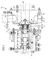
figure 1 is a raised sectional side view of a centrifugal compressor equipped with an abradable and anti-encrustation coating according to the present invention; -
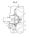
figure 2 is an enlarged sectional view which shows in detail the portion of the compressor offigure 1 on which the abradable and anti-encrustation coating according to the present invention is applied; -
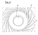
figure 3 is a plan view of the portion of the compressor offigure 1 on which the abradable and anti-encrustation coating according to the present invention is applied; and -
figure 4 is a highly enlarged sectional view of an application example of the abradable and anti-encrustation coating according to the present invention. - With reference to the figures, these show a generic centrifugal compressor, of the single-stage type, indicated as a whole with the
reference number 10. Thecompressor 10 comprises a casing orstator 12 in which ashaft 14 is rotatingly assembled, equipped at one of its ends, with arotor 16, in turn equipped with a series ofcircumferential vanes 18 having a substantially radial development. - A
diffuser 20, which defines anaxial duct 22, generally have a truncated-conical form, is made integral with thecasing 12, in correspondence with therotor 16, for the suction of the gas. On thediffuser 20 there is also asupply chamber 24, having a toroidal form, for the pressurized gas leaving therotor 16, saidsupply chamber 24 sending the compressed gas towards aradial outlet duct 26. - In the embodiment illustrated, the
vanes 18 of therotor 16 have an outer edge with a curved profile which faces a corresponding curved profile obtained on anannular surface portion 28 of thediffuser 20 in contact with therotor 16 itself, as can be observed in detail infigure 2 . - As the distance between the
moveable vanes 18 and the fixedannular surface portion 28 is reduced to the minimum for a better performance of thecompressor 10 and to prevent interference phenomena between therotor 16 and thediffuser 20, saidannular surface portion 28 is at least partially covered with a coating made with a material which can be abraded on the part of the outer edge of thevanes 18, especially in the start-up phase of thecompressor 10 or in the presence of vibrations of a significant entity. - According to the invention, said coating of abradable material consists of a first metal-based
coating layer 30, or lower layer, applied on the surface of theannular portion 28 of thediffuser 20, and a second polymer-basedcoating layer 32, or upper layer, applied on the first metal-basedcoating layer 30. - The thickness of the upper polymer-based
coating layer 32 preferably ranges from 1 mm to 1.5 mm, with a particularly preferred thickness value of about 1.2 mm. The thickness of the first metal-basedcoating layer 30, on the other hand, can vary according to the manufacturing tolerances of thecompressor 10, i.e. on the basis of the distance between thevanes 18 of therotor 16 and theannular portion 28 of thediffuser 20. On the basis of experimental tests carried out on compressors having components with predefined dimensions, it was possible to define an average thickness ranging from 1 mm to about 1.5 mm for said lower coating layer. - Although numerous metal-based and polymer-based materials can be used for the
first coating layer 30 and thesecond coating layer 32, respectively, from experimental tests it has been found that a particularly preferred material for thefirst coating layer 30 can consist of an aluminum powder at 99%, anchored to the metallic substrate by means of a nickel and aluminum (NiAl) alloy. In the specific embodiment example illustrated herein, said material for thefirst coating layer 30 was obtained by combining known coatings with the commercial name "Metco 54NS" and "Metco 450" (anchoring agent) produced by Sulzer Metco. - For the
second coating layer 32, which forms the abradable portion of the coating applied to the surface of theannular portion 28 of thediffuser 20, a material known with the trade-name "Halar® ECTFE 6014", produced by Solvay, was selected in the specific embodiment example illustrated herein. This material is a high-performance thermoplastic fluoropolymer (ethylene-chloro-trifluoroethylene), which can be easily applied as a particularly smooth coating. This coating has excellent insulating properties, resistance to atmospheric agents and radiations. It also has good adhesion to the underlying coating, is easy to clean and has chemical resistance to most acids, bases and industrial solvents. At the same time, it guarantees sufficient abradable characteristics on the part of thevanes 18 of therotor 16. - Operationally, after defining and insulating the
portion 28 of thediffuser 20 on which the abradable coating according to the invention is to be applied, the application is effected, on the basis of known methods, of the first metal-basedcoating layer 30. Once the thickness of thecoating layer 30 applied has been measured, verifying that it corresponds to the thickness envisaged on the basis of the tolerances between therotor 16 anddiffuser 20, the second polymer-basedcoating layer 32 is applied. - A method adopted for the application of the
second coating layer 32, for example, corresponds to the following procedure: - visual control of the
first aluminum coating 30, in order to verify the absence of impact and damage; - thermal degreasing in an oven at a temperature of about 300°C and for about 30 minutes;
- sandblasting, with aluminum oxide at a maximum pressure of 4 bar, of the
aluminum layer 30 previously applied, covering the areas to be protected with a strip of paper and subsequent blowing with compressed air; - application in layers, after interfacing with primers, of the abradable and
anti-encrustation coating layer 32 with a fluid bed electrostatic gun onto the piece preheated in an oven, at a temperature of about 270°C and for about 30 minutes; and - cleaning and final controls of the thickness and porosity with a spessimeter for nonmagnetic bases and scintillograph at 5,000 Volts with direct current, respectively.
- At this point, it is possible to assemble the
diffuser 20 equipped with the abradable coating according to the invention. - The experimental tests effected showed that this coating has a very low surface roughness (< 0.2 µm), measured therefore on the upper polymer-based
coating layer 32. At the same time, thelower layer 30 has significant adhesion values to the substrate of thediffuser 20, resisting stress value of over 40 MPa. - These combined characteristics demonstrate the anti-encrustation properties of the coating according to the invention, which maintains a limited surface roughness also after the envisaged abrasion on the part of the rotor vanes. Furthermore, the resistance to contaminating agents of the upper layer avoids any possibility of even partial detachment of the underlying metallic layer, protecting it, with evident advantages in terms of durability and efficiency of the compressor.
- It can thus be seen that the abradable and anti-encrustation coating for rotating fluid machines, in particular for centrifugal compressors which process gases containing contaminating agents, according to the present invention, achieves the objectives indicated above. The abradable and anti-encrustation coating for centrifugal compressors of the present invention thus conceived can in any case undergo numerous modifications and variants, all included in the same inventive concept. The protection scope of the invention is therefore defined by the enclosed claims.
Claims (5)
- A method for the application of an abradable and anti-encrustation coating on a rotating fluid machine (10) of the type comprising a casing (12), in which a shaft (14) equipped with at least one rotor (16) having a series of circumferential vanes (18) is rotatingly assembled, and at least one diffuser (20) integral with said casing (12), is, the outer edge of each circumferential vane (18) facing an annular surface portion (28) of said diffuser (20), the method comprising the following phases:insulating said annular surface portion (28) of said diffuser (20) on which said abradable and anti-encrustation coating is to be applied;applying a first metal-based coating layer (30) on said portion of said diffuser (20);measuring the thickness of said first metal-based coating layer (30);verifying that said thickness of said first metal-based coating layer (30) corresponds to the thickness envisaged on the basis of the tolerances between said rotor (16) and said diffuser (20);applying a second polymer-based coating layer (32) on said first metal-based coating layer (30).
- The method according to claim 1, characterized in that said second polymer-based coating layer (32) is applied according to the following phases:visual control of said first metal-based coating layer (30) in order to verify the absence of impact and damage;thermal degreasing in an oven at a temperature of about 300°C and for about 30 minutes;sandblasting, with aluminum oxide at a maximum pressure of 4 bar, of said first coating layer (30), covering the areas to be protected with a strip of paper and subsequent blowing with compressed air;application in layers, after interfacing with primers, of said second polymer-based coating layer (32) with a fluid bed electrostatic gun onto the piece preheated in an oven, at a temperature of about 270°C and for about 30 minutes; andcleaning and final controls of the thickness and porosity with a spessimeter for non-magnetic bases and scintillograph at 5,000 Volts with direct current, respectively.
- The method according to claim 1, characterized in that said lower metal-based coating layer (30) consists of a base of aluminum powder at 99% and a nickel and aluminum (NiAl) binder.
- The method according to claim 1, characterized in that said upper polymer-based coating layer (32) is a thermoplastic fluoropolymer.
- The method according to claim 4, characterized in that said thermoplastic fluoropolymer is ethylene-chloro-trifluoroethylene.
Applications Claiming Priority (1)
| Application Number | Priority Date | Filing Date | Title |
|---|---|---|---|
| ITMI20070665 ITMI20070665A1 (en) | 2007-03-30 | 2007-03-30 | ABRADIBLE AND ANTI-ROUND COATING FOR ROTARY MACHINES IN LUIDO |
Publications (3)
| Publication Number | Publication Date |
|---|---|
| EP1992419A2 EP1992419A2 (en) | 2008-11-19 |
| EP1992419A3 EP1992419A3 (en) | 2010-03-03 |
| EP1992419B1 true EP1992419B1 (en) | 2013-05-15 |
Family
ID=39791728
Family Applications (1)
| Application Number | Title | Priority Date | Filing Date |
|---|---|---|---|
| EP20080153019 Not-in-force EP1992419B1 (en) | 2007-03-30 | 2008-03-19 | Abradable and anti-encrustation coating for rotating fluid machines |
Country Status (5)
| Country | Link |
|---|---|
| US (1) | US20080241527A1 (en) |
| EP (1) | EP1992419B1 (en) |
| JP (1) | JP5498663B2 (en) |
| CN (1) | CN101275583B (en) |
| IT (1) | ITMI20070665A1 (en) |
Families Citing this family (5)
| Publication number | Priority date | Publication date | Assignee | Title |
|---|---|---|---|---|
| FR2947016B1 (en) * | 2009-06-17 | 2013-07-12 | Snecma | CENTRIFUGAL COMPRESSOR. |
| GB0912796D0 (en) * | 2009-07-23 | 2009-08-26 | Cummins Turbo Tech Ltd | Compressor,turbine and turbocharger |
| WO2017076792A1 (en) * | 2015-11-03 | 2017-05-11 | Nuovo Pignone Tecnologie Srl | Diffuser of rotating fluid machines |
| US10634042B2 (en) * | 2016-03-18 | 2020-04-28 | Mitsubishi Heavy Industries Engine & Turbocharger, Ltd. | Rotating machine and method for manufacturing casing for rotating machine |
| US11603588B1 (en) * | 2021-08-30 | 2023-03-14 | General Electric Company | Oxidation and wear resistant coating |
Family Cites Families (30)
| Publication number | Priority date | Publication date | Assignee | Title |
|---|---|---|---|---|
| US3758124A (en) * | 1971-05-17 | 1973-09-11 | Koppers Co Inc | Nickel-aluminum-titanium oxide flame-spray coating for bearing and piston ring member wear surfaces |
| US3843278A (en) * | 1973-06-04 | 1974-10-22 | United Aircraft Corp | Abradable seal construction |
| JPS5242906U (en) * | 1975-09-22 | 1977-03-26 | ||
| US4724172A (en) * | 1983-12-29 | 1988-02-09 | Sermatech International, Inc. | Thick coating compositions |
| JPS6285198A (en) * | 1985-10-11 | 1987-04-18 | Mitsubishi Heavy Ind Ltd | Compressor |
| US4818734A (en) * | 1986-09-17 | 1989-04-04 | Lanxide Technology Company, Lp | Method for in situ tailoring the metallic component of ceramic articles |
| JPS6352992U (en) * | 1986-09-25 | 1988-04-09 | ||
| JPS6460701A (en) * | 1987-08-31 | 1989-03-07 | Toyota Motor Corp | Flame coating film for controlling clearance gap |
| JPS6473197A (en) * | 1987-09-14 | 1989-03-17 | Toyota Motor Corp | Automobile turbo compressor housing |
| EP0360622B1 (en) * | 1988-09-22 | 1999-07-28 | Sumitomo Chemical Company Limited | Novel optically active benzene derivatives, process for producing the same and liquid-crystalline composition containing said derivatives as liquid-crystalline compound and light switching elements |
| JPH0368529U (en) * | 1989-11-06 | 1991-07-05 | ||
| JPH03237299A (en) * | 1990-02-09 | 1991-10-23 | Toyota Motor Corp | Manufacture of clearance adjusting film layer |
| CN2091370U (en) * | 1991-05-14 | 1991-12-25 | 王睢秦 | Fluoroplastic lining no-discharge pump |
| US5262241A (en) * | 1991-08-26 | 1993-11-16 | Eeonyx Corporation | Surface coated products |
| EP0739953B1 (en) * | 1995-04-25 | 2002-11-27 | Sermatech International Inc. | Anti-fouling coating for turbomachinery |
| JPH10220395A (en) * | 1997-02-06 | 1998-08-18 | Tochigi Fuji Ind Co Ltd | Centrifugal fluid machine |
| JPH1130190A (en) * | 1997-07-09 | 1999-02-02 | Tochigi Fuji Ind Co Ltd | Centrifugal fluid machine |
| US6234749B1 (en) * | 1998-08-21 | 2001-05-22 | Ishikawajima-Harima Heavy Industries Co., Ltd. | Centrifugal compressor |
| US6012900A (en) * | 1998-09-23 | 2000-01-11 | Kennedy; Steven C. | Submergible pumping system with thermal sprayed polymeric wear surfaces |
| DE10014486C2 (en) * | 2000-03-23 | 2003-06-12 | Dieter Kampmeier | Process for applying a non-stick layer |
| JP4554762B2 (en) * | 2000-05-16 | 2010-09-29 | 日新製鋼株式会社 | Radiant tube excellent in high-temperature oxidation resistance and manufacturing method |
| CN2448962Y (en) * | 2000-10-18 | 2001-09-19 | 李志刚 | Compound material made wearing-resistant blower fan for ash exhausting |
| US6365222B1 (en) * | 2000-10-27 | 2002-04-02 | Siemens Westinghouse Power Corporation | Abradable coating applied with cold spray technique |
| ITMI20011682A1 (en) * | 2001-08-02 | 2003-02-02 | Ausimont Spa | METAL SUBSTRATES COATED WITH FLUOROPOLYMERS |
| US6830641B2 (en) * | 2001-08-13 | 2004-12-14 | Saint-Gobain Performance Plastics Corporation | Method of making a seal formed from polymer laminated metallic constructions |
| DE202004010821U1 (en) * | 2003-07-23 | 2004-12-23 | The Boc Group Plc, Windlesham | vacuum component |
| CN1255635C (en) * | 2003-09-23 | 2006-05-10 | 上海应用技术学院 | Method of preventing local wear and erosion of impeller machine |
| JP2006063895A (en) * | 2004-08-27 | 2006-03-09 | Mitsubishi Heavy Ind Ltd | Centrifugal compressor |
| CN2802133Y (en) * | 2005-07-05 | 2006-08-02 | 宜兴市宙斯泵业有限公司 | Corrision-resisting, wear-resisting front cover of centrifugal pump |
| GB0613715D0 (en) | 2006-07-11 | 2006-08-23 | Rolls Royce Plc | A seal between relatively moveable members |
-
2007
- 2007-03-30 IT ITMI20070665 patent/ITMI20070665A1/en unknown
-
2008
- 2008-03-17 US US12/049,593 patent/US20080241527A1/en not_active Abandoned
- 2008-03-19 EP EP20080153019 patent/EP1992419B1/en not_active Not-in-force
- 2008-03-28 CN CN2008100874768A patent/CN101275583B/en not_active Expired - Fee Related
- 2008-03-28 JP JP2008085236A patent/JP5498663B2/en not_active Expired - Fee Related
Also Published As
| Publication number | Publication date |
|---|---|
| CN101275583A (en) | 2008-10-01 |
| ITMI20070665A1 (en) | 2008-09-30 |
| EP1992419A2 (en) | 2008-11-19 |
| US20080241527A1 (en) | 2008-10-02 |
| CN101275583B (en) | 2013-05-29 |
| JP5498663B2 (en) | 2014-05-21 |
| JP2008255486A (en) | 2008-10-23 |
| EP1992419A3 (en) | 2010-03-03 |
Similar Documents
| Publication | Publication Date | Title |
|---|---|---|
| CN102753833B (en) | With machine and the method that can grind ridge | |
| EP2050931B1 (en) | Systems and methods involving abradable air seals | |
| CA2252658C (en) | Columnar zirconium oxide abrasive coating for a gas turbine engine seal system | |
| JP4051672B2 (en) | Rotary blower | |
| JP6612096B2 (en) | Abradable seal and method of forming abradable seal | |
| US20180347390A1 (en) | Turbine Clearance Control Coatings and Method | |
| EP1992419A2 (en) | Abradable and anti-encrustation coating for rotating fluid machines | |
| JP2016098810A (en) | Abradable composition and seal of axial flow turbo machine compressor casing | |
| EP1801472B1 (en) | Sealing device | |
| JP2017061934A (en) | Airfoil structure with ptal bond coating and thermal barrier coating, and corresponding manufacturing method | |
| JPH0999273A (en) | Nonpolluting coating film of turbo type engine | |
| EP3456928B1 (en) | Blade outer air seal for gas turbine engines in high erosion environment | |
| EP3143259A1 (en) | Method of manufacturing a component of a turbomachine, component of a turbomachine and turbomachine | |
| EP0799999B1 (en) | A rotor for turbomolecular pump | |
| US7410701B2 (en) | Component for rotary machine and rotary machine | |
| US20160186768A1 (en) | Diffuser of rotating fluid machines | |
| US8992169B2 (en) | Layer system for rotor/stator seal of a turbomachine and method for producing this type of layer system | |
| WO2017076792A1 (en) | Diffuser of rotating fluid machines | |
| CN116507790A (en) | High lubricity abradable material and abradable coating, and turbomachinery including seals formed from said coating | |
| JP2018535322A (en) | Turbine clearance control coating and method | |
| JP2011074797A (en) | Blade, manufacturing method therefor, and rotary machine |
Legal Events
| Date | Code | Title | Description |
|---|---|---|---|
| PUAI | Public reference made under article 153(3) epc to a published international application that has entered the european phase |
Free format text: ORIGINAL CODE: 0009012 |
|
| AK | Designated contracting states |
Kind code of ref document: A2 Designated state(s): AT BE BG CH CY CZ DE DK EE ES FI FR GB GR HR HU IE IS IT LI LT LU LV MC MT NL NO PL PT RO SE SI SK TR |
|
| AX | Request for extension of the european patent |
Extension state: AL BA MK RS |
|
| PUAL | Search report despatched |
Free format text: ORIGINAL CODE: 0009013 |
|
| AK | Designated contracting states |
Kind code of ref document: A3 Designated state(s): AT BE BG CH CY CZ DE DK EE ES FI FR GB GR HR HU IE IS IT LI LT LU LV MC MT NL NO PL PT RO SE SI SK TR |
|
| AX | Request for extension of the european patent |
Extension state: AL BA MK RS |
|
| 17P | Request for examination filed |
Effective date: 20100903 |
|
| AKX | Designation fees paid |
Designated state(s): AT BE BG CH CY CZ DE DK EE ES FI FR GB GR HR HU IE IS IT LI LT LU LV MC MT NL NO PL PT RO SE SI SK TR |
|
| 17Q | First examination report despatched |
Effective date: 20101228 |
|
| REG | Reference to a national code |
Ref country code: DE Ref legal event code: R079 Ref document number: 602008024536 Country of ref document: DE Free format text: PREVIOUS MAIN CLASS: B05D0005080000 Ipc: F04D0029020000 |
|
| RIC1 | Information provided on ipc code assigned before grant |
Ipc: F04D 29/44 20060101ALI20120223BHEP Ipc: F04D 29/02 20060101AFI20120223BHEP Ipc: F04D 29/28 20060101ALI20120223BHEP Ipc: B05D 5/08 20060101ALI20120223BHEP |
|
| GRAP | Despatch of communication of intention to grant a patent |
Free format text: ORIGINAL CODE: EPIDOSNIGR1 |
|
| GRAS | Grant fee paid |
Free format text: ORIGINAL CODE: EPIDOSNIGR3 |
|
| GRAA | (expected) grant |
Free format text: ORIGINAL CODE: 0009210 |
|
| AK | Designated contracting states |
Kind code of ref document: B1 Designated state(s): AT BE BG CH CY CZ DE DK EE ES FI FR GB GR HR HU IE IS IT LI LT LU LV MC MT NL NO PL PT RO SE SI SK TR |
|
| REG | Reference to a national code |
Ref country code: CH Ref legal event code: EP Ref country code: GB Ref legal event code: FG4D |
|
| REG | Reference to a national code |
Ref country code: AT Ref legal event code: REF Ref document number: 612301 Country of ref document: AT Kind code of ref document: T Effective date: 20130615 |
|
| REG | Reference to a national code |
Ref country code: IE Ref legal event code: FG4D |
|
| REG | Reference to a national code |
Ref country code: CH Ref legal event code: NV Representative=s name: SERVOPATENT GMBH, CH |
|
| REG | Reference to a national code |
Ref country code: DE Ref legal event code: R096 Ref document number: 602008024536 Country of ref document: DE Effective date: 20130711 |
|
| REG | Reference to a national code |
Ref country code: NL Ref legal event code: T3 |
|
| REG | Reference to a national code |
Ref country code: NO Ref legal event code: T2 Effective date: 20130515 |
|
| REG | Reference to a national code |
Ref country code: LT Ref legal event code: MG4D |
|
| PG25 | Lapsed in a contracting state [announced via postgrant information from national office to epo] |
Ref country code: FI Free format text: LAPSE BECAUSE OF FAILURE TO SUBMIT A TRANSLATION OF THE DESCRIPTION OR TO PAY THE FEE WITHIN THE PRESCRIBED TIME-LIMIT Effective date: 20130515 Ref country code: ES Free format text: LAPSE BECAUSE OF FAILURE TO SUBMIT A TRANSLATION OF THE DESCRIPTION OR TO PAY THE FEE WITHIN THE PRESCRIBED TIME-LIMIT Effective date: 20130826 Ref country code: SI Free format text: LAPSE BECAUSE OF FAILURE TO SUBMIT A TRANSLATION OF THE DESCRIPTION OR TO PAY THE FEE WITHIN THE PRESCRIBED TIME-LIMIT Effective date: 20130515 Ref country code: IS Free format text: LAPSE BECAUSE OF FAILURE TO SUBMIT A TRANSLATION OF THE DESCRIPTION OR TO PAY THE FEE WITHIN THE PRESCRIBED TIME-LIMIT Effective date: 20130915 Ref country code: SE Free format text: LAPSE BECAUSE OF FAILURE TO SUBMIT A TRANSLATION OF THE DESCRIPTION OR TO PAY THE FEE WITHIN THE PRESCRIBED TIME-LIMIT Effective date: 20130515 Ref country code: LT Free format text: LAPSE BECAUSE OF FAILURE TO SUBMIT A TRANSLATION OF THE DESCRIPTION OR TO PAY THE FEE WITHIN THE PRESCRIBED TIME-LIMIT Effective date: 20130515 Ref country code: GR Free format text: LAPSE BECAUSE OF FAILURE TO SUBMIT A TRANSLATION OF THE DESCRIPTION OR TO PAY THE FEE WITHIN THE PRESCRIBED TIME-LIMIT Effective date: 20130816 Ref country code: PT Free format text: LAPSE BECAUSE OF FAILURE TO SUBMIT A TRANSLATION OF THE DESCRIPTION OR TO PAY THE FEE WITHIN THE PRESCRIBED TIME-LIMIT Effective date: 20130916 |
|
| PG25 | Lapsed in a contracting state [announced via postgrant information from national office to epo] |
Ref country code: BG Free format text: LAPSE BECAUSE OF FAILURE TO SUBMIT A TRANSLATION OF THE DESCRIPTION OR TO PAY THE FEE WITHIN THE PRESCRIBED TIME-LIMIT Effective date: 20130815 Ref country code: HR Free format text: LAPSE BECAUSE OF FAILURE TO SUBMIT A TRANSLATION OF THE DESCRIPTION OR TO PAY THE FEE WITHIN THE PRESCRIBED TIME-LIMIT Effective date: 20130515 Ref country code: PL Free format text: LAPSE BECAUSE OF FAILURE TO SUBMIT A TRANSLATION OF THE DESCRIPTION OR TO PAY THE FEE WITHIN THE PRESCRIBED TIME-LIMIT Effective date: 20130515 |
|
| PG25 | Lapsed in a contracting state [announced via postgrant information from national office to epo] |
Ref country code: LV Free format text: LAPSE BECAUSE OF FAILURE TO SUBMIT A TRANSLATION OF THE DESCRIPTION OR TO PAY THE FEE WITHIN THE PRESCRIBED TIME-LIMIT Effective date: 20130515 |
|
| PG25 | Lapsed in a contracting state [announced via postgrant information from national office to epo] |
Ref country code: DK Free format text: LAPSE BECAUSE OF FAILURE TO SUBMIT A TRANSLATION OF THE DESCRIPTION OR TO PAY THE FEE WITHIN THE PRESCRIBED TIME-LIMIT Effective date: 20130515 Ref country code: EE Free format text: LAPSE BECAUSE OF FAILURE TO SUBMIT A TRANSLATION OF THE DESCRIPTION OR TO PAY THE FEE WITHIN THE PRESCRIBED TIME-LIMIT Effective date: 20130515 Ref country code: SK Free format text: LAPSE BECAUSE OF FAILURE TO SUBMIT A TRANSLATION OF THE DESCRIPTION OR TO PAY THE FEE WITHIN THE PRESCRIBED TIME-LIMIT Effective date: 20130515 |
|
| PG25 | Lapsed in a contracting state [announced via postgrant information from national office to epo] |
Ref country code: RO Free format text: LAPSE BECAUSE OF FAILURE TO SUBMIT A TRANSLATION OF THE DESCRIPTION OR TO PAY THE FEE WITHIN THE PRESCRIBED TIME-LIMIT Effective date: 20130515 |
|
| PLBE | No opposition filed within time limit |
Free format text: ORIGINAL CODE: 0009261 |
|
| STAA | Information on the status of an ep patent application or granted ep patent |
Free format text: STATUS: NO OPPOSITION FILED WITHIN TIME LIMIT |
|
| 26N | No opposition filed |
Effective date: 20140218 |
|
| REG | Reference to a national code |
Ref country code: DE Ref legal event code: R097 Ref document number: 602008024536 Country of ref document: DE Effective date: 20140218 |
|
| PG25 | Lapsed in a contracting state [announced via postgrant information from national office to epo] |
Ref country code: LU Free format text: LAPSE BECAUSE OF FAILURE TO SUBMIT A TRANSLATION OF THE DESCRIPTION OR TO PAY THE FEE WITHIN THE PRESCRIBED TIME-LIMIT Effective date: 20140319 |
|
| GBPC | Gb: european patent ceased through non-payment of renewal fee |
Effective date: 20140319 |
|
| REG | Reference to a national code |
Ref country code: IE Ref legal event code: MM4A |
|
| PG25 | Lapsed in a contracting state [announced via postgrant information from national office to epo] |
Ref country code: IE Free format text: LAPSE BECAUSE OF NON-PAYMENT OF DUE FEES Effective date: 20140319 Ref country code: GB Free format text: LAPSE BECAUSE OF NON-PAYMENT OF DUE FEES Effective date: 20140319 |
|
| PGFP | Annual fee paid to national office [announced via postgrant information from national office to epo] |
Ref country code: CZ Payment date: 20150311 Year of fee payment: 8 |
|
| PGFP | Annual fee paid to national office [announced via postgrant information from national office to epo] |
Ref country code: AT Payment date: 20150304 Year of fee payment: 8 |
|
| PG25 | Lapsed in a contracting state [announced via postgrant information from national office to epo] |
Ref country code: MT Free format text: LAPSE BECAUSE OF FAILURE TO SUBMIT A TRANSLATION OF THE DESCRIPTION OR TO PAY THE FEE WITHIN THE PRESCRIBED TIME-LIMIT Effective date: 20130515 |
|
| REG | Reference to a national code |
Ref country code: FR Ref legal event code: PLFP Year of fee payment: 9 |
|
| PGFP | Annual fee paid to national office [announced via postgrant information from national office to epo] |
Ref country code: CH Payment date: 20160328 Year of fee payment: 9 Ref country code: NL Payment date: 20160326 Year of fee payment: 9 |
|
| PG25 | Lapsed in a contracting state [announced via postgrant information from national office to epo] |
Ref country code: MC Free format text: LAPSE BECAUSE OF FAILURE TO SUBMIT A TRANSLATION OF THE DESCRIPTION OR TO PAY THE FEE WITHIN THE PRESCRIBED TIME-LIMIT Effective date: 20130515 |
|
| PGFP | Annual fee paid to national office [announced via postgrant information from national office to epo] |
Ref country code: BE Payment date: 20160328 Year of fee payment: 9 Ref country code: FR Payment date: 20160328 Year of fee payment: 9 |
|
| PG25 | Lapsed in a contracting state [announced via postgrant information from national office to epo] |
Ref country code: CY Free format text: LAPSE BECAUSE OF FAILURE TO SUBMIT A TRANSLATION OF THE DESCRIPTION OR TO PAY THE FEE WITHIN THE PRESCRIBED TIME-LIMIT Effective date: 20130515 |
|
| PG25 | Lapsed in a contracting state [announced via postgrant information from national office to epo] |
Ref country code: TR Free format text: LAPSE BECAUSE OF FAILURE TO SUBMIT A TRANSLATION OF THE DESCRIPTION OR TO PAY THE FEE WITHIN THE PRESCRIBED TIME-LIMIT Effective date: 20130515 Ref country code: HU Free format text: LAPSE BECAUSE OF FAILURE TO SUBMIT A TRANSLATION OF THE DESCRIPTION OR TO PAY THE FEE WITHIN THE PRESCRIBED TIME-LIMIT; INVALID AB INITIO Effective date: 20080319 |
|
| PGFP | Annual fee paid to national office [announced via postgrant information from national office to epo] |
Ref country code: DE Payment date: 20160331 Year of fee payment: 9 Ref country code: NO Payment date: 20160331 Year of fee payment: 9 |
|
| PGFP | Annual fee paid to national office [announced via postgrant information from national office to epo] |
Ref country code: IT Payment date: 20160323 Year of fee payment: 9 |
|
| REG | Reference to a national code |
Ref country code: AT Ref legal event code: MM01 Ref document number: 612301 Country of ref document: AT Kind code of ref document: T Effective date: 20160319 |
|
| PG25 | Lapsed in a contracting state [announced via postgrant information from national office to epo] |
Ref country code: CZ Free format text: LAPSE BECAUSE OF NON-PAYMENT OF DUE FEES Effective date: 20160319 |
|
| PG25 | Lapsed in a contracting state [announced via postgrant information from national office to epo] |
Ref country code: AT Free format text: LAPSE BECAUSE OF NON-PAYMENT OF DUE FEES Effective date: 20160319 |
|
| REG | Reference to a national code |
Ref country code: DE Ref legal event code: R119 Ref document number: 602008024536 Country of ref document: DE |
|
| REG | Reference to a national code |
Ref country code: NO Ref legal event code: MMEP |
|
| REG | Reference to a national code |
Ref country code: CH Ref legal event code: PL |
|
| REG | Reference to a national code |
Ref country code: NL Ref legal event code: MM Effective date: 20170401 |
|
| REG | Reference to a national code |
Ref country code: FR Ref legal event code: ST Effective date: 20171130 |
|
| PG25 | Lapsed in a contracting state [announced via postgrant information from national office to epo] |
Ref country code: FR Free format text: LAPSE BECAUSE OF NON-PAYMENT OF DUE FEES Effective date: 20170331 Ref country code: NL Free format text: LAPSE BECAUSE OF NON-PAYMENT OF DUE FEES Effective date: 20170401 Ref country code: DE Free format text: LAPSE BECAUSE OF NON-PAYMENT OF DUE FEES Effective date: 20171003 Ref country code: NO Free format text: LAPSE BECAUSE OF NON-PAYMENT OF DUE FEES Effective date: 20170331 |
|
| PG25 | Lapsed in a contracting state [announced via postgrant information from national office to epo] |
Ref country code: LI Free format text: LAPSE BECAUSE OF NON-PAYMENT OF DUE FEES Effective date: 20170331 Ref country code: CH Free format text: LAPSE BECAUSE OF NON-PAYMENT OF DUE FEES Effective date: 20170331 Ref country code: IT Free format text: LAPSE BECAUSE OF NON-PAYMENT OF DUE FEES Effective date: 20170319 |
|
| REG | Reference to a national code |
Ref country code: BE Ref legal event code: MM Effective date: 20170331 |
|
| PG25 | Lapsed in a contracting state [announced via postgrant information from national office to epo] |
Ref country code: BE Free format text: LAPSE BECAUSE OF NON-PAYMENT OF DUE FEES Effective date: 20170331 |