EP1992391A1 - Collapsible throwing toy having timed release mechanism - Google Patents
Collapsible throwing toy having timed release mechanism Download PDFInfo
- Publication number
- EP1992391A1 EP1992391A1 EP08154301A EP08154301A EP1992391A1 EP 1992391 A1 EP1992391 A1 EP 1992391A1 EP 08154301 A EP08154301 A EP 08154301A EP 08154301 A EP08154301 A EP 08154301A EP 1992391 A1 EP1992391 A1 EP 1992391A1
- Authority
- EP
- European Patent Office
- Prior art keywords
- suction cup
- flat surface
- arcuate sections
- assembly according
- shape
- Prior art date
- Legal status (The legal status is an assumption and is not a legal conclusion. Google has not performed a legal analysis and makes no representation as to the accuracy of the status listed.)
- Withdrawn
Links
- 230000007246 mechanism Effects 0.000 title description 3
- 238000013022 venting Methods 0.000 claims abstract description 3
- 230000000087 stabilizing effect Effects 0.000 claims description 10
- 238000000034 method Methods 0.000 claims description 8
- 208000031872 Body Remains Diseases 0.000 abstract description 2
- 230000000712 assembly Effects 0.000 description 12
- 238000000429 assembly Methods 0.000 description 12
- 230000006835 compression Effects 0.000 description 4
- 238000007906 compression Methods 0.000 description 4
- 230000005484 gravity Effects 0.000 description 3
- 244000260524 Chrysanthemum balsamita Species 0.000 description 2
- 235000005633 Chrysanthemum balsamita Nutrition 0.000 description 2
- 238000004519 manufacturing process Methods 0.000 description 2
- 238000009987 spinning Methods 0.000 description 2
- 235000002595 Solanum tuberosum Nutrition 0.000 description 1
- 244000061456 Solanum tuberosum Species 0.000 description 1
- 230000009471 action Effects 0.000 description 1
- 230000004913 activation Effects 0.000 description 1
- 230000002411 adverse Effects 0.000 description 1
- 230000008859 change Effects 0.000 description 1
- 230000003278 mimic effect Effects 0.000 description 1
- 238000012986 modification Methods 0.000 description 1
- 230000004048 modification Effects 0.000 description 1
- 238000003825 pressing Methods 0.000 description 1
Images



Classifications
-
- A—HUMAN NECESSITIES
- A63—SPORTS; GAMES; AMUSEMENTS
- A63H—TOYS, e.g. TOPS, DOLLS, HOOPS OR BUILDING BLOCKS
- A63H33/00—Other toys
- A63H33/18—Throwing or slinging toys, e.g. flying disc toys
Definitions
- the present invention relates to toy objects that are spring biased in an expanded configuration, yet can be temporarily configured into a collapsed configuration. More particularly, the present Invention relates to thrown toy objects, such as balls, that can be temporarily pressed into a collapsed configuration, wherein the thrown toy pops back into an expanded configuration a short time later. The present invention also relates to the method of manufacturing such toy ,objects.
- the collapsible throwing toy can be configured as either a ball or as a disc, depending upon whether or not the toy is compressed.
- collapsible throwing toys typically have some sort of biasing element that biases the collapsible throwing toy into its expanded, ball-like configuration.
- a collapsible throwing toy is shown that has an internal coil spring.
- the coil spring biases apart the upper and lower hemispheres of the toy.
- the collapsible throwing toy can be temporarily configured like a disc by compressing the internal coil spring and resisting the bias of the coil spring with a momentary suction cup connection between the upper and lower hemispheres. As soon as the momentary suction cup connection fails, the internal coil spring pops the collapsible throwing toy back into its expanded ball-like configuration.
- Reliance upon a suction cup to trigger the expansion of a collapsed toy has certain inherent problems. Depending upon the game being played with a collapsed toy, the desired period before it pops back into its expanding shape may vary. If a group of people are playing "hot potato" with the toy, a delay of a few minutes may be desirable. If the collapsed toy is being used to play catch, it is usually desirable for a collapsed ball toy to expand back into its ball shape after being thrown and before it is caught. This is a window of only a few seconds. Using a standard suction cup triggering mechanism, it is very difficult to get the toy to activate within the desired time window. If a suction cup is wet or is heavily compressed, it may not release until several seconds, or even minutes, have elapsed. If a suction cup is dirty, bent or under compressed, it may release in only one or two seconds.
- the present invention is a toy assembly and its method of operation.
- the toy assembly is an oblong ball, spherical ball or similar object that can be temporarily compressed into a disc-shaped object. A short time after compression, the toy pops back into its original ball-like shape.
- the toy assembly has a body that can be selectively configured between an expanded shape and a compressed shape.
- the body is comprised of a plurality of arcuate sections that are symmetrically disposed around a center axis. At least one biasing element is provided for biasing the arcuate sections into their expanded shape.
- a suction cup is disposed in the body at a first end of the body. Additionally, a flat surface is disposed in the body at a second end, opposite the first end. The suction cup engages the flat surface only when the body is collapsed into its compressed shape.
- a vent valve assembly is provided through the flat surface for venting air in between the flat surface and the suction cup.
- the vent valve assembly is manually adjustable. Consequently, a user can control the flow of air between the suction cup and the flat surface.
- the suction cup releases the flat surface when enough air flows into the suction cup to equalize pressure. It will therefore be understood that by controlling the rate that air flows in between the suction cup and the flat surface, a person can selectively control the length of time that the suction cup sticks to the flat surface.
- the vent valve assembly therefore, enables a user to adjust how long the body remains in its compressed shape before it pops back into its expanded shape.
- collapsible throwing toy can be made round, it also can be made oblong to mimic the shape of a football.
- the collapsible throwing toy is configured into the shape of a football.
- Such a shape is exemplary and it will be understood that "balls" of geometric shapes other than spherical are intended to be included within the scope of the invention.
- the collapsible throwing toy 10 has an oblong body 12 that is made from a variety of arcuate sections 14.
- the different arcuate sections 14 that comprise the spherical body 12 are symmetrically disposed around a central axis 20.
- Two end hub assemblies 21, 22 are provided.
- the end hub assemblies 21, 22 are disposed at opposite ends of the oblong body 12. Both end hub assemblies 21, 22 are positioned along the central axis 20 of the collapsible throwing toy 10.
- the plurality of collapsible arcuate sections 14 extend between the two end hub assemblies 21, 22. In the shown embodiment, six collapsible arcuate sections 14 are shown. However, such a configuration is merely exemplary and it should be understood that any plurality of collapsible arcuate sections 14 can be used.
- Each of the collapsible arcuate sections 14 contains an upper panel 16, a lower panel 18 and a joint element 26. If the end hub assemblies 21, 22 are considered to be positioned along the same central axis 20 at different pole ends of the oblong body 12, an imaginary mid-plane 24 exists between the end hub assemblies 21, 22.
- the mid-plane 24 bisects the oblong body 12, dividing the oblong body 12 into an upper half 28 and a lower half 29.
- the joint elements 26 of each of the collapsible arcuate sections 14 are disposed along the mid-plane 24.
- the upper panel 16 of each collapsible arcuate section 14 extends in the upper half 28 of the oblong body 12, above the mid-plane 24.
- the lower panel 18 of each collapsible arcuate section 14 extends in the lower half 29 of the oblong body 12, below the mid-plane 24.
- a suction cup is disposed inside the spherical body 12 of the collapsible throwing toy 10 behind the upper end hub assembly 21.
- a surface that can be temporarily engaged by the suction cup is disposed inside the spherical body 12 of the collapsible throwing toy 10 behind the opposite lower end hub assembly 22.
- the arcuate sections 14 that form the oblong body 12 of the collapsible throwing toy 10 are made to fold at the joint elements 26 along the mid-plane plane 24. However, as will be further explained, the various arcuate sections 14 are engaged by an elastic band that causes the arcuate sections 14 not to bend unless forced to do so. This maintains the collapsible throwing toy 10 in its expanded shape, as is illustrated in Fig. 1 .
- Stabilizing fins 27 are present on the exterior of the elongated body 12. The stabilizing fins 27 help the oblong body 12 fly in a straight spiral when the collapsible throwing toy 10 is in flight in its expanded shape.
- the oblong body 12 of the collapsible throwing toy 10 can be altered into a disc shape by pressing the two end hub assemblies 21, 22 toward each other.
- the two end hub assemblies 21, 22 meet at the imaginary mid-plane 24 of the oblong body 12.
- the upper end hub assembly 21 temporarily engages the opposing lower end hub assembly 22,
- the collapsible arcuate sections 14 fold at the joint elements 26.
- the oblong shape of Fig. 1 therefore transforms into the disc shape of Fig. 2 .
- the stabilizing fins 27 When in the disc shape, the stabilizing fins 27 fold down flat against the compressed arcuate sections 14. In this manner, the stabilizing fins 27 do not adversely affect the ability of the collapsible throwing toy 10 to be thrown like a disc while in its collapsed shape.
- collapsible arcuate sections 14 fold, they each resist the folding deformation with a spring bias.
- the combined bias of all the collapsible arcuate sections 14 creates a force that opposes the compression. This bias causes the collapsible arcuate sections 14 to immediately pop back into an expanded shape the instant the compression force is released or the two end hub assemblies 21, 22 release their interconnection.
- an elastic band 42 is joined to all of the arcuate sections 14 inside the oblong body 12.
- the elastic band 42 travels in the same plane as the mid-plane 24 and connects to the inside of each joint element 26. This biases each joint element 26 toward the central axis 20.
- This bias direction causes the oblong body 12 to stand in its expanded shape.
- the elongated body 12 is compressed, the diameter around the mid-plane 24 expands. This causes the elastic band 42, to stretch and store energy. Due to the pull of the elastic band 42, the oblong body 12 would immediately snap back into its expanded shape should the compression forces be removed.
- the bias of the elastic band 42 is resisted by the engagement of the upper end hub assembly 21 and the lower end hub assembly 22 when the oblong body 12 is fully collapsed.
- the upper end hub assembly 21 has an external plate 30 that lay on the exterior apex of the upper half 28 of the oblong body 12.
- the upper end hub assembly 21 also has an internal plate 32 that lay on the interior.
- a weight compartment is provided that holds a weight 36.
- the weight 36 is used to improve the flight characteristics of the collapsible throwing toy 10, as will later be explained.
- a suction cup 40 extends below the weight 36.
- the suction cup 40 faces inwardly toward the mid-plane 24. Furthermore, the suction cup 40 is aligned with the central axis 20 of the collapsible throwing toy 10.
- An end cap 38 attaches to the external plate 30 of the upper end hub assembly 21.
- the end cap 38 has a curved exterior that complements the curvature of the exterior of the oblong body 12.
- the lower end hub assembly 22 includes a flat attachment plate 44.
- the attachment plate 44 has a flat surface 45 that the suction cup 40 attaches to when the collapsible throwing toy 10 is collapsed.
- a vent hole 46 is disposed through the attachment plate 44. The vent hole 46 enables air to flow in between the suction cup 40 and the attachment plate 44 when the suction cup 40 is connected to the flat surface 45 of the attachment plate 44. If the vent hole 46 were left open, no suction could develop between the suction cup 40 and the attachment plate 44. The suction cup 40 would, therefore, only remain attached to the attachment plate 44 for a moment.
- a vent valve assembly 50 is provided in order to control the flow of air through the vent hole 46.
- the vent valve assembly 50 includes a valve needle 52 that extends into the vent hole 46.
- the valve needle 52 has the ability to completely seal the vent hole 46 or selectively allow controlled volumes of air to flow through the vent hole 46.
- the degree by which the valve needle 52 blocks the vent hole 46 depends upon the distance that the valve needle 52 is inserted into the valve hole 46.
- the valve needle 52 is connected to a threaded rod 54.
- the threaded rod 54 is connected to a manual control knob 56.
- the threaded rod 54 engages the attachment plate 44. Accordingly, it will be understood that as the manual control knob 56 is turned, the threaded rod 54 will move up or down in relation to the attachment plate 44. The depth at which the valve needle 52 is positioned in the vent hole 46 can therefore be selectively controlled by turning the manual control knob 56.
- the suction cup 40 of the upper end hub assembly 21 will only remain attached to the attachment plate 44 of the lower end hub assembly 22 for as long as the air pressure inside the suction cup 40 is lower than ambient pressure. Since the valve assembly 50 enables the amount of air that flows through the vent hole 46 to be controlled, the amount of time that the suction cup 40 engages the attachment plate 44 can be selectively controlled. If the valve assembly 50 is used to close the vent hole 46, the suction cup 40 may remain engaged with the attachment plate 44 for a few minutes. However, if the valve assembly 50 is opened, air is permitted to flow between the suction cup 40 and the attachment plate 44. This quickly eliminates any pressure differential that may exist inside the suction cup 40 and the suction cup 40 may only adhere to the attachment plate 44 for a second or two.
- Attachment time between the suction cup 40 and the attachment plate 44 can therefore be altered as desired from as short as a few seconds to as long as a few minutes.
- the force of the elastic band 42 causes the upper end hub assembly 21 and the lower end hub assembly 22 to separate as the oblong body 12 returns to its expanded shape.
- valve assembly 50 can therefore adjust the valve assembly 50 to either allow for the quick seepage of air or the slow seepage of air. This directly translates into the time that the suction cup 40 remains engaged with the attachment plate 44. A person can therefore adjust the collapsible throwing toy 10 so that it remains collapsed for anywhere from a few seconds to a few minutes.
- an oblong shaped ball like a football
- a football is illustrated.
- the method of play for such a toy is that the collapsible throwing toy 10 is collapsed and thrown as a disc.
- the collapsible throwing toy 10 is adjusted so that it pops into its football shape during flight.
- the collapsible throwing toy 10 In order for the collapsible throwing toy 10 to fly in a stable manner when collapsed, it must fly while spinning with its central axis 20 oriented generally in the vertical. However, when the collapsible throwing toy 10 pops back into its expanded shape, it only experiences stable flight if it is spinning with its central axis 20 generally oriented in the horizontal.
- the stabilizing fins 27 on the oblong body 12 extend when the collapsible throwing toy 10 pops into its expanded shape.
- the stabilizing fins 27 catch air and cause the orientation of the collapsible throwing toy 10 to change.
- the stabilizing fins 27 are preferably curved so that they add spin to the collapsible throwing toy 10 as the collapsible throwing toy 10 flies through the air.
- the second feature that helps the collapsible throwing toy 10 reorient in flight is the internal weights 36 in the upper end hub assembly 21.
- the weights 36 are very near the geometric center of the collapsible throwing toy 10.
- the collapsible throwing toy 10 has a center of gravity that is very close to its geometric center. This enables the collapsible throwing toy 10 to remain stable in flight.
- the weights 36 are located at the upper end of the oblong body 12, far away from the geometric center of the collapsible throwing toy 10. This causes the center of gravity to be offset from the path of flight. Wind resistance will therefore act to reorient the collapsible throwing toy 10 so that both the center of gravity and the geometric center of the collapsible throwing toy 10 are both aligned along the path of flight.
Landscapes
- Toys (AREA)
Abstract
The toy assembly has a body (12) that can be selectively configured between an expanded shape and a compressed shape. The body (12) is comprised of a plurality of arcuate sections (14). At least one biasing element (42) is provided for biasing the arcuate sections into their expanded shape. A suction cup (40) is disposed in the body at a first end of the body. A flat surface (44) is disposed in the body at a second opposite end. The suction cup (40) engages the flat surface (44) only when the body is collapsed into its compressed shape. A vent valve assembly (50) is provided for venting air between the flat surface (44) and the suction cup (40). The suction cup (40) releases the flat surface (44) when enough air flows into the suction cup (40) to equalize pressure. Accordingly, a person can selectively control the length of time that the body remains in its compressed shape.
Description
- In general, the present invention relates to toy objects that are spring biased in an expanded configuration, yet can be temporarily configured into a collapsed configuration. More particularly, the present Invention relates to thrown toy objects, such as balls, that can be temporarily pressed into a collapsed configuration, wherein the thrown toy pops back into an expanded configuration a short time later. The present invention also relates to the method of manufacturing such toy ,objects.
- The prior art is replete with various types of toys that are intended to be thrown. Prominent among such toys are balls and discs. It, therefore, is not surprising that toy manufacturers eventually combined the features of a ball and a disc into a single throwing toy. It is for this reason that collapsible throwing toys were first introduced into the toy market. Collapsible throwing toys are balls, or similar spherically shaped objects, that are comprised of an upper hemisphere and a lower hemisphere. The upper hemisphere and the lower hemisphere are joined together with hinged connections along a common equatorial joint. Due to the hinged connections between the upper hemisphere and the lower hemisphere, the upper and lower hemispheres of the ball can be collapsed flat against each other. When the upper and the lower hemispheres of the toy are collapsed against each other, the toy has the general configuration of a disc. Accordingly, the collapsible throwing toy can be configured as either a ball or as a disc, depending upon whether or not the toy is compressed.
- As the upper and lower hemispheres of the toy are collapsed into a flat configuration, the diameters of the hemispheres expand. To accommodate this expansion, the upper and lower hemispheres of the toy are slotted. When the toy is fully expanded into its ball shape, the slots are closed and the toy has a continuous external surface. Conversely, when the toy is flattened into a disc, the slots open and expand, giving the disc a daisy configuration. A typical daisy configuration of a collapsible throwing toy can be seen by referencing U.S. Patent No. Des 434,457 to Goldman, entitled Collapsible Toy.
- In the prior art, collapsible throwing toys typically have some sort of biasing element that biases the collapsible throwing toy into its expanded, ball-like configuration. For example, in
U.S. Patent No. 5,797,815 to Goldman , entitled Pop-Open Throwing Toy With Controllable Opening Delay And Method Of Operating Same, a collapsible throwing toy is shown that has an internal coil spring. The coil spring biases apart the upper and lower hemispheres of the toy. The collapsible throwing toy can be temporarily configured like a disc by compressing the internal coil spring and resisting the bias of the coil spring with a momentary suction cup connection between the upper and lower hemispheres. As soon as the momentary suction cup connection fails, the internal coil spring pops the collapsible throwing toy back into its expanded ball-like configuration. - Reliance upon a suction cup to trigger the expansion of a collapsed toy has certain inherent problems. Depending upon the game being played with a collapsed toy, the desired period before it pops back into its expanding shape may vary. If a group of people are playing "hot potato" with the toy, a delay of a few minutes may be desirable. If the collapsed toy is being used to play catch, it is usually desirable for a collapsed ball toy to expand back into its ball shape after being thrown and before it is caught. This is a window of only a few seconds. Using a standard suction cup triggering mechanism, it is very difficult to get the toy to activate within the desired time window. If a suction cup is wet or is heavily compressed, it may not release until several seconds, or even minutes, have elapsed. If a suction cup is dirty, bent or under compressed, it may release in only one or two seconds.
- A need therefore exists for a means to actively control the release mechanism of a collapsed ball so that the time period for activation can be selected in a reliable and accurate manner. This need is met by the present invention as described and claimed below.
- The present invention is a toy assembly and its method of operation. The toy assembly is an oblong ball, spherical ball or similar object that can be temporarily compressed into a disc-shaped object. A short time after compression, the toy pops back into its original ball-like shape.
- The toy assembly has a body that can be selectively configured between an expanded shape and a compressed shape. The body is comprised of a plurality of arcuate sections that are symmetrically disposed around a center axis. At least one biasing element is provided for biasing the arcuate sections into their expanded shape. A suction cup is disposed in the body at a first end of the body. Additionally, a flat surface is disposed in the body at a second end, opposite the first end. The suction cup engages the flat surface only when the body is collapsed into its compressed shape.
- A vent valve assembly is provided through the flat surface for venting air in between the flat surface and the suction cup. The vent valve assembly is manually adjustable. Consequently, a user can control the flow of air between the suction cup and the flat surface. The suction cup releases the flat surface when enough air flows into the suction cup to equalize pressure. It will therefore be understood that by controlling the rate that air flows in between the suction cup and the flat surface, a person can selectively control the length of time that the suction cup sticks to the flat surface. The vent valve assembly, therefore, enables a user to adjust how long the body remains in its compressed shape before it pops back into its expanded shape.
- For a better understanding of the present invention, reference is made to the following description of an exemplary embodiment thereof, considered in conjunction with the accompanying drawings, in which:
-
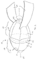
Fig. 1 is a perspective view of an exemplary embodiment of the present invention shown in its expanded condition; -
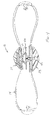
FIG. 2 is a perspective view of the embodiment ofFig. 1 shown in its compressed condition; -
FIG. 3 is a cross-sectional view of the embodiment ofFig. 1 ; -
FIG. 4 is a cross-sectional view of the embodiment ofFig. 2 ; and -
FIG. 5 shows the flight path of the invention as it changes from the configuration ofFig. 2 into the configuration ofFig. 1 , while in flight. - Although the present invention collapsible throwing toy can be made round, it also can be made oblong to mimic the shape of a football. In the exemplary embodiment of the present invention, the collapsible throwing toy is configured into the shape of a football. Such a shape is exemplary and it will be understood that "balls" of geometric shapes other than spherical are intended to be included within the scope of the invention.
- Referring to
Fig. 1 , an exemplary embodiment of acollapsible throwing toy 10 is shown. Thecollapsible throwing toy 10 has anoblong body 12 that is made from a variety ofarcuate sections 14. The differentarcuate sections 14 that comprise thespherical body 12 are symmetrically disposed around acentral axis 20. - Two
end hub assemblies end hub assemblies oblong body 12. Bothend hub assemblies central axis 20 of thecollapsible throwing toy 10. The plurality of collapsiblearcuate sections 14 extend between the twoend hub assemblies arcuate sections 14 are shown. However, such a configuration is merely exemplary and it should be understood that any plurality of collapsiblearcuate sections 14 can be used. - Each of the collapsible
arcuate sections 14 contains an upper panel 16, alower panel 18 and ajoint element 26. If theend hub assemblies central axis 20 at different pole ends of theoblong body 12, animaginary mid-plane 24 exists between theend hub assemblies oblong body 12, dividing theoblong body 12 into anupper half 28 and alower half 29. Thejoint elements 26 of each of the collapsiblearcuate sections 14 are disposed along the mid-plane 24. The upper panel 16 of each collapsiblearcuate section 14 extends in theupper half 28 of theoblong body 12, above the mid-plane 24. Conversely, thelower panel 18 of each collapsiblearcuate section 14 extends in thelower half 29 of theoblong body 12, below the mid-plane 24. - As will later be more fully described, a suction cup is disposed inside the
spherical body 12 of thecollapsible throwing toy 10 behind the upperend hub assembly 21. A surface that can be temporarily engaged by the suction cup is disposed inside thespherical body 12 of thecollapsible throwing toy 10 behind the opposite lowerend hub assembly 22. - The
arcuate sections 14 that form theoblong body 12 of thecollapsible throwing toy 10 are made to fold at thejoint elements 26 along themid-plane plane 24. However, as will be further explained, the variousarcuate sections 14 are engaged by an elastic band that causes thearcuate sections 14 not to bend unless forced to do so. This maintains thecollapsible throwing toy 10 in its expanded shape, as is illustrated inFig. 1 . - Stabilizing
fins 27 are present on the exterior of theelongated body 12. The stabilizingfins 27 help theoblong body 12 fly in a straight spiral when thecollapsible throwing toy 10 is in flight in its expanded shape. - Referring to
Fig. 2 in conjunction withFig. 1 , it can be seen that theoblong body 12 of thecollapsible throwing toy 10 can be altered into a disc shape by pressing the twoend hub assemblies end hub assemblies imaginary mid-plane 24 of theoblong body 12. As the twoend hub assemblies end hub assembly 21 temporarily engages the opposing lowerend hub assembly 22, As the upper andlower halves oblong body 12 are compressed, the collapsiblearcuate sections 14 fold at thejoint elements 26. The oblong shape ofFig. 1 , therefore transforms into the disc shape ofFig. 2 . - When in the disc shape, the stabilizing
fins 27 fold down flat against the compressedarcuate sections 14. In this manner, the stabilizingfins 27 do not adversely affect the ability of thecollapsible throwing toy 10 to be thrown like a disc while in its collapsed shape. - As the various collapsible
arcuate sections 14 fold, they each resist the folding deformation with a spring bias. The combined bias of all the collapsiblearcuate sections 14 creates a force that opposes the compression. This bias causes the collapsiblearcuate sections 14 to immediately pop back into an expanded shape the instant the compression force is released or the twoend hub assemblies - Referring to
Fig. 3 , it can be seen that anelastic band 42 is joined to all of thearcuate sections 14 inside theoblong body 12. Theelastic band 42 travels in the same plane as the mid-plane 24 and connects to the inside of eachjoint element 26. This biases eachjoint element 26 toward thecentral axis 20. This bias direction causes theoblong body 12 to stand in its expanded shape. When theelongated body 12 is compressed, the diameter around the mid-plane 24 expands. This causes theelastic band 42, to stretch and store energy. Due to the pull of theelastic band 42, theoblong body 12 would immediately snap back into its expanded shape should the compression forces be removed. The bias of theelastic band 42 is resisted by the engagement of the upperend hub assembly 21 and the lowerend hub assembly 22 when theoblong body 12 is fully collapsed. - The use of an
elastic band 42 to bias theoblong body 12 into its expanded shape is only exemplary. Other bias systems exist that can be adapted for use in the present invention. Another such bias system is described inU.S. Patent No. 6,896,577 to Feng , entitled Configuration For A Collapsible Throwing Toy And Its Associated Method Of Manufacture, the disclosure of which is incorporated into this specification by reference. - Returning to
Fig. 3 , the structure of the upperend hub assembly 21 and the lowerend hub assembly 22 are also shown. The upperend hub assembly 21 has anexternal plate 30 that lay on the exterior apex of theupper half 28 of theoblong body 12. The upperend hub assembly 21 also has aninternal plate 32 that lay on the interior. A weight compartment is provided that holds aweight 36. Theweight 36 is used to improve the flight characteristics of thecollapsible throwing toy 10, as will later be explained. Asuction cup 40 extends below theweight 36. Thesuction cup 40 faces inwardly toward the mid-plane 24. Furthermore, thesuction cup 40 is aligned with thecentral axis 20 of thecollapsible throwing toy 10. - An
end cap 38 attaches to theexternal plate 30 of the upperend hub assembly 21. Theend cap 38 has a curved exterior that complements the curvature of the exterior of theoblong body 12. - The lower
end hub assembly 22 includes aflat attachment plate 44. Theattachment plate 44 has aflat surface 45 that thesuction cup 40 attaches to when thecollapsible throwing toy 10 is collapsed. Avent hole 46 is disposed through theattachment plate 44. Thevent hole 46 enables air to flow in between thesuction cup 40 and theattachment plate 44 when thesuction cup 40 is connected to theflat surface 45 of theattachment plate 44. If thevent hole 46 were left open, no suction could develop between thesuction cup 40 and theattachment plate 44. Thesuction cup 40 would, therefore, only remain attached to theattachment plate 44 for a moment. In order to control the flow of air through thevent hole 46, avent valve assembly 50 is provided. - The
vent valve assembly 50 includes avalve needle 52 that extends into thevent hole 46. Thevalve needle 52 has the ability to completely seal thevent hole 46 or selectively allow controlled volumes of air to flow through thevent hole 46. The degree by which thevalve needle 52 blocks thevent hole 46 depends upon the distance that thevalve needle 52 is inserted into thevalve hole 46. - The
valve needle 52 is connected to a threadedrod 54. The threadedrod 54 is connected to a manual control knob 56. The threadedrod 54 engages theattachment plate 44. Accordingly, it will be understood that as the manual control knob 56 is turned, the threadedrod 54 will move up or down in relation to theattachment plate 44. The depth at which thevalve needle 52 is positioned in thevent hole 46 can therefore be selectively controlled by turning the manual control knob 56. - The
suction cup 40 of the upperend hub assembly 21 will only remain attached to theattachment plate 44 of the lowerend hub assembly 22 for as long as the air pressure inside thesuction cup 40 is lower than ambient pressure. Since thevalve assembly 50 enables the amount of air that flows through thevent hole 46 to be controlled, the amount of time that thesuction cup 40 engages theattachment plate 44 can be selectively controlled. If thevalve assembly 50 is used to close thevent hole 46, thesuction cup 40 may remain engaged with theattachment plate 44 for a few minutes. However, if thevalve assembly 50 is opened, air is permitted to flow between thesuction cup 40 and theattachment plate 44. This quickly eliminates any pressure differential that may exist inside thesuction cup 40 and thesuction cup 40 may only adhere to theattachment plate 44 for a second or two. Attachment time between thesuction cup 40 and theattachment plate 44 can therefore be altered as desired from as short as a few seconds to as long as a few minutes. As soon as thesuction cup 40 releases, the force of theelastic band 42 causes the upperend hub assembly 21 and the lowerend hub assembly 22 to separate as theoblong body 12 returns to its expanded shape. - Referring to
Fig. 4 , it will now be understood that when the upper and lowerend hub assemblies arcuate sections 14 fold and thesuction cup 40 contacts and engages theattachment plate 44. The connection between thesuction cup 40 and theattachment plate 44 is temporary as air seeps into thesuction cup 40. The upper and lowerend hub assemblies elastic band 42 on the collapsiblearcuate sections 14. As soon as thesuction cup 40 releases, thecollapsible throwing toy 10 instantly pops back into its ball-like shape. The rate that air seeps into thesuction cup 40 is largely determined by the manual setting made for thevalve assembly 50, via the control knob 56. A person can therefore adjust thevalve assembly 50 to either allow for the quick seepage of air or the slow seepage of air. This directly translates into the time that thesuction cup 40 remains engaged with theattachment plate 44. A person can therefore adjust thecollapsible throwing toy 10 so that it remains collapsed for anywhere from a few seconds to a few minutes. - In the present invention, an oblong shaped ball, like a football, is illustrated. Referring to
Fig. 5 , it can be seen that the method of play for such a toy is that thecollapsible throwing toy 10 is collapsed and thrown as a disc. Thecollapsible throwing toy 10 is adjusted so that it pops into its football shape during flight. In order for thecollapsible throwing toy 10 to fly in a stable manner when collapsed, it must fly while spinning with itscentral axis 20 oriented generally in the vertical. However, when thecollapsible throwing toy 10 pops back into its expanded shape, it only experiences stable flight if it is spinning with itscentral axis 20 generally oriented in the horizontal. - The tilting of the
central axis 20 from the vertical to the horizontal when the collapsed body pops is accomplished in two ways. First, the stabilizingfins 27 on theoblong body 12 extend when thecollapsible throwing toy 10 pops into its expanded shape. The stabilizingfins 27 catch air and cause the orientation of thecollapsible throwing toy 10 to change. Furthermore, the stabilizingfins 27 are preferably curved so that they add spin to thecollapsible throwing toy 10 as thecollapsible throwing toy 10 flies through the air. - The second feature that helps the
collapsible throwing toy 10 reorient in flight is theinternal weights 36 in the upperend hub assembly 21. When thecollapsible throwing toy 10 is collapsed, theweights 36 are very near the geometric center of thecollapsible throwing toy 10. As such, thecollapsible throwing toy 10 has a center of gravity that is very close to its geometric center. This enables thecollapsible throwing toy 10 to remain stable in flight. However, once thecollapsible throwing toy 10 pops back to its expanded shape, theweights 36 are located at the upper end of theoblong body 12, far away from the geometric center of thecollapsible throwing toy 10. This causes the center of gravity to be offset from the path of flight. Wind resistance will therefore act to reorient thecollapsible throwing toy 10 so that both the center of gravity and the geometric center of thecollapsible throwing toy 10 are both aligned along the path of flight. - It will be understood that the embodiment of the present invention collapsible throwing toy that is described and illustrated herein are merely exemplary and a person skilled in the art can make many variations to the embodiment shown without departing from the scope of the present invention. All such variations, modifications and alternate embodiments are intended to be included within the scope of the present invention as defined by the appended claims.
Claims (17)
- A time release suction cup connection assembly, comprising:a suction cup;a flat surface, wherein said suction cup connects said flat surface when presses against said flat surface;a vent hole communicating with said flat surface that enables air to flow between said flat surface and said suction cup when said suction cup is connected to said flat surface;a valve for selectively restricting said vent hole, wherein said valve controls airflow through said vent hole.
- The assembly according to Claim 1, further including at least one biasing element that biases said suction cup away from said flat surface.
- The assembly according to Claim 1, wherein said suction cup and said flat surface are disposed at opposite sides of a collapsible ball.
- A collapsible throwing toy assembly, comprising:a body that can be selectively configured between an expanded shape and a compressed shape, said body being comprised of a plurality of arcuate sections symmetrically disposed around a central axis;at least one biasing element for biasing said arcuate sections into said expanded shape;a suction cup disposed in said body at a first end of said body;a flat surface disposed in said body at a second end opposite said first end, wherein said suction cup engages said flat surface only when said body is in said compressed shape;a vent valve for venting air through said flat surface between said flat surface and said suction cup when said suction cup engages said flat surface.
- The assembly according to Claim 4, wherein said vent valve is adjustable and selectively controls air flow between said flat surface and said suction cup.
- The assembly according to Claim 5, wherein said vent valve is selectively adjusted by a knob control that is manually accessible on said body.
- The assembly according to Claim 4, wherein said body is oblong in shape.
- The assembly according to Claim 4, further including weights disposed in said body proximate said first end.
- The assembly according to Claim 8, further including stabilizing fins attached to some of said arcuate sections proximate said second end.
- The assembly according to Claim 9, wherein said stabilizing fins are curved and cause said body to rotate when said body is flying in said expanded shape.
- The assembly according to Claim 4, wherein an imaginary mid-plane bisects said body, said mid-plane being perpendicular to said central axis and intersecting each of said arcuate sections.
- The assembly according to Claim 11, wherein said biasing element includes at least one elastic band that interconnects with each of said arcuate sections proximate said mid-plane.
- The assembly according to Claim 12, wherein each of said arcuate sections includes an upper panel and a lower panel that are joined with a hinged connection along said mid-plane.
- A method of forming a collapsible toy that coverts between an expanded shape and a collapsed shape, said method comprising the steps of:providing a plurality of arcuate sections;joining said arcuate sections to form a body that has a central axis and a mid-plane perpendicular to said central axis;providing at least one biasing element that biases said plurality of arcuate sections into said expanded shape;providing a suction cup and an attachment plate to opposing internal areas inside said body, wherein said suction cup temporarily affixes to said attachment plate when said body is compressed into said collapsed shape and said suction cup and said attachment plate are brought into abutment;providing a vent valve that vents air between said suction cup and said body at a controlled rate.
- The method according to Claim 14, wherein said body is oblong when in said expanded shape.
- The method according to Claim 14, further including the step of providing weights in said body at a first end.
- The assembly according to Claim 14, further including attaching stabilizing fins to some of said arcuate sections.
Applications Claiming Priority (1)
| Application Number | Priority Date | Filing Date | Title |
|---|---|---|---|
| US80186707A | 2007-05-13 | 2007-05-13 |
Publications (1)
| Publication Number | Publication Date |
|---|---|
| EP1992391A1 true EP1992391A1 (en) | 2008-11-19 |
Family
ID=39639832
Family Applications (1)
| Application Number | Title | Priority Date | Filing Date |
|---|---|---|---|
| EP08154301A Withdrawn EP1992391A1 (en) | 2007-05-13 | 2008-04-10 | Collapsible throwing toy having timed release mechanism |
Country Status (3)
| Country | Link |
|---|---|
| EP (1) | EP1992391A1 (en) |
| JP (1) | JP2008279257A (en) |
| AU (1) | AU2008202066A1 (en) |
Cited By (2)
| Publication number | Priority date | Publication date | Assignee | Title |
|---|---|---|---|---|
| US20160346628A1 (en) * | 2015-05-28 | 2016-12-01 | Tucker International Llc | Toy Assembly that Converts Between a Spherical Shape and a Flying Disc Shape |
| RU2728852C1 (en) * | 2020-01-17 | 2020-07-31 | Общество с ограниченной ответственностью "ШИКО" | Variable volume device |
Citations (7)
| Publication number | Priority date | Publication date | Assignee | Title |
|---|---|---|---|---|
| US434457A (en) | 1890-08-19 | Electrode for batteries and the method of making the same | ||
| US4196882A (en) * | 1977-11-14 | 1980-04-08 | Rognon Robert Y | Double suction cup holder with vacuum control valve |
| US4955841A (en) * | 1989-11-03 | 1990-09-11 | Anthony Pastrano | Disc-shaped throwing toy |
| US5511752A (en) * | 1994-06-02 | 1996-04-30 | Trethewey; Brig E. A. | Suction cup with valve |
| US5797815A (en) | 1997-02-06 | 1998-08-25 | Goldman Toy Group, Inc. | Pop-open throwing toy with controllable opening delay and method of operating same |
| US6863588B1 (en) * | 2003-12-01 | 2005-03-08 | Kwong Wing Chu | Collapsible throwing toy and its associated method of manufacture |
| US6896577B1 (en) | 2004-02-17 | 2005-05-24 | Jung Chung Feng | Configuration for a collapsible throwing toy and its associated method of manufacture |
-
2008
- 2008-04-10 EP EP08154301A patent/EP1992391A1/en not_active Withdrawn
- 2008-05-09 JP JP2008123506A patent/JP2008279257A/en active Pending
- 2008-05-09 AU AU2008202066A patent/AU2008202066A1/en not_active Abandoned
Patent Citations (7)
| Publication number | Priority date | Publication date | Assignee | Title |
|---|---|---|---|---|
| US434457A (en) | 1890-08-19 | Electrode for batteries and the method of making the same | ||
| US4196882A (en) * | 1977-11-14 | 1980-04-08 | Rognon Robert Y | Double suction cup holder with vacuum control valve |
| US4955841A (en) * | 1989-11-03 | 1990-09-11 | Anthony Pastrano | Disc-shaped throwing toy |
| US5511752A (en) * | 1994-06-02 | 1996-04-30 | Trethewey; Brig E. A. | Suction cup with valve |
| US5797815A (en) | 1997-02-06 | 1998-08-25 | Goldman Toy Group, Inc. | Pop-open throwing toy with controllable opening delay and method of operating same |
| US6863588B1 (en) * | 2003-12-01 | 2005-03-08 | Kwong Wing Chu | Collapsible throwing toy and its associated method of manufacture |
| US6896577B1 (en) | 2004-02-17 | 2005-05-24 | Jung Chung Feng | Configuration for a collapsible throwing toy and its associated method of manufacture |
Cited By (3)
| Publication number | Priority date | Publication date | Assignee | Title |
|---|---|---|---|---|
| US20160346628A1 (en) * | 2015-05-28 | 2016-12-01 | Tucker International Llc | Toy Assembly that Converts Between a Spherical Shape and a Flying Disc Shape |
| US10112121B2 (en) * | 2015-05-28 | 2018-10-30 | Tucker International Llc | Toy assembly that converts between a spherical shape and a flying disc shape |
| RU2728852C1 (en) * | 2020-01-17 | 2020-07-31 | Общество с ограниченной ответственностью "ШИКО" | Variable volume device |
Also Published As
| Publication number | Publication date |
|---|---|
| AU2008202066A1 (en) | 2008-12-04 |
| JP2008279257A (en) | 2008-11-20 |
Similar Documents
| Publication | Publication Date | Title |
|---|---|---|
| US10112121B2 (en) | Toy assembly that converts between a spherical shape and a flying disc shape | |
| US7914405B1 (en) | Collapsible pet toy having timed pop back action | |
| US7927177B1 (en) | Pop action toy ball | |
| US7803033B1 (en) | Pop action toy | |
| US6752682B1 (en) | Hand-launched toy rocket | |
| US7806746B2 (en) | Novelty device having braided sleeve body and its associated method of operation | |
| US6863588B1 (en) | Collapsible throwing toy and its associated method of manufacture | |
| US11988483B2 (en) | Slingshot football | |
| US6896577B1 (en) | Configuration for a collapsible throwing toy and its associated method of manufacture | |
| JP2005518258A (en) | A practice sports flying object with a through hole | |
| US5577732A (en) | Toy missile | |
| US20020164921A1 (en) | Jumping, leaping toy | |
| US4204359A (en) | Flying toy | |
| US3916560A (en) | Miniature aircraft and launcher unit therefor | |
| AU2008202066A1 (en) | Collapsible throwing toy having timed release mechanism | |
| TW201838699A (en) | Unistructural Pop-Up Half Ball Toy | |
| US5863250A (en) | Aerial toy | |
| US3467385A (en) | Boomerang | |
| US12303801B2 (en) | Transformable spherical ball toy | |
| US20220111302A1 (en) | Toy Projectile with Vented Suction Cup Head | |
| US7166037B2 (en) | Golf training apparatus | |
| CN208493222U (en) | Functional rotating toy | |
| US20060009319A1 (en) | Sports ball device with internal noise maker | |
| US6030303A (en) | Tethered ball construction | |
| US6443792B1 (en) | Mechanically launched monowing toy |
Legal Events
| Date | Code | Title | Description |
|---|---|---|---|
| PUAI | Public reference made under article 153(3) epc to a published international application that has entered the european phase |
Free format text: ORIGINAL CODE: 0009012 |
|
| AK | Designated contracting states |
Kind code of ref document: A1 Designated state(s): AT BE BG CH CY CZ DE DK EE ES FI FR GB GR HR HU IE IS IT LI LT LU LV MC MT NL NO PL PT RO SE SI SK TR |
|
| AX | Request for extension of the european patent |
Extension state: AL BA MK RS |
|
| AKX | Designation fees paid | ||
| REG | Reference to a national code |
Ref country code: DE Ref legal event code: 8566 |
|
| STAA | Information on the status of an ep patent application or granted ep patent |
Free format text: STATUS: THE APPLICATION IS DEEMED TO BE WITHDRAWN |
|
| 18D | Application deemed to be withdrawn |
Effective date: 20090520 |