EP1992266A2 - Vacuum cleaner - Google Patents
Vacuum cleaner Download PDFInfo
- Publication number
- EP1992266A2 EP1992266A2 EP20080001202 EP08001202A EP1992266A2 EP 1992266 A2 EP1992266 A2 EP 1992266A2 EP 20080001202 EP20080001202 EP 20080001202 EP 08001202 A EP08001202 A EP 08001202A EP 1992266 A2 EP1992266 A2 EP 1992266A2
- Authority
- EP
- European Patent Office
- Prior art keywords
- air
- dust
- dust collecting
- filter
- vacuum cleaner
- Prior art date
- Legal status (The legal status is an assumption and is not a legal conclusion. Google has not performed a legal analysis and makes no representation as to the accuracy of the status listed.)
- Withdrawn
Links
Images



Classifications
-
- A—HUMAN NECESSITIES
- A47—FURNITURE; DOMESTIC ARTICLES OR APPLIANCES; COFFEE MILLS; SPICE MILLS; SUCTION CLEANERS IN GENERAL
- A47L—DOMESTIC WASHING OR CLEANING; SUCTION CLEANERS IN GENERAL
- A47L9/00—Details or accessories of suction cleaners, e.g. mechanical means for controlling the suction or for effecting pulsating action; Storing devices specially adapted to suction cleaners or parts thereof; Carrying-vehicles specially adapted for suction cleaners
- A47L9/009—Carrying-vehicles; Arrangements of trollies or wheels; Means for avoiding mechanical obstacles
-
- A—HUMAN NECESSITIES
- A47—FURNITURE; DOMESTIC ARTICLES OR APPLIANCES; COFFEE MILLS; SPICE MILLS; SUCTION CLEANERS IN GENERAL
- A47L—DOMESTIC WASHING OR CLEANING; SUCTION CLEANERS IN GENERAL
- A47L7/00—Suction cleaners adapted for additional purposes; Tables with suction openings for cleaning purposes; Containers for cleaning articles by suction; Suction cleaners adapted to cleaning of brushes; Suction cleaners adapted to taking-up liquids
- A47L7/02—Suction cleaners adapted for additional purposes; Tables with suction openings for cleaning purposes; Containers for cleaning articles by suction; Suction cleaners adapted to cleaning of brushes; Suction cleaners adapted to taking-up liquids with driven tools for special purposes
-
- A—HUMAN NECESSITIES
- A47—FURNITURE; DOMESTIC ARTICLES OR APPLIANCES; COFFEE MILLS; SPICE MILLS; SUCTION CLEANERS IN GENERAL
- A47L—DOMESTIC WASHING OR CLEANING; SUCTION CLEANERS IN GENERAL
- A47L9/00—Details or accessories of suction cleaners, e.g. mechanical means for controlling the suction or for effecting pulsating action; Storing devices specially adapted to suction cleaners or parts thereof; Carrying-vehicles specially adapted for suction cleaners
- A47L9/02—Nozzles
- A47L9/04—Nozzles with driven brushes or agitators
-
- A—HUMAN NECESSITIES
- A47—FURNITURE; DOMESTIC ARTICLES OR APPLIANCES; COFFEE MILLS; SPICE MILLS; SUCTION CLEANERS IN GENERAL
- A47L—DOMESTIC WASHING OR CLEANING; SUCTION CLEANERS IN GENERAL
- A47L2201/00—Robotic cleaning machines, i.e. with automatic control of the travelling movement or the cleaning operation
Definitions
- the present disclosure relates to a vacuum cleaner. More particularly, the present disclosure relates to a vacuum cleaner having an air suction and rotation unit with a bypass passage structure in which air does not directly pass through a motor, but bypasses the motor.
- a vacuum cleaner is provided with a suction motor, which generates a suction force to draw in air laden with dust or dirt through an air inflow opening.
- the suction motor is usually disposed downstream of a dust collecting unit having a filter to filter the dust or dirt included in the drawn-in air. Accordingly, the air laden with the dust or dirt drawn in by the suction force of the suction motor passes through the dust collecting unit to remove the dust or dirt therefrom, moves to and passes through the suction motor, and then discharges to the outside through a filter disposed in an air outflow opening.
- the conventional vacuum cleaner is disadvantageous in that if the dust or dirt accumulated in the filter of the dust collecting unit chokes the filter, the suction force of the suction motor is reduced and thus a dust-separating efficiency of the vacuum cleaner is lowered.
- a reduction of the suction force results in more fatal lowering of the dust-separating efficiency, as compared with a general vacuum cleaner, because it uses a battery of low voltage as a power of the suction motor.
- the suction motor is not disposed just adjacent to the air inflow opening for drawing in the air, but interposing the dust collecting unit therebetween, the dust or dirt adhered to a surface to be cleaned does not directly suffer the suction force of the suction motor. As a result, the dust suction efficiency, which is capable of drawing in the dust or dirt through the air inflow opening, is lowered.
- the suction motor does not separate the dust or dirt from the air in combination with the dust collecting unit, but it acts to provide only the suction force to draw in the air through the air inflow opening thus to move it to the dust collecting unit. Accordingly, the dust-separating efficiency depends on only a dust separating performance of the dust collecting unit.
- a vacuum cleaner in which a suction force of a suction device, such as the vacuum motor, is not largely reduced even though the filter is choked with the dust or dirt, the suction force is applied directly to the air inflow opening, and the suction device is capable of separating the dust or dirt from the air in combination with the dust collecting unit.
- a suction force of a suction device such as the vacuum motor
- an aspect of the present disclosure is to address at least the above problems and/or disadvantages and to provide at least the advantages described below. Accordingly, an aspect of the present disclosure is to provide a vacuum cleaner having an improved structure to drive a suction device with a relatively low voltage and not to largely reduce a suction force even though a filter is choked with dust or dirt.
- Another aspect of the present disclosure is to provide a vacuum cleaner having an improved structure to apply a suction force of a suction device directly to an air inflow opening, thereby allowing the vacuum cleaner to increase a dust suction efficiency.
- FIG. 1 Another aspect of the present disclosure is to provide a vacuum cleaner having a suction device capable of separating dust or dirt in combination with a dust collecting unit.
- a vacuum cleaner includes a cleaner body having an air inflow opening and an air outflow opening, at least one air suction and rotation unit disposed downstream of a drum brush installed in the air inflow opening, to draw in air through the air inflow opening and at the same time, to rotate the air, and a dust collecting unit disposed downstream of the air suction and rotation unit and having a dust collecting chamber to separate and collect dust or dirt from the air by a centrifugal force and an air flow generated by the air suction and rotation unit.
- the cleaner body may be a cleaner body of a general vacuum cleaner or a robot vacuum cleaner.
- the air suction and rotation unit may include an impeller disposed adjacent to the drum brush downstream of the drum brush, and a motor connected with the impeller to drive the impeller.
- the motor is formed of a direct current (DC) motor.
- the dust collecting chamber may include a first dust collecting space to first collect dust or dirt from the air, a first filter disposed downstream of the first dust collecting space to filter dust or dirt, a second dust collecting space to secondly collect dust or dirt from the air past the first filter, and a second filter disposed between the second dust collecting space and the air outflow opening to filter dust or dirt.
- the first filter is formed of a mesh filter
- the second filter is formed of a sponge type filter, a high efficiency particulate arrestor (HEPA) filter, or a combination thereof.
- HEPA high efficiency particulate arrestor
- FIGS. 1 and 2 are a side cross-sectional view and a top plan cross-sectional view exemplifying a robot vacuum cleaner as an example of a vacuum cleaner according to an exemplary embodiment of the present disclosure.
- the robot cleaner 10 includes a cleaner body 11, an air suction and rotation unit 30, and a dust collecting unit 40.
- the cleaner body 11 has an air inflow opening 13 formed in bottom surface of the rear of thereof.
- the air inflow opening 13 is communicated with an air inflow guide 17 of the air suction and rotation unit 30, and formed in a size capable of exposing a portion of a drum brush 15 to the outside, so that the drum brush 15 can brush away dust or dirt from a surface to be cleaned.
- the cleaner body 11 at a rear surface thereof has an air outflow opening 21.
- the air outflow opening 21 is formed to communicate with a second dust collecting space 45 of a dust collecting chamber 42 of a dust collecting bin 41, which will be described.
- an air passage which is defined by the air inflow guide 17 of the air suction and rotation unit 30 and the dust collecting chamber 42 of the dust collecting bin 41.
- the cleaner body 11 are mounted a photographing unit (not illustrated) to sense a position of the robot cleaner 10 and obstacles, a driving unit (not illustrated) to drive wheels 19 thus to move the cleaner body 11, and a battery (not illustrated) to supply a power to the driving unit. Accordingly, the robot cleaner 10 can move while confirming its own position and the obstacles by using the components as described above.
- the photographing unit, the driving unit and the battery are the same as those of the convention robot vacuum cleaner, a detailed description on constructions thereof will be omitted.
- the air suction and rotation unit 30 draws in air through the air inflow opening 13 and at the same time, supplies the air to the dust collecting unit 40 while rotating the air.
- the air suction and rotation unit 30 is disposed in the air inflow guide 17 located adjacent to the air inflow opening 13, and has an impeller 31 and a motor 33.
- the impeller 31 is disposed in the air inflow guide 17.
- the impeller 31 changes a flowing direction of the air flowing through an inlet 17a of the air inflow guide 17 in an angle of 90 degrees and discharges the drawn-in air toward a first dust collecting space 43 of the dust collecting chamber 42 through an outlet 17b.
- relatively large dust or dirt included in the air is moved into the first dust collecting space 43 while being centrifugally separated from the air by the centrifugal force generated by the rotation of the impeller 31.
- the motor 33 is connected with the impeller 31 outside the air inflow guide 17, so that it provides a bypass passage structure in which air does not directly pass through the motor, but bypasses the motor.
- the motor 33 can use a small and low-priced direct current (DC) motor, which is driven with a relatively low voltage.
- DC direct current
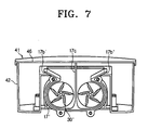
- an air suction and rotation unit 30 can be made up of two impellers 31 a and 31 b and two motors 33a and 33b, which are symmetrically disposed to each other, respectively.
- an air inflow guide 17' is configured, so that two inlets (not illustrated) and two outlets 17b' and 17b" form two air passages, which are bilaterally symmetrical on an intermediate partition 17c.
- the dust collecting unit 40 is disposed downstream of the air suction and rotation unit 30 to separate the dust or dirt in combination therewith.
- the dust collecting unit 40 has a dust collecting bin 41, which separates and collects the dust or dirt from the air by using the centrifugal force and the air flow generated by the air suction and rotation unit 30.
- the dust collecting bin 41 is detachably installed to the cleaner body 11.
- the dust collecting bin 41 is provided with a cover 46 and a dust collecting chamber 42.
- the cover 46 closes up the dust collecting chamber 42.
- the cover 46 is detachably joined to the dust collecting chamber 42 to open and close the dust collecting chamber 42.
- the dust collecting chamber 42 has an opening 42a formed in a lower part of the front thereof to join with the outlet 17b of the air inflow guide 17.
- the dust collecting chamber 42 is provided with a first dust collecting space 43, a first filter 47, a second dust collecting space 45 and a second filter 48.
- the first dust collecting space 43 first separates and collects dust or dirt from the air by the centrifugal force and the air flow generated by the rotation of the impeller 31. That is, as illustrated in FIGS. 3 and 4B , relatively large dust or dirt is first separated from the air by the centrifugal force generated by the rotation of the impeller 31 of the air suction and rotation unit 30, and then collected in the first dust collecting space 43 by its own weight. In addition, relatively minute dust or dirt is first separated from the air by the air flow discharged through the outlet 17b of the air inflow guide 17, and then collected in the first dust collecting space 43 by its own weight. At this time, if the impeller 31 is rotated in the number of rotations of, for example, 4,000 rpm, a maximum flowing speed of the air is 15 meters per second (m/sec).
- the first filter 47 first filters dust or dirt, which is not collected into the first dust collecting space 43, from the air.
- the first filter 47 is disposed between the first dust collecting space 43 and the second dust collecting space 45.
- the first filter 47 is formed of a mesh filter in the form of a net.
- the second dust collecting space 45 secondly separates and collects dust or dirt from the air past the first filter 47 by means of a weight of the dust or dirt. That is, relatively large dust or dirt, which is not collected and filtered through the first dust collecting space 43 and the first filter 47, is secondly separated from the air by the remaining centrifugal force and then collected in the second dust collecting space 45 by its own weight. In addition, relatively minute dust or dirt, which is not collected and filtered through the first dust collecting space 43 and the first filter 47, is secondly separated from the air by the air flow and then collected in the second dust collecting space 45 by its own weight.
- the second filter 48 secondly filters dust or dirt, which is not collected into the second dust collecting space 45, from the air and discharges the filtered air to the outside.
- the second filter 48 is disposed between the second dust collecting space 45 and the air outflow opening 21 in a rear surface of the dust collecting chamber 42.
- the second filter 48 can be formed of a sponge type filter, a high efficiency particulate arrestor (HEPA) filter, or a combination thereof, which have filtering holes formed not to have influence on the suction force of the impeller 31.
- HEPA high efficiency particulate arrestor
- the dust collecting chamber 42 of the dust collecting bin 41 separates the dust or dirt from the air in combination with the impeller 31, and additionally filters the dust or dirt from the air through the first and the second filters 47 and 48. Accordingly, the dust-separating efficiency can be more improved.
- the vacuum cleaner according to the exemplary embodiment of the present disclosure is explained and illustrated as applied to the robot vacuum cleaner 10, the present disclosure is not limited thereto.
- the vacuum cleaner according to the exemplary embodiment of the present disclosure can be applied to a general vacuum cleaner, such as a canister vacuum cleaner, in the same construction and principle.
- the robot cleaner 10 If a cleaning command is issued, the robot cleaner 10 operates the driving unit and the photographing unit to move along a traveling path programmed in advance while avoiding obstacles appearing from the front in real time. During such a traveling, the robot cleaner 10 drives the motor 33 of the air suction and rotation unit 30 mounted therein, so that it carries out a cleaning operation.
- the air laden with the dust or dirt drawn into the air inflow guide 17 is discharged into the first dust collecting space 43 while being rotated by the impeller 31.
- relative large dust or dirt included in the air is moved into the first dust collecting space 43 while being centrifugally separated from the air by the centrifugal force generated by the rotation of the impeller 31.
- relatively large dust or dirt and minute dust or dirt are first separated from the air by the centrifugal force and the air flow generated by the rotation of the impeller 31 and collected into the first dust collecting space 43 by their own weights, respectively.
- the vacuum cleaner is configured, so that the impeller is disposed to draw in the air directly from the air inflow opening downstream of the air inflow opening without any obstacle therebetween.
- the motor can use the small and low-priced direct current (DC) motor, which is driven with the relatively low voltage.
- DC direct current
- the problem which the suction force is decreased due to the choking of the filter of the dust collecting unit generating as the suction motor is disposed downstream of the dust collecting unit as in the conventional vacuum cleaner, and thereby the dust-separating efficiency is deteriorated, is prevented.
- the vacuum cleaner according to the exemplary embodiments of the present disclosure is configured, so that the air suction force generated by the rotation of the impeller is applied directly to the air inflow opening and the drum brush disposed in the air inflow opening. Accordingly, the dust or dirt adhered to the surface to be cleaned directly suffers the air suction force of the impeller. As a result, the dust suction efficiency, which is capable of drawing in the dust or dirt through the air inflow opening, is more improved.
- the vacuum cleaner according to the exemplary embodiments of the present disclosure is configured, so that the dust collecting chamber of the dust collecting bin separates the dust or dirt from the air in combination with the impeller, and additionally filters the dust or dirt from the air through the first and the second filters. Accordingly, the dust-separating efficiency can be more improved.
Landscapes
- Engineering & Computer Science (AREA)
- Mechanical Engineering (AREA)
- Filters For Electric Vacuum Cleaners (AREA)
Abstract
A vacuum cleaner having a suction and rotation unit (30) with a bypass passage structure in which air does not directly pass through a motor (33), but bypasses the motor is disclosed. The vacuum cleaner includes a cleaner body (11) having an air inflow opening (13) and an air outflow opening (21), at least one air suction and rotation unit (30) disposed downstream of a drum brush (15) installed in the air inflow opening (13), to draw in air through the air inflow opening and at the same time, to rotate the air, and a dust collecting unit (40) disposed downstream of the air suction and rotation unit (30) and having a dust collecting chamber (42) to separate and collect dust or dirt from the air by a centrifugal force and an air flow generated by the air suction and rotation unit (30).
Description
- The present disclosure relates to a vacuum cleaner. More particularly, the present disclosure relates to a vacuum cleaner having an air suction and rotation unit with a bypass passage structure in which air does not directly pass through a motor, but bypasses the motor.
- In general, a vacuum cleaner is provided with a suction motor, which generates a suction force to draw in air laden with dust or dirt through an air inflow opening. The suction motor is usually disposed downstream of a dust collecting unit having a filter to filter the dust or dirt included in the drawn-in air. Accordingly, the air laden with the dust or dirt drawn in by the suction force of the suction motor passes through the dust collecting unit to remove the dust or dirt therefrom, moves to and passes through the suction motor, and then discharges to the outside through a filter disposed in an air outflow opening.
- However, the conventional vacuum cleaner is disadvantageous in that if the dust or dirt accumulated in the filter of the dust collecting unit chokes the filter, the suction force of the suction motor is reduced and thus a dust-separating efficiency of the vacuum cleaner is lowered. In case of a robot vacuum cleaner, such a reduction of the suction force results in more fatal lowering of the dust-separating efficiency, as compared with a general vacuum cleaner, because it uses a battery of low voltage as a power of the suction motor.
- Further, since the suction motor is not disposed just adjacent to the air inflow opening for drawing in the air, but interposing the dust collecting unit therebetween, the dust or dirt adhered to a surface to be cleaned does not directly suffer the suction force of the suction motor. As a result, the dust suction efficiency, which is capable of drawing in the dust or dirt through the air inflow opening, is lowered.
- Also, the suction motor does not separate the dust or dirt from the air in combination with the dust collecting unit, but it acts to provide only the suction force to draw in the air through the air inflow opening thus to move it to the dust collecting unit. Accordingly, the dust-separating efficiency depends on only a dust separating performance of the dust collecting unit.
- Therefore, there is need for a vacuum cleaner in which a suction force of a suction device, such as the vacuum motor, is not largely reduced even though the filter is choked with the dust or dirt, the suction force is applied directly to the air inflow opening, and the suction device is capable of separating the dust or dirt from the air in combination with the dust collecting unit.
- An aspect of the present disclosure is to address at least the above problems and/or disadvantages and to provide at least the advantages described below. Accordingly, an aspect of the present disclosure is to provide a vacuum cleaner having an improved structure to drive a suction device with a relatively low voltage and not to largely reduce a suction force even though a filter is choked with dust or dirt.
- Another aspect of the present disclosure is to provide a vacuum cleaner having an improved structure to apply a suction force of a suction device directly to an air inflow opening, thereby allowing the vacuum cleaner to increase a dust suction efficiency.
- Further another aspect of the present disclosure is to provide a vacuum cleaner having a suction device capable of separating dust or dirt in combination with a dust collecting unit.
- In accordance with an aspect of the present disclosure, a vacuum cleaner includes a cleaner body having an air inflow opening and an air outflow opening, at least one air suction and rotation unit disposed downstream of a drum brush installed in the air inflow opening, to draw in air through the air inflow opening and at the same time, to rotate the air, and a dust collecting unit disposed downstream of the air suction and rotation unit and having a dust collecting chamber to separate and collect dust or dirt from the air by a centrifugal force and an air flow generated by the air suction and rotation unit.
- Here, the cleaner body may be a cleaner body of a general vacuum cleaner or a robot vacuum cleaner.
- The air suction and rotation unit may include an impeller disposed adjacent to the drum brush downstream of the drum brush, and a motor connected with the impeller to drive the impeller. At this time, preferably, but not necessarily, the motor is formed of a direct current (DC) motor.
- The dust collecting chamber may include a first dust collecting space to first collect dust or dirt from the air, a first filter disposed downstream of the first dust collecting space to filter dust or dirt, a second dust collecting space to secondly collect dust or dirt from the air past the first filter, and a second filter disposed between the second dust collecting space and the air outflow opening to filter dust or dirt. At this time, preferably, but not necessarily, the first filter is formed of a mesh filter, and the second filter is formed of a sponge type filter, a high efficiency particulate arrestor (HEPA) filter, or a combination thereof.
- The above and other objects, features, and advantages of certain exemplary embodiments of the present disclosure will be more apparent from the following description taken in conjunction with the accompanying drawings, in which:
-
FIG. 1 is a side cross-sectional view exemplifying a robot vacuum cleaner as an example of a vacuum cleaner according to an exemplary embodiment of the present disclosure; -
FIG. 2 is a top plan cross-sectional view of the robot vacuum cleaner illustrated inFIG. 1 ; -
FIG. 3 is a cross-sectional view taken along line III-III ofFIG. 1 ; -
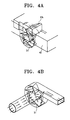
FIGS. 4A and 4B are views exemplifying results of analysis to an air flow caused by an impeller of an air suction and rotation unit of the robot vacuum cleaner illustrated inFIG. 3 ; -
FIG. 5 is a partial perspective view exemplifying a dust collecting chamber of an dust collecting unit of the robot vacuum cleaner illustrated inFIG. 1 ; -
FIG. 6 is a partial perspective view exemplifying another embodiment of the air suction and rotation unit of the robot vacuum cleaner illustrated inFIG. 1 ; and -
FIG. 7 is a cross-sectional view taken along line VII-VII ofFIG. 6 . - Throughout the drawings, the same reference numerals will be understood to refer to the same elements, features, and structures.
- Hereinafter, a vacuum cleaner according to exemplary embodiments of the present disclosure will be described in detail with reference to the accompanying drawing figures.
-
FIGS. 1 and 2 are a side cross-sectional view and a top plan cross-sectional view exemplifying a robot vacuum cleaner as an example of a vacuum cleaner according to an exemplary embodiment of the present disclosure. - As illustrated in
FIGS. 1 and 2 , therobot cleaner 10 includes acleaner body 11, an air suction androtation unit 30, and adust collecting unit 40. - The
cleaner body 11 has anair inflow opening 13 formed in bottom surface of the rear of thereof. Theair inflow opening 13 is communicated with anair inflow guide 17 of the air suction androtation unit 30, and formed in a size capable of exposing a portion of adrum brush 15 to the outside, so that thedrum brush 15 can brush away dust or dirt from a surface to be cleaned. Thecleaner body 11 at a rear surface thereof has an air outflow opening 21. The air outflow opening 21 is formed to communicate with a seconddust collecting space 45 of adust collecting chamber 42 of a dust collectingbin 41, which will be described. Between the air inflow opening 13 and the air outflow opening 21 of thecleaner body 11 is formed an air passage, which is defined by theair inflow guide 17 of the air suction androtation unit 30 and thedust collecting chamber 42 of the dust collectingbin 41. - In addition, in the
cleaner body 11 are mounted a photographing unit (not illustrated) to sense a position of therobot cleaner 10 and obstacles, a driving unit (not illustrated) to drivewheels 19 thus to move thecleaner body 11, and a battery (not illustrated) to supply a power to the driving unit. Accordingly, therobot cleaner 10 can move while confirming its own position and the obstacles by using the components as described above. Here, since the photographing unit, the driving unit and the battery are the same as those of the convention robot vacuum cleaner, a detailed description on constructions thereof will be omitted. - The air suction and
rotation unit 30 draws in air through the air inflow opening 13 and at the same time, supplies the air to thedust collecting unit 40 while rotating the air. For this, the air suction androtation unit 30 is disposed in theair inflow guide 17 located adjacent to theair inflow opening 13, and has animpeller 31 and amotor 33. As illustrated inFIG. 3 , theimpeller 31 is disposed in theair inflow guide 17. Theimpeller 31 changes a flowing direction of the air flowing through aninlet 17a of theair inflow guide 17 in an angle of 90 degrees and discharges the drawn-in air toward a firstdust collecting space 43 of thedust collecting chamber 42 through anoutlet 17b. At this time, as illustrated inFIGS. 4A and 4B , relatively large dust or dirt included in the air is moved into the firstdust collecting space 43 while being centrifugally separated from the air by the centrifugal force generated by the rotation of theimpeller 31. Themotor 33 is connected with theimpeller 31 outside theair inflow guide 17, so that it provides a bypass passage structure in which air does not directly pass through the motor, but bypasses the motor. - Since the
impeller 31 is disposed to draw in the air directly from the air inflow opening 13 downstream of the air inflow opening 13 without any obstacle therebetween as described above, themotor 33 can use a small and low-priced direct current (DC) motor, which is driven with a relatively low voltage. In addition, the problem, which the suction force is decreased due to the choking of the filter of the dust collecting unit generating as the suction motor is disposed downstream of the dust collecting unit as in the conventional vacuum cleaner, and thus the dust-separating efficiency is deteriorated, is prevented. - Also, since the suction force generated by the rotation of the
impeller 31 is applied directly to theair inflow opening 13 and thedrum brush 15 disposed in theair inflow opening 13, the dust or dirt adhered to the surface to be cleaned directly suffers the air suction force of theimpeller 13. As a result, a dust suction efficiency, which is capable of drawing in the dust or dirt through theair inflow opening 13, is increased. - In the above description, although the air suction and
rotation unit 30 is explained and illustrated as made up of asingle impeller 31 and asingle motor 33, the present disclosure is not limited thereto. For instance, as illustrated inFIGS. 6 and7 , to increase an air suction and rotation efficiency, an air suction and rotation unit 30' can be made up of twoimpellers motors outlets 17b' and 17b" form two air passages, which are bilaterally symmetrical on anintermediate partition 17c. - Referring again to
FIG. 1 , thedust collecting unit 40 is disposed downstream of the air suction androtation unit 30 to separate the dust or dirt in combination therewith. Thedust collecting unit 40 has adust collecting bin 41, which separates and collects the dust or dirt from the air by using the centrifugal force and the air flow generated by the air suction androtation unit 30. - The
dust collecting bin 41 is detachably installed to thecleaner body 11. Thedust collecting bin 41 is provided with acover 46 and adust collecting chamber 42. - The
cover 46 closes up thedust collecting chamber 42. Thecover 46 is detachably joined to thedust collecting chamber 42 to open and close thedust collecting chamber 42. - The
dust collecting chamber 42 has anopening 42a formed in a lower part of the front thereof to join with theoutlet 17b of theair inflow guide 17. Thedust collecting chamber 42 is provided with a firstdust collecting space 43, afirst filter 47, a seconddust collecting space 45 and asecond filter 48. - The first
dust collecting space 43 first separates and collects dust or dirt from the air by the centrifugal force and the air flow generated by the rotation of theimpeller 31. That is, as illustrated inFIGS. 3 and4B , relatively large dust or dirt is first separated from the air by the centrifugal force generated by the rotation of theimpeller 31 of the air suction androtation unit 30, and then collected in the firstdust collecting space 43 by its own weight. In addition, relatively minute dust or dirt is first separated from the air by the air flow discharged through theoutlet 17b of theair inflow guide 17, and then collected in the firstdust collecting space 43 by its own weight. At this time, if theimpeller 31 is rotated in the number of rotations of, for example, 4,000 rpm, a maximum flowing speed of the air is 15 meters per second (m/sec). - The
first filter 47 first filters dust or dirt, which is not collected into the firstdust collecting space 43, from the air. Thefirst filter 47 is disposed between the firstdust collecting space 43 and the seconddust collecting space 45. As illustrated inFIG. 5 , thefirst filter 47 is formed of a mesh filter in the form of a net. - The second
dust collecting space 45 secondly separates and collects dust or dirt from the air past thefirst filter 47 by means of a weight of the dust or dirt. That is, relatively large dust or dirt, which is not collected and filtered through the firstdust collecting space 43 and thefirst filter 47, is secondly separated from the air by the remaining centrifugal force and then collected in the seconddust collecting space 45 by its own weight. In addition, relatively minute dust or dirt, which is not collected and filtered through the firstdust collecting space 43 and thefirst filter 47, is secondly separated from the air by the air flow and then collected in the seconddust collecting space 45 by its own weight. - The
second filter 48 secondly filters dust or dirt, which is not collected into the seconddust collecting space 45, from the air and discharges the filtered air to the outside. Thesecond filter 48 is disposed between the seconddust collecting space 45 and the air outflow opening 21 in a rear surface of thedust collecting chamber 42. Thesecond filter 48 can be formed of a sponge type filter, a high efficiency particulate arrestor (HEPA) filter, or a combination thereof, which have filtering holes formed not to have influence on the suction force of theimpeller 31. - As described above, the
dust collecting chamber 42 of thedust collecting bin 41 separates the dust or dirt from the air in combination with theimpeller 31, and additionally filters the dust or dirt from the air through the first and thesecond filters - Although the vacuum cleaner according to the exemplary embodiment of the present disclosure is explained and illustrated as applied to the
robot vacuum cleaner 10, the present disclosure is not limited thereto. For instance, the vacuum cleaner according to the exemplary embodiment of the present disclosure can be applied to a general vacuum cleaner, such as a canister vacuum cleaner, in the same construction and principle. - Hereinafter, an operation of the
robot cleaner 10 according to the exemplary embodiment of the present disclosure constructed as described above will be in detail with reference toFIGS. 1 through 5 . - If a cleaning command is issued, the
robot cleaner 10 operates the driving unit and the photographing unit to move along a traveling path programmed in advance while avoiding obstacles appearing from the front in real time. During such a traveling, therobot cleaner 10 drives themotor 33 of the air suction androtation unit 30 mounted therein, so that it carries out a cleaning operation. - When the
motor 33 is driven, as illustrated inFIG. 1 , external air is drawn into theair inflow guide 17 through theair inflow opening 13 along with dust or dirt brushed away from a surface to be cleaned by thedrum brush 15 rotating according to the traveling of therobot cleaner 10. At this time, since theimpeller 31 is communicated directly with theair inflow opening 13 without any obstacle therebetween, the dust or dirt brushed off by thedrum brush 15 flows into theair inflow guide 17 as maximum as possible. - The air laden with the dust or dirt drawn into the
air inflow guide 17 is discharged into the firstdust collecting space 43 while being rotated by theimpeller 31. At this time, as illustrated inFIGS. 4A and 4B , relative large dust or dirt included in the air is moved into the firstdust collecting space 43 while being centrifugally separated from the air by the centrifugal force generated by the rotation of theimpeller 31. - As illustrated in
FIGS. 3 through 4B , relatively large dust or dirt and minute dust or dirt are first separated from the air by the centrifugal force and the air flow generated by the rotation of theimpeller 31 and collected into the firstdust collecting space 43 by their own weights, respectively. - Subsequently, dust or dirt, which is not collected into the first
dust collecting space 43, is first filtered by thefirst filter 47. - And then, relatively large dust or dirt and minute dust or dirt, which are not collected and filtered by the first
dust collecting space 43 and thefirst filter 47, are secondly separated from the air by the remaining centrifugal force and the remaining air flow and collected into the seconddust collecting space 45 by their own weights, respectively. - After that, dust or dirt, which is not collected into the second
dust collecting space 45, is secondly filtered by thesecond filter 48, and then discharged to the outside through the air outflow opening 21. - As apparent from the foregoing description, according to the exemplary embodiments of the present disclosure, the vacuum cleaner is configured, so that the impeller is disposed to draw in the air directly from the air inflow opening downstream of the air inflow opening without any obstacle therebetween. Accordingly, the motor can use the small and low-priced direct current (DC) motor, which is driven with the relatively low voltage. In addition, the problem, which the suction force is decreased due to the choking of the filter of the dust collecting unit generating as the suction motor is disposed downstream of the dust collecting unit as in the conventional vacuum cleaner, and thereby the dust-separating efficiency is deteriorated, is prevented.
- Further, the vacuum cleaner according to the exemplary embodiments of the present disclosure is configured, so that the air suction force generated by the rotation of the impeller is applied directly to the air inflow opening and the drum brush disposed in the air inflow opening. Accordingly, the dust or dirt adhered to the surface to be cleaned directly suffers the air suction force of the impeller. As a result, the dust suction efficiency, which is capable of drawing in the dust or dirt through the air inflow opening, is more improved.
- Also, the vacuum cleaner according to the exemplary embodiments of the present disclosure is configured, so that the dust collecting chamber of the dust collecting bin separates the dust or dirt from the air in combination with the impeller, and additionally filters the dust or dirt from the air through the first and the second filters. Accordingly, the dust-separating efficiency can be more improved.
- Although representative exemplary embodiments of the present disclosure have been shown and described in order to exemplify the principle of the present disclosure, the present disclosure is not limited to the specific embodiments. It will be understood that various modifications and changes can be made by one skilled in the art without departing from the scope of the disclosure as defined by the appended claims. Therefore, it shall be considered that such modifications, changes and equivalents thereof are all included within the scope of the present disclosure.
Claims (7)
- A vacuum cleaner comprising:a cleaner body (11) having an air inflow opening (13) and an air outflow opening (21);at least one air suction and rotation unit (30; 30') disposed downstream of a drum brush (15) installed in the air inflow opening (13), the least one air suction and rotation unit (30; 30') being configured to draw in air through the air inflow opening (13) and at the same time, to rotate the air; anda dust collecting unit (40) disposed downstream of the air suction and rotation unit (30; 30') and having a dust collecting chamber (42) to separate and collect dust or dirt from the air by a centrifugal force and an air flow generated by the air suction and rotation unit (30; 30').
- The vacuum cleaner as claimed in claim 1, wherein the cleaner body (11) comprises a cleaner body of a general vacuum cleaner or a robot vacuum cleaner.
- The vacuum cleaner as claimed in claim 1 or 2, wherein the air suction and rotation unit (30) comprises:an impeller (31) disposed adjacent to and downstream of the drum brush (15); anda motor (33) connected with the impeller (31) to drive the impeller.
- The vacuum cleaner as claimed in claim 3, wherein the motor (33) comprises a direct current (DC) motor.
- The vacuum cleaner as claimed in any of claims 1 to 4, wherein the dust collecting chamber (42) comprises:a first dust collecting space (43) to first collect dust or dirt from the air;a first filter (47) disposed downstream of the first dust collecting space (43) to filter dust or dirt;a second dust collecting space (45) to secondly collect dust or dirt from the air past the first filter (47); anda second filter (48) disposed between the second dust collecting space (45) and the air outflow opening (21) to filter dust or dirt.
- The vacuum cleaner as claimed in claim 5, wherein the first filter (47) comprises a mesh filter.
- The vacuum cleaner as claimed in claim 5 or 6, wherein the second filter (48) comprises a filter selected from the group consisting of a sponge type filter, a high efficiency particulate arrestor (HEPA) filter, and any combinations thereof.
Applications Claiming Priority (1)
| Application Number | Priority Date | Filing Date | Title |
|---|---|---|---|
| KR20070047630 | 2007-05-16 |
Publications (1)
| Publication Number | Publication Date |
|---|---|
| EP1992266A2 true EP1992266A2 (en) | 2008-11-19 |
Family
ID=39646380
Family Applications (1)
| Application Number | Title | Priority Date | Filing Date |
|---|---|---|---|
| EP20080001202 Withdrawn EP1992266A2 (en) | 2007-05-16 | 2008-01-23 | Vacuum cleaner |
Country Status (1)
| Country | Link |
|---|---|
| EP (1) | EP1992266A2 (en) |
Cited By (10)
| Publication number | Priority date | Publication date | Assignee | Title |
|---|---|---|---|---|
| CN103027638A (en) * | 2012-12-10 | 2013-04-10 | 深圳市宝乐机器人技术有限公司 | Dust collector with independent internal ventilating system |
| JP2016514582A (en) * | 2013-04-15 | 2016-05-23 | アクティエボラゲット エレクトロラックス | Robot vacuum cleaner |
| EP3114976A1 (en) * | 2015-07-06 | 2017-01-11 | Yamabiko Corporation | Vaccum cleaner |
| WO2018041195A1 (en) * | 2016-08-31 | 2018-03-08 | 科沃斯机器人股份有限公司 | Vacuum dust suction device and control method therefor, and self-moving robot |
| CN107874705A (en) * | 2017-12-04 | 2018-04-06 | 莱克电气股份有限公司 | A kind of dirt cup filtration system of anti-hair winding |
| CN108903832A (en) * | 2018-09-30 | 2018-11-30 | 江苏美的清洁电器股份有限公司 | Sweeping robot |
| CN109864674A (en) * | 2019-03-30 | 2019-06-11 | 深圳市银星智能科技股份有限公司 | Centrifugal dirt box and clean robot |
| CN111110110A (en) * | 2020-01-03 | 2020-05-08 | 北京石头世纪科技股份有限公司 | A cleaning brush and dust collector |
| US11076730B2 (en) | 2017-12-04 | 2021-08-03 | Samsung Electronics Co., Ltd. | Robot cleaner |
| US20220218114A1 (en) * | 2021-01-14 | 2022-07-14 | Lg Electronics Inc. | Mattress care device |
-
2008
- 2008-01-23 EP EP20080001202 patent/EP1992266A2/en not_active Withdrawn
Cited By (12)
| Publication number | Priority date | Publication date | Assignee | Title |
|---|---|---|---|---|
| CN103027638A (en) * | 2012-12-10 | 2013-04-10 | 深圳市宝乐机器人技术有限公司 | Dust collector with independent internal ventilating system |
| CN103027638B (en) * | 2012-12-10 | 2017-02-22 | 广东宝乐机器人股份有限公司 | Dust collector with independent internal ventilating system |
| JP2016514582A (en) * | 2013-04-15 | 2016-05-23 | アクティエボラゲット エレクトロラックス | Robot vacuum cleaner |
| EP3114976A1 (en) * | 2015-07-06 | 2017-01-11 | Yamabiko Corporation | Vaccum cleaner |
| WO2018041195A1 (en) * | 2016-08-31 | 2018-03-08 | 科沃斯机器人股份有限公司 | Vacuum dust suction device and control method therefor, and self-moving robot |
| CN107874705A (en) * | 2017-12-04 | 2018-04-06 | 莱克电气股份有限公司 | A kind of dirt cup filtration system of anti-hair winding |
| US11076730B2 (en) | 2017-12-04 | 2021-08-03 | Samsung Electronics Co., Ltd. | Robot cleaner |
| CN108903832A (en) * | 2018-09-30 | 2018-11-30 | 江苏美的清洁电器股份有限公司 | Sweeping robot |
| CN109864674A (en) * | 2019-03-30 | 2019-06-11 | 深圳市银星智能科技股份有限公司 | Centrifugal dirt box and clean robot |
| CN109864674B (en) * | 2019-03-30 | 2024-03-26 | 深圳银星智能集团股份有限公司 | Centrifugal dust box and cleaning robot |
| CN111110110A (en) * | 2020-01-03 | 2020-05-08 | 北京石头世纪科技股份有限公司 | A cleaning brush and dust collector |
| US20220218114A1 (en) * | 2021-01-14 | 2022-07-14 | Lg Electronics Inc. | Mattress care device |
Similar Documents
| Publication | Publication Date | Title |
|---|---|---|
| US20220369875A1 (en) | Surface cleaning apparatus | |
| KR100549990B1 (en) | Dust collector for vacuum cleaner | |
| US7854779B2 (en) | Dust separating apparatus for vacuum cleaner | |
| EP2440100B1 (en) | Cleaning apparatus and dust collecting method using the same | |
| KR100607441B1 (en) | Grill member, cyclone dust collector and vacuum cleaner having same | |
| CN107041714B (en) | Robot cleaner | |
| EP1997414A2 (en) | Cyclone dust-separating apparatus of vacuum cleaner | |
| EP2543303B1 (en) | Vacuum cleaner with recirculated cooling air | |
| CN105433858B (en) | Robot cleaner | |
| CN109952051A (en) | Vacuum cleaner | |
| CN114794964A (en) | Surface cleaning apparatus with dirt cup assembly | |
| JP3999791B2 (en) | Electric vacuum cleaner | |
| JP6811528B2 (en) | Station unit | |
| JP4901569B2 (en) | Dust collector and vacuum cleaner | |
| CN111281264B (en) | Household dust collector | |
| JP5210758B2 (en) | Electric vacuum cleaner | |
| JP5258438B2 (en) | Electric vacuum cleaner | |
| CN104068794B (en) | Vacuum cleaner | |
| CN109864674A (en) | Centrifugal dirt box and clean robot | |
| KR20230015566A (en) | Dust collector and cleaner having the same | |
| KR100723118B1 (en) | Electric cleaner | |
| US20070056135A1 (en) | Electric vacuum cleaner | |
| CN101077285B (en) | electric vacuum cleaner | |
| JPH07275164A (en) | Upright vacuum cleaner | |
| CN119453840A (en) | Cleaning equipment and cleaning systems |
Legal Events
| Date | Code | Title | Description |
|---|---|---|---|
| PUAI | Public reference made under article 153(3) epc to a published international application that has entered the european phase |
Free format text: ORIGINAL CODE: 0009012 |
|
| AK | Designated contracting states |
Kind code of ref document: A2 Designated state(s): AT BE BG CH CY CZ DE DK EE ES FI FR GB GR HR HU IE IS IT LI LT LU LV MC MT NL NO PL PT RO SE SI SK TR |
|
| AX | Request for extension of the european patent |
Extension state: AL BA MK RS |
|
| STAA | Information on the status of an ep patent application or granted ep patent |
Free format text: STATUS: THE APPLICATION HAS BEEN WITHDRAWN |
|
| 18W | Application withdrawn |
Effective date: 20081114 |