EP1990910B1 - Motor drive device, hybrid vehicle using the same, and electric power conversion device stop/control method - Google Patents
Motor drive device, hybrid vehicle using the same, and electric power conversion device stop/control method Download PDFInfo
- Publication number
- EP1990910B1 EP1990910B1 EP07707369.0A EP07707369A EP1990910B1 EP 1990910 B1 EP1990910 B1 EP 1990910B1 EP 07707369 A EP07707369 A EP 07707369A EP 1990910 B1 EP1990910 B1 EP 1990910B1
- Authority
- EP
- European Patent Office
- Prior art keywords
- shutdown
- signal
- electric motor
- abnormality
- voltage
- Prior art date
- Legal status (The legal status is an assumption and is not a legal conclusion. Google has not performed a legal analysis and makes no representation as to the accuracy of the status listed.)
- Expired - Fee Related
Links
Images


Classifications
-
- B—PERFORMING OPERATIONS; TRANSPORTING
- B60—VEHICLES IN GENERAL
- B60W—CONJOINT CONTROL OF VEHICLE SUB-UNITS OF DIFFERENT TYPE OR DIFFERENT FUNCTION; CONTROL SYSTEMS SPECIALLY ADAPTED FOR HYBRID VEHICLES; ROAD VEHICLE DRIVE CONTROL SYSTEMS FOR PURPOSES NOT RELATED TO THE CONTROL OF A PARTICULAR SUB-UNIT
- B60W20/00—Control systems specially adapted for hybrid vehicles
- B60W20/50—Control strategies for responding to system failures, e.g. for fault diagnosis, failsafe operation or limp mode
-
- H—ELECTRICITY
- H02—GENERATION; CONVERSION OR DISTRIBUTION OF ELECTRIC POWER
- H02P—CONTROL OR REGULATION OF ELECTRIC MOTORS, ELECTRIC GENERATORS OR DYNAMO-ELECTRIC CONVERTERS; CONTROLLING TRANSFORMERS, REACTORS OR CHOKE COILS
- H02P27/00—Arrangements or methods for the control of AC motors characterised by the kind of supply voltage
- H02P27/04—Arrangements or methods for the control of AC motors characterised by the kind of supply voltage using variable-frequency supply voltage, e.g. inverter or converter supply voltage
- H02P27/06—Arrangements or methods for the control of AC motors characterised by the kind of supply voltage using variable-frequency supply voltage, e.g. inverter or converter supply voltage using dc to ac converters or inverters
-
- B—PERFORMING OPERATIONS; TRANSPORTING
- B60—VEHICLES IN GENERAL
- B60K—ARRANGEMENT OR MOUNTING OF PROPULSION UNITS OR OF TRANSMISSIONS IN VEHICLES; ARRANGEMENT OR MOUNTING OF PLURAL DIVERSE PRIME-MOVERS IN VEHICLES; AUXILIARY DRIVES FOR VEHICLES; INSTRUMENTATION OR DASHBOARDS FOR VEHICLES; ARRANGEMENTS IN CONNECTION WITH COOLING, AIR INTAKE, GAS EXHAUST OR FUEL SUPPLY OF PROPULSION UNITS IN VEHICLES
- B60K6/00—Arrangement or mounting of plural diverse prime-movers for mutual or common propulsion, e.g. hybrid propulsion systems comprising electric motors and internal combustion engines ; Control systems therefor, i.e. systems controlling two or more prime movers, or controlling one of these prime movers and any of the transmission, drive or drive units Informative references: mechanical gearings with secondary electric drive F16H3/72; arrangements for handling mechanical energy structurally associated with the dynamo-electric machine H02K7/00; machines comprising structurally interrelated motor and generator parts H02K51/00; dynamo-electric machines not otherwise provided for in H02K see H02K99/00
- B60K6/20—Arrangement or mounting of plural diverse prime-movers for mutual or common propulsion, e.g. hybrid propulsion systems comprising electric motors and internal combustion engines ; Control systems therefor, i.e. systems controlling two or more prime movers, or controlling one of these prime movers and any of the transmission, drive or drive units Informative references: mechanical gearings with secondary electric drive F16H3/72; arrangements for handling mechanical energy structurally associated with the dynamo-electric machine H02K7/00; machines comprising structurally interrelated motor and generator parts H02K51/00; dynamo-electric machines not otherwise provided for in H02K see H02K99/00 the prime-movers consisting of electric motors and internal combustion engines, e.g. HEVs
- B60K6/42—Arrangement or mounting of plural diverse prime-movers for mutual or common propulsion, e.g. hybrid propulsion systems comprising electric motors and internal combustion engines ; Control systems therefor, i.e. systems controlling two or more prime movers, or controlling one of these prime movers and any of the transmission, drive or drive units Informative references: mechanical gearings with secondary electric drive F16H3/72; arrangements for handling mechanical energy structurally associated with the dynamo-electric machine H02K7/00; machines comprising structurally interrelated motor and generator parts H02K51/00; dynamo-electric machines not otherwise provided for in H02K see H02K99/00 the prime-movers consisting of electric motors and internal combustion engines, e.g. HEVs characterised by the architecture of the hybrid electric vehicle
- B60K6/44—Series-parallel type
- B60K6/445—Differential gearing distribution type
-
- B—PERFORMING OPERATIONS; TRANSPORTING
- B60—VEHICLES IN GENERAL
- B60L—PROPULSION OF ELECTRICALLY-PROPELLED VEHICLES; SUPPLYING ELECTRIC POWER FOR AUXILIARY EQUIPMENT OF ELECTRICALLY-PROPELLED VEHICLES; ELECTRODYNAMIC BRAKE SYSTEMS FOR VEHICLES IN GENERAL; MAGNETIC SUSPENSION OR LEVITATION FOR VEHICLES; MONITORING OPERATING VARIABLES OF ELECTRICALLY-PROPELLED VEHICLES; ELECTRIC SAFETY DEVICES FOR ELECTRICALLY-PROPELLED VEHICLES
- B60L3/00—Electric devices on electrically-propelled vehicles for safety purposes; Monitoring operating variables, e.g. speed, deceleration or energy consumption
- B60L3/0023—Detecting, eliminating, remedying or compensating for drive train abnormalities, e.g. failures within the drive train
- B60L3/003—Detecting, eliminating, remedying or compensating for drive train abnormalities, e.g. failures within the drive train relating to inverters
-
- B—PERFORMING OPERATIONS; TRANSPORTING
- B60—VEHICLES IN GENERAL
- B60L—PROPULSION OF ELECTRICALLY-PROPELLED VEHICLES; SUPPLYING ELECTRIC POWER FOR AUXILIARY EQUIPMENT OF ELECTRICALLY-PROPELLED VEHICLES; ELECTRODYNAMIC BRAKE SYSTEMS FOR VEHICLES IN GENERAL; MAGNETIC SUSPENSION OR LEVITATION FOR VEHICLES; MONITORING OPERATING VARIABLES OF ELECTRICALLY-PROPELLED VEHICLES; ELECTRIC SAFETY DEVICES FOR ELECTRICALLY-PROPELLED VEHICLES
- B60L3/00—Electric devices on electrically-propelled vehicles for safety purposes; Monitoring operating variables, e.g. speed, deceleration or energy consumption
- B60L3/0092—Electric devices on electrically-propelled vehicles for safety purposes; Monitoring operating variables, e.g. speed, deceleration or energy consumption with use of redundant elements for safety purposes
-
- B—PERFORMING OPERATIONS; TRANSPORTING
- B60—VEHICLES IN GENERAL
- B60L—PROPULSION OF ELECTRICALLY-PROPELLED VEHICLES; SUPPLYING ELECTRIC POWER FOR AUXILIARY EQUIPMENT OF ELECTRICALLY-PROPELLED VEHICLES; ELECTRODYNAMIC BRAKE SYSTEMS FOR VEHICLES IN GENERAL; MAGNETIC SUSPENSION OR LEVITATION FOR VEHICLES; MONITORING OPERATING VARIABLES OF ELECTRICALLY-PROPELLED VEHICLES; ELECTRIC SAFETY DEVICES FOR ELECTRICALLY-PROPELLED VEHICLES
- B60L3/00—Electric devices on electrically-propelled vehicles for safety purposes; Monitoring operating variables, e.g. speed, deceleration or energy consumption
- B60L3/04—Cutting off the power supply under fault conditions
-
- B—PERFORMING OPERATIONS; TRANSPORTING
- B60—VEHICLES IN GENERAL
- B60L—PROPULSION OF ELECTRICALLY-PROPELLED VEHICLES; SUPPLYING ELECTRIC POWER FOR AUXILIARY EQUIPMENT OF ELECTRICALLY-PROPELLED VEHICLES; ELECTRODYNAMIC BRAKE SYSTEMS FOR VEHICLES IN GENERAL; MAGNETIC SUSPENSION OR LEVITATION FOR VEHICLES; MONITORING OPERATING VARIABLES OF ELECTRICALLY-PROPELLED VEHICLES; ELECTRIC SAFETY DEVICES FOR ELECTRICALLY-PROPELLED VEHICLES
- B60L50/00—Electric propulsion with power supplied within the vehicle
- B60L50/10—Electric propulsion with power supplied within the vehicle using propulsion power supplied by engine-driven generators, e.g. generators driven by combustion engines
- B60L50/16—Electric propulsion with power supplied within the vehicle using propulsion power supplied by engine-driven generators, e.g. generators driven by combustion engines with provision for separate direct mechanical propulsion
-
- B—PERFORMING OPERATIONS; TRANSPORTING
- B60—VEHICLES IN GENERAL
- B60L—PROPULSION OF ELECTRICALLY-PROPELLED VEHICLES; SUPPLYING ELECTRIC POWER FOR AUXILIARY EQUIPMENT OF ELECTRICALLY-PROPELLED VEHICLES; ELECTRODYNAMIC BRAKE SYSTEMS FOR VEHICLES IN GENERAL; MAGNETIC SUSPENSION OR LEVITATION FOR VEHICLES; MONITORING OPERATING VARIABLES OF ELECTRICALLY-PROPELLED VEHICLES; ELECTRIC SAFETY DEVICES FOR ELECTRICALLY-PROPELLED VEHICLES
- B60L50/00—Electric propulsion with power supplied within the vehicle
- B60L50/50—Electric propulsion with power supplied within the vehicle using propulsion power supplied by batteries or fuel cells
- B60L50/60—Electric propulsion with power supplied within the vehicle using propulsion power supplied by batteries or fuel cells using power supplied by batteries
- B60L50/61—Electric propulsion with power supplied within the vehicle using propulsion power supplied by batteries or fuel cells using power supplied by batteries by batteries charged by engine-driven generators, e.g. series hybrid electric vehicles
-
- B—PERFORMING OPERATIONS; TRANSPORTING
- B60—VEHICLES IN GENERAL
- B60W—CONJOINT CONTROL OF VEHICLE SUB-UNITS OF DIFFERENT TYPE OR DIFFERENT FUNCTION; CONTROL SYSTEMS SPECIALLY ADAPTED FOR HYBRID VEHICLES; ROAD VEHICLE DRIVE CONTROL SYSTEMS FOR PURPOSES NOT RELATED TO THE CONTROL OF A PARTICULAR SUB-UNIT
- B60W10/00—Conjoint control of vehicle sub-units of different type or different function
- B60W10/04—Conjoint control of vehicle sub-units of different type or different function including control of propulsion units
- B60W10/08—Conjoint control of vehicle sub-units of different type or different function including control of propulsion units including control of electric propulsion units, e.g. motors or generators
-
- B—PERFORMING OPERATIONS; TRANSPORTING
- B60—VEHICLES IN GENERAL
- B60W—CONJOINT CONTROL OF VEHICLE SUB-UNITS OF DIFFERENT TYPE OR DIFFERENT FUNCTION; CONTROL SYSTEMS SPECIALLY ADAPTED FOR HYBRID VEHICLES; ROAD VEHICLE DRIVE CONTROL SYSTEMS FOR PURPOSES NOT RELATED TO THE CONTROL OF A PARTICULAR SUB-UNIT
- B60W10/00—Conjoint control of vehicle sub-units of different type or different function
- B60W10/24—Conjoint control of vehicle sub-units of different type or different function including control of energy storage means
- B60W10/26—Conjoint control of vehicle sub-units of different type or different function including control of energy storage means for electrical energy, e.g. batteries or capacitors
-
- H—ELECTRICITY
- H02—GENERATION; CONVERSION OR DISTRIBUTION OF ELECTRIC POWER
- H02P—CONTROL OR REGULATION OF ELECTRIC MOTORS, ELECTRIC GENERATORS OR DYNAMO-ELECTRIC CONVERTERS; CONTROLLING TRANSFORMERS, REACTORS OR CHOKE COILS
- H02P29/00—Arrangements for regulating or controlling electric motors, appropriate for both AC and DC motors
- H02P29/02—Providing protection against overload without automatic interruption of supply
-
- B—PERFORMING OPERATIONS; TRANSPORTING
- B60—VEHICLES IN GENERAL
- B60W—CONJOINT CONTROL OF VEHICLE SUB-UNITS OF DIFFERENT TYPE OR DIFFERENT FUNCTION; CONTROL SYSTEMS SPECIALLY ADAPTED FOR HYBRID VEHICLES; ROAD VEHICLE DRIVE CONTROL SYSTEMS FOR PURPOSES NOT RELATED TO THE CONTROL OF A PARTICULAR SUB-UNIT
- B60W20/00—Control systems specially adapted for hybrid vehicles
-
- H—ELECTRICITY
- H02—GENERATION; CONVERSION OR DISTRIBUTION OF ELECTRIC POWER
- H02P—CONTROL OR REGULATION OF ELECTRIC MOTORS, ELECTRIC GENERATORS OR DYNAMO-ELECTRIC CONVERTERS; CONTROLLING TRANSFORMERS, REACTORS OR CHOKE COILS
- H02P2201/00—Indexing scheme relating to controlling arrangements characterised by the converter used
- H02P2201/07—DC-DC step-up or step-down converter inserted between the power supply and the inverter supplying the motor, e.g. to control voltage source fluctuations, to vary the motor speed
-
- H—ELECTRICITY
- H02—GENERATION; CONVERSION OR DISTRIBUTION OF ELECTRIC POWER
- H02P—CONTROL OR REGULATION OF ELECTRIC MOTORS, ELECTRIC GENERATORS OR DYNAMO-ELECTRIC CONVERTERS; CONTROLLING TRANSFORMERS, REACTORS OR CHOKE COILS
- H02P2201/00—Indexing scheme relating to controlling arrangements characterised by the converter used
- H02P2201/09—Boost converter, i.e. DC-DC step up converter increasing the voltage between the supply and the inverter driving the motor
-
- Y—GENERAL TAGGING OF NEW TECHNOLOGICAL DEVELOPMENTS; GENERAL TAGGING OF CROSS-SECTIONAL TECHNOLOGIES SPANNING OVER SEVERAL SECTIONS OF THE IPC; TECHNICAL SUBJECTS COVERED BY FORMER USPC CROSS-REFERENCE ART COLLECTIONS [XRACs] AND DIGESTS
- Y02—TECHNOLOGIES OR APPLICATIONS FOR MITIGATION OR ADAPTATION AGAINST CLIMATE CHANGE
- Y02T—CLIMATE CHANGE MITIGATION TECHNOLOGIES RELATED TO TRANSPORTATION
- Y02T10/00—Road transport of goods or passengers
- Y02T10/60—Other road transportation technologies with climate change mitigation effect
- Y02T10/62—Hybrid vehicles
-
- Y—GENERAL TAGGING OF NEW TECHNOLOGICAL DEVELOPMENTS; GENERAL TAGGING OF CROSS-SECTIONAL TECHNOLOGIES SPANNING OVER SEVERAL SECTIONS OF THE IPC; TECHNICAL SUBJECTS COVERED BY FORMER USPC CROSS-REFERENCE ART COLLECTIONS [XRACs] AND DIGESTS
- Y02—TECHNOLOGIES OR APPLICATIONS FOR MITIGATION OR ADAPTATION AGAINST CLIMATE CHANGE
- Y02T—CLIMATE CHANGE MITIGATION TECHNOLOGIES RELATED TO TRANSPORTATION
- Y02T10/00—Road transport of goods or passengers
- Y02T10/60—Other road transportation technologies with climate change mitigation effect
- Y02T10/64—Electric machine technologies in electromobility
-
- Y—GENERAL TAGGING OF NEW TECHNOLOGICAL DEVELOPMENTS; GENERAL TAGGING OF CROSS-SECTIONAL TECHNOLOGIES SPANNING OVER SEVERAL SECTIONS OF THE IPC; TECHNICAL SUBJECTS COVERED BY FORMER USPC CROSS-REFERENCE ART COLLECTIONS [XRACs] AND DIGESTS
- Y02—TECHNOLOGIES OR APPLICATIONS FOR MITIGATION OR ADAPTATION AGAINST CLIMATE CHANGE
- Y02T—CLIMATE CHANGE MITIGATION TECHNOLOGIES RELATED TO TRANSPORTATION
- Y02T10/00—Road transport of goods or passengers
- Y02T10/60—Other road transportation technologies with climate change mitigation effect
- Y02T10/70—Energy storage systems for electromobility, e.g. batteries
-
- Y—GENERAL TAGGING OF NEW TECHNOLOGICAL DEVELOPMENTS; GENERAL TAGGING OF CROSS-SECTIONAL TECHNOLOGIES SPANNING OVER SEVERAL SECTIONS OF THE IPC; TECHNICAL SUBJECTS COVERED BY FORMER USPC CROSS-REFERENCE ART COLLECTIONS [XRACs] AND DIGESTS
- Y02—TECHNOLOGIES OR APPLICATIONS FOR MITIGATION OR ADAPTATION AGAINST CLIMATE CHANGE
- Y02T—CLIMATE CHANGE MITIGATION TECHNOLOGIES RELATED TO TRANSPORTATION
- Y02T10/00—Road transport of goods or passengers
- Y02T10/60—Other road transportation technologies with climate change mitigation effect
- Y02T10/7072—Electromobility specific charging systems or methods for batteries, ultracapacitors, supercapacitors or double-layer capacitors
Definitions
- the invention relates to an electric motor drive apparatus driving an electric motor mounted on a hybrid vehicle, a hybrid vehicle equipped with the electric motor drive apparatus and a stop control method of an electric power converting device.
- Japanese Patent Laying-Open No. 10-191503 has disclosed a hybrid vehicle that can perform limp-home run (batteryless run) in which a power generator is used for driving a vehicle while avoiding use of a battery that has a certain failure.
- a system main relay is turned off to isolate a battery from a power generator and a load, and the power generator operates so that a power generation output of the power generator follows the load.
- the power generation output of the power generator follows the load so that a smoothing capacitor can be protected from overvoltage breakdown.
- JPH1042590 relates to a voltage-type inverter.
- an object of the invention is provide an electric motor drive apparatus that can reduce a margin of a smoothing capacitor.
- Another object of the invention is to provide a hybrid vehicle provided with an electric motor drive apparatus that can reduce a margin of a smoothing capacitor.
- Still another object of the invention is to provide a stop control method of an electric power converting device that can reduce a margin of a smoothing capacitor.
- an electric motor drive apparatus includes a capacitance element smoothing a DC voltage; an electric power converting device performing electric power conversion between the capacitance element and at least one electric motor; an abnormality sensing device sensing an abnormality relating to the capacitance element, and providing a signal being activated when the abnormality is sensed; a control device activating and providing a shutdown permission signal for permitting shutdown of the electric power converting device at least before the abnormality sensing device senses the abnormality; and a shutdown circuit activating a shutdown signal instructing shutdown of the electric power converting device and providing the shutdown signal to the electric power converting device when the signal provided from the abnormality sensing device becomes active while the shutdown permission signal is active.
- a capacitor C1 in the first, second and fifth embodiments as well as a capacitor C2 in third, fourth and fifth embodiments correspond to the foregoing "capacitance element”.
- a booster converter 10 and inverters 20 and 30 in the first and fifth embodiments, a booster converter 10A and inverters 20 and 30 in the second embodiment, and inverters 20 and 30 in the third, fourth and fifth embodiments form the foregoing "electric power converting device”.
- the electric motor drive apparatus further includes a DC power supply; and a booster device boosting a voltage provided from the DC power supply and providing the boosted voltage to the capacitance element.
- the electric power converting device includes a drive device converting the voltage provided from the capacitance element and driving the at least one electric motor.
- capacitor C2 corresponds to the foregoing “capacitance element”
- inverters 20 and 30 form the foregoing "drive device”.
- the electric motor drive apparatus further includes a DC power supply providing a voltage to the capacitance element.
- the electric power converting device includes a booster device boosting a voltage provided from the capacitance element, and a drive device converting the voltage boosted by the booster device and driving the at least one electric motor.
- the shutdown circuit activates the shutdown signal and provides the shutdown signal to the drive device when the signal provided from the abnormality sensing device becomes active while the shutdown permission signal is active.
- capacitor C1 corresponds to the foregoing "capacitance element”.
- Booster converter 10 and inverters 20 and 30 in the first embodiment as well as booster converter 10A and inverters 20 and 30 in the second embodiment form the foregoing "electric power converting device”.
- Booster converters 10 and 10A correspond to the foregoing "booster device”
- inverters 20 and 30 form the foregoing "drive device”.
- the electric motor drive apparatus includes a DC power supply; one additional capacitance element smoothing the voltage supplied from the DC power supply; and a booster device boosting a voltage supplied from the one additional capacitance element and providing the boosted voltage to the capacitance element.
- the electric power converting device includes a drive device converting the voltage supplied from the capacitance element and driving the at least one electric motor.
- the abnormality sensing device further senses an abnormality relating to the one additional capacitance element, and activates the signal when the abnormality is sensed in at least one of the capacitance element and the one additional capacitance element.
- capacitor C2 corresponds to the foregoing “capacitance element”
- capacitor C1 corresponds to the foregoing “one additional capacitance element”.
- Booster converter 10 corresponds to the foregoing “booster device”
- inverters 20 and 30 form the above "drive device”.
- abnormality sensing devices 40 and 82 from the above "abnormality sensing devices”.
- the booster device is shut down when the signal from the abnormality sensing device becomes active.
- control device inactivates the shutdown permission signal when a predetermined condition is satisfied after the drive device of the electric power converting device is shut down according to the shutdown signal.
- the drive device can drive first and second electric motors corresponding to the at least one electric motor in a regenerative mode and a power running mode, respectively
- the predetermined condition is satisfied when a limp-home operation of driving the second electric motor using an electric power generated by the first electric motor without using an electric power supplied from the DC power supply is allowed.
- the drive device can drive first and second electric motors corresponding to the at least one electric motor in a regenerative mode and a power running mode, respectively.
- the predetermined condition is satisfied when a limp-home operation of driving the second electric motor using an electric power supplied from the DC power supply is allowed.
- the first electric motor is coupled to an internal combustion engine.
- the internal combustion engine When the abnormality sensed by the abnormality sensing device is not present, the internal combustion engine generates at least one of a drive power for generating the electric power by the first electric motor and a drive power for a vehicle, and the second electric motor generates the vehicle drive power, using the electric power supplied from at least one of the DC power supply and the first electric motor.
- the abnormality sensing device activates the signal when a voltage across opposite terminals of the capacitance element or the one additional capacitance element exceeds a predetermined threshold.
- the abnormality sensing device when the abnormality sensing device senses an abnormality in the device itself, the abnormality sensing device activates the signal.
- an electric motor drive apparatus includes a DC power supply; a capacitance element smoothing a voltage supplied from the DC power supply; a booster device boosting a voltage supplied from the capacitance element; first and second drive devices driving first and second electric motors based on the voltage boosted by the booster device, respectively; a voltage sensing device sensing a voltage across opposite terminals of the capacitance element; an abnormality sensing device providing a signal to be activated when the voltage sensed by the voltage sensing device exceeds a predetermined threshold; a control device activating and providing a shutdown permission signal for permitting shutdown of the first and second drive devices at least before the abnormality sensing device senses the abnormality; and a shutdown circuit activating a shutdown signal instructing shutdown of the first and second drive devices and providing the shutdown signal to the first and second drive devices when the signal provided from the abnormality sensing device becomes active while the shutdown permission signal is active.
- capacitor C1 corresponds to the foregoing "capacitance element”.
- Booster converter 10 corresponds to the foregoing "booster device”.
- Inverters 20 and 30 correspond to the foregoing "first and second drive devices", and a voltage sensor 72 corresponds to the foregoing "voltage sensing device”.
- abnormality sensing device 40 corresponds to the foregoing "abnormality sensing device”
- an ECU 60 corresponds to the foregoing "control device”.
- an AND gate 50 corresponds to the foregoing "shutdown circuit”.
- a hybrid vehicle includes an internal combustion engine; a first motor generator generating an electric power using a motive power supplied from the internal combustion engine; a second motor generator generating a driving power of the vehicle; and the electric motor drive apparatus according to one of claims 2 to 4.
- the drive device included in the electric motor drive apparatus includes first and second inverters driving the first and second motor generators, respectively.
- an engine 4 corresponds to the foregoing "internal combustion engine”.
- a motor generator MG1 corresponds to the foregoing "first motor generator”
- a motor generator MG2 corresponds to the foregoing "second motor generator”.
- an inverter 20 corresponds to the foregoing "first inverter”
- an inverter 30 corresponds to the foregoing "second inverter”.
- the control device included in the electric motor drive apparatus inactivates the shutdown permission signal when the control device determines that a limp-home run (batteryless run) performed by driving the second motor generator using the electric power generated by the first motor generator without using an electric power supplied from the DC power supply is allowed.
- a limp-home run batteryless run
- the control device included in the electric motor drive apparatus inactivates the shutdown permission signal when the control device determines that a limp-home run (batteryless run) performed by driving the second motor generator using an electric power supplied from the DC power supply is allowed.
- the internal combustion engine when the abnormality sensed by the abnormality sensing device included in the electric motor drive apparatus is not present, the internal combustion engine generates at least one of a drive power for generating the electric power by the first motor generator and a drive power for the vehicle, and the second motor generator generates the vehicle drive power, using the electric power supplied from at least one of the DC power supply and the first motor generator.
- a stop control method of stopping an electric power converting device performing electric power conversion between a capacitance element smoothing a DC voltage and at least one electric motor includes a first step of sensing an abnormality relating to the capacitance element; a second step of activating a shutdown permission signal for permitting shutdown of the electric power converting device before the abnormality is sensed; and a third step of shutting down the electric power converting device when the abnormality is sensed while the shutdown permission signal is active.
- the stop control method of the electric powers converting device includes a fourth step of determining whether a predetermined limp-home operation is allowed or not when the electric power converting device is in a shutdown state; and a fifth step of inactivating the shutdown permission signal when it is determined in the fourth step that the predetermined limp-home operation can be performed.
- the control device activates and provides the shutdown permission signal at least before the abnormality sensing device senses the abnormality. Therefore, when the signal from the abnormality sensing device becomes active, the shutdown circuit immediately activates the shutdown signal and provides it to the drive device.
- the abnormality sensing device senses the abnormality, e.g., in such cases that, due to a failure in the booster device, a current cannot flow from a high voltage side of the booster device to a low voltage side thereof or a voltage is supplied from the high voltage side of the booster device to the low voltage side thereof without being stepped down.
- the drive device is immediately shut down in response to the sensing of the abnormality by the abnormality sensing device. Therefore, when the electric motor is being driven in the regenerative mode, the power supply from the electric motor immediately stops. Thereafter, a discharge resistor or the like performs discharge so that a voltage on a high voltage side of the booster device lowers.
- the invention can protect the capacitance element and the one additional capacitance element from overvoltage breakdown, and further can reduce margins of these capacitance elements. Consequently, sizes of these capacitance elements can be small. Further, other devices arranged on the low voltage side of the booster device are protected from the overvoltage breakdown.
- the invention can avoid the rising of the voltage across the opposite terminals of the capacitance element arranged on the low voltage side of the booster device.
- the voltage across the opposite terminals of the capacitance element arranged between the booster device and the electric motor may rise.
- the drive device is immediately shut down so that the invention can avoid the rising of the voltage across the opposite terminals of the capacitance element arranged between the booster device and the electric motor.
- the invention can protect the capacitance element arranged between the booster device and the electric motor from the overvoltage breakdown, and further can reduce the margin of the capacitance element. Consequently, the sizes of the capacitance element can be small.
- the control device inactivates the shutdown permission signal. Therefore, the drive device can operate even in the state where the abnormality sensed by the abnormality sensing device is present.
- the electric motor can perform the limp-home operation even when the abnormality sensed by the abnormality sensing device is present.
- the control device when the control device determines that the batteryless run by the first and second motor generators or the motor run by the second motor generator can be performed after shut-down of the first and second inverters according to the shutdown signal, the control device inactivates the shutdown permission signal. Therefore, even when the abnormality sensed by the abnormality sensing device is present, the first and second inverters can operate.
- the invention therefore, even when the abnormality sensed by the abnormality sensing device is present, it is possible to perform the batteryless run by the first and second motor generators as well as the motor run by the second motor generator.
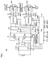
- Fig. 1 is a schematic block diagram of a hybrid vehicle according to a first embodiment of the invention.
- a hybrid vehicle 100 includes wheels 2, a power split device 3, an engine 4 and motor generators MG1 and MG2.
- Hybrid vehicle 100 also includes a power storage device B, a System Main Relay (which may also be referred to as an "SMR" hereinafter) 5, a booster converter 10, inverters 20 and 30, capacitors C1 and C2, power supply lines PL1 and PL2, a ground line SL, voltage sensors 72 and 74, and current sensors 76 and 78.
- Hybrid vehicle 100 further includes an abnormality sensing device 40, an AND gate 50 and an Electronic Control Unit (which may also be referred to as an "ECU” hereinafter) 60.
- ECU Electronic Control Unit
- Power split device 3 is coupled to engine 4 and motor generators MG1 and MG2 for distributing a power to them.
- power split device 3 may be formed of a planetary gear mechanism having a sun gear, a planetary carrier and a ring gear. Three rotation axes of them are connected to rotation axes of engine 4 and motor generators MG1 and MG2, respectively.
- motor generator MG1 has a hollow rotor, and a crankshaft of engine 4 extends through the rotor so that engine 4 and motor generators MG1 and MG2 can be mechanically connected to power split device 3.
- the rotation axis of motor generator MG2 is coupled to wheels 2 via a reduction gear and a differential gear (both not shown).
- a speed reducer for the rotation axis of motor generator MG2 may be additionally incorporated into power split device 3.
- Motor generator MG1 is incorporated into hybrid vehicle 100 as a device that operates as an electric power generator driven by engine 4 and also operates as an electric motor for starting engine 4.
- Motor generator MG2 is incorporated into hybrid vehicle 100 as an electric motor for driving the drive wheels, i.e., wheels 2.
- Power storage device B is a chargeable and dischargeable DC power supply, and is formed of a secondary battery such as nickel hydrogen battery or a lithium ion battery, for example. Power storage device B supplies a DC power to a power supply line PL1 via SMR 5. Power storage device B is charged with a DC power provided from booster converter 10 via power supply line PL1. Power storage device B may be formed of a capacitor having a large capacitance.
- SMR 5 includes relays RY1 and RY2.
- Relay RY1 is connected between a positive terminal of power storage device B and power supply line PL1.
- Relay RY2 is connected between a negative terminal of power storage device B and ground line SL.
- a signal SE from ECU 60 becomes active, relays RY1 and RY2 connect power storage device B to power supply line PL1 and ground line SL, respectively.
- Capacitor C1 smoothes variations of a voltage between power supply line PL1 and ground line SL.
- Voltage sensor 72 senses a voltage VL across the opposite terminals of capacitor C1, and provides sensed voltage VL to ECU 60.
- Booster converter 10 includes npn transistors Q1 and Q2, diodes D1 and D2, and a reactor L.
- Npn transistors Q1 and Q2 are connected in series between power supply line PL2 and ground line SL.
- Diodes D1 and D2 are connected in antiparallel to npn transistors Q1 and Q2, respectively.
- Reactor L is connected between power supply line PL1 and a node between npn transistors Q1 and Q2.
- Booster converter 10 boosts the voltage on power supply line PL1 based on a signal PWC provided from ECU 60, and provides it onto power supply line PL2. More specifically, booster converter 10 accumulates, as a magnetic field energy in reactor L, the current that flows when npn transistor Q2 is on, and discharges the accumulated energy to power supply line PL2 via a diode D1 when npn transistor Q2 is off so that booster converter 10 boosts the voltage on power supply line PL1.
- npn transistor Q2 As an on-duty of npn transistor Q2 increases, the power accumulation in reactor L can increase so that a higher voltage can be output. As the on-duty of npn transistor Q1 increases, the voltage on power supply line PL2 lowers. Therefore, by controlling the duty ratio of npn transistors Q1 and Q2, the voltage on power supply line PL2 can be controlled to be equal to or higher than the voltage on power supply line PL1.
- Capacitor C2 smoothes variations of the voltage placed between power supply line PL2 and ground line SL.
- Voltage sensor 74 senses a voltage VH across the opposite terminals of capacitor C2, and provides sensed voltage VH to ECU 60.
- Inverters 20 and 30 are arranged corresponding to motor generators MG1 and MG2, respectively.
- Inverter 20 drives motor generator MG1 in a power running mode or a regenerative mode according to a signal PWM1 from ECU 60.
- Inverter 20 is shut down when a shutdown signal DWN received from AND gate 50 becomes active.
- Inverter 30 drives motor generator MG2 in the power running mode or the regenerative mode according to a signal PWM2 from ECU 60. Inverter 30 is shut down when shutdown signal DWN received from AND gate 50 becomes active.
- Current sensor 76 senses a motor current MCRT1 flowing through motor generator MG1, and provides sensed motor current MCRT1 to ECU 60.
- Current sensor 78 senses a motor current MCRT2 flowing through motor generator MG2, and provides sensed motor current MCRT2 to ECU 60.
- Abnormality sensing device 40 receives voltage VL from voltage sensor 72. When voltage VL exceeds a threshold that is preset for protecting capacitor C1 from overvoltage breakdown, abnormality sensing device 40 activates a signal OVL and provides it to AND gate 50. When abnormality sensing device 40 senses an abnormality in itself, abnormality sensing device 40 activates signal OVL, and provides it to AND gate 50.
- AND gate 50 performs logical AND between signal OVL from abnormality sensing device 40 and a shutdown permission signal RG from ECU 60, and provides a result of the logical AND, as shutdown signal DWN, to inverters 20 and 30 as well as ECU 60.
- ECU 60 receives voltages VL and VH from respective voltage sensors 72 and 74, and receives motor currents MCRT1 and MCRT2 from respective current sensors 76 and 78. ECU 60 receives torque control values TR1 and TR2 as well as motor revolution speeds MRN1 and MRN2 from an external ECU (not shown).
- ECU 60 Based on these signals, ECU 60 produces signals PWC, PWM1 and PWM2 for driving booster converter 10 and motor generators MG1 and MG2, respectively, and provides these produced signals PWC, PWM1 and PWC2 to booster converter 10 and inverters 20 and 30, respectively.
- ECU 60 receives shutdown signal DWN from AND gate 50, and receives a limp-home run permission signal BLS from the external ECU. Based on these signals, ECU 60 produces shutdown permission signal RG for permitting the shutdown of inverters 20 and 30 in a manner to be described later, and provides shutdown permission signal RG thus produced to AND gate 50.
- ECU 60 activates signal SE to be provided to SMR 5.
- ECU 60 inactivates signal SE.
- Fig. 2 is a functional block diagram of ECU 60 shown in Fig. 1 .
- ECU 60 includes a converter control unit 61, first and second inverter control units 62 and 63, and a shutdown control unit 64.
- Converter control unit 61 arithmetically obtains a voltage command of power supply line PL2 based on torque control values TR1 and TR2 as well as motor revolution speeds MRN1 and MRN2, and arithmetically obtains a feedback voltage command based on voltages VL and VH.
- Converter control unit 61 arithmetically obtains duty ratios of npn transistors Q1 and Q2 based on the feedback voltage command, produces a PWM (Pulse Width Modulation) signal for turning on/off npn transistors Q1 and Q2, and provides it as signal PWC to booster converter 10.
- PWM Pulse Width Modulation
- First inverter control unit 62 produces a PWM signal for driving inverter 20 based on torque control value TR1, voltage VH and motor current MCRT1, and provides the produced PMW signal as signal PWM1 to inverter 20.
- Second inverter control unit 63 produces a PWM signal for driving inverter 30 based on torque control value TR2, voltage VH and motor current MCRT2, and provides the produced PWM signal as signal PWM2 to inverter 30.
- Shutdown control unit 64 activates shutdown permission signal RG when shutdown signal DWN is inactive, and provides it to AND gate 50. More specifically, since shutdown signal DWN is a logical AND between signal OVL provided from abnormality sensing device 40 and shutdown permission signal RG, shutdown control unit 64 activates shutdown permission signal RG when abnormality sensing device 40 does not sense an abnormality.
- AND gate 50 immediately activates shutdown signal DWN in response to the activation of signal OVL provided from abnormality sensing device 40. Therefore, inverters 20 and 30 are immediately shut down in response to the activation of signal OVL.
- shutdown control unit 64 In the state where shutdown signal DWN is active, and thus abnormality sensing device 40 senses an abnormality, shutdown control unit 64 inactivates shutdown permission signal RG to be output to AND gate 50, when limp-home run permission signal BLS received from the external ECU becomes active.
- Limp-home run permission signal BLS becomes active when it is possible to perform limp-home run (batteryless run) in which the electric power from power storage device B is not used, and the run is performed by driving motor generator MG2 with the electric power generated by motor generator MG1, or to perform the limp-home run (battery run) in which motor generator MG2 is driven with the electric power supplied from power storage device B.
- Limp-home run permission signal BLS may be produced from determination by the external ECU whether the limp-home run is possible in the current state.
- a button for instructing the limp-home run may be employed for activating the signal when a driver operates the button.
- Fig. 3 is a flowchart illustrating a control structure of shutdown control unit 64 shown in Fig. 2 . Processing in this flowchart is called from a main routine for execution at predetermined intervals or every time a predetermined condition is satisfied.
- shutdown control unit 64 determines whether shutdown signal DWN received from AND gate 50 is at an H-level (logical high level) or not (step S10). When shutdown control unit 64 determines that shutdown signal DWN is not at the H-level, i.e., that shutdown signal DWN is at an L-level (logical low level) (NO in step S10), shutdown control unit 64 provides shutdown permission signal RG at the H-level to AND gate 50 (step S20).
- shutdown control unit 64 determines in step S10 that shutdown signal DWN is at the H-level (YES in step S10), it determines based on limp-home run permission signal BLS whether the limp-home run is permitted or not (step S30). When shutdown control unit 64 determines that the limp-home run is permitted (YES in step S30), it provides shutdown permission signal RG at the L-level to AND gate 50 (step S40). Conversely, when the limp-home run is not permitted (NO in step S30), shutdown control unit 64 forwards the processing to step S20.
- ECU 60 produces signal PWC based on voltages VL and VH, torque control values TR1 and TR2, and motor revolution speeds MRN1 and MRN2, and provides signal PWC thus produced to booster converter 10.
- booster converter 10 boosts the voltage provided from power storage device B, and supplies it to inverters 20 and 30.
- ECU 60 produces signal PWM1 based on voltage VH, torque control value TR1 and motor current MCRT1, and provides signal PWM1 thus produced to inverter 20. Further, ECU 60 produces signal PWM2 based on voltage VH, torque control value TR2 and motor current MCRT2, and provides signal PWM2 thus produced to inverter 30.
- inverter 20 converts the DC voltage supplied from booster converter 10 into a three-phase AC voltage to drive motor generator MG1.
- Inverter 30 converts the DC voltage supplied from booster converter 10 into a three-phase AC voltage to drive motor generator MG2.
- motor generator MG1 generates a torque indicated by torque control value TR1
- motor generator MG2 generates a torque indicated by torque control value TR2
- Motor generator MG1 is coupled to engine 4 via power split device 3, and motor generator MG2 is coupled to wheels 2 via power split device 3.
- Motor generator MG1 starts engine 4, or generates an electric power, using the power provided from engine 4.
- Motor generator MG2 drives wheels 2, or generates an electric power during regenerative braking of the vehicle. Therefore, motor generator MG1 is primarily driven in the regenerative mode in which it generates the electric power, using the power supplied from engine 4.
- Motor generator MG2 is primarily driven in the power running mode in which the power for driving wheels 2 is generated.
- Power storage device B functions as a buffer for storing a surplus electric power when the electric power generated by motor generator MG1 is larger than the power consumed by motor generator MG2, and for covering a shortage of the electric power when the power consumed by motor generator MG2 is larger than the power generated by motor generator MG1.
- abnormality sensing device 40 senses the overvoltage based on voltage VL to activate signal OVL will now be discussed.
- Voltage VL becomes the overvoltage, e.g., in such a situation that on-failure (not allowing turn-off) occurs in npn transistor Q1 forming an upper arm of booster converter 10 and the voltage on power supply line PL2 is supplied to power supply line PL1 without being stepped down by booster converter 10.
- shutdown signal DWN from AND gate 50 Before signal OVL becomes active, shutdown signal DWN from AND gate 50 is inactive so that shutdown permission signal RG to be provided to AND gate 50 is kept active by ECU 60.
- abnormality sensing device 40 senses an abnormality to activate signal OVL
- AND gate 50 immediately activates shutdown signal DWN in response to the activation of signal OVL because shutdown permission signal RG from ECU 60 is active. Therefore, inverters 20 and 30 are immediately shut down in response to the activation of signal OVL.
- inverters 20 and 30 are immediately shut down when abnormality sensing device 40 senses the overvoltage based on voltage VL. Thereby, motor generators MG1 and MG2 immediately stop, and motor generator MG1 (or MG2) stops the power supply to power supply line PL2. Thereafter, the voltages on power supply lines PL2 and PL1 lower because a discharge resistor or auxiliary machinery (not shown) connected to power supply line PL1 consume the electric power.
- inverters 20 and 30 When inverters 20 and 30 are shut down in response to activation of signal OVL and motor generators MG1 and MG2 stop, it becomes impossible in this state to implement the limp-home run by motor generators MG1 and MG2. Therefore, when limp-home run permission signal BLS becomes active, ECU 60 inactivates shutdown permission signal RG provided to AND gate 50. Thereby, AND gate 50 inactivates shutdown signal DWN to release inverters 20 and 30 from the shutdown state. Thereby, inverters 20 and 30 become active to allow the limp-home run using motor generators MG1 and MG2.
- ECU 60 activates and outputs shutdown permission signal RG before abnormality sensing device 40 senses the overvoltage of voltage VL.
- abnormality sensing device 40 senses the overvoltage and activates signal OVL
- AND gate 50 immediately activates shutdown signal DWN and provides it to inverters 20 and 30.
- capacitor C1 can be protected from the overvoltage breakdown.
- the margin of capacitor C1 can be small so that capacitor C1 can be small in size.
- the auxiliary machinery (not shown) connected to power supply line PL1 can be protected from the overvoltage breakdown.
- the first embodiment when limp-home run permission signal BLS becomes active after inverters 20 and 30 are shut down according to shutdown signal DWN, ECU 60 inactivates shutdown permission signal RG. Thereby, even in the state where the abnormality sensed by abnormality sensing device 40 is present, inverters 20 and 30 can operate. Therefore, the first embodiment allows the limp-home run by motor generators MG1 and MG2 even when the abnormality sensed by abnormality sensing device 40 is present.
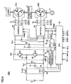
- Fig. 4 is a schematic block diagram of a hybrid vehicle according to a second embodiment of the invention.
- a hybrid vehicle 100A includes a booster converter 10A instead of booster converter 10 in the structure of hybrid vehicle 100 according to the first embodiment shown in Fig. 1 .
- Booster converter 10A differs from booster converter 10 in the first embodiment shown in Fig. 1 in that booster converter 10A receives signal OVL from abnormality sensing device 40. Booster converter 10A is shut down when signal OVL received from abnormality sensing device 40 becomes active.
- booster converter 10A The other structures and functions of booster converter 10A are the same as those of booster converter 10 in the first embodiment.
- the other structures of hybrid vehicle 100A are the same as those of hybrid vehicle 100 of the first embodiment.
- abnormality sensing device 40 senses the overvoltage based on voltage VL and activates signal OVL in hybrid vehicle 100A.
- Voltage VL becomes the overvoltage, e.g., in such a situation that a wire in SMR 5 breaks when inverters 20 and 30 are supplying a surplus electric power to power storage device B via booster converter 10.
- abnormality sensing device 40 senses the overvoltage based on voltage VL
- inverters 20 and 30 are immediately shut down, and the rising of voltage VH is avoided.
- inverters 20 and 30 are shut down. Thereby, the limp-home run is implemented after the stop of motor generators MG1 and MG2 in the substantially same manner as that in the first embodiment.
- capacitors C1 and C2 can be protected from the overvoltage, breakdown. Further, the margins of capacitors C1 and C2 can be small so that the sizes of capacitors C1 and C2 can be small.
- ECU 60 inactivates shutdown permission signal RG when limp-home run permission signal BLS becomes active after inverters 20 and 30 are shut down in response to shutdown signal DWN whereby, even when the abnormality sensed by abnormality sensing device 40 is present, inverters 20 and 30 can operate Therefore, the second embodiment allows the limp-home run using motor generators MG1 and MG2 even when the abnormality sensed by abnormality sensing device 40 is present.
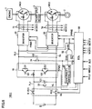
- Fig. 5 is a schematic block diagram of a hybrid vehicle according to a third embodiment of the invention.
- a hybrid vehicle 100B differs from the structure of hybrid vehicle 100 in the first embodiment of the invention shown in Fig. 1 in that booster converter 10, capacitor C1 and voltage sensor 72 are not employed.
- Replay RY1 of SMR 5 is connected between the positive terminal of power storage device B and power supply line PL2.
- hybrid vehicle 100B includes an abnormality sensing device 82, an AND gate 52 and an ECU 60A instead of abnormality sensing device 40, AND gate 50 and ECU 60 shown in Fig. 1 , respectively.
- Abnormality sensing device 82 receives voltage VH from voltage sensor 74. When voltage VH exceeds a threshold that is preset for protecting capacitor C2 from overvoltage breakdown, abnormality sensing device 82 activates a signal OVH and provides it to AND gate 52. When abnormality sensing device 82 senses an abnormality in itself, abnormality sensing device 82 likewise activates signal OVH and provides it to AND gate 52.
- abnormality sensing device 82 may sense the overvoltage of voltage VH, and it can be considered that this situation, i.e., the sensing of the overvoltage occurs when the break occurs in SMR 5 while inverters 20 and 30 is supplying a surplus power to power storage device B via SMR 5.
- AND gate 52 performs logical AND between signal OVH from abnormality sensing device 82 and shutdown permission signal RG from ECU 60A, and provides a result of the logical AND as shutdown signal DWN to inverters 20 and 30 as well as ECU 60A.
- ECU 60A The function of ECU 60A is the same as that of ECU 60 shown in Fig. 1 except for that it does not produce signal PWC for driving booster converter 10.
- the structure of ECU 60A is the same as that of ECU 60 shown in Fig. 2 except for that converter control unit 61 is not employed.
- hybrid vehicle 100B The other structures of hybrid vehicle 100B are the same as those of hybrid vehicle 100 shown in Fig. 1 .
- shutdown signal DWN from AND gate 52 is inactive so that shutdown permission signal RG provided to AND gate 52 is kept active by ECU 60A.
- abnormality sensing device 82 senses the abnormality and activates signal OVH
- AND gate 52 immediately activates shutdown signal DWN in response to the activation of signal OVH because shutdown permission signal RG from ECU 60A is active. Therefore, inverters 20 and 30 are immediately shut down in response to the activation of signal OVH.
- abnormality sensing device 82 senses the overvoltage based on voltage VH, inverters 20 and 30 are immediately shut down. Thereby, motor generators MG1 and MG2 immediately stop, and motor generator MG1 (or MG2) no longer supplies the electric power to power supply line PL2. Thereafter, the discharge resistor, auxiliary machinery and the like (not shown) consume the electric power so that the voltage on power supply line PL2 lowers.
- ECU 60A activates and outputs shutdown permission signal RG before abnormality sensing device 82 senses the overvoltage of voltage VH.
- abnormality sensing device 82 senses the overvoltage and activates signal OVH
- AND gate 52 immediately activates shutdown signal DWN to provide it to inverters 20 and 30.
- capacitor C2 can be protected from the overvoltage breakdown.
- the margin of capacitor C2 can be small so that sizes of capacitor C2 can be small.
- the auxiliary machinery (not shown) connected to power supply line PL2 can be protected from the overvoltage breakdown,
- ECU 60A inactivates shutdown permission signal RG when limp-home run permission signal BLS becomes active after inverters 20 and 30 are shut down in response to shutdown signal DWN.
- inverters 20 and 30 can operate. Therefore, the third embodiment allows the limp-home run using motor generators MG1 and MG2 even when the abnormality sensed by abnormality sensing device 82 is present.
- Fig. 6 is a schematic block diagram of a hybrid vehicle according to a fourth embodiment of the invention.
- a structure of a hybrid vehicle 100C differs from that of hybrid vehicle 100 of the first embodiment shown in Fig. 1 in that abnormality sensing device 82 and AND gate 52 are employed instead of abnormality sensing device 40 and AND gate 50
- Abnormality sensing device 82 and AND gate 52 are already described in connection with the third embodiment, and therefore description thereof is not repeated.
- Abnormality sensing device 82 senses the overvoltage of voltage VH, e.g., in such a situation that the off-failure (not allowing turn-on) occurs in npn transistor Q1 forming the upper arm of booster converter 10 so that the current cannot flow from power supply line PL2 to power supply line PL1.
- shutdown signal DWN from AND gate 52 is inactive similarly to the third embodiment so that ECU 60 has already activated shutdown permission signal RG provided to AND gate 52. Therefore, when signal OVH becomes active, shutdown signal DWN immediately becomes active in response to it, and inverters 20 and 30 are immediately shut down. Thereby, motor generators MG1 and MG2 immediately stop, and motor generator MG1 (or MG2) no longer supplies the electric power to power supply line PL2. As a result, the rising of voltage VH is suppressed, and capacitor C2 is protected from the overvoltage breakdown.
- the fourth embodiment can achieve substantially the same effect as the third embodiment.
- the above structure may be configured such that booster converter 10 is shut down when signal OVH from abnormality sensing device 82 becomes active, similarly to the second embodiment.
- This configuration suppresses the rising of voltage VL, and can also protect capacitor C1 from the overvoltage breakdown.
- a fifth embodiment performs the abnormality sensing based on both voltage VL on the low voltage side of booster converter 10 and voltage VH on the high voltage side.
- Fig. 7 is a schematic block diagram of a hybrid vehicle according to the fifth embodiment of the invention.
- a hybrid vehicle 100D has the same structure as hybrid vehicle 100 of the first embodiment shown in Fig. 1 except for that hybrid vehicle 100D further includes abnormality sensing device 82, and includes an OR gate 84 and an AND gate 86 instead of AND gate 50.
- OR gate 84 performs logical OR between signal OVL from abnormality sensing device 40 and signal OVH from abnormality sensing device 82, and provides a result of the local OR to AND gate 86.
- AND gate 86 performs logical AND between an output of OR gate 84 and shutdown permission signal RG from ECU 60, and provides a result of the logical AND as shutdown signal DWN to inverters 20 and 30 as well as ECU 60.
- Abnormality sensing device 82 is already described in connection with the third embodiment, and therefore description thereof is not repeated.
- the other structures of hybrid vehicle 100D are the same as those of hybrid vehicle 100 of the first embodiment
- shutdown signal DWN provided from AND gate 86 is inactive so that ECU 60 has already activated shutdown permission signal RG provided to AND gate 86. Therefore, when one of signals OVL and OVH becomes active, shutdown signal DWN immediately becomes active in response to such activation, and inverters 20 and 30 are immediately shut down. Thereby, motor generators MG1 and MG2 immediately stop, and the power supply from motor generator MG1 (or MG2) to power supply line PL2 stops. Consequently, the rising of voltage VH is suppressed, and capacitor C2 is protected from the overvoltage breakdown.
- the fifth embodiment can protect capacitors C1 and C2 from the overvoltage breakdown.
- the margins of capacitors C1 and C2 can be small. Consequently, the sizes of capacitors C1 and C2 can be small. Further, even when the abnormality sensed by abnormality sensing device 40 or 82 is present, the limp-home run using motor generators MG1 and MG2 can be performed.
- the fifth embodiment may be configured such that booster converter 10 is shut down when signal OVL from abnormality sensing device 40 or signal OVH from abnormality sensing device 82 becomes active, similarly to the second embodiment.
Description
- The invention relates to an electric motor drive apparatus driving an electric motor mounted on a hybrid vehicle, a hybrid vehicle equipped with the electric motor drive apparatus and a stop control method of an electric power converting device.
- In recent years, large attention has been given to a hybrid vehicle equipped, as drive power sources, with a battery, inverters and motors driven by the inverters in addition to a conventional engine.
-
Japanese Patent Laying-Open No. 10-191503 - In this hybrid vehicle, even when the battery that can function as an electric power buffer is isolated, the power generation output of the power generator follows the load so that a smoothing capacitor can be protected from overvoltage breakdown.
- However, when the battery is suddenly isolated due to a break in a wire of the system main relay, or when a booster device malfunctions in a system having the booster device between the battery and the inverter, an unexpected overvoltage may rapidly occur due to the power supplied from the power generator. In view of this situation, therefore, even the foregoing hybrid vehicle must keep a capacitance margin of the smoothing capacitor to a certain extent, and this increases sizes of the capacitor.
- JPH1042590 relates to a voltage-type inverter.
- Aspects of the invention are set out in the claims.
- Accordingly, the invention has been made for overcoming the above problem, and an object of the invention is provide an electric motor drive apparatus that can reduce a margin of a smoothing capacitor.
- Another object of the invention is to provide a hybrid vehicle provided with an electric motor drive apparatus that can reduce a margin of a smoothing capacitor.
- Still another object of the invention is to provide a stop control method of an electric power converting device that can reduce a margin of a smoothing capacitor.
- According to the invention, an electric motor drive apparatus includes a capacitance element smoothing a DC voltage; an electric power converting device performing electric power conversion between the capacitance element and at least one electric motor; an abnormality sensing device sensing an abnormality relating to the capacitance element, and providing a signal being activated when the abnormality is sensed; a control device activating and providing a shutdown permission signal for permitting shutdown of the electric power converting device at least before the abnormality sensing device senses the abnormality; and a shutdown circuit activating a shutdown signal instructing shutdown of the electric power converting device and providing the shutdown signal to the electric power converting device when the signal provided from the abnormality sensing device becomes active while the shutdown permission signal is active.
- First to fifth embodiments that will be described later correspond to this invention. More specifically, a capacitor C1 in the first, second and fifth embodiments as well as a capacitor C2 in third, fourth and fifth embodiments correspond to the foregoing "capacitance element". A
booster converter 10 andinverters booster converter 10A andinverters inverters - Preferably, the electric motor drive apparatus further includes a DC power supply; and a booster device boosting a voltage provided from the DC power supply and providing the boosted voltage to the capacitance element. The electric power converting device includes a drive device converting the voltage provided from the capacitance element and driving the at least one electric motor.
- The fourth embodiment that will be described later corresponds to this invention. More specifically, in the fourth embodiment, capacitor C2 corresponds to the foregoing "capacitance element", and
inverters - Further preferably, the electric motor drive apparatus further includes a DC power supply providing a voltage to the capacitance element. The electric power converting device includes a booster device boosting a voltage provided from the capacitance element, and a drive device converting the voltage boosted by the booster device and driving the at least one electric motor. The shutdown circuit activates the shutdown signal and provides the shutdown signal to the drive device when the signal provided from the abnormality sensing device becomes active while the shutdown permission signal is active.
- The first and second embodiments that will be described later correspond to this invention. More specifically, in the first and second embodiments, capacitor C1 corresponds to the foregoing "capacitance element". Booster
converter 10 andinverters booster converter 10A andinverters Booster converters inverters - Preferably, the electric motor drive apparatus includes a DC power supply; one additional capacitance element smoothing the voltage supplied from the DC power supply; and a booster device boosting a voltage supplied from the one additional capacitance element and providing the boosted voltage to the capacitance element. The electric power converting device includes a drive device converting the voltage supplied from the capacitance element and driving the at least one electric motor. The abnormality sensing device further senses an abnormality relating to the one additional capacitance element, and activates the signal when the abnormality is sensed in at least one of the capacitance element and the one additional capacitance element.
- The fifth embodiment that will be described later corresponds to this invention. More specifically, in the fifth embodiment, capacitor C2 corresponds to the foregoing "capacitance element", and capacitor C1 corresponds to the foregoing "one additional capacitance element".
Booster converter 10 corresponds to the foregoing "booster device", andinverters devices - Preferably, the booster device is shut down when the signal from the abnormality sensing device becomes active.
- Preferably, the control device inactivates the shutdown permission signal when a predetermined condition is satisfied after the drive device of the electric power converting device is shut down according to the shutdown signal.
- Further preferably, the drive device can drive first and second electric motors corresponding to the at least one electric motor in a regenerative mode and a power running mode, respectively The predetermined condition is satisfied when a limp-home operation of driving the second electric motor using an electric power generated by the first electric motor without using an electric power supplied from the DC power supply is allowed.
- Further preferably, the drive device can drive first and second electric motors corresponding to the at least one electric motor in a regenerative mode and a power running mode, respectively. The predetermined condition is satisfied when a limp-home operation of driving the second electric motor using an electric power supplied from the DC power supply is allowed.
- Further preferably, the first electric motor is coupled to an internal combustion engine. When the abnormality sensed by the abnormality sensing device is not present, the internal combustion engine generates at least one of a drive power for generating the electric power by the first electric motor and a drive power for a vehicle, and the second electric motor generates the vehicle drive power, using the electric power supplied from at least one of the DC power supply and the first electric motor.
- Preferably, the abnormality sensing device activates the signal when a voltage across opposite terminals of the capacitance element or the one additional capacitance element exceeds a predetermined threshold.
- Further preferably, when the abnormality sensing device senses an abnormality in the device itself, the abnormality sensing device activates the signal.
- Further, according to the invention, an electric motor drive apparatus includes a DC power supply; a capacitance element smoothing a voltage supplied from the DC power supply; a booster device boosting a voltage supplied from the capacitance element; first and second drive devices driving first and second electric motors based on the voltage boosted by the booster device, respectively; a voltage sensing device sensing a voltage across opposite terminals of the capacitance element; an abnormality sensing device providing a signal to be activated when the voltage sensed by the voltage sensing device exceeds a predetermined threshold; a control device activating and providing a shutdown permission signal for permitting shutdown of the first and second drive devices at least before the abnormality sensing device senses the abnormality; and a shutdown circuit activating a shutdown signal instructing shutdown of the first and second drive devices and providing the shutdown signal to the first and second drive devices when the signal provided from the abnormality sensing device becomes active while the shutdown permission signal is active.
- The first embodiment that will be described later corresponds to this invention. More specifically, in the first embodiment, capacitor C1 corresponds to the foregoing "capacitance element".
Booster converter 10 corresponds to the foregoing "booster device".Inverters voltage sensor 72 corresponds to the foregoing "voltage sensing device". Further,abnormality sensing device 40 corresponds to the foregoing "abnormality sensing device", and anECU 60 corresponds to the foregoing "control device". Further, anAND gate 50 corresponds to the foregoing "shutdown circuit". - According to the invention, a hybrid vehicle includes an internal combustion engine; a first motor generator generating an electric power using a motive power supplied from the internal combustion engine; a second motor generator generating a driving power of the vehicle; and the electric motor drive apparatus according to one of
claims 2 to 4. The drive device included in the electric motor drive apparatus includes first and second inverters driving the first and second motor generators, respectively. - In each of the embodiments that will be described later, an
engine 4 corresponds to the foregoing "internal combustion engine". A motor generator MG1 corresponds to the foregoing "first motor generator", and a motor generator MG2 corresponds to the foregoing "second motor generator". Further, aninverter 20 corresponds to the foregoing "first inverter", and aninverter 30 corresponds to the foregoing "second inverter". - Preferably, after the first and second inverters are shutdown according to the shutdown signal provided from the shutdown circuit included in the electric power drive apparatus, the control device included in the electric motor drive apparatus inactivates the shutdown permission signal when the control device determines that a limp-home run (batteryless run) performed by driving the second motor generator using the electric power generated by the first motor generator without using an electric power supplied from the DC power supply is allowed.
- Preferably, after the first and second inverters are shutdown according to the shutdown signal provided from the shutdown circuit included in the electric power drive apparatus, the control device included in the electric motor drive apparatus inactivates the shutdown permission signal when the control device determines that a limp-home run (batteryless run) performed by driving the second motor generator using an electric power supplied from the DC power supply is allowed.
- Further preferably, when the abnormality sensed by the abnormality sensing device included in the electric motor drive apparatus is not present, the internal combustion engine generates at least one of a drive power for generating the electric power by the first motor generator and a drive power for the vehicle, and the second motor generator generates the vehicle drive power, using the electric power supplied from at least one of the DC power supply and the first motor generator.
- According to the invention, a stop control method of stopping an electric power converting device performing electric power conversion between a capacitance element smoothing a DC voltage and at least one electric motor, includes a first step of sensing an abnormality relating to the capacitance element; a second step of activating a shutdown permission signal for permitting shutdown of the electric power converting device before the abnormality is sensed; and a third step of shutting down the electric power converting device when the abnormality is sensed while the shutdown permission signal is active.
- Preferably, the stop control method of the electric powers converting device includes a fourth step of determining whether a predetermined limp-home operation is allowed or not when the electric power converting device is in a shutdown state; and a fifth step of inactivating the shutdown permission signal when it is determined in the fourth step that the predetermined limp-home operation can be performed.
- In this invention, the control device activates and provides the shutdown permission signal at least before the abnormality sensing device senses the abnormality. Therefore, when the signal from the abnormality sensing device becomes active, the shutdown circuit immediately activates the shutdown signal and provides it to the drive device. It can be considered that the abnormality sensing device senses the abnormality, e.g., in such cases that, due to a failure in the booster device, a current cannot flow from a high voltage side of the booster device to a low voltage side thereof or a voltage is supplied from the high voltage side of the booster device to the low voltage side thereof without being stepped down. In these cases, according to the invention, the drive device is immediately shut down in response to the sensing of the abnormality by the abnormality sensing device. Therefore, when the electric motor is being driven in the regenerative mode, the power supply from the electric motor immediately stops. Thereafter, a discharge resistor or the like performs discharge so that a voltage on a high voltage side of the booster device lowers.
- Therefore, the invention can protect the capacitance element and the one additional capacitance element from overvoltage breakdown, and further can reduce margins of these capacitance elements. Consequently, sizes of these capacitance elements can be small. Further, other devices arranged on the low voltage side of the booster device are protected from the overvoltage breakdown.
- Since the booster device is shut down when the signal from the abnormality sensing device becomes active, the invention can avoid the rising of the voltage across the opposite terminals of the capacitance element arranged on the low voltage side of the booster device. When the booster device is shut down while the electric motor is being driven in the regenerative mode, the voltage across the opposite terminals of the capacitance element arranged between the booster device and the electric motor may rise. In this case, when the abnormality sensing device senses the abnormality, the drive device is immediately shut down so that the invention can avoid the rising of the voltage across the opposite terminals of the capacitance element arranged between the booster device and the electric motor.
- Accordingly, the invention can protect the capacitance element arranged between the booster device and the electric motor from the overvoltage breakdown, and further can reduce the margin of the capacitance element. Consequently, the sizes of the capacitance element can be small.
- According to the invention, when the predetermined condition is satisfied after the drive device is shut down according to the shutdown signal, the control device inactivates the shutdown permission signal. Therefore, the drive device can operate even in the state where the abnormality sensed by the abnormality sensing device is present.
- According to the invention, therefore, the electric motor can perform the limp-home operation even when the abnormality sensed by the abnormality sensing device is present.
- In the invention, when the control device determines that the batteryless run by the first and second motor generators or the motor run by the second motor generator can be performed after shut-down of the first and second inverters according to the shutdown signal, the control device inactivates the shutdown permission signal. Therefore, even when the abnormality sensed by the abnormality sensing device is present, the first and second inverters can operate.
- According to the invention, therefore, even when the abnormality sensed by the abnormality sensing device is present, it is possible to perform the batteryless run by the first and second motor generators as well as the motor run by the second motor generator.
-
-
Fig. 1 is a schematic block diagram of a hybrid vehicle according to a first embodiment of the invention. -
Fig. 2 is a functional block diagram of an ECU shown inFig. 1 . -
Fig. 3 is a flowchart illustrating a control structure of a shutdown control unit shown inFig. 2 . -
Fig. 4 is a schematic block diagram of a hybrid vehicle according to a second embodiment of the invention -
Fig. 5 is a schematic block diagram of a hybrid vehicle of a third embodiment of the invention. -
Fig. 6 is a schematic block diagram of a hybrid vehicle of a fourth embodiment of the invention. -
Fig. 7 is a schematic block diagram of a hybrid vehicle of a fifth embodiment of the invention. - Embodiments of the invention will now be described with reference to the drawings. The same or corresponding portions bear the same reference numbers, and description thereof is not repeated.
-
Fig. 1 is a schematic block diagram of a hybrid vehicle according to a first embodiment of the invention. Referring toFig. 1 , ahybrid vehicle 100 includeswheels 2, apower split device 3, anengine 4 and motor generators MG1 and MG2.Hybrid vehicle 100 also includes a power storage device B, a System Main Relay (which may also be referred to as an "SMR" hereinafter) 5, abooster converter 10,inverters voltage sensors current sensors Hybrid vehicle 100 further includes anabnormality sensing device 40, an ANDgate 50 and an Electronic Control Unit (which may also be referred to as an "ECU" hereinafter) 60. - Power split
device 3 is coupled toengine 4 and motor generators MG1 and MG2 for distributing a power to them. For example, power splitdevice 3 may be formed of a planetary gear mechanism having a sun gear, a planetary carrier and a ring gear. Three rotation axes of them are connected to rotation axes ofengine 4 and motor generators MG1 and MG2, respectively. For example, motor generator MG1 has a hollow rotor, and a crankshaft ofengine 4 extends through the rotor so thatengine 4 and motor generators MG1 and MG2 can be mechanically connected topower split device 3. - The rotation axis of motor generator MG2 is coupled to
wheels 2 via a reduction gear and a differential gear (both not shown). A speed reducer for the rotation axis of motor generator MG2 may be additionally incorporated intopower split device 3. - Motor generator MG1 is incorporated into
hybrid vehicle 100 as a device that operates as an electric power generator driven byengine 4 and also operates as an electric motor for startingengine 4. Motor generator MG2 is incorporated intohybrid vehicle 100 as an electric motor for driving the drive wheels, i.e.,wheels 2. - Power storage device B is a chargeable and dischargeable DC power supply, and is formed of a secondary battery such as nickel hydrogen battery or a lithium ion battery, for example. Power storage device B supplies a DC power to a power supply line PL1 via
SMR 5. Power storage device B is charged with a DC power provided frombooster converter 10 via power supply line PL1. Power storage device B may be formed of a capacitor having a large capacitance. -
SMR 5 includes relays RY1 and RY2. Relay RY1 is connected between a positive terminal of power storage device B and power supply line PL1. Relay RY2 is connected between a negative terminal of power storage device B and ground line SL. When a signal SE fromECU 60 becomes active, relays RY1 and RY2 connect power storage device B to power supply line PL1 and ground line SL, respectively. - Capacitor C1 smoothes variations of a voltage between power supply line PL1 and ground line SL.
Voltage sensor 72 senses a voltage VL across the opposite terminals of capacitor C1, and provides sensed voltage VL toECU 60. -
Booster converter 10 includes npn transistors Q1 and Q2, diodes D1 and D2, and a reactor L. Npn transistors Q1 and Q2 are connected in series between power supply line PL2 and ground line SL. Diodes D1 and D2 are connected in antiparallel to npn transistors Q1 and Q2, respectively. Reactor L is connected between power supply line PL1 and a node between npn transistors Q1 and Q2. -
Booster converter 10 boosts the voltage on power supply line PL1 based on a signal PWC provided fromECU 60, and provides it onto power supply line PL2. More specifically,booster converter 10 accumulates, as a magnetic field energy in reactor L, the current that flows when npn transistor Q2 is on, and discharges the accumulated energy to power supply line PL2 via a diode D1 when npn transistor Q2 is off so thatbooster converter 10 boosts the voltage on power supply line PL1. - As an on-duty of npn transistor Q2 increases, the power accumulation in reactor L can increase so that a higher voltage can be output. As the on-duty of npn transistor Q1 increases, the voltage on power supply line PL2 lowers. Therefore, by controlling the duty ratio of npn transistors Q1 and Q2, the voltage on power supply line PL2 can be controlled to be equal to or higher than the voltage on power supply line PL1.
- Capacitor C2 smoothes variations of the voltage placed between power supply line PL2 and ground line SL.
Voltage sensor 74 senses a voltage VH across the opposite terminals of capacitor C2, and provides sensed voltage VH toECU 60. -
Inverters Inverter 20 drives motor generator MG1 in a power running mode or a regenerative mode according to a signal PWM1 fromECU 60.Inverter 20 is shut down when a shutdown signal DWN received from ANDgate 50 becomes active. -
Inverter 30 drives motor generator MG2 in the power running mode or the regenerative mode according to a signal PWM2 fromECU 60.Inverter 30 is shut down when shutdown signal DWN received from ANDgate 50 becomes active. -
Current sensor 76 senses a motor current MCRT1 flowing through motor generator MG1, and provides sensed motor current MCRT1 toECU 60.Current sensor 78 senses a motor current MCRT2 flowing through motor generator MG2, and provides sensed motor current MCRT2 toECU 60. -
Abnormality sensing device 40 receives voltage VL fromvoltage sensor 72. When voltage VL exceeds a threshold that is preset for protecting capacitor C1 from overvoltage breakdown,abnormality sensing device 40 activates a signal OVL and provides it to ANDgate 50. Whenabnormality sensing device 40 senses an abnormality in itself,abnormality sensing device 40 activates signal OVL, and provides it to ANDgate 50. - AND
gate 50 performs logical AND between signal OVL fromabnormality sensing device 40 and a shutdown permission signal RG fromECU 60, and provides a result of the logical AND, as shutdown signal DWN, toinverters ECU 60. -
ECU 60 receives voltages VL and VH fromrespective voltage sensors current sensors ECU 60 receives torque control values TR1 and TR2 as well as motor revolution speeds MRN1 and MRN2 from an external ECU (not shown). - Based on these signals,
ECU 60 produces signals PWC, PWM1 and PWM2 for drivingbooster converter 10 and motor generators MG1 and MG2, respectively, and provides these produced signals PWC, PWM1 and PWC2 tobooster converter 10 andinverters - Further,
ECU 60 receives shutdown signal DWN from ANDgate 50, and receives a limp-home run permission signal BLS from the external ECU. Based on these signals,ECU 60 produces shutdown permission signal RG for permitting the shutdown ofinverters gate 50. - Further, when the vehicle system starts,
ECU 60 activates signal SE to be provided toSMR 5. When the vehicle system is shut down,ECU 60 inactivates signal SE. -
Fig. 2 is a functional block diagram ofECU 60 shown inFig. 1 . Referring toFig. 2 ,ECU 60 includes aconverter control unit 61, first and secondinverter control units shutdown control unit 64. -
Converter control unit 61 arithmetically obtains a voltage command of power supply line PL2 based on torque control values TR1 and TR2 as well as motor revolution speeds MRN1 and MRN2, and arithmetically obtains a feedback voltage command based on voltages VL and VH.Converter control unit 61 arithmetically obtains duty ratios of npn transistors Q1 and Q2 based on the feedback voltage command, produces a PWM (Pulse Width Modulation) signal for turning on/off npn transistors Q1 and Q2, and provides it as signal PWC tobooster converter 10. - First
inverter control unit 62 produces a PWM signal for drivinginverter 20 based on torque control value TR1, voltage VH and motor current MCRT1, and provides the produced PMW signal as signal PWM1 toinverter 20. - Second
inverter control unit 63 produces a PWM signal for drivinginverter 30 based on torque control value TR2, voltage VH and motor current MCRT2, and provides the produced PWM signal as signal PWM2 toinverter 30. -
Shutdown control unit 64 activates shutdown permission signal RG when shutdown signal DWN is inactive, and provides it to ANDgate 50. More specifically, since shutdown signal DWN is a logical AND between signal OVL provided fromabnormality sensing device 40 and shutdown permission signal RG,shutdown control unit 64 activates shutdown permission signal RG whenabnormality sensing device 40 does not sense an abnormality. - Thereby, AND
gate 50 immediately activates shutdown signal DWN in response to the activation of signal OVL provided fromabnormality sensing device 40. Therefore,inverters - In the state where shutdown signal DWN is active, and thus
abnormality sensing device 40 senses an abnormality,shutdown control unit 64 inactivates shutdown permission signal RG to be output to ANDgate 50, when limp-home run permission signal BLS received from the external ECU becomes active. - Limp-home run permission signal BLS becomes active when it is possible to perform limp-home run (batteryless run) in which the electric power from power storage device B is not used, and the run is performed by driving motor generator MG2 with the electric power generated by motor generator MG1, or to perform the limp-home run (battery run) in which motor generator MG2 is driven with the electric power supplied from power storage device B. Limp-home run permission signal BLS may be produced from determination by the external ECU whether the limp-home run is possible in the current state. A button for instructing the limp-home run may be employed for activating the signal when a driver operates the button.
- When shutdown permission signal RG becomes inactive, AND
gate 50 inactivates shutdown signal DWN so thatinverters -
Fig. 3 is a flowchart illustrating a control structure ofshutdown control unit 64 shown inFig. 2 . Processing in this flowchart is called from a main routine for execution at predetermined intervals or every time a predetermined condition is satisfied. - Referring to
Fig. 3 ,shutdown control unit 64 determines whether shutdown signal DWN received from ANDgate 50 is at an H-level (logical high level) or not (step S10). Whenshutdown control unit 64 determines that shutdown signal DWN is not at the H-level, i.e., that shutdown signal DWN is at an L-level (logical low level) (NO in step S10),shutdown control unit 64 provides shutdown permission signal RG at the H-level to AND gate 50 (step S20). - When
shutdown control unit 64 determines in step S10 that shutdown signal DWN is at the H-level (YES in step S10), it determines based on limp-home run permission signal BLS whether the limp-home run is permitted or not (step S30). Whenshutdown control unit 64 determines that the limp-home run is permitted (YES in step S30), it provides shutdown permission signal RG at the L-level to AND gate 50 (step S40). Conversely, when the limp-home run is not permitted (NO in step S30),shutdown control unit 64 forwards the processing to step S20. - Referring to
Fig. 1 again, the whole operation ofhybrid vehicle 100 will be described below.ECU 60 produces signal PWC based on voltages VL and VH, torque control values TR1 and TR2, and motor revolution speeds MRN1 and MRN2, and provides signal PWC thus produced tobooster converter 10. Thereby,booster converter 10 boosts the voltage provided from power storage device B, and supplies it toinverters -
ECU 60 produces signal PWM1 based on voltage VH, torque control value TR1 and motor current MCRT1, and provides signal PWM1 thus produced toinverter 20. Further,ECU 60 produces signal PWM2 based on voltage VH, torque control value TR2 and motor current MCRT2, and provides signal PWM2 thus produced toinverter 30. - Thereby,
inverter 20 converts the DC voltage supplied frombooster converter 10 into a three-phase AC voltage to drive motor generator MG1.Inverter 30 converts the DC voltage supplied frombooster converter 10 into a three-phase AC voltage to drive motor generator MG2. Thereby, motor generator MG1 generates a torque indicated by torque control value TR1, and motor generator MG2 generates a torque indicated by torque control value TR2 - Motor generator MG1 is coupled to
engine 4 viapower split device 3, and motor generator MG2 is coupled towheels 2 viapower split device 3. Motor generator MG1 startsengine 4, or generates an electric power, using the power provided fromengine 4. Motor generator MG2 driveswheels 2, or generates an electric power during regenerative braking of the vehicle. Therefore, motor generator MG1 is primarily driven in the regenerative mode in which it generates the electric power, using the power supplied fromengine 4. Motor generator MG2 is primarily driven in the power running mode in which the power for drivingwheels 2 is generated. - Power storage device B functions as a buffer for storing a surplus electric power when the electric power generated by motor generator MG1 is larger than the power consumed by motor generator MG2, and for covering a shortage of the electric power when the power consumed by motor generator MG2 is larger than the power generated by motor generator MG1.
- The case where
abnormality sensing device 40 senses the overvoltage based on voltage VL to activate signal OVL will now be discussed. Voltage VL becomes the overvoltage, e.g., in such a situation that on-failure (not allowing turn-off) occurs in npn transistor Q1 forming an upper arm ofbooster converter 10 and the voltage on power supply line PL2 is supplied to power supply line PL1 without being stepped down bybooster converter 10. - Before signal OVL becomes active, shutdown signal DWN from AND
gate 50 is inactive so that shutdown permission signal RG to be provided to ANDgate 50 is kept active byECU 60. Whenabnormality sensing device 40 senses an abnormality to activate signal OVL, ANDgate 50 immediately activates shutdown signal DWN in response to the activation of signal OVL because shutdown permission signal RG fromECU 60 is active. Therefore,inverters - Thus,
inverters abnormality sensing device 40 senses the overvoltage based on voltage VL. Thereby, motor generators MG1 and MG2 immediately stop, and motor generator MG1 (or MG2) stops the power supply to power supply line PL2. Thereafter, the voltages on power supply lines PL2 and PL1 lower because a discharge resistor or auxiliary machinery (not shown) connected to power supply line PL1 consume the electric power. - When
inverters ECU 60 inactivates shutdown permission signal RG provided to ANDgate 50. Thereby, ANDgate 50 inactivates shutdown signal DWN to releaseinverters inverters - According to the first embodiment, as described above,
ECU 60 activates and outputs shutdown permission signal RG beforeabnormality sensing device 40 senses the overvoltage of voltage VL. Thereby, whenabnormality sensing device 40 senses the overvoltage and activates signal OVL, ANDgate 50 immediately activates shutdown signal DWN and provides it to inverters 20 and 30. According to the first embodiment, therefore, even when the abnormality occurs and, for example, even when voltage VL across the opposite terminals of capacitor C1 may become the overvoltage due to the on-failure of the upper arm ofbooster converter 10, capacitor C1 can be protected from the overvoltage breakdown. The margin of capacitor C1 can be small so that capacitor C1 can be small in size. Further, the auxiliary machinery (not shown) connected to power supply line PL1 can be protected from the overvoltage breakdown. - In this first embodiment, when limp-home run permission signal BLS becomes active after
inverters ECU 60 inactivates shutdown permission signal RG. Thereby, even in the state where the abnormality sensed byabnormality sensing device 40 is present,inverters abnormality sensing device 40 is present. -
Fig. 4 is a schematic block diagram of a hybrid vehicle according to a second embodiment of the invention. Referring toFig. 4 , ahybrid vehicle 100A includes abooster converter 10A instead ofbooster converter 10 in the structure ofhybrid vehicle 100 according to the first embodiment shown inFig. 1 . -
Booster converter 10A differs frombooster converter 10 in the first embodiment shown inFig. 1 in thatbooster converter 10A receives signal OVL fromabnormality sensing device 40.Booster converter 10A is shut down when signal OVL received fromabnormality sensing device 40 becomes active. - The other structures and functions of
booster converter 10A are the same as those ofbooster converter 10 in the first embodiment. The other structures ofhybrid vehicle 100A are the same as those ofhybrid vehicle 100 of the first embodiment. - Description will be given on the case where
abnormality sensing device 40 senses the overvoltage based on voltage VL and activates signal OVL inhybrid vehicle 100A. Voltage VL becomes the overvoltage, e.g., in such a situation that a wire inSMR 5 breaks wheninverters booster converter 10. - When the break occurs in
SMR 5 to isolate power storage device B functioning as a buffer from power supply line PL1 and ground line SL, voltage VL rises, andabnormality sensing device 40 senses the abnormality. Thereby, signal OVL becomes active, andbooster converter 10A is shut down in response to the activation of signal OVL. Thereby, a current no longer flows from power supply line PL2 to power supply line PL1 so that the rising of voltage VL is suppressed. Consequently, capacitor C1 is protected from the overvoltage breakdown. - When the current does not flow from power supply line PL2 to power supply line PL1 due to shutdown of
booster convener 10A, voltage VH may rise. However, when signal OVL becomes active, ANDgate 50 activates shutdown signal down immediately in response to the activation of signal OVL because shutdown permission signal RG fromECU 60 is active. Thereby,inverters - More specifically, when
abnormality sensing device 40 senses the overvoltage based on voltage VL,inverters - In response to the activation of signal OVL,
inverters - According to the second embodiment, as described above, even when such an abnormality occurs that voltage VL across the opposite terminals of capacitor C1 as well as voltage VH across the opposite terminals of capacitor C2 may become overvoltages due to the break in
SMR 5, capacitors C1 and C2 can be protected from the overvoltage, breakdown. Further, the margins of capacitors C1 and C2 can be small so that the sizes of capacitors C1 and C2 can be small. - In the second embodiment,
ECU 60 inactivates shutdown permission signal RG when limp-home run permission signal BLS becomes active afterinverters abnormality sensing device 40 is present,inverters abnormality sensing device 40 is present. -
Fig. 5 is a schematic block diagram of a hybrid vehicle according to a third embodiment of the invention. Referring toFig. 5 , ahybrid vehicle 100B differs from the structure ofhybrid vehicle 100 in the first embodiment of the invention shown inFig. 1 in thatbooster converter 10, capacitor C1 andvoltage sensor 72 are not employed. Replay RY1 ofSMR 5 is connected between the positive terminal of power storage device B and power supply line PL2. Further,hybrid vehicle 100B includes anabnormality sensing device 82, an ANDgate 52 and anECU 60A instead ofabnormality sensing device 40, ANDgate 50 andECU 60 shown inFig. 1 , respectively. -
Abnormality sensing device 82 receives voltage VH fromvoltage sensor 74. When voltage VH exceeds a threshold that is preset for protecting capacitor C2 from overvoltage breakdown,abnormality sensing device 82 activates a signal OVH and provides it to ANDgate 52. Whenabnormality sensing device 82 senses an abnormality in itself,abnormality sensing device 82 likewise activates signal OVH and provides it to ANDgate 52. - In this third embodiment,
abnormality sensing device 82 may sense the overvoltage of voltage VH, and it can be considered that this situation, i.e., the sensing of the overvoltage occurs when the break occurs inSMR 5 whileinverters SMR 5. - AND
gate 52 performs logical AND between signal OVH fromabnormality sensing device 82 and shutdown permission signal RG fromECU 60A, and provides a result of the logical AND as shutdown signal DWN toinverters ECU 60A. - The function of
ECU 60A is the same as that ofECU 60 shown inFig. 1 except for that it does not produce signal PWC for drivingbooster converter 10. The structure ofECU 60A is the same as that ofECU 60 shown inFig. 2 except for thatconverter control unit 61 is not employed. - The other structures of
hybrid vehicle 100B are the same as those ofhybrid vehicle 100 shown inFig. 1 . - In
hybrid vehicle 100B, before signal OVH becomes active, shutdown signal DWN from ANDgate 52 is inactive so that shutdown permission signal RG provided to ANDgate 52 is kept active byECU 60A. Whenabnormality sensing device 82 senses the abnormality and activates signal OVH, ANDgate 52 immediately activates shutdown signal DWN in response to the activation of signal OVH because shutdown permission signal RG fromECU 60A is active. Therefore,inverters - When
abnormality sensing device 82 senses the overvoltage based on voltage VH,inverters - When
inverters ECU 60A inactivates shutdown permission signal RG provided to ANDgate 52. Thereby, ANDgate 52 inactivates shutdown signal DWN to releaseinverters inverters - In the third embodiment, as described above,
ECU 60A activates and outputs shutdown permission signal RG beforeabnormality sensing device 82 senses the overvoltage of voltage VH. Thereby, whenabnormality sensing device 82 senses the overvoltage and activates signal OVH, ANDgate 52 immediately activates shutdown signal DWN to provide it toinverters SMR 5, capacitor C2 can be protected from the overvoltage breakdown. Also, the margin of capacitor C2 can be small so that sizes of capacitor C2 can be small. Further, the auxiliary machinery (not shown) connected to power supply line PL2 can be protected from the overvoltage breakdown, - In the third embodiment,
ECU 60A inactivates shutdown permission signal RG when limp-home run permission signal BLS becomes active afterinverters abnormality sensing device 82 is present,inverters abnormality sensing device 82 is present. -
Fig. 6 is a schematic block diagram of a hybrid vehicle according to a fourth embodiment of the invention. Referring toFig. 6 , a structure of ahybrid vehicle 100C differs from that ofhybrid vehicle 100 of the first embodiment shown inFig. 1 in thatabnormality sensing device 82 and ANDgate 52 are employed instead ofabnormality sensing device 40 and ANDgate 50 -
Abnormality sensing device 82 and ANDgate 52 are already described in connection with the third embodiment, and therefore description thereof is not repeated. -
Abnormality sensing device 82 senses the overvoltage of voltage VH, e.g., in such a situation that the off-failure (not allowing turn-on) occurs in npn transistor Q1 forming the upper arm ofbooster converter 10 so that the current cannot flow from power supply line PL2 to power supply line PL1. - In this fourth embodiment, before signal OVH becomes active, shutdown signal DWN from AND
gate 52 is inactive similarly to the third embodiment so thatECU 60 has already activated shutdown permission signal RG provided to ANDgate 52. Therefore, when signal OVH becomes active, shutdown signal DWN immediately becomes active in response to it, andinverters - When limp-home run permission signal BLS becomes active,
ECU 60 inactivates shutdown permission signal RG provided to ANDgate 52. Thereby, shutdown signal DWN becomes inactive to releaseinverters inverters - As described above, the fourth embodiment can achieve substantially the same effect as the third embodiment.
- The above structure may be configured such that
booster converter 10 is shut down when signal OVH fromabnormality sensing device 82 becomes active, similarly to the second embodiment. This configuration suppresses the rising of voltage VL, and can also protect capacitor C1 from the overvoltage breakdown. - A fifth embodiment performs the abnormality sensing based on both voltage VL on the low voltage side of
booster converter 10 and voltage VH on the high voltage side. -
Fig. 7 is a schematic block diagram of a hybrid vehicle according to the fifth embodiment of the invention. Referring toFig. 7 , ahybrid vehicle 100D has the same structure ashybrid vehicle 100 of the first embodiment shown inFig. 1 except for thathybrid vehicle 100D further includesabnormality sensing device 82, and includes anOR gate 84 and an ANDgate 86 instead of ANDgate 50. - OR
gate 84 performs logical OR between signal OVL fromabnormality sensing device 40 and signal OVH fromabnormality sensing device 82, and provides a result of the local OR to ANDgate 86. ANDgate 86 performs logical AND between an output ofOR gate 84 and shutdown permission signal RG fromECU 60, and provides a result of the logical AND as shutdown signal DWN toinverters ECU 60. -
Abnormality sensing device 82 is already described in connection with the third embodiment, and therefore description thereof is not repeated. The other structures ofhybrid vehicle 100D are the same as those ofhybrid vehicle 100 of the first embodiment - In the fifth embodiment, before signals OVL and OVH become active, shutdown signal DWN provided from AND
gate 86 is inactive so thatECU 60 has already activated shutdown permission signal RG provided to ANDgate 86. Therefore, when one of signals OVL and OVH becomes active, shutdown signal DWN immediately becomes active in response to such activation, andinverters - When limp-home run permission signal BLS becomes active,
ECU 60 inactivates shutdown permission signal RG provided to ANDgate 86. Thereby, shutdown signal DWN becomes inactive, andinverters inverters - As described above, the fifth embodiment can protect capacitors C1 and C2 from the overvoltage breakdown. The margins of capacitors C1 and C2 can be small. Consequently, the sizes of capacitors C1 and C2 can be small. Further, even when the abnormality sensed by
abnormality sensing device - The fifth embodiment may be configured such that
booster converter 10 is shut down when signal OVL fromabnormality sensing device 40 or signal OVH fromabnormality sensing device 82 becomes active, similarly to the second embodiment. - Although the present invention has been described and illustrated in detail, it is clearly understood that the same is by way of illustration and example only and is not to be taken by way of limitation, the scope of the present invention being interpreted by the terms of the appended claims.
Claims (18)
- An electric motor drive apparatus comprising:a capacitance element (C1, C2) for smoothing a DC voltage;an electric power converting device (20, 30) for performing electric power conversion between said capacitance element (C1, C2) and at least one electric motor (MG1, MG2);an abnormality sensing device (40, 82) for sensing an abnormality relating to said capacitance element (C1, C2), and for providing a signal (OVL) being activated when the abnormality is sensed;a control device (60, 60A) for receiving a shutdown signal (DWN) instructing shutdown of said electric power converting device (20, 30), and for activating and providing a shutdown permission signal (RG) for permitting shutdown of said electric power converting device (20, 30) when said shutdown signal is inactive, at least before said abnormality sensing device (40, 82) senses the abnormality; andan AND gate circuit (50, 52, 86) for receiving, as input signals, said shutdown permission signal and the signal (OVL) provided from said abnormality sensing device, and for activating said shutdown signal (DWN) and providing the shutdown signal (DWN) to said electric power converting device (20, 30) and said control device when the signal (OVL) provided from said abnormality sensing device (40, 82) becomes active while said shutdown permission signal (RG) is active; wherein said control device (60, 60A) is arranged to, when a limp-home run permission signal (BLS) permitting a limp-home run using the at least one electric motor becomes active, inactivate the shutdown permission signal (RG) and to control the electric power converting device (20,30) such that a limp-home run using the at least one electric motor is performed.
- The electric motor drive apparatus according to claim 1, further comprising:a DC power supply (B); anda booster device (10) for boosting a voltage provided from said DC power supply (B) and providing the boosted voltage to said capacitance element (C2), whereinsaid electric power converting device (20, 30) includes a drive device (20, 30) for converting the voltage provided from said capacitance element (C2) and for driving said at least one electric motor (MG1, MG2).
- The electric motor drive apparatus according to claim 1, further comprising:a DC power supply (B) for providing a voltage to said capacitance element (C1),whereinsaid electric power converting device includes:a booster device (10, 10A) for boosting a voltage provided from said capacitance element (C1); anda drive device (20, 30) for converting the voltage boosted by said booster device (10, 10A) and driving said at least one electric motor (MG1, MG2), andwhereinsaid AND gate circuit (50) activates said shutdown signal and provides the shutdown signal to said drive device (20, 30) and said control device, when the signal provided from said abnormality sensing device (40) becomes active while said shutdown permission signal is active.
- The electric motor drive apparatus according to claim 1, further comprising:a DC power supply (B);one additional capacitance element (C1) for smoothing the voltage supplied from said DC power supply (B); anda booster device (10) for boosting a voltage supplied from said one additional capacitance element (C1) and providing the boosted voltage to said capacitance element (C2), whereinsaid electric power converting device (20, 30) includes a drive device (20, 30) converting the voltage supplied from said capacitance element (C2) and driving said at least one electric motor (MG1, MG2), andsaid abnormality sensing device (40, 82) further senses an abnormality relating to said one additional capacitance element (C1), and activates said signal when the abnormality is sensed in at least one of said capacitance element (C2) and said one additional capacitance element (C1).
- The electric motor drive apparatus according to one of claims 2 to 4; wherein said booster device (10A) is shut down when the signal from said abnormality sensing device (40) becomes active.
- The electric motor drive apparatus according to one of claims 2 to 4, wherein said control device (60) inactivates said shutdown permission signal when a predetermined condition is satisfied after the drive device (20, 30) of said electric power converting device is shut down according to said shutdown signal.
- The electric motor drive apparatus according to claim 6, wherein
said drive device (20, 30) can drive first and second electric motors (MG1, MG2) corresponding to said at least one electric motor in a regenerative mode and a power running mode, respectively, and
said predetermined condition is satisfied when a limp-home operation of driving said second electric motor (MG2) using an electric power generated by said first electric motor (MG1) without using an electric power supplied from said DC power supply (B) is allowed. - The electric motor drive apparatus according to claim 6, wherein
said drive device (20, 30) can drive first and second electric motors (MG1, MG2) corresponding to said at least one electric motor in a regenerative mode and a power running mode, respectively, and
said predetermined condition is satisfied when a limp-home operation of driving said second electric motor (MG2) using an electric power supplied from said DC power supply (B) is allowed. - The electric motor drive apparatus according to claim 7 or 8, wherein
said first electric motor (MG1) is coupled to an internal combustion engine (4); and when the abnormality sensed by said abnormality sensing device (40, 82) is not present,
said internal combustion engine (4) generates at least one of a drive power for generating the electric power by said first electric motor (MG1) and a drive power for a vehicle, and
said second electric motor (MG2) generates said vehicle drive power, using the electric power supplied from at least one of said DC power supply (B) and said first electric motor (MG1). - The electric motor drive apparatus according to one of claims 1 to 3, wherein said abnormality sensing device (40, 82) activates said signal when a voltage across opposite terminals of said capacitance element (C1, C2) exceeds a predetermined threshold.
- The electric motor drive apparatus according to one of claims 1 to 4, wherein when said abnormality sensing device (40, 82) senses an abnormality in said device itself, said abnormality sensing device (40, 82) activates said signal.
- The electric motor drive apparatus of claim 1, the apparatus further comprising:a DC power supply (B); and
a voltage sensing device (72) sensing a voltage across the opposite terminals of the capacitance element (C1)wherein the capacitance element (C1) is for smoothing a voltage supplied from said DC power supply (B);wherein the electric power converting device comprises:a booster device (10) boosting a voltage supplied from said capacitance element (C1); andfirst and second drive devices (20, 30) driving first and second electric motors (MG1, MG2) based on the voltage boosted by said booster device (10), respectively;wherein abnormality sensing device (40) is arranged to provide a signal to be activated when the voltage sensed by said voltage sensing device (72) exceeds a predetermined threshold;wherein the control device (60) is for receiving a shutdown signal (DWN) instructing shutdown of said first and second drive devices (20, 30), and activating and providing a shutdown permission signal for permitting shutdown of said first and second drive devices (20, 30) when said shutdown signal is inactive, at least before said abnormality sensing device (40) senses the abnormality; andwherein the AND gate circuit (50) is for receiving, as input signals, said shutdown permission signal and the signal provided from said abnormality sensing device, and activating said shutdown signal and providing the shutdown signal to said first and second drive devices (20, 30) and said control device when the signal provided from said abnormality sensing device (40) becomes active while said shutdown permission signal is active. - A hybrid vehicle comprising:an internal combustion engine (4);a first motor generator (MG1) for generating an electric power using a motive power supplied from said internal combustion engine (4);a second motor generator (MG2) for generating a driving power of the vehicle; andthe electric motor drive apparatus according to one of claims 2 to 4, whereinthe drive device (60) included in said electric motor drive apparatus includes first and second inverters (20, 30) for driving said first and second motor generators (MG1, MG2), respectively.
- The hybrid vehicle according to claim 13, wherein
after said first and second inverters (20, 30) are shutdown according to the shutdown signal provided from the AND gate circuit (50, 86) included in said electric power drive apparatus, the control device (60) included in said electric motor drive apparatus inactivates said shutdown permission signal when the control device determines that a limp-home run performed by driving said second motor generator (MG2) using the electric power generated by said first motor generator (MG1) without using an electric power supplied from said DC power supply (B) is allowed. - The hybrid vehicle according to claim 13, wherein
after said first and second inverters (20, 30) are shutdown according to the shutdown signal provided from the AND gate circuit (50, 86) included in said electric power drive apparatus, the control device (60) included in said electric motor drive apparatus inactivates said shutdown permission signal when the control device determines that a limp-home run performed by driving said second motor generator (MG2) using an electric power supplied from said DC power supply (B) is allowed. - The hybrid vehicle according to claim 14 or 15, wherein
when the abnormality sensed by the abnormality sensing device (40, 82) included in said electric motor drive apparatus is not present,
said internal combustion engine (4) generates at least one of a drive power for generating the electric power by said first motor generator (MG1) and a drive power for the vehicle, and
said second motor generator (MG2) generates said vehicle drive power, using the electric power supplied from at least one of said DC power supply (B) and said first motor generator (MG1). - A stop control method of stopping an electric power converting device (20, 30) performing electric power conversion between a capacitance element (C1, C2) smoothing a DC voltage and at least one electric motor (MG1, MG2), the method comprising:a first step of sensing an abnormality relating to said capacitance element (C1, C2);a second step of receiving a shutdown signal (DWN) instructing shutdown of said electric power converting device, and activating a shutdown permission signal (RG) for permitting shutdown of said electric power converting device (20, 30) when said shutdown signal is inactive, before said abnormality is sensed;a third step of shutting down said electric power converting device (20, 30) when said abnormality is sensed while said shutdown permission signal is active;a fourth step of determining whether a predetermined limp-home operation is allowed or not when said electric power converting device (20, 30) is in a shutdown state and, if the limp-home operation is allowed, activating a limp-home run permission signal (BLS) permitting a limp- home run using the at least once electric motor (MG1, MG2) ; anda fifth step of inactivating said shutdown permission signal (RG) when it is determined in said fourth step that said predetermined limp-home operation can be performed and the limp- home run permission signal is active; anda sixth step of, in response to the limp-home own permission signal (BLS), performing a limp-home run using the at least one electric motor (MG1, MG2)
- The electric motor drive apparatus according to claim 4, wherein
said abnormality sensing device (40, 82) activates said signal when a voltage across opposite terminals of said capacitance element (C2) or said one additional capacitance element (C1) exceeds a predetermined threshold.
Applications Claiming Priority (3)
| Application Number | Priority Date | Filing Date | Title |
|---|---|---|---|
| JP2006028120 | 2006-02-06 | ||
| JP2006046940A JP4622884B2 (en) | 2006-02-06 | 2006-02-23 | Electric motor drive device, hybrid vehicle including the same, and stop control method for power conversion device |
| PCT/JP2007/051122 WO2007091428A1 (en) | 2006-02-06 | 2007-01-18 | Motor drive device, hybrid vehicle using the same, and electric power conversion device stop/control method |
Publications (3)
| Publication Number | Publication Date |
|---|---|
| EP1990910A1 EP1990910A1 (en) | 2008-11-12 |
| EP1990910A4 EP1990910A4 (en) | 2014-10-01 |
| EP1990910B1 true EP1990910B1 (en) | 2016-05-04 |
Family
ID=38345033
Family Applications (1)
| Application Number | Title | Priority Date | Filing Date |
|---|---|---|---|
| EP07707369.0A Expired - Fee Related EP1990910B1 (en) | 2006-02-06 | 2007-01-18 | Motor drive device, hybrid vehicle using the same, and electric power conversion device stop/control method |
Country Status (6)
| Country | Link |
|---|---|
| US (1) | US8111026B2 (en) |
| EP (1) | EP1990910B1 (en) |
| JP (1) | JP4622884B2 (en) |
| KR (1) | KR101022393B1 (en) |
| CN (1) | CN101379692B (en) |
| WO (1) | WO2007091428A1 (en) |
Families Citing this family (36)
| Publication number | Priority date | Publication date | Assignee | Title |
|---|---|---|---|---|
| JP4892991B2 (en) | 2006-01-27 | 2012-03-07 | トヨタ自動車株式会社 | Electric motor drive device and vehicle equipped with the same |
| JP4240149B1 (en) * | 2008-02-14 | 2009-03-18 | トヨタ自動車株式会社 | Motor drive device and hybrid drive device |
| JP2009232652A (en) * | 2008-03-25 | 2009-10-08 | Aisin Aw Co Ltd | Rotating electrical machine control system and vehicle driving system including the rotating electrical machine control system |
| US8212511B2 (en) * | 2008-10-22 | 2012-07-03 | Kelsey-Hayes Company | Method and apparatus for limiting torque in an electric drive motor |
| FR2938946B1 (en) * | 2008-11-26 | 2012-08-10 | Valeo Equip Electr Moteur | METHOD FOR CONFIGURING A SYSTEM COMPRISING A ROTATING ELECTRIC MACHINE IN A MOTOR VEHICLE |
| US8148949B2 (en) * | 2009-02-24 | 2012-04-03 | American Axle & Manufacturing, Inc. | Use of high frequency transformer to charge HEV batteries |
| JP2010215106A (en) * | 2009-03-17 | 2010-09-30 | Toyota Motor Corp | Control system for hybrid vehicle |
| US8020650B2 (en) * | 2009-03-19 | 2011-09-20 | GM Global Technology Operations LLC | Control of a starter-alternator during a high-voltage battery fault condition |
| JP5251704B2 (en) * | 2009-04-27 | 2013-07-31 | トヨタ自動車株式会社 | Abnormality judgment method for automobile and booster circuit mounted in automobile |
| JP5287705B2 (en) * | 2009-08-28 | 2013-09-11 | トヨタ自動車株式会社 | VEHICLE DRIVE DEVICE AND ITS CONTROL METHOD |
| KR101124973B1 (en) * | 2009-12-03 | 2012-03-27 | 현대자동차주식회사 | Motor control system for hybrid vehicle and method for controlling the same |
| JP5083305B2 (en) * | 2009-12-24 | 2012-11-28 | 株式会社デンソー | Electric motor drive device and electric power steering device using the same |
| CN102947157B (en) * | 2010-06-02 | 2015-12-02 | 沃尔沃拉斯特瓦格纳公司 | For controlling the method for time stored energy |
| JP5174109B2 (en) * | 2010-09-15 | 2013-04-03 | 豊田合成株式会社 | Discharge device for vehicle |
| JP5064547B2 (en) * | 2010-09-15 | 2012-10-31 | 豊田合成株式会社 | Discharge device for vehicle |
| KR101506411B1 (en) * | 2010-12-01 | 2015-03-26 | 미쓰비시덴키 가부시키가이샤 | Control device for electric vehicle |
| DE102011003764A1 (en) * | 2011-02-08 | 2012-08-09 | Robert Bosch Gmbh | Device and method for discharging an energy store in a high-voltage network |
| JP5532065B2 (en) * | 2012-02-29 | 2014-06-25 | 株式会社デンソー | Electric motor drive |
| JP5961495B2 (en) * | 2012-09-07 | 2016-08-02 | 本田技研工業株式会社 | Vehicle control device |
| JP5620452B2 (en) | 2012-10-16 | 2014-11-05 | ファナック株式会社 | Motor control device for controlling a plurality of motors for driving one driven body |
| JP6131906B2 (en) * | 2014-04-08 | 2017-05-24 | 富士電機株式会社 | Limp home system, its safety control device |
| JP2015214893A (en) * | 2014-05-08 | 2015-12-03 | 日立オートモティブシステムズ株式会社 | Internal combustion engine control device |
| JP6365054B2 (en) * | 2014-07-18 | 2018-08-01 | トヨタ自動車株式会社 | Electric vehicle |
| JP6128155B2 (en) * | 2015-03-25 | 2017-05-17 | トヨタ自動車株式会社 | Hybrid car |
| JP6337833B2 (en) * | 2015-05-14 | 2018-06-06 | トヨタ自動車株式会社 | Load drive device |
| JP6330782B2 (en) * | 2015-10-27 | 2018-05-30 | トヨタ自動車株式会社 | Hybrid vehicle |
| JP6330834B2 (en) * | 2016-03-07 | 2018-05-30 | トヨタ自動車株式会社 | Hybrid vehicle |
| JP6380437B2 (en) * | 2016-03-18 | 2018-08-29 | トヨタ自動車株式会社 | Hybrid car |
| JP6451726B2 (en) * | 2016-12-07 | 2019-01-16 | トヨタ自動車株式会社 | Hybrid car |
| GB2557678B (en) | 2016-12-15 | 2019-12-04 | Jaguar Land Rover Ltd | Apparatus and method for controlling a high voltage circuit |
| JP6725409B2 (en) * | 2016-12-22 | 2020-07-15 | トヨタ自動車株式会社 | Hybrid car |
| CN106788038B (en) * | 2017-01-10 | 2019-08-27 | 广东工业大学 | A kind of overvoltage protective system and over-voltage protection method of no electrolytic capacitor Dual-motors Driving device |
| CN106740223A (en) * | 2017-01-11 | 2017-05-31 | 南通职业大学 | A kind of bidirectional electric energy drive system used for electric vehicle |
| JP6708562B2 (en) * | 2017-01-16 | 2020-06-10 | トヨタ自動車株式会社 | Automobile |
| US11183918B2 (en) * | 2018-07-12 | 2021-11-23 | Denso Corporation | Abnormality determination system |
| CN111204225B (en) * | 2020-01-16 | 2021-10-22 | 宁波市江北九方和荣电气有限公司 | Locomotive capacitor on-line detection and monitoring device |
Citations (2)
| Publication number | Priority date | Publication date | Assignee | Title |
|---|---|---|---|---|
| US4843532A (en) * | 1988-07-01 | 1989-06-27 | General Electric Company | Regulating pulse width modulator for power supply with high speed shutoff |
| US7157892B1 (en) * | 2005-11-28 | 2007-01-02 | Micrel, Incorporated | Robust ramp controlled enable for voltage regulator |
Family Cites Families (23)
| Publication number | Priority date | Publication date | Assignee | Title |
|---|---|---|---|---|
| US3593103A (en) * | 1969-03-04 | 1971-07-13 | Gen Electric | Inverter system with automatic ridethrough |
| JPS6162393A (en) * | 1984-08-31 | 1986-03-31 | Mitsubishi Electric Corp | Inverter device |
| JPS62110482A (en) * | 1985-11-08 | 1987-05-21 | Matsushita Electric Ind Co Ltd | Inverter protecting apparatus |
| US4893479A (en) * | 1987-03-20 | 1990-01-16 | Ranco Electronics Division | Compressor drive system |
| JPH0746905B2 (en) * | 1989-01-20 | 1995-05-17 | 三菱電機株式会社 | Inverter device |
| DE69313744T2 (en) * | 1992-06-10 | 1998-04-09 | Fuji Electric Co Ltd | AC drive device with variable speed and electric vehicle therefor |
| JP3473779B2 (en) * | 1994-07-14 | 2003-12-08 | 株式会社安川電機 | Fault detection method of current detector |
| CN1164143A (en) * | 1996-03-28 | 1997-11-05 | 三菱电机株式会社 | Frequency converter |
| JPH09266695A (en) * | 1996-03-28 | 1997-10-07 | Mitsubishi Electric Corp | Frequency converter |
| JPH1014097A (en) | 1996-06-18 | 1998-01-16 | Hitachi Ltd | Capacitor capacitance determining device for power converter |
| JPH1042590A (en) * | 1996-07-25 | 1998-02-13 | Toshiba Corp | Voltage-type inverter |
| JP3333814B2 (en) | 1996-12-24 | 2002-10-15 | トヨタ自動車株式会社 | Hybrid vehicle control device |
| US6276472B1 (en) * | 1998-04-01 | 2001-08-21 | Denso Corporation | Control system for hybrid vehicle |
| US6163088A (en) * | 1999-09-30 | 2000-12-19 | Caterpillar Inc. | Method and apparatus for providing standby power from a generator using capacitor supplied voltage |
| JP2003070292A (en) * | 2001-08-29 | 2003-03-07 | Hitachi Ltd | Controller for ac machine |
| US6917179B2 (en) * | 2001-10-25 | 2005-07-12 | Toyota Jidosha Kabushiki Kaisha | Load driver and control method for safely driving DC load and computer-readable recording medium with program recorded thereon for allowing computer to execute the control |
| JP3879528B2 (en) * | 2002-02-14 | 2007-02-14 | トヨタ自動車株式会社 | Voltage converter |
| JP3685171B2 (en) | 2002-10-04 | 2005-08-17 | トヨタ自動車株式会社 | Hybrid vehicle and control method thereof |
| JP2004208409A (en) * | 2002-12-25 | 2004-07-22 | Denso Corp | Power controller for vehicle |
| JP3661689B2 (en) * | 2003-03-11 | 2005-06-15 | トヨタ自動車株式会社 | Motor drive device, hybrid vehicle drive device including the same, and computer-readable recording medium storing a program for causing a computer to control the motor drive device |
| JP4474898B2 (en) * | 2003-10-23 | 2010-06-09 | トヨタ自動車株式会社 | Motor drive device |
| JP4604498B2 (en) * | 2004-01-26 | 2011-01-05 | パナソニック株式会社 | Inverter control device for motor drive and air conditioner |
| JP2006278210A (en) * | 2005-03-30 | 2006-10-12 | Toyota Motor Corp | Failure diagnosing device and failure diagnosis method |
-
2006
- 2006-02-23 JP JP2006046940A patent/JP4622884B2/en not_active Expired - Fee Related
-
2007
- 2007-01-18 CN CN2007800044953A patent/CN101379692B/en not_active Expired - Fee Related
- 2007-01-18 KR KR1020087021710A patent/KR101022393B1/en not_active IP Right Cessation
- 2007-01-18 WO PCT/JP2007/051122 patent/WO2007091428A1/en active Search and Examination
- 2007-01-18 EP EP07707369.0A patent/EP1990910B1/en not_active Expired - Fee Related
- 2007-01-18 US US12/278,364 patent/US8111026B2/en not_active Expired - Fee Related
Patent Citations (2)
| Publication number | Priority date | Publication date | Assignee | Title |
|---|---|---|---|---|
| US4843532A (en) * | 1988-07-01 | 1989-06-27 | General Electric Company | Regulating pulse width modulator for power supply with high speed shutoff |
| US7157892B1 (en) * | 2005-11-28 | 2007-01-02 | Micrel, Incorporated | Robust ramp controlled enable for voltage regulator |
Also Published As
| Publication number | Publication date |
|---|---|
| KR101022393B1 (en) | 2011-03-22 |
| US20090058339A1 (en) | 2009-03-05 |
| CN101379692A (en) | 2009-03-04 |
| US8111026B2 (en) | 2012-02-07 |
| WO2007091428A1 (en) | 2007-08-16 |
| JP4622884B2 (en) | 2011-02-02 |
| EP1990910A4 (en) | 2014-10-01 |
| EP1990910A1 (en) | 2008-11-12 |
| JP2007236013A (en) | 2007-09-13 |
| KR20080091514A (en) | 2008-10-13 |
| CN101379692B (en) | 2012-05-30 |
Similar Documents
| Publication | Publication Date | Title |
|---|---|---|
| EP1990910B1 (en) | Motor drive device, hybrid vehicle using the same, and electric power conversion device stop/control method | |
| KR100708923B1 (en) | Motor Drive Device, Hybrid Automobile Drive Device Using The Same, and Computer Readable Recording Medium Containing Program For Causing Computer To Execute Control of Motor Drive Device | |
| JP4737195B2 (en) | Load driving device, vehicle, and abnormality processing method in load driving device | |
| JP3582523B2 (en) | Electric load device, abnormality processing method, and computer-readable recording medium recording a program for causing a computer to execute electric load abnormality processing | |
| JP4685655B2 (en) | Control device for electric vehicle | |
| KR100747140B1 (en) | Voltage converting device, computer readable recording medium with program recorded thereon for causing computer to execute failure processing, and failure processing method | |
| JP4325637B2 (en) | Load driving device and vehicle equipped with the same | |
| EP1306262B1 (en) | Load driver and computer-readable recording medium to execute the control | |
| US7759817B2 (en) | Power supply system for driving vehicle | |
| JP2003235105A (en) | Load drive device, charge control method for power storage apparatus therein and computer readable recording medium on which program for making computer execute charge control is recorded | |
| JP2006050779A (en) | Motor driving device | |
| JP6284496B2 (en) | Voltage converter | |
| JP4048787B2 (en) | Load drive device | |
| JP2006254565A (en) | Power supply device and motor drive device therewith | |
| US9694696B2 (en) | Power supply device of vehicle | |
| JP5038930B2 (en) | Protection control device for power conversion circuit | |
| JP2008154371A (en) | Drive unit for vehicle, control method for drive unit of vehicle, program for making computer execute control method for drive unit of vehicle, and recording medium having recorded that program computer-readably | |
| JP6274169B2 (en) | Motor drive device | |
| JP2009171643A (en) | Power conversion device, load drive device with the same, and electric vehicle |
Legal Events
| Date | Code | Title | Description |
|---|---|---|---|
| PUAI | Public reference made under article 153(3) epc to a published international application that has entered the european phase |
Free format text: ORIGINAL CODE: 0009012 |
|
| 17P | Request for examination filed |
Effective date: 20080903 |
|
| AK | Designated contracting states |
Kind code of ref document: A1 Designated state(s): DE FR GB |
|
| DAX | Request for extension of the european patent (deleted) | ||
| RBV | Designated contracting states (corrected) |
Designated state(s): DE FR GB |
|
| RAP1 | Party data changed (applicant data changed or rights of an application transferred) |
Owner name: TOYOTA JIDOSHA KABUSHIKI KAISHA |
|
| A4 | Supplementary search report drawn up and despatched |
Effective date: 20140829 |
|
| RIC1 | Information provided on ipc code assigned before grant |
Ipc: B60W 10/08 20060101ALI20140825BHEP Ipc: B60L 11/18 20060101ALI20140825BHEP Ipc: H02P 27/06 20060101AFI20140825BHEP Ipc: B60L 11/02 20060101ALI20140825BHEP Ipc: H02M 7/493 20070101ALI20140825BHEP Ipc: H02P 29/02 20060101ALI20140825BHEP Ipc: B60W 20/00 20060101ALI20140825BHEP Ipc: B60L 11/14 20060101ALI20140825BHEP |
|
| 17Q | First examination report despatched |
Effective date: 20150608 |
|
| GRAP | Despatch of communication of intention to grant a patent |
Free format text: ORIGINAL CODE: EPIDOSNIGR1 |
|
| INTG | Intention to grant announced |
Effective date: 20151120 |
|
| GRAS | Grant fee paid |
Free format text: ORIGINAL CODE: EPIDOSNIGR3 |
|
| GRAA | (expected) grant |
Free format text: ORIGINAL CODE: 0009210 |
|
| AK | Designated contracting states |
Kind code of ref document: B1 Designated state(s): DE FR GB |
|
| REG | Reference to a national code |
Ref country code: GB Ref legal event code: FG4D |
|
| REG | Reference to a national code |
Ref country code: DE Ref legal event code: R096 Ref document number: 602007046122 Country of ref document: DE |
|
| REG | Reference to a national code |
Ref country code: DE Ref legal event code: R084 Ref document number: 602007046122 Country of ref document: DE |
|
| REG | Reference to a national code |
Ref country code: DE Ref legal event code: R097 Ref document number: 602007046122 Country of ref document: DE |
|
| PLBE | No opposition filed within time limit |
Free format text: ORIGINAL CODE: 0009261 |
|
| STAA | Information on the status of an ep patent application or granted ep patent |
Free format text: STATUS: NO OPPOSITION FILED WITHIN TIME LIMIT |
|
| 26N | No opposition filed |
Effective date: 20170207 |
|
| GBPC | Gb: european patent ceased through non-payment of renewal fee |
Effective date: 20170118 |
|
| REG | Reference to a national code |
Ref country code: FR Ref legal event code: ST Effective date: 20170929 |
|
| PG25 | Lapsed in a contracting state [announced via postgrant information from national office to epo] |
Ref country code: FR Free format text: LAPSE BECAUSE OF NON-PAYMENT OF DUE FEES Effective date: 20170131 |
|
| PG25 | Lapsed in a contracting state [announced via postgrant information from national office to epo] |
Ref country code: GB Free format text: LAPSE BECAUSE OF NON-PAYMENT OF DUE FEES Effective date: 20170118 |
|
| PGFP | Annual fee paid to national office [announced via postgrant information from national office to epo] |
Ref country code: DE Payment date: 20190108 Year of fee payment: 13 |
|
| REG | Reference to a national code |
Ref country code: DE Ref legal event code: R119 Ref document number: 602007046122 Country of ref document: DE |
|
| PG25 | Lapsed in a contracting state [announced via postgrant information from national office to epo] |
Ref country code: DE Free format text: LAPSE BECAUSE OF NON-PAYMENT OF DUE FEES Effective date: 20200801 |