EP1990296A1 - Printing machine - Google Patents
Printing machine Download PDFInfo
- Publication number
- EP1990296A1 EP1990296A1 EP07714399A EP07714399A EP1990296A1 EP 1990296 A1 EP1990296 A1 EP 1990296A1 EP 07714399 A EP07714399 A EP 07714399A EP 07714399 A EP07714399 A EP 07714399A EP 1990296 A1 EP1990296 A1 EP 1990296A1
- Authority
- EP
- European Patent Office
- Prior art keywords
- air
- printing
- sheets
- sheet
- pneumatic
- Prior art date
- Legal status (The legal status is an assumption and is not a legal conclusion. Google has not performed a legal analysis and makes no representation as to the accuracy of the status listed.)
- Withdrawn
Links
Images




Classifications
-
- B—PERFORMING OPERATIONS; TRANSPORTING
- B41—PRINTING; LINING MACHINES; TYPEWRITERS; STAMPS
- B41F—PRINTING MACHINES OR PRESSES
- B41F21/00—Devices for conveying sheets through printing apparatus or machines
-
- Y—GENERAL TAGGING OF NEW TECHNOLOGICAL DEVELOPMENTS; GENERAL TAGGING OF CROSS-SECTIONAL TECHNOLOGIES SPANNING OVER SEVERAL SECTIONS OF THE IPC; TECHNICAL SUBJECTS COVERED BY FORMER USPC CROSS-REFERENCE ART COLLECTIONS [XRACs] AND DIGESTS
- Y10—TECHNICAL SUBJECTS COVERED BY FORMER USPC
- Y10T—TECHNICAL SUBJECTS COVERED BY FORMER US CLASSIFICATION
- Y10T137/00—Fluid handling
- Y10T137/8593—Systems
Definitions
- the present invention relates to a printing press.
- Various types of air jetting means for adjusting the position of sheets being transported are used in sheet-fed printing presses.
- the sheets are pushed against an impression cylinder by air showers (air jets) to prevent an end portion of each of the sheets from bouncing on the impression cylinder.
- air showers air jets
- the sheets are prevented from leaping by air flow generated on the surface of air chambers, which are provided along the sheet transfer path around each of the intermediate cylinders.
- Patent Document 1 In a sheet-fed printing press for dual-purpose of thin sheet/thick sheet printing as shown in Patent Document 1, for example, air showers used for thick papers or air chambers for thin papers is selectively used by a switching valve. In addition, there is a case that air jetting is used for adjusting the position of sheets on a chain gripper.
- Patent Document 1 Japanese Unexamined Patent Application, Publication No. 2001-293843
- the air source of those air jetting means is a pneumatic machine such as a blower or the like, and only one unit of the pneumatic machine is provided for air showers or air chambers. Therefore, there is a problem that the air showers or air chambers become not available when the pneumatic machine fails, and printing operation remains interrupted until the machine is repaired or replaced. There is also a problem that, since a pneumatic machine having a big capacity tends to be used for allowing a margin to the air volume needed for the printing press, the utilization efficiency of the pneumatic machine becomes worse.
- the present invention addresses the above problems with the object of providing a printing press having no fear of interruption of printing operation and also having a structure by which the utilization efficiency thereof is increased.
- a printing press consisting of a plurality of pneumatic machines each having an air supply tube for supplying air, a tank body to which the air supply tubes of all the pneumatic machines are connected, and a plurality of air utilization means for executing predetermined processes using air supplied from the tank body through pneumatic tubing, by which the respective air utilization means are connected to the tank body.
- air is collected from the plurality of pneumatic machines into the tank body through the air supply tubes, and the collected air is fed to each of the air utilization means through the respective pneumatic tubing.
- Each of the air utilization means executes predetermined processes needed for printing operation using the air. Since air from the plurality of pneumatic machines is thus collected and used by the plurality of air utilization means, even when one of the pneumatic machines fails, the remaining pneumatic machines can supply air to the plurality of air utilization means. Accordingly, the printing operation can be continuously carried out without interruption.
- the margin to the air volume used by the plurality of air utilization means can be allowed by the plurality of pneumatic machines, the capacity of each pneumatic machine can be reduced and the utilization efficiency of the pneumatic machines can be improved.
- the air volume supplied to the air utilization means can be reduced by stopping some of the plurality of pneumatic machines, it becomes possible to control the capacity of the pneumatic machines by on/off of some of them without discharging excess air; thereby power-conservation can be achieved.
- the tank body has a tubular structure and is installed to extend in the moving direction of printing sheets.
- the tank body can be adapted to the air utilization means installed at separated positions in the moving direction of printing sheets.
- the tank body is constructed by combining a supply module including a plurality of attachment members, to which the air supply tubes are attached, and a predetermined number of utilization modules each including only a connection member for the pneumatic tubing.
- the tank body can be adapted to sheet-fed printing presses having different length in the moving direction of the printing sheets by adjusting the number of the utilization modules.
- the pneumatic machines are collectively disposed near the supply module, inspection work therefor can be easily carried out.
- the supply module is provided with a connection member for the pneumatic tubing; thereby it becomes possible to use air utilization means when located near the supply module.
- the supply module is disposed on the side of a sheet feeding apparatus or on the side of a sheet delivery apparatus.
- the supply module is thus disposed on the side of a sheet feeding apparatus or on the side of a sheet delivery apparatus, the pneumatic machines are located near the sheet feeding apparatus or sheet delivery apparatus, where a worker is present. Accordingly, the worker can quickly approach the pneumatic machines and easily do inspection work therefor.
- the pneumatic tubing is provided with control valves therein, the open/close degree of which can be remotely controlled.
- the pneumatic tubing is thus provided with control valves therein, the open/close degree of which can be remotely controlled, it is possible, for example, to supply the air volume needed for each of the air utilization means by operating the respective control valves from a control section.
- a printing press of the present invention since air from the plurality of pneumatic machines is collected into the tank body and used by the plurality of air utilization means, even when one of the pneumatic machines fails, the printing operation can be continuously carried out without interruption.
- the margin to the air volume used by the plurality of air utilization means can be allowed by the plurality of pneumatic machines, the capacity of each pneumatic machine can be reduced and the utilization efficiency of the pneumatic machines can be improved.
- FIG. 1 is an elevation view of a general whole structure of the sheet-fed offset press 1 seen from its drive side.
- the sheet-fed offset press 1 includes a sheet feeding apparatus 3, a printing section 5 and a sheet delivery apparatus (sheet delivery portion) 7.
- the sheet feeding apparatus 3 includes a sheet feeding table 9, a sheet feeding mechanism (not shown), sheet feeding rollers 13 and a feeder board 15.
- the sheet feeding table 9 is structured to be movable in an up-and-down direction, and holds sheets (printing sheets) 11 in a stacked state.
- the sheet feeding mechanism picks up the sheets 11 one by one from a stack thereof and feeds them to the sheet feeding rollers 13.
- the sheet feeding table 9 is constructed to move upward in response to the feeding of the sheets 11 so that the distance between the sheet feeding mechanism and the sheets 11 can be maintained substantially constant.
- the sheet feeding rollers 13 are formed of a pair of rollers and have a function to feed the sheets 11, fed by the sheet feeding mechanism, onto the feeder board 15 by holding them between the rollers.
- a front gauge and a side gauge both of which control the attitude and position of the sheets 11.
- a transfer member such as, for example, a swing gripper or the like, which transfers the sheets 11 to the printing section 5 by allowing them to be accelerated.
- the printing section 5 includes printing units 17a, 17b, 17c, 17d.
- the printing units 17a, 17b, 17c, 17d print cyan, yellow, magenta and black, respectively; color printing is performed with use of colors obtained by mixing these colors. Since the printing units 17a, 17b, 17c, 17d are provided for every color to be printed, the number of the units varies depending on the number of colors to be printed.
- the printing unit 17a includes a plate cylinder 19, a rubber cylinder 21, an impression cylinder 23 and an intermediate cylinder 25.
- the intermediate cylinder 25 has a cylindrical shape.
- Each of the printing units 17b, 17c, 17d includes a plate cylinder 19, a rubber cylinder 21, an impression cylinder 23 and an intermediate cylinder 27.
- the plate cylinder 19, rubber cylinder 21 and impression cylinder 23 are disposed in this order from top to bottom so as to contact each other, and as shown in FIG. 1 , the rubber cylinder 21 is located so as to deviate from the position directly above the impression cylinder 23 toward the upstream side in the direction of transporting the sheets 11.
- a print plate for forming a print image is attached on the outer surface of the plate cylinder 19.
- a blanket constructed of elastic material is attached on the outer surface of the rubber cylinder 21.
- the rubber cylinder 21 reprints a print image on the sheets 11, the print image having been formed on the print plate and reprinted from the plate cylinder 19 onto the rubber cylinder 21.
- the impression cylinder 23 has a diameter being twice as much as that of the plate cylinder 19 and also the rubber cylinder 21; that is so called a double-sized cylinder.
- two gripper devices (not shown) are provided to be positioned across the center axis of the impression cylinder 23.
- the intermediate cylinder 27 is disposed in the upstream side of the impression cylinder 23.
- the intermediate cylinder 27 is of a skeleton type and is provided with gripper devices at both ends thereof.
- the sheets 11 are transported through the printing units 17a, 17b, 17c, 17d by being gripped by a series of gripper devices in the intermediate cylinders 25, 27 and impression cylinders 23.
- the sheet delivery apparatus 7 includes a chain gripper 29 and a sheet delivery table 31.
- the chain gripper 29 which includes a pair of chains circulating between a position adjacent to the impression cylinder 23 of the printing unit 17d and a position above the sheet delivery table 31, gripping bars connecting the pair of chains, and gripper devices attached to the respective gripping bars with a predetermined space, receives the sheets from the impression cylinder 23 of the printing unit 17d and transports them to the position above the sheet delivery table 31.
- the sheet delivery table 31 is structured to be able to move in an up-and-down direction, and holds the sheets delivered from the chain gripper 29 in a stacked state.
- the sheet delivery table 31 is controlled to move downward gradually so that the falling distance of the sheets would be substantially constant.
- the air utilizing system 33 includes blowers (pneumatic machines) 35, a header pipe (tank body) 37 and air showers (air utilizing means) 39.
- the header pipe 37 is installed on the outside of a drive side frame 41 of the sheet-fed offset press 1 by spacing apart therefrom so as to extend in the direction of transporting the sheets 11.
- the header pipe 37 is disposed between the rear end of the printing unit 17a and the front of the printing unit 17d in a substantially horizontal position.
- the header pipe 37 is composed of a supply module 43 and a first utilization module (utilization module) 45.
- the supply module 43 and first utilization module 45 are both pipe members having a cylindrical shape and connected by a connecting flange 44 so as to become a through pipe.
- the supply module 43 has a length extending from the rear end of the printing unit 17a to the rear of the printing unit 17c.
- the supply module 43 is provided with attachment members 47 for connecting an air supply tube 49 of each of the blowers 35 at four positions apart from each other in a longitudinal direction on the underside thereof.
- connection members 51 for connecting pneumatic tubing 53 are fixed at positions corresponding to the respective front portion of the printing units 17b and 17c.
- the first utilization module 45 has a length extending from the rear of the printing unit 17c to the front of the printing unit 17d and covers the length of one printing unit.
- a connection member 51 for connecting the pneumatic tubing 53 is fixed at a position corresponding to the front portion of the printing unit 17d.
- the printing units 17d, 17c, 17d are each provided with one unit of the air shower 39, which is installed at a position from the intermediate cylinder 27 to the rubber cylinder 21 so as to face the impression cylinder 23.
- the air shower 39 includes a jet pipe 55, which has the substantially same length as that of the impression cylinder 23 and is disposed to extend along the axis line thereof, and jet nozzles 57 disposed at positions apart from each other by a predetermined space in a longitudinal direction on the jet pipe 55 so as to face the impression cylinder 23.
- the jet pipe 55 is connected to the header pipe 37 using the pneumatic tubing 53.
- the number of units of the blower 35 is determined by considering the capacity to cover the maximum volume of air to be delivered to each of the three units of the air shower 39. In the case of this embodiment, two units of the blower 35 are provided. One end of the air supply tube 49 of each of the blowers 35 is connected to one of the attachment members 47. The attachment members 47 having no air supply tube 49 connected thereto will be closed.
- the second utilization module 61 is provided with two connection members 51 for each connecting the pneumatic tubing 53, and covers two printing units.
- Thick sheets 11 loaded on the sheet feeding table 9 of the sheet feeding apparatus 3 are taken out from the top thereof one by one by the sheet feeding mechanism, and are fed to a nip portion of the sheet feeding rollers 13.
- the position of the sheets 11 transported on the feeder board 15 by the sheet feeding rollers 13 are adjusted by a front gauge and a side gauge provided at the downstream end of the feeder board 15.
- the sheets stopped at the front gauge are gripped and swung by the swing gripper toward a continuously rotating intermediate cylinder 25 so as to be accelerated.
- the respective sheets 11 gripped by the swing gripper are transferred to the gripper device of the intermediate cylinder 25 to be gripped thereby and are further transferred to the gripper device of the impression cylinder 23 to be gripped thereby.
- a dampening apparatus supplies water onto a non-image line portion of a print plate attached on the outer surface of the plate cylinder 19, and an ink supplying apparatus supplies ink onto an image line portion of the print plate.
- a print image on the print plate thus obtained is reprinted on the rubber cylinder 21.
- the print image reprinted on the rubber cylinder 21 is reprinted on the respective sheets 11, which are transported by the impression cylinder 23; the printing of the first color is thus carried out.
- the sheets 11 on which the first color has been printed in the printing unit 17a are transferred from the impression cylinder 23 of the printing unit 17a to the intermediate cylinder 27 of the printing unit 17b and further to the impression cylinder 23 of the printing unit 17b.
- the printing unit 17b as with the printing unit 17a, a print image formed on the plate cylinder 19 and reprinted on the rubber cylinder 21 is reprinted on the sheets 11, and thereby the printing of the second color is carried out.
- the same process as described above is repeated in the printing units 17c and 17d; color printing is thus performed.
- the sheets 11 After being printed in printing section 5, the sheets 11 are transferred from the impression cylinder 23 of the printing unit 17b to the chain gripper 29 to be gripped.
- the sheets transported by the chain gripper 29 are released at a position above the sheet delivery table 31, fall on the top of the sheet delivery table 31, and are piled thereon. At this time, a powder is sprayed onto the sheets 11 to prevent undried ink from adhering onto the backside of the sheets 11.
- the operation of the air utilizing system 33 will be described. Since a thick sheet 11 has strong elasticity, there is a fear that when the thick sheet is transferred from the skeleton type intermediate cylinder 27 to the impression cylinder 23, a free end portion of each of the sheets bounces on the impression cylinder 23 and hits the intermediate cylinder 27, which may cause a scratch thereon.
- the air utilizing system 33 suppresses the bounce of the sheets.
- two units of the blower 35 are driven and compressed air is taken in from the blowers 35 to the header pipe 37 via the air supply tubes 49.
- the air collected in the header pipe 37 is taken in the jet pipes 55 via the pneumatic tubing 53 and is jetted from the jet nozzles 57 against the sheets being transported around the respective impression cylinders 23, and thereby the sheets are pushed onto the respective impression cylinders 23. Since the air from two units of the blower 35 is thus collected in the header pipe 37 and used by three units of the air shower 39, even if one unit of the blower 35 fails, the remaining one unit of the blower 35 can supply air to the air showers 39 disposed at three places. Accordingly, although the maximum volume of air cannot be delivered from the air showers 39, a minimal volume of air is secured, so the printing operation can be carried out without being interrupted.
- the present invention is not limited to this application.
- the present invention may be applied to a sheet-fed offset press 1 for six-color printing, which has six printing units 17a, 17b, 17c, 17d, 17e, 17f.
- a header pipe 37 is constructed so as to cover from the printing unit 17b to the printing unit 17f by connecting a supply module 43, a second utilization module 61 and a first utilization module 45.
- Four units of the blower 35 are provided, taking consideration of the capacity to cover the maximum volume of air delivered to each of the five units of the air shower 39.
- the present invention may also be applied to a sheet-fed offset press 1 for eight-color printing, which has eight printing units 17a, 17b, 17c, 17d, 17e, 17f, 17g, 17h.
- two systems of the air utilizing system 33 are employed, taking the pressure loss in the header pipe 37 into account.
- the header pipe 37 is constructed so as to cover from the printing unit 17b to the printing unit 17e by connecting a supply module 43 and a second utilization module 61.
- the header pipe 37 is constructed so as to cover from the printing unit 17f to the printing unit 17h by connecting the supply module 43 and a first utilization module 45.
- Two units of the blower 35 are provided, taking consideration of the capacity to cover the maximum volume of air delivered to each of the three units of the air shower 39.
- the header pipe 37 can be adapted to sheet-fed offset press 1 having different length in the moving direction of the printing sheets by adjusting the combination.
- FIGS. 6 to 9 a second embodiment of the present invention will be described with reference to FIGS. 6 to 9 .
- the basic structure of this embodiment is identical to that of the first embodiment except that a sheet-fed offset press 1 is provided with an air utilizing system 33 additionally having air chambers 63 for dual-purpose of thin sheet/thick sheet printing. Accordingly, only different points will be described in this embodiment, and duplicated description of the other part will be omitted.
- the same constitutional elements as those in the first embodiment are indicated by identical reference characters, and detailed descriptions thereof are omitted.
- a sheet-fed offset press 1 is provided with air chambers 63 for guiding thin sheets 11 in addition to the structure of the first embodiment, the air chambers 63 being each disposed along a peripheral path of a skeleton type intermediate cylinder 27.
- Each of the air chambers 63 is a box-like member curved in an arc shape of the peripheral path of the intermediate cylinder 27, as shown in FIG. 6 .
- Each of the air chambers 63 includes chambers 65, jet holes 69 and discharging portions 73.
- the chambers 65 have a width larger than that of the sheet 11 and are each constructed to extend in the moving direction of the sheets 11.
- the intermediate cylinder 27 side of the chambers 65, 65 constitutes a guide surface 67 for guiding the sheets 11.
- On the guide surface 67 there are provide a multiple of jet holes 69 for jetting air in the chambers 65 outward at the upstream side in the direction of transporting the sheets 11.
- a chamber-air supply tube (air supply tube) 71 for supplying air is connected to each of the chambers 65.
- On both sides of the chambers 65 there are provided the discharging portions 73 for substantially recovering the air jetted from the jet holes 69.
- Chamber recovery tubes 75 for drawing and recovering the air are connected to the discharging portions 73, respectively.
- a header pipe 37 is a pipe member having a rectangular cross-sectional shape. On the printing unit 17 side of the header pipe 37, there is provided a suction header pipe 77 having the substantially same shape as the header pipe 37 with a space therefrom.
- the header pipe 37 is composed of a supply module 79, a first utilization module 81 and a second utilization module 83 so as to become a through pipe.
- the supply module 79 is provided with attachment members 47 for connecting respective air supply tubes 49 of the blowers 35 at four positions apart from each other in a longitudinal direction on the outer side thereof.
- connection member 51 for connecting pneumatic tubing 53 is fixed at a position corresponding to the front portion of the printing unit 17b, and a connection member 85 for connecting a chamber-air supply tube 71 is also fixed at a position corresponding to the rear portion of the printing unit 17b.
- connection member 51 for connecting the pneumatic tubing 53 is fixed at a position corresponding to the front portion of the printing unit 17c, and the connection member 85 for connecting the chamber-air supply tube 71 is also fixed at a position corresponding to the rear portion of the printing unit 17c.
- connection member 51 for connecting the pneumatic tubing 53 is fixed at a position corresponding to the front portion of the printing unit 17d, and the connection member 85 for connecting the chamber-air supply tube 71 is also fixed at a position corresponding to the rear portion of the printing unit 17d.
- a control valve 87 On the header pipe 37 side of each of the chamber-air supply tubes 71, there are provided a control valve 87, an open/close degree of which can be remotely controlled, and a silencer 89.
- Connection members 91 for each connecting a chamber recovery tube 75 are fixed on the underside of the suction header pipe 77.
- the suction header pipe 77 is connected to the suction side of the blowers 35 by air suction tubes 93.
- the air suction tubes 93 are each connected to an attachment member 95 provided on the underside of the suction header pipe 77.
- a filter 97 for collecting waste, dirt, dust and the like, which are included in the suction air, is installed in midstream of the air suction tube 93.
- two units of the blower 35 are driven and compressed air is taken in from the blowers 35 to the header pipe 37 via the air supply tubes 49.
- the air collected in the header pipe 37 is taken in the chambers 65 through the respective chamber supply tubes 71.
- the air taken into the chambers 65 is jetted from jet holes 69, flows along the guide surface 67 toward the upstream side in the sheet transport direction and also toward the outside of the sheets, and is recovered into the discharging portions 73.
- the sheets being transported around the intermediate cylinder 27 are attracted to the air flow flowing along the guide surface 67, pulled toward the upstream side in the sheet transport direction and also toward the outside of the sheets, controlled their position, and transferred to the next impression cylinder 23.
- the air recovered into the discharging portions 73 is collected to the suction header pipe 77 through the chamber recovery tubes 75.
- the air collected to the suction header pipe 77 is taken into the suction side of each of the blowers through the air suction tubes 93; the dust or the like in the air is removed in midstream by the filter 97. It is possible to operate the respective control valves 87 from a control section to implement a required printing by adjusting the air volume delivered to the respective air chambers 63, the control section being located on the sheet delivery side to control the operation of the sheet-fed offset press 1 while watching the state of printed matter.
- the header pipe 37 is adaptable to sheet-fed offset press 1 having different length in the moving direction of the printing sheets by adjusting the combination similarly as with the first embodiment.
Landscapes
- Supply, Installation And Extraction Of Printed Sheets Or Plates (AREA)
- Rotary Presses (AREA)
- Inking, Control Or Cleaning Of Printing Machines (AREA)
Abstract
It is the object to provide a printing press having no fear of interruption of printing operation and also having a structure by which the utilization efficiency thereof is increased. A printing press is provided that includes a plurality of blowers each having an air supply tube for supplying air, a header pipe to which the air supply tubes of all the blowers are connected, and a plurality of air showers for executing predetermined processes using air supplied from the header pipe through pneumatic tubing, by which the respective air showers are connected to the header pipe.
Description
- The present invention relates to a printing press.
- Various types of air jetting means for adjusting the position of sheets being transported are used in sheet-fed printing presses.
For example, in the case that thick sheets (thick papers) are handled, the sheets are pushed against an impression cylinder by air showers (air jets) to prevent an end portion of each of the sheets from bouncing on the impression cylinder.
Also, in the case that thin sheets (thin papers) are handled on a sheet-fed printing press equipped with skeleton type intermediate cylinders, the sheets are prevented from leaping by air flow generated on the surface of air chambers, which are provided along the sheet transfer path around each of the intermediate cylinders. In a sheet-fed printing press for dual-purpose of thin sheet/thick sheet printing as shown in Patent Document 1, for example, air showers used for thick papers or air chambers for thin papers is selectively used by a switching valve.
In addition, there is a case that air jetting is used for adjusting the position of sheets on a chain gripper. - Patent Document 1: Japanese Unexamined Patent Application, Publication No.
2001-293843 - Incidentally, the air source of those air jetting means is a pneumatic machine such as a blower or the like, and only one unit of the pneumatic machine is provided for air showers or air chambers.
Therefore, there is a problem that the air showers or air chambers become not available when the pneumatic machine fails, and printing operation remains interrupted until the machine is repaired or replaced.
There is also a problem that, since a pneumatic machine having a big capacity tends to be used for allowing a margin to the air volume needed for the printing press, the utilization efficiency of the pneumatic machine becomes worse. - The present invention addresses the above problems with the object of providing a printing press having no fear of interruption of printing operation and also having a structure by which the utilization efficiency thereof is increased.
- In order to solve the above problems, the following means are employed in the present invention.
That is, in the present invention, a printing press consisting of a plurality of pneumatic machines each having an air supply tube for supplying air, a tank body to which the air supply tubes of all the pneumatic machines are connected, and a plurality of air utilization means for executing predetermined processes using air supplied from the tank body through pneumatic tubing, by which the respective air utilization means are connected to the tank body. - According to the present invention, air is collected from the plurality of pneumatic machines into the tank body through the air supply tubes, and the collected air is fed to each of the air utilization means through the respective pneumatic tubing. Each of the air utilization means executes predetermined processes needed for printing operation using the air.
Since air from the plurality of pneumatic machines is thus collected and used by the plurality of air utilization means, even when one of the pneumatic machines fails, the remaining pneumatic machines can supply air to the plurality of air utilization means. Accordingly, the printing operation can be continuously carried out without interruption. - In addition, since the margin to the air volume used by the plurality of air utilization means can be allowed by the plurality of pneumatic machines, the capacity of each pneumatic machine can be reduced and the utilization efficiency of the pneumatic machines can be improved.
Moreover, since the air volume supplied to the air utilization means can be reduced by stopping some of the plurality of pneumatic machines, it becomes possible to control the capacity of the pneumatic machines by on/off of some of them without discharging excess air; thereby power-conservation can be achieved. - In the above invention, it is preferable that the tank body has a tubular structure and is installed to extend in the moving direction of printing sheets.
- Since having a tubular structure and being installed to extend in the moving direction of printing sheets, the tank body can be adapted to the air utilization means installed at separated positions in the moving direction of printing sheets.
- In the above invention, it is also preferable that the tank body is constructed by combining a supply module including a plurality of attachment members, to which the air supply tubes are attached, and a predetermined number of utilization modules each including only a connection member for the pneumatic tubing.
- Since being constructed by combining the supply module including the plurality of attachment members, to which the air supply tubes are attached, and a predetermined number of utilization modules each including only a connection member for the pneumatic tubing, the tank body can be adapted to sheet-fed printing presses having different length in the moving direction of the printing sheets by adjusting the number of the utilization modules.
Moreover, since the pneumatic machines are collectively disposed near the supply module, inspection work therefor can be easily carried out.
In this case, it is preferable that the supply module is provided with a connection member for the pneumatic tubing; thereby it becomes possible to use air utilization means when located near the supply module. - In the above construction, it is preferable that the supply module is disposed on the side of a sheet feeding apparatus or on the side of a sheet delivery apparatus.
- Since the supply module is thus disposed on the side of a sheet feeding apparatus or on the side of a sheet delivery apparatus, the pneumatic machines are located near the sheet feeding apparatus or sheet delivery apparatus, where a worker is present.
Accordingly, the worker can quickly approach the pneumatic machines and easily do inspection work therefor. - In the above invention, it is also preferable that the pneumatic tubing is provided with control valves therein, the open/close degree of which can be remotely controlled.
- Since the pneumatic tubing is thus provided with control valves therein, the open/close degree of which can be remotely controlled, it is possible, for example, to supply the air volume needed for each of the air utilization means by operating the respective control valves from a control section.
- According to a printing press of the present invention, since air from the plurality of pneumatic machines is collected into the tank body and used by the plurality of air utilization means, even when one of the pneumatic machines fails, the printing operation can be continuously carried out without interruption.
In addition, since the margin to the air volume used by the plurality of air utilization means can be allowed by the plurality of pneumatic machines, the capacity of each pneumatic machine can be reduced and the utilization efficiency of the pneumatic machines can be improved. -
- [
FIG. 1] FIG. 1 is an elevation view showing a general structure of a sheet-fed printing press according to a first embodiment of the present invention, seen from its drive side. - [
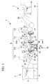
FIG. 2] FIG. 2 is a cross-section view taken from line X - X ofFIG. 1 . - [
FIG. 3] FIG. 3 is an elevation view showing a general structure of an air utilization system according to the first embodiment of the present invention, seen from its drive side. - [
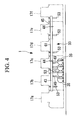
FIG. 4] FIG. 4 is an elevation view showing a general structure of an air utilization system according to a different embodiment of the present invention, seen from its drive side. - [
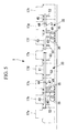
FIG. 5] FIG. 5 is an elevation view showing a general structure of an air utilization system according to a further different embodiment of the present invention, seen from its drive side. - [
FIG. 6] FIG. 6 is a schematic view showing the structure of an intermediate cylinder portion according to a second embodiment of the present invention. - [
FIG. 7] FIG. 7 is a cross-section view taken from line Y - Y ofFIG. 6 . - [
FIG. 8] FIG. 8 is an elevation view showing a general structure of an air utilization system according to the second embodiment of the present invention, seen from its drive side. - [
FIG. 9] FIG. 9 is a cross-section view taken from line Z - Z ofFIG. 8 . -
- 1: sheet-fed printing press
- 3: sheet feeding apparatus
- 5: printing section
- 7: sheet delivery apparatus
- 11: sheet
- 35: blower
- 37: header pipe
- 39: air shower
- 47, 95: attachment member
- 49: air supply tube
- 51, 85: connection member
- 59, 87: control valve
- 53: pneumatic tubing
- 63: air chamber
- 71: chamber-air supply tube
- Embodiments of the present invention will be described below with reference to the attached drawings.
- A first embodiment of the present invention will be described with reference to
FIGS. 1 to 3 .
This embodiment is an application of the present invention to a sheet-fed offset press (printing press) 1 for printing on thick sheets.
FIG. 1 is an elevation view of a general whole structure of the sheet-fed offset press 1 seen from its drive side.
The sheet-fed offset press 1 includes a sheet feeding apparatus 3, aprinting section 5 and a sheet delivery apparatus (sheet delivery portion) 7. - The sheet feeding apparatus 3 includes a sheet feeding table 9, a sheet feeding mechanism (not shown),
sheet feeding rollers 13 and afeeder board 15.
The sheet feeding table 9 is structured to be movable in an up-and-down direction, and holds sheets (printing sheets) 11 in a stacked state.
The sheet feeding mechanism picks up thesheets 11 one by one from a stack thereof and feeds them to thesheet feeding rollers 13.
The sheet feeding table 9 is constructed to move upward in response to the feeding of thesheets 11 so that the distance between the sheet feeding mechanism and thesheets 11 can be maintained substantially constant. - The
sheet feeding rollers 13 are formed of a pair of rollers and have a function to feed thesheets 11, fed by the sheet feeding mechanism, onto thefeeder board 15 by holding them between the rollers.
At the downstream end of thefeeder board 15, there are provided a front gauge and a side gauge, both of which control the attitude and position of thesheets 11.
Further, on the downstream side of thefeeder board 15, there is provided a transfer member such as, for example, a swing gripper or the like, which transfers thesheets 11 to theprinting section 5 by allowing them to be accelerated. - The
printing section 5 includesprinting units
Theprinting units
Since theprinting units - The
printing unit 17a includes aplate cylinder 19, arubber cylinder 21, animpression cylinder 23 and anintermediate cylinder 25. Theintermediate cylinder 25 has a cylindrical shape.
Each of theprinting units plate cylinder 19, arubber cylinder 21, animpression cylinder 23 and anintermediate cylinder 27.
Theplate cylinder 19,rubber cylinder 21 andimpression cylinder 23 are disposed in this order from top to bottom so as to contact each other, and as shown inFIG. 1 , therubber cylinder 21 is located so as to deviate from the position directly above theimpression cylinder 23 toward the upstream side in the direction of transporting thesheets 11.
A print plate for forming a print image is attached on the outer surface of theplate cylinder 19. Around theplate cylinder 19, although not shown, there are provided an ink apparatus for supplying ink onto an image line portion of the print plate and a dampening apparatus for supplying dampening water onto a non-image line portion of the print plate. - A blanket constructed of elastic material is attached on the outer surface of the
rubber cylinder 21. Therubber cylinder 21 reprints a print image on thesheets 11, the print image having been formed on the print plate and reprinted from theplate cylinder 19 onto therubber cylinder 21.
Theimpression cylinder 23 has a diameter being twice as much as that of theplate cylinder 19 and also therubber cylinder 21; that is so called a double-sized cylinder.
On the outer surface of theimpression cylinder 23, two gripper devices (not shown) are provided to be positioned across the center axis of theimpression cylinder 23. - The
intermediate cylinder 27 is disposed in the upstream side of theimpression cylinder 23. Theintermediate cylinder 27 is of a skeleton type and is provided with gripper devices at both ends thereof.
Thesheets 11 are transported through theprinting units intermediate cylinders impression cylinders 23. - The sheet delivery apparatus 7 includes a
chain gripper 29 and a sheet delivery table 31.
Thechain gripper 29, which includes a pair of chains circulating between a position adjacent to theimpression cylinder 23 of theprinting unit 17d and a position above the sheet delivery table 31, gripping bars connecting the pair of chains, and gripper devices attached to the respective gripping bars with a predetermined space, receives the sheets from theimpression cylinder 23 of theprinting unit 17d and transports them to the position above the sheet delivery table 31.
The sheet delivery table 31 is structured to be able to move in an up-and-down direction, and holds the sheets delivered from thechain gripper 29 in a stacked state.
The sheet delivery table 31 is controlled to move downward gradually so that the falling distance of the sheets would be substantially constant. - On the drive side of the
printing section 5, there is provided anair utilizing system 33. Theair utilizing system 33 will now be described with reference toFIGS. 2 and3 .
Theair utilizing system 33 includes blowers (pneumatic machines) 35, a header pipe (tank body) 37 and air showers (air utilizing means) 39.
Theheader pipe 37 is installed on the outside of adrive side frame 41 of the sheet-fed offset press 1 by spacing apart therefrom so as to extend in the direction of transporting thesheets 11.
Theheader pipe 37 is disposed between the rear end of theprinting unit 17a and the front of theprinting unit 17d in a substantially horizontal position. - The
header pipe 37 is composed of asupply module 43 and a first utilization module (utilization module) 45.
Thesupply module 43 andfirst utilization module 45 are both pipe members having a cylindrical shape and connected by a connectingflange 44 so as to become a through pipe.
Thesupply module 43 has a length extending from the rear end of theprinting unit 17a to the rear of theprinting unit 17c.
Thesupply module 43 is provided withattachment members 47 for connecting anair supply tube 49 of each of theblowers 35 at four positions apart from each other in a longitudinal direction on the underside thereof. - On the underside of the
supply module 43, twoconnection members 51 for connectingpneumatic tubing 53 are fixed at positions corresponding to the respective front portion of theprinting units
Thefirst utilization module 45 has a length extending from the rear of theprinting unit 17c to the front of theprinting unit 17d and covers the length of one printing unit.
On the underside of thefirst utilization module 45, aconnection member 51 for connecting thepneumatic tubing 53 is fixed at a position corresponding to the front portion of theprinting unit 17d. - The
printing units air shower 39, which is installed at a position from theintermediate cylinder 27 to therubber cylinder 21 so as to face theimpression cylinder 23.
Theair shower 39 includes ajet pipe 55, which has the substantially same length as that of theimpression cylinder 23 and is disposed to extend along the axis line thereof, andjet nozzles 57 disposed at positions apart from each other by a predetermined space in a longitudinal direction on thejet pipe 55 so as to face theimpression cylinder 23.
Thejet pipe 55 is connected to theheader pipe 37 using thepneumatic tubing 53.
On theheader pipe 37 side of thepneumatic tubing 53, there is provided acontrol valve 59, the open/close degree of which can be remotely controlled.
Since being installed to extend in the moving direction of thesheets 11, theheader pipe 37 can deal with theair showers 39 distributed in the moving direction of the printing sheets. - The number of units of the
blower 35 is determined by considering the capacity to cover the maximum volume of air to be delivered to each of the three units of theair shower 39. In the case of this embodiment, two units of theblower 35 are provided.
One end of theair supply tube 49 of each of theblowers 35 is connected to one of theattachment members 47. Theattachment members 47 having noair supply tube 49 connected thereto will be closed. - It is noted that although the
first utilization module 45 is solely used in this embodiment, asecond utilization module 61 is provided for the case that the number of printing unit is increased (seeFIGS. 4 and5 ).
Thesecond utilization module 61 is provided with twoconnection members 51 for each connecting thepneumatic tubing 53, and covers two printing units. - The operation of the above sheet-fed offset press 1 according to this embodiment will now be described.
First, the printing operation of the sheet-fed offset press 1 will be described.
Thick sheets 11 loaded on the sheet feeding table 9 of the sheet feeding apparatus 3 are taken out from the top thereof one by one by the sheet feeding mechanism, and are fed to a nip portion of thesheet feeding rollers 13. The position of thesheets 11 transported on thefeeder board 15 by thesheet feeding rollers 13 are adjusted by a front gauge and a side gauge provided at the downstream end of thefeeder board 15. - The sheets stopped at the front gauge are gripped and swung by the swing gripper toward a continuously rotating
intermediate cylinder 25 so as to be accelerated.
Therespective sheets 11 gripped by the swing gripper are transferred to the gripper device of theintermediate cylinder 25 to be gripped thereby and are further transferred to the gripper device of theimpression cylinder 23 to be gripped thereby.
In theprinting unit 17a, a dampening apparatus supplies water onto a non-image line portion of a print plate attached on the outer surface of theplate cylinder 19, and an ink supplying apparatus supplies ink onto an image line portion of the print plate.
A print image on the print plate thus obtained is reprinted on therubber cylinder 21.
The print image reprinted on therubber cylinder 21 is reprinted on therespective sheets 11, which are transported by theimpression cylinder 23; the printing of the first color is thus carried out. - The
sheets 11 on which the first color has been printed in theprinting unit 17a are transferred from theimpression cylinder 23 of theprinting unit 17a to theintermediate cylinder 27 of theprinting unit 17b and further to theimpression cylinder 23 of theprinting unit 17b.
In theprinting unit 17b, as with theprinting unit 17a, a print image formed on theplate cylinder 19 and reprinted on therubber cylinder 21 is reprinted on thesheets 11, and thereby the printing of the second color is carried out.
The same process as described above is repeated in theprinting units - After being printed in
printing section 5, thesheets 11 are transferred from theimpression cylinder 23 of theprinting unit 17b to thechain gripper 29 to be gripped. The sheets transported by thechain gripper 29 are released at a position above the sheet delivery table 31, fall on the top of the sheet delivery table 31, and are piled thereon.
At this time, a powder is sprayed onto thesheets 11 to prevent undried ink from adhering onto the backside of thesheets 11. - Next, the operation of the
air utilizing system 33 will be described.
Since athick sheet 11 has strong elasticity, there is a fear that when the thick sheet is transferred from the skeleton typeintermediate cylinder 27 to theimpression cylinder 23, a free end portion of each of the sheets bounces on theimpression cylinder 23 and hits theintermediate cylinder 27, which may cause a scratch thereon.
Theair utilizing system 33 suppresses the bounce of the sheets.
During printing operation, two units of theblower 35 are driven and compressed air is taken in from theblowers 35 to theheader pipe 37 via theair supply tubes 49. - The air collected in the
header pipe 37 is taken in thejet pipes 55 via thepneumatic tubing 53 and is jetted from thejet nozzles 57 against the sheets being transported around therespective impression cylinders 23, and thereby the sheets are pushed onto therespective impression cylinders 23.
Since the air from two units of theblower 35 is thus collected in theheader pipe 37 and used by three units of theair shower 39, even if one unit of theblower 35 fails, the remaining one unit of theblower 35 can supply air to theair showers 39 disposed at three places.
Accordingly, although the maximum volume of air cannot be delivered from theair showers 39, a minimal volume of air is secured, so the printing operation can be carried out without being interrupted. - Moreover, since a margin of air volume required for the three units of the
air shower 39 is shared by the two units of theblower 35, the capacity of one blower unit can be reduced and the utilization efficiency of theblowers 35 can be thereby increased.
In addition, since the air volume supplied to theair showers 39 is reduced by halting one of two units of theblower 39, capacity control of theair showers 39 is accomplished only by on/off of theblower 35 without discharging excess air; thereby power-conservation can be achieved. The more the number of theblowers 35 increases, the more the merit of power-conservation becomes great. - It is possible to operate
respective control valves 59 from a control section to implement a required printing by adjusting the air volume delivered to therespective air showers 39, the control section being located on the sheet delivery side to control the operation of the sheet-fed offset press 1 while watching the state of printed sheet.
In addition, since thesupply module 43 is disposed on the side of the sheet feeding apparatus 3 and theblowers 39 are collectively disposed, a worker can easily approach theblowers 39 and do inspection work therefor.
Incidentally, further power-conservation can be achieved by using an inverter for controlling the motor for driving each of theblowers 35. - It should be noted that although being described to be applied to a sheet-fed offset press 1 for four-color printing in this embodiment, the present invention is not limited to this application.
For example, the present invention may be applied to a sheet-fed offset press 1 for six-color printing, which has sixprinting units
In this sheet-fed offset press 1, aheader pipe 37 is constructed so as to cover from theprinting unit 17b to theprinting unit 17f by connecting asupply module 43, asecond utilization module 61 and afirst utilization module 45.
Four units of theblower 35 are provided, taking consideration of the capacity to cover the maximum volume of air delivered to each of the five units of theair shower 39. - The present invention may also be applied to a sheet-fed offset press 1 for eight-color printing, which has eight
printing units
In this case, two systems of theair utilizing system 33 are employed, taking the pressure loss in theheader pipe 37 into account.
In theair utilizing system 33 on the side of the sheet feeding apparatus 3, theheader pipe 37 is constructed so as to cover from theprinting unit 17b to theprinting unit 17e by connecting asupply module 43 and asecond utilization module 61. - Three units of the
blower 35 are provided, taking consideration of the capacity to cover the maximum volume of air delivered to each of the four units of theair shower 39.
In theair utilizing system 33 on the side of the sheet delivery apparatus, theheader pipe 37 is constructed so as to cover from theprinting unit 17f to theprinting unit 17h by connecting thesupply module 43 and afirst utilization module 45.
Two units of theblower 35 are provided, taking consideration of the capacity to cover the maximum volume of air delivered to each of the three units of theair shower 39. - Since being thus constructed by combining the
supply module 43,first utilization module 45 and/orsecond utilization module 61, theheader pipe 37 can be adapted to sheet-fed offset press 1 having different length in the moving direction of the printing sheets by adjusting the combination. - Next, a second embodiment of the present invention will be described with reference to
FIGS. 6 to 9 .
The basic structure of this embodiment is identical to that of the first embodiment except that a sheet-fed offset press 1 is provided with anair utilizing system 33 additionally havingair chambers 63 for dual-purpose of thin sheet/thick sheet printing. Accordingly, only different points will be described in this embodiment, and duplicated description of the other part will be omitted.
The same constitutional elements as those in the first embodiment are indicated by identical reference characters, and detailed descriptions thereof are omitted. - A sheet-fed offset press 1 according to this embodiment is provided with
air chambers 63 for guidingthin sheets 11 in addition to the structure of the first embodiment, theair chambers 63 being each disposed along a peripheral path of a skeleton typeintermediate cylinder 27.
Each of theair chambers 63 is a box-like member curved in an arc shape of the peripheral path of theintermediate cylinder 27, as shown inFIG. 6 .
Each of theair chambers 63 includeschambers 65, jet holes 69 and dischargingportions 73. Thechambers 65 have a width larger than that of thesheet 11 and are each constructed to extend in the moving direction of thesheets 11. - The
intermediate cylinder 27 side of thechambers guide surface 67 for guiding thesheets 11. On theguide surface 67, there are provide a multiple of jet holes 69 for jetting air in thechambers 65 outward at the upstream side in the direction of transporting thesheets 11.
A chamber-air supply tube (air supply tube) 71 for supplying air is connected to each of thechambers 65.
On both sides of thechambers 65, there are provided the dischargingportions 73 for substantially recovering the air jetted from the jet holes 69.
Chamber recovery tubes 75 for drawing and recovering the air are connected to the dischargingportions 73, respectively. - A
header pipe 37 is a pipe member having a rectangular cross-sectional shape. On the printing unit 17 side of theheader pipe 37, there is provided asuction header pipe 77 having the substantially same shape as theheader pipe 37 with a space therefrom.
Theheader pipe 37 is composed of asupply module 79, afirst utilization module 81 and asecond utilization module 83 so as to become a through pipe.
Thesupply module 79 is provided withattachment members 47 for connecting respectiveair supply tubes 49 of theblowers 35 at four positions apart from each other in a longitudinal direction on the outer side thereof.
On the underside of thesupply module 43, aconnection member 51 for connectingpneumatic tubing 53 is fixed at a position corresponding to the front portion of theprinting unit 17b, and aconnection member 85 for connecting a chamber-air supply tube 71 is also fixed at a position corresponding to the rear portion of theprinting unit 17b. - On the underside of the
first utilization module 81, theconnection member 51 for connecting thepneumatic tubing 53 is fixed at a position corresponding to the front portion of theprinting unit 17c, and theconnection member 85 for connecting the chamber-air supply tube 71 is also fixed at a position corresponding to the rear portion of theprinting unit 17c.
On the underside of thesecond utilization module 83, theconnection member 51 for connecting thepneumatic tubing 53 is fixed at a position corresponding to the front portion of theprinting unit 17d, and theconnection member 85 for connecting the chamber-air supply tube 71 is also fixed at a position corresponding to the rear portion of theprinting unit 17d.
On theheader pipe 37 side of each of the chamber-air supply tubes 71, there are provided acontrol valve 87, an open/close degree of which can be remotely controlled, and asilencer 89. -
Connection members 91 for each connecting achamber recovery tube 75 are fixed on the underside of thesuction header pipe 77.
Thesuction header pipe 77 is connected to the suction side of theblowers 35 byair suction tubes 93.
Theair suction tubes 93 are each connected to anattachment member 95 provided on the underside of thesuction header pipe 77.
Afilter 97 for collecting waste, dirt, dust and the like, which are included in the suction air, is installed in midstream of theair suction tube 93. - The operation of the sheet-fed offset press 1 constituted as described above, according to this embodiment, will now be described.
The printing operation and the operation of theair utilizing system 33 in the case ofthick sheets 11 are identical to those of the first embodiment, so duplicated description will be omitted and the operation of theair utilizing system 33 in the case ofthin sheets 11 will be described.
In the case when thethin sheets 11 are handled, thecontrol valves 59 are closed so that air is not supplied to theair showers 39.
Then, the degree of opening ofrespective control valves 87 is regulated so that the air is supplied to thechambers air supply tubes 71. - During printing operation, two units of the
blower 35 are driven and compressed air is taken in from theblowers 35 to theheader pipe 37 via theair supply tubes 49.
The air collected in theheader pipe 37 is taken in thechambers 65 through the respectivechamber supply tubes 71. The air taken into thechambers 65 is jetted from jet holes 69, flows along theguide surface 67 toward the upstream side in the sheet transport direction and also toward the outside of the sheets, and is recovered into the dischargingportions 73.
The sheets being transported around theintermediate cylinder 27 are attracted to the air flow flowing along theguide surface 67, pulled toward the upstream side in the sheet transport direction and also toward the outside of the sheets, controlled their position, and transferred to thenext impression cylinder 23. - The air recovered into the discharging
portions 73 is collected to thesuction header pipe 77 through thechamber recovery tubes 75.
The air collected to thesuction header pipe 77 is taken into the suction side of each of the blowers through theair suction tubes 93; the dust or the like in the air is removed in midstream by thefilter 97.
It is possible to operate therespective control valves 87 from a control section to implement a required printing by adjusting the air volume delivered to therespective air chambers 63, the control section being located on the sheet delivery side to control the operation of the sheet-fed offset press 1 while watching the state of printed matter. - The processes and effects described as to the operation of the
air utilizing system 33 of the first embodiment are similarly applied to the case of the sheet-fed offset press 1 according to this embodiment, so duplicated description will be omitted here.
Since being constructed by combining thesupply module 79,first utilization module 81 and/orsecond utilization module 83, theheader pipe 37 is adaptable to sheet-fed offset press 1 having different length in the moving direction of the printing sheets by adjusting the combination similarly as with the first embodiment.
Claims (6)
- A printing press comprising:a plurality of pneumatic machines each having an air supply tube for supplying air;a tank body to which the air supply tubes of all the pneumatic machines are connected; anda plurality of air utilization means for executing predetermined processes using air supplied from the tank body through pneumatic tubing, by which the respective air utilization means are connected to the tank body.
- The printing press according to Claim 1,
wherein the tank body has a tubular structure and is installed to extend in the moving direction of printing sheets. - The printing press according to Claim 1 or 2,
wherein the tank body is constructed by combining a supply module including a plurality of attachment members, to which the air supply tubes are attached, and a predetermined number of utilization modules each including only a connection member for the pneumatic tubing. - The printing press according to Claim 3,
wherein the supply module includes a connection member for the pneumatic tubing. - The printing press according to Claim 3 or 4,
wherein the supply module is disposed on the side of a sheet feeding apparatus or on the side of a sheet delivery apparatus. - The printing press according to any one of Claims 1 to 5,
wherein the pneumatic tubing is provided with control valves therein, the open/close degree of which can be remotely controlled.
Applications Claiming Priority (2)
| Application Number | Priority Date | Filing Date | Title |
|---|---|---|---|
| JP2006051449A JP2007229969A (en) | 2006-02-28 | 2006-02-28 | Printing machine |
| PCT/JP2007/052869 WO2007099792A1 (en) | 2006-02-28 | 2007-02-16 | Printing machine |
Publications (2)
| Publication Number | Publication Date |
|---|---|
| EP1990296A1 true EP1990296A1 (en) | 2008-11-12 |
| EP1990296A4 EP1990296A4 (en) | 2009-11-18 |
Family
ID=38458905
Family Applications (1)
| Application Number | Title | Priority Date | Filing Date |
|---|---|---|---|
| EP07714399A Withdrawn EP1990296A4 (en) | 2006-02-28 | 2007-02-16 | Printing machine |
Country Status (5)
| Country | Link |
|---|---|
| US (1) | US20090255430A1 (en) |
| EP (1) | EP1990296A4 (en) |
| JP (1) | JP2007229969A (en) |
| CN (1) | CN101341085A (en) |
| WO (1) | WO2007099792A1 (en) |
Families Citing this family (1)
| Publication number | Priority date | Publication date | Assignee | Title |
|---|---|---|---|---|
| JP6384987B2 (en) * | 2014-05-22 | 2018-09-05 | 株式会社小森コーポレーション | Sheet-fed printing press |
Family Cites Families (13)
| Publication number | Priority date | Publication date | Assignee | Title |
|---|---|---|---|---|
| US4371309A (en) * | 1981-02-25 | 1983-02-01 | Principe William L | Air table |
| JPS6133470A (en) * | 1984-07-26 | 1986-02-17 | Murata Mach Ltd | Central blower in winder |
| US4702644A (en) * | 1986-05-16 | 1987-10-27 | Cioffi Dominic A | Truck mounted roller |
| US4919048A (en) * | 1986-08-01 | 1990-04-24 | Tyler Jack D | Apparatus for preventing contact of wet ink sheets with printing press delivery mechanisms and for drying said wet ink |
| JPH08118599A (en) * | 1994-10-26 | 1996-05-14 | Toppan Printing Co Ltd | Paper break prevention device in rotary printing press |
| DE19624716A1 (en) * | 1996-06-21 | 1996-11-21 | Voith Sulzer Papiermasch Gmbh | Winding machine for coiling moving paper web |
| JPH11107923A (en) * | 1997-10-02 | 1999-04-20 | Chuo Giken:Kk | air compressor |
| US6170819B1 (en) * | 1998-08-05 | 2001-01-09 | Baldwin Graphic Systems, Inc. | Non-contact sheet handling system and method of using same |
| DE19945272B4 (en) * | 1999-09-22 | 2004-03-11 | Baldwin Germany Gmbh | Compressed air supply device of a printing press or a sheet handling device |
| DE10190901D2 (en) * | 2000-03-16 | 2005-09-15 | Becker Kg Gebr | Method and device for use in a suction / compressed air supply waste heat accumulating on a printing press |
| DE20008740U1 (en) * | 2000-05-17 | 2000-08-24 | Platsch, Hans G., 70565 Stuttgart | Hot air drying device |
| JP2002264296A (en) * | 2001-03-08 | 2002-09-18 | Mitsubishi Heavy Ind Ltd | Sheet delivering equipment |
| JP2003118072A (en) * | 2001-10-12 | 2003-04-23 | Mitsubishi Heavy Ind Ltd | Sheet guide device for sheet-feed press and method for controlling sheet guide device |
-
2006
- 2006-02-28 JP JP2006051449A patent/JP2007229969A/en not_active Withdrawn
-
2007
- 2007-02-16 CN CNA200780000762XA patent/CN101341085A/en active Pending
- 2007-02-16 US US11/990,187 patent/US20090255430A1/en not_active Abandoned
- 2007-02-16 WO PCT/JP2007/052869 patent/WO2007099792A1/en not_active Ceased
- 2007-02-16 EP EP07714399A patent/EP1990296A4/en not_active Withdrawn
Also Published As
| Publication number | Publication date |
|---|---|
| JP2007229969A (en) | 2007-09-13 |
| CN101341085A (en) | 2009-01-07 |
| WO2007099792A1 (en) | 2007-09-07 |
| EP1990296A4 (en) | 2009-11-18 |
| US20090255430A1 (en) | 2009-10-15 |
Similar Documents
| Publication | Publication Date | Title |
|---|---|---|
| JP3363234B2 (en) | Sheet-fed rotary printing press | |
| JP4275211B2 (en) | Sheet-fed rotary press | |
| US20040163557A1 (en) | Sheet-fed press and intermediate cylinder for sheet-fed press | |
| CN103057250A (en) | Combination printing press | |
| JP3331248B2 (en) | Rotary printing press for double-sided printing of sheets | |
| JP2000053303A5 (en) | ||
| CN100526073C (en) | Apparatus for conveying a sheet through a printing machine | |
| US20090255430A1 (en) | Printing Press | |
| JP3935797B2 (en) | Sheet-fed printing press | |
| JP7118786B2 (en) | Printer | |
| JP3964304B2 (en) | Sheet material guide device | |
| CN100503241C (en) | Sheet-fed offset printing press with reversible printing mechanism | |
| JP5242932B2 (en) | How to spray powder on printed sheets | |
| JP5433261B2 (en) | Sheet material guide device | |
| US6264190B1 (en) | Suction unit in sheet-fed rotary printing press | |
| EP1088654A1 (en) | Printing machine | |
| JP2008239278A (en) | Sheet printer | |
| JP2003118072A (en) | Sheet guide device for sheet-feed press and method for controlling sheet guide device | |
| JP4061107B2 (en) | Sheet material guide device | |
| US20080265493A1 (en) | Air delivery device for printing and coating applications | |
| DE102011084212B4 (en) | Pre-gripper of a processing machine for sheet material | |
| JP2009208911A (en) | Curl removing device and single-side and double-side sheet-fed printing press | |
| JP4452284B2 (en) | Sheet-fed printing press | |
| JP2008213181A (en) | Recording medium conveying device and printing machine | |
| DE19723146A1 (en) | Printer sheet ream guide |
Legal Events
| Date | Code | Title | Description |
|---|---|---|---|
| PUAI | Public reference made under article 153(3) epc to a published international application that has entered the european phase |
Free format text: ORIGINAL CODE: 0009012 |
|
| 17P | Request for examination filed |
Effective date: 20080205 |
|
| AK | Designated contracting states |
Kind code of ref document: A1 Designated state(s): DE |
|
| DAX | Request for extension of the european patent (deleted) | ||
| RBV | Designated contracting states (corrected) |
Designated state(s): DE |
|
| A4 | Supplementary search report drawn up and despatched |
Effective date: 20091019 |
|
| STAA | Information on the status of an ep patent application or granted ep patent |
Free format text: STATUS: THE APPLICATION HAS BEEN WITHDRAWN |
|
| 18W | Application withdrawn |
Effective date: 20100120 |