EP1990142A1 - Razor - Google Patents
Razor Download PDFInfo
- Publication number
- EP1990142A1 EP1990142A1 EP07708364A EP07708364A EP1990142A1 EP 1990142 A1 EP1990142 A1 EP 1990142A1 EP 07708364 A EP07708364 A EP 07708364A EP 07708364 A EP07708364 A EP 07708364A EP 1990142 A1 EP1990142 A1 EP 1990142A1
- Authority
- EP
- European Patent Office
- Prior art keywords
- blade
- base
- razor
- supporting portion
- bodies
- Prior art date
- Legal status (The legal status is an assumption and is not a legal conclusion. Google has not performed a legal analysis and makes no representation as to the accuracy of the status listed.)
- Granted
Links
Images




Classifications
-
- B—PERFORMING OPERATIONS; TRANSPORTING
- B26—HAND CUTTING TOOLS; CUTTING; SEVERING
- B26B—HAND-HELD CUTTING TOOLS NOT OTHERWISE PROVIDED FOR
- B26B21/00—Razors of the open or knife type; Safety razors or other shaving implements of the planing type; Hair-trimming devices involving a razor-blade; Equipment therefor
- B26B21/08—Razors of the open or knife type; Safety razors or other shaving implements of the planing type; Hair-trimming devices involving a razor-blade; Equipment therefor involving changeable blades
- B26B21/14—Safety razors with one or more blades arranged transversely to the handle
- B26B21/22—Safety razors with one or more blades arranged transversely to the handle involving several blades to be used simultaneously
- B26B21/222—Safety razors with one or more blades arranged transversely to the handle involving several blades to be used simultaneously with the blades moulded into, or attached to, a changeable unit
- B26B21/225—Safety razors with one or more blades arranged transversely to the handle involving several blades to be used simultaneously with the blades moulded into, or attached to, a changeable unit the changeable unit being resiliently mounted on the handle
-
- B—PERFORMING OPERATIONS; TRANSPORTING
- B26—HAND CUTTING TOOLS; CUTTING; SEVERING
- B26B—HAND-HELD CUTTING TOOLS NOT OTHERWISE PROVIDED FOR
- B26B21/00—Razors of the open or knife type; Safety razors or other shaving implements of the planing type; Hair-trimming devices involving a razor-blade; Equipment therefor
- B26B21/08—Razors of the open or knife type; Safety razors or other shaving implements of the planing type; Hair-trimming devices involving a razor-blade; Equipment therefor involving changeable blades
- B26B21/14—Safety razors with one or more blades arranged transversely to the handle
- B26B21/22—Safety razors with one or more blades arranged transversely to the handle involving several blades to be used simultaneously
- B26B21/222—Safety razors with one or more blades arranged transversely to the handle involving several blades to be used simultaneously with the blades moulded into, or attached to, a changeable unit
- B26B21/227—Safety razors with one or more blades arranged transversely to the handle involving several blades to be used simultaneously with the blades moulded into, or attached to, a changeable unit with blades being resiliently mounted in the changeable unit
Definitions
- the present invention relates to a structure for supporting a blade body in a razor head in a razor provided with the razor head having the blade body.
- Patent Document 1 discloses a movable blade-body type safety razor having the following configuration.
- the safety razor is provided with a blade base having a frame body and a top plate placed on the blade base.
- the frame body is provided with a guard, a back frame portion located at the back of the guard, and side frame portions located on both right and left sides of the guard.
- a plurality of elastic arms and a plurality of blade body placing portions are disposed inside the frame body, and the elastic arms and the blade body placing portions are coupled to each other.
- the top plate is provided with holding portions at positions corresponding to each blade body.
- An objective of the present invention is to provide a razor having a simple configuration.
- a razor having a razor head.
- the razor head is provided with a blade member composed of a base having a blade-body supporting portion, a blade base member located on the back side of the razor head, and a top member located on the front side of the razor head.
- the blade member is fitted between the blade base member and the top member, the base of the blade member is supported on the blade base member, and a cutting edge of the blade body is exposed outward at the top member.
- the blade body is placed on the blade-body supporting portion of the base and also attached to the blade-body supporting portion by welding.
- a single-component blade member in which the blade body is welded to the blade-body supporting portion of the base is fitted between the blade base member and the top member, by which a structure for supporting the blade body is simplified and also the blade body is easily attached to the blade-body supporting portion of the base.
- the single-component blade member means that the blade member is separated from the blade base member and the top member. If the single-component blade member is provided with a plurality of blade bodies, it is acceptable that at least some of the blade bodies are attached to the blade-body supporting portions of the base by welding. Alternatively, all the blade bodies may be attached to the blade-body supporting portions by welding. Further, some of the blade bodies may be attached to the blade-body supporting portions by welding while the remaining blade bodies are formed integrally with the blade-body supporting portions.
- a razor having a razor head.
- the razor head is provided with a blade base member, a blade member, and a skin surface contact portion.
- the blade base member is located on the back side of the razor head.
- the blade member is supported on the blade base member.
- the blade member includes a base having a blade-body supporting portion and a blade body exposed outward on the front side of the razor head.
- the skin surface contact portion contacts a skin surface together with a cutting edge of the blade body.
- the blade body is placed on the blade-body supporting portion of the base, and welded portions fixed to each other by welding from a side corresponding to the blade-body supporting portion are disposed in the blade body and the blade-body supporting portion.
- the blade body is welded to the blade-body supporting portion from the side corresponding to the blade-body supporting portion, the blade body is easily attached to the blade-body supporting portion of the base, thus simplifying the structure for supporting the blade body. Further, since the blade body is not directly welded to the front side, no welded spots are visible on the front side of the blade body.
- the thickness of the blade-body supporting portion is set to be greater than the thickness of the blade body. This configuration increases the rigidity of the blade-body supporting portion.
- the welding is laser welding. According to this configuration, the blade body can be easily attached to the blade-body supporting portion of the base.
- the base of the blade member is provided with a pair of mutually facing placing bodies and also a placing base supported on the blade base member.
- the blade-body supporting portion is constructed between a pair of placing bodies. According this configuration simplifies the structure of the blade member.
- the blade member is preferably provided with a plurality of blade bodies.
- the blade-body supporting portion of the base is provided with a plurality of blade body attaching portions arranged parallel in a staircase pattern along a direction orthogonal to a direction in which the cutting edge of the blade body extends.
- a plurality of the blade bodies are placed on each of the blade body attaching portions and attached to each of the blade body attaching portions by welding. According to this configuration, each blade body can be easily attached to the blade-body supporting portion of the base.
- a razor having a razor head.
- the razor head includes a blade base member, a blade member, and a skin surface contact portion.
- the blade base member is located on the back side of the razor head.
- the blade member is supported on the blade base member.
- the blade member includes a base having a blade-body supporting portion and a placing base, and a plurality of blade bodies exposed outward on the front side of the razor head.
- the skin surface contact portion contacts a skin surface together with the cutting edges of the blade bodies.
- the blade-body supporting portion and the placing base are formed integrally.
- the blade bodies are placed on the blade-body supporting portions of the base, and also attached to the blade-body supporting portions by welding.
- each blade body is welded to the blade-body supporting portion of the base at which the blade-body supporting portion and the placing base are formed integrally. This simplifies the structure for supporting the blade bodies and allows the blade body to be easily attached to the blade-body supporting portion of the base.
- the welding is laser welding. According to this configuration, the blade body can be easily attached to the blade-body supporting portion of the base.
- the placing base of the base is provided with a pair of mutually facing placing bodies and also supported on the blade base member.
- the blade-body supporting portion is constructed between the placing bodies. According this configuration simplifies the structure of the blade member.
- the blade-body supporting portion of the base is provided with a plurality of blade body attaching portions arranged parallel in a staircase pattern along a direction orthogonal to a direction in which the cutting edge of the blade body extends.
- the blade bodies are placed individually on the blade body attaching portions and also attached individually to the blade body attaching portions by welding. According to this configuration, each blade body can be easily attached to the blade-body supporting portion of the base.
- the blade base member is also provided with a base plate.
- the base of the blade member is supported on the base plate.
- the base, the blade body and the base plate are made of metal materials.
- the base plate is made of a metal material having an ionization tendency higher than those of the metal materials of the base and the blade body. According to this configuration, the base plate is oxidized earlier than the blade body, thereby preventing the blade body from being rusted.
- an oscillating razor 1 is provided with a razor head 2 and a holder 40.
- the razor head 2 is provided with a blade member 3 having a plurality of metal-made blade bodies 4, a blade base member 5 located on the back side of the razor head 2, and a top member 6 located on the front side of the razor head 2.
- the blade member 3 is fitted between the blade base member 5 and the top member 6.
- a metal which forms the blade body 4 includes, for example, martensite stainless steel.
- the number of blade bodies 4 are, for example, four.
- the blade member 3 is provided with a base 7 located on the back side of the blade body 4.
- the base 7 is formed by a placing base 8 composed of leaf springs 9 as placing bodies, or supporting edge portions.
- the placing base 8 is disposed at both end portions in a direction orthogonal to a direction in which the cutting edge 4a of each blade body 4 extends, that is, the X axis direction given in Fig. 6(a) and a blade-body supporting portion 10 constructed between the leaf springs 9.
- Each of the leaf springs 9 is provided with a supporting plate 11 extending in a direction in which the cutting edge 4a of the blade body 4 extends, that is, the Y axis direction given in Fig. 6(a) .
- each supporting plate 11 in the Y axis direction is bent toward the blade base member 5 to form leg plates 12 as leg portions.
- a deflection allowance space 13 is defined between each supporting plate 11 and each leg plate 12.
- the placing base 8 and the blade-body supporting portion 10 which form the base 7 are formed integrally with each other by subjecting a plate material made of a metal, for example, austenite stainless steel, to press working.
- the length of the base 7 of the present embodiment in the X axis direction is about 9 mm
- the length of the base 7 in the Y axis direction is about 34 mm.
- the blade-body supporting portion 10 is formed by a blade body attaching plate 14 composed of step plates 16 as a plurality of blade body attaching portions arranged parallel along the X axis direction and a plurality of cross-link arm portions 15 arranged parallel along the Y axis direction from both edge portions of the blade body attaching plate 14 in the X axis direction.
- step plates 16 are arranged parallel and four cross-link arm portions 15 are also arranged parallel.
- the step plates 16 are arranged parallel so as to give a staircase pattern, and a plurality of through holes 17 are arranged parallel along the Y axis direction between mutually adjacent step plates 16. With the strength of the blade body attaching plate 14 taken into account, the length of the through holes 17 the Y axis direction is reduced toward both end portions in the Y axis direction.
- Each of the cross-link arm portions 15 is bent toward each of the leaf springs 9, and a space is defined internally at the blade body attaching plate 14.
- Each cross-link arm portion 15 is coupled to the supporting plate 11 of each leaf spring 9 and formed integrally with the supporting plate 11.
- a space defined inside the placing base 8 of the base 7 is opened outward to the placing base 8 through an opening 19 located on the back side of the placing base 8 and an opening 20 located on the front side of the placing base 8, thereby forming a debris discharge hole 18.
- the opening 19 is formed by a space defined by each of end portions 12a on a plane connecting the end portions 12a of each leg plate 12 on each leaf spring 9.
- the opening 20 is formed by each through hole 17 of the blade body attaching plate 14 and spaces defined in front of and behind, and to the right and left of the blade body attaching plate 14 .
- the debris discharge hole 18 is opened outward to the placing base 8 in front of and behind, and to the left of the placing base 8.
- the blade body 4 is placed on each step plate 16 of the blade body attaching plate 14 so as to extend along the Y axis direction.
- laser welding by YAG laser or carbon dioxide gas laser is given from the step plate 16 to the blade body 4 at a plurality of spots, thereby forming on the blade body 4 and the step plate 16 welded portions R at which the blade body 4 and the step plate 16 are fixed to each other.
- Rust preventive oil is applied to the surface of the blade body 4. The surface is not directly welded on the step plate 16, thus making it possible to prevent the surface of the blade body 4 from being contaminated by welding at the welded portions R.
- Laser welding is given in a state where each step plate 16 is placed on a blade body 4 set on a jig.
- the thickness of the step plate 16, or T16 is set to be greater than the thickness of the blade body 4, or T4.
- T16, or the thickness of the step plate 16 is in a range between 0.1 mm and 0.5 mm, inclusive, for example, and preferably in a range between 0.12 mm and 0.20 mm, inclusive.
- T4, or the thickness of the blade body 4 is in a range between 0.05 mm and 0.3 mm, inclusive, for example, and preferably in a range between 0.07 mm and 0.15 mm, inclusive.
- T16 In order to impart an appropriate rigidity and suppress the thermal strain, T16, or the thickness of the step plate 16, is experimentally determined to be 0.15 mm as a design value in a range between 0.12 mm and 0.20 mm, inclusive. This thickness of T16 is determined with possible hardening of a material in association with press working of the base 7 taken into account.
- Each pitch between the welded portions R in the Y axis direction is about 3 mm.
- each of the welded portions R is formed at the same site on each of mutually adjacent blade bodies 4. However, on each of the mutually adjacent blade bodies 4, welded portions R of the other blade body 4 may be formed between individual welded portions R of one blade body 4.
- the blade bodies 4 are arranged in a staircase pattern on the blade body attaching plate 14, and the cutting edge 4a of each blade body 4 is projected outward and forward from each step plate 16.
- a back edge portion 4b of the blade body 4 at the front is located in the vicinity of a site corresponding to a cutting edge 4a of the blade body 4 at the back.
- a clearance 21 facing each of the through holes 17 on the blade body attaching plate 14 is formed between the cutting edge 4a of the blade body 4 at the back and the back edge portion 4b of the blade body 4 at the front.
- the blade base member 5 is formed by a bottom base 22 made of plastic and a base plate 23 made of aluminum.
- the base plate 23 be made of a metal material higher in ionization tendency than that of the material forming the base 7 and that of the material forming the blade bodies 4.
- the thickness of the base plate 23 of the present embodiment is about 0.3 mm.
- the bottom base 22 is provided with a frame portion 24, and the frame portion 24 is provided with a front frame portion 24a located at the front, a back frame portion 24b at the back, a left frame portion 24c on the left, and a right frame portion 24d on the right as edge portions.
- stoppers 24e on the left frame portion 24c and the right frame portion 24d are projected toward the blade body attaching plate 14 of the blade-body supporting portion 10.
- a debris discharge hole 25 is formed by a space enclosed by the frame portion 24.
- the base plate 23 is placed on the bottom base 22. Specifically, the frame portion 26 of the base plate 23 is superimposed on the frame portion 24 of the bottom base 22, and the through hole 27 of the base plate 23 communicates with the debris discharge hole 25 of the bottom base 22.
- the top member 6 is made of plastic and provided with a frame portion 28.
- a blade body exposure hole 29 is formed by a space enclosed by the frame portion 28.
- the frame portion 28 is formed by a front frame portion 28a, a back frame portion 28b, a left frame portion 28c, and a right frame portion 28d as edge portions.
- a shaving aid is attached to the front frame portion 28a and the back frame portion 28b.
- each leg plate 12 of each leaf spring 9 of the base 7 is placed on both front and back frame portions 26a, 26b on the base plate 23 of the blade base member 5.
- Each leaf spring 9 of the base 7 is inserted into a clearance 32 between both front and back frame portions 24a, 24b on the bottom base 22 of the blade base member 5 and both front and the back frame portions 28a, 28b on the top member 6, thus hidden from outside.
- the blade bodies 4 are arranged in a staircase pattern along the X axis direction by the blade-body supporting portion 10, and both left and right end portions thereof are inserted between both left and right frame portions 24c, 24d on the bottom base 22 of the blade base member 5 and both left and right frame portions 28c, 28d on the top member 6.
- Each blade body 4 is pressed against both left and right frame portions 28c, 28d on the top member 6 by an elastic force of each leaf spring 9.
- each blade body 4 is located in the vicinity of a shaving tangential plane 34 passing through a skin surface contact portion 33 formed on both front and back frame portion 28a and 28b of the top member 6.
- a straight line connecting the cutting edge 4a with the back edge portion 4b is inclined relative to the shaving tangential plane 34.
- Each blade body 4 moves integrally with the blade-body supporting portion 10 along the Z axis direction orthogonal to the shaving tangential plane 34 against the elastic force of each leaf spring 9.
- the debris discharge hole 18 formed inside the placing base 8 of the base 7 communicates with the through hole 27 on the base plate 23 of the blade base member 5 and with the debris discharge hole 25 on the bottom base 22 through the opening 19, and also communicating with the blade body exposure hole 29 on the top member 6 through the opening 20.
- each of the blade bodies 4 is welded to the blade-body supporting portion 10, and the blade member 3 is fitted between the blade base member 5 and the top member 6, thus simplifying the structure for supporting each of the blade bodies 4.
- holder 40 in the holder 40, supporting arms 42 and pushers 43 are projected forward from both left and right sides of the head portion 41 of the holder 40 in a state where they are arranged side by side.
- recesses 44 are formed at the back of both left and right frame portions 24c, 24d on the bottom base 22 of the blade base member 5 of the razor head 2, and the debris discharge hole 25 is opened between the recesses 44.
- Figs. 7(a) and 7(b) in the holder 40, supporting arms 42 and pushers 43 are projected forward from both left and right sides of the head portion 41 of the holder 40 in a state where they are arranged side by side.
- recesses 44 are formed at the back of both left and right frame portions 24c, 24d on the bottom base 22 of the blade base member 5 of the razor head 2, and the debris discharge hole 25 is opened between the recesses 44.
- each supporting arm 42 is supported by each recess 44, and the razor head 2 is detachably supported to the head portion 41 of the holder 40 in a state where each recess 44 is pressed by each pusher 43.
- the razor head 2 is oscillatable vertically about each supporting arm 42 against an elastic force of each pusher 43.
- an initial clearance G between the blade body attaching plate 14 and each stopper 24e is preferably in a range between 0.1 mm and 1.2 mm, and set to be 0.5 mm in the present embodiment.
- the force is preferably from 0.784 to 1.372 N (80 to 140 gf) for about a 0.3 mm displacement of the blade body 4 and from 1.078 to 1.666 N (110 to 170 gf) for about a 0.5 mm displacement of the blade body 4.
- Debris generated at each blade body 4 are advanced from the opening 20 into the debris discharge hole 18 and discharged from the opening 19 into the debris discharge hole 25 of the blade base member 5 in the blade member 3.
- the holder 40 may be disposed integrally with the razor head 2.
- the holder 40 is formed integrally with the bottom base 22.
- the skin surface contact portions 33 may be disposed on the blade base member 5, instead of on the top member 6. Of,these skin surface contact portions 33 of the top member 6, the skin surface contact portion 33 located at the front of the top member 6 may be omitted and another skin surface contact portion 33 may be disposed on the blade base member 5. Of these skin surface contact portions 33 of the top member 6, the skin surface contact portion 33 located at the back of the top member 6 may be omitted, and another skin surface contact portion 33 may be disposed on the blade base member 5.
- the leaf springs 9 may be disposed not only at the front and back of the placing base 8 but also on the left and right thereof.
- the leaf springs 9 at the front and back of the placing base 8 may be omitted, and another set of leaf springs 9 may be disposed on the left and right.
- each leaf spring 9 as a placing body may be omitted and the placing body may be formed by using an elasticity-free member.
- a plurality of rods for example, square rods, round rods and other shapes of rods may be arrayed in a lattice form and bent to form the base 7.
- the laser welding for example, resistance welding, ultrasonic welding, electron beam welding, and plasma welding may be used.
- a laser is only radiated from the side corresponding to the blade-body supporting portion 10.
- the laser welding is simpler in preparing welding equipment than such welding that is performed with the blade-body supporting portion 10 and the blade body 4 held between other members.
- Each leg plate 12 of each leaf spring 9 may be changed in spring constant by changing the width in the front-back direction or thickness.
- the leg plates 12 may have different spring constants, so that elastic displacement vary among the blade bodies 4.
- a cutting edge may be provided at the back edge portion 4b, in addition to the cutting edge 4a located at the front edge portion of each blade body 4, and a cutting edge located at the back edge portion 4b may be exposed outward.
- a pair of blade body attaching plates 14 formed in a staircase pattern may be arranged parallel along the X axis direction.
- the cutting edge 4a of each blade body 4 located at the front is exposed at a blade body exposure hole 29 on the top member 6 due to the blade body attaching plate 14 located at the front.
- the cutting edge 4a of each blade body 4 located at the back is exposed at the blade body exposure hole 29 of the top member 6 due to the blade body attaching plate 14 located at the back.
- the number of the blade bodies 4 may be changed to five, six or eight, for example, other than four blade bodies at the blade-body supporting portion 10 of the base 7.
- a blade body attaching plate 14 formed in a staircase pattern is divided into two pieces in the front-back direction.
- An appropriate number of the blade bodies 4 are arranged on the blade body attaching plate 14 located at the front.
- the remaining number of the blade bodies 4 are arranged on the blade body attaching plate 14 located at the back.
- the blade body attaching plate 14 may be divided into two pieces to attach the blade body attaching plate 14 located at the front to the blade body attaching plate 14 located at the back.
Landscapes
- Life Sciences & Earth Sciences (AREA)
- Forests & Forestry (AREA)
- Engineering & Computer Science (AREA)
- Mechanical Engineering (AREA)
- Dry Shavers And Clippers (AREA)
Abstract
Description
- The present invention relates to a structure for supporting a blade body in a razor head in a razor provided with the razor head having the blade body.
-
Patent Document 1 discloses a movable blade-body type safety razor having the following configuration. Specifically, the safety razor is provided with a blade base having a frame body and a top plate placed on the blade base. The frame body is provided with a guard, a back frame portion located at the back of the guard, and side frame portions located on both right and left sides of the guard. A plurality of elastic arms and a plurality of blade body placing portions are disposed inside the frame body, and the elastic arms and the blade body placing portions are coupled to each other. On the blade body placing portions at the front and on the blade body placing portions at the back, blade bodies are placed individually. The top plate is provided with holding portions at positions corresponding to each blade body. Each blade body is held between the corresponding blade body placing portions and the corresponding holding portion, and movable together with each blade body placing portion and the top plate against the elasticity of each of the elastic arms.
However, the structure for supporting the blade body described inPatent Document 1, has the following problem. That is, since each blade body is held between a blade body placing portion coupled to an elastic arm and a holding portion of the top plate, it is troublesome to form the blade base having the elastic arms and the blade body placing portions. Also, since the top plate moves together with the blade bodies, the structure of a razor is complicated.
Patent Document 1: Japanese Patent No.2963824 - An objective of the present invention is to provide a razor having a simple configuration.
- According to one aspect of the present invention, there is provided a razor having a razor head. The razor head is provided with a blade member composed of a base having a blade-body supporting portion, a blade base member located on the back side of the razor head, and a top member located on the front side of the razor head. The blade member is fitted between the blade base member and the top member, the base of the blade member is supported on the blade base member, and a cutting edge of the blade body is exposed outward at the top member. The blade body is placed on the blade-body supporting portion of the base and also attached to the blade-body supporting portion by welding.
- According to the above configuration, a single-component blade member in which the blade body is welded to the blade-body supporting portion of the base is fitted between the blade base member and the top member, by which a structure for supporting the blade body is simplified and also the blade body is easily attached to the blade-body supporting portion of the base. The single-component blade member means that the blade member is separated from the blade base member and the top member. If the single-component blade member is provided with a plurality of blade bodies, it is acceptable that at least some of the blade bodies are attached to the blade-body supporting portions of the base by welding. Alternatively, all the blade bodies may be attached to the blade-body supporting portions by welding. Further, some of the blade bodies may be attached to the blade-body supporting portions by welding while the remaining blade bodies are formed integrally with the blade-body supporting portions.
- According to another aspect of the present invention, there is provided a razor having a razor head. The razor head is provided with a blade base member, a blade member, and a skin surface contact portion. The blade base member is located on the back side of the razor head. The blade member is supported on the blade base member. The blade member includes a base having a blade-body supporting portion and a blade body exposed outward on the front side of the razor head. The skin surface contact portion contacts a skin surface together with a cutting edge of the blade body. The blade body is placed on the blade-body supporting portion of the base, and welded portions fixed to each other by welding from a side corresponding to the blade-body supporting portion are disposed in the blade body and the blade-body supporting portion.
- According to the above configuration, since the blade body is welded to the blade-body supporting portion from the side corresponding to the blade-body supporting portion, the blade body is easily attached to the blade-body supporting portion of the base, thus simplifying the structure for supporting the blade body. Further, since the blade body is not directly welded to the front side, no welded spots are visible on the front side of the blade body.
- It is preferable that, at the welded portions, the thickness of the blade-body supporting portion is set to be greater than the thickness of the blade body. This configuration increases the rigidity of the blade-body supporting portion.
- It is preferable that the welding is laser welding. According to this configuration, the blade body can be easily attached to the blade-body supporting portion of the base.
- It is preferable that the base of the blade member is provided with a pair of mutually facing placing bodies and also a placing base supported on the blade base member. In this instance, the blade-body supporting portion is constructed between a pair of placing bodies. According this configuration simplifies the structure of the blade member.
- The blade member is preferably provided with a plurality of blade bodies. In this instance, the blade-body supporting portion of the base is provided with a plurality of blade body attaching portions arranged parallel in a staircase pattern along a direction orthogonal to a direction in which the cutting edge of the blade body extends. Further, a plurality of the blade bodies are placed on each of the blade body attaching portions and attached to each of the blade body attaching portions by welding. According to this configuration, each blade body can be easily attached to the blade-body supporting portion of the base.
- According to still another aspect of the present invention, there is provided a razor having a razor head. The razor head includes a blade base member, a blade member, and a skin surface contact portion. The blade base member is located on the back side of the razor head. The blade member is supported on the blade base member. The blade member includes a base having a blade-body supporting portion and a placing base, and a plurality of blade bodies exposed outward on the front side of the razor head. The skin surface contact portion contacts a skin surface together with the cutting edges of the blade bodies. The blade-body supporting portion and the placing base are formed integrally. The blade bodies are placed on the blade-body supporting portions of the base, and also attached to the blade-body supporting portions by welding.
- According to the above configuration, each blade body is welded to the blade-body supporting portion of the base at which the blade-body supporting portion and the placing base are formed integrally. This simplifies the structure for supporting the blade bodies and allows the blade body to be easily attached to the blade-body supporting portion of the base.
- It is preferable that the welding is laser welding. According to this configuration, the blade body can be easily attached to the blade-body supporting portion of the base.
- It is preferable that the placing base of the base is provided with a pair of mutually facing placing bodies and also supported on the blade base member. In this instance, the blade-body supporting portion is constructed between the placing bodies. According this configuration simplifies the structure of the blade member.
- It is preferable that the blade-body supporting portion of the base is provided with a plurality of blade body attaching portions arranged parallel in a staircase pattern along a direction orthogonal to a direction in which the cutting edge of the blade body extends. In this instance, the blade bodies are placed individually on the blade body attaching portions and also attached individually to the blade body attaching portions by welding. According to this configuration, each blade body can be easily attached to the blade-body supporting portion of the base.
- It is preferable that the blade base member is also provided with a base plate. In this instance, the base of the blade member is supported on the base plate. Further, the base, the blade body and the base plate are made of metal materials. The base plate is made of a metal material having an ionization tendency higher than those of the metal materials of the base and the blade body. According to this configuration, the base plate is oxidized earlier than the blade body, thereby preventing the blade body from being rusted.
-
-
Fig. 1(a) is a perspective view of an oscillating razor of the present embodiment, as viewed from the back side; -
Fig. 1(b) is a perspective view of the oscillating razor, as viewed from the front side; -
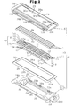
Fig. 2 is an exploded perspective view of a razor head of the oscillating razor; -
Fig. 3(a) is a perspective view of a blade member in which each blade body is attached to a base; -
Fig. 3(b) is a perspective view of a blade base member in which a base plate is placed on a bottom base; -
Fig. 3(c) is a perspective view showing a state in which the base of the blade member is placed on the base plate of the blade base member; -
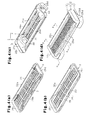
Fig. 4(a) is a perspective view showing a state in which the blade member is fitted into a top member; -
Fig. 4(b) is a perspective view showing a state in which the blade member and the base plate are fitted into the top member; -
Figs. 4(c) and 4(d) are perspective views showing the razor head in its entirety; -
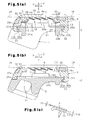
Fig. 5 (a) is an enlarged cross-sectional view taken along line 5a-5a inFig. 4(d) ; -
Fig. 5(b) is an enlarged cross-sectional view taken along line 5b-5b inFig. 4(d) ; -
Fig. 5(c) is a partially enlarged view ofFig. 5(a) ; -
Fig. 6(a) is a front elevational view of the razor head; -
Fig. 6(b) is a rear view of the razor head;Fig. 7(a) is a plan view showing the head of a holder -
Fig. 7(b) is a side elevational view showing the head of the holder; -
Fig. 8(a) is a side elevational view showing a state in which the razor head is supported on the head of the holder; and -
Fig. 8(b) is a partial cross-sectional view showing a structure for supporting the razor head relative to each supporting arm of the holder and a pressure-contact structure of the pusher of the holder relative to the razor head. - Hereinafter, a description will be given of an oscillating razor according to one embodiment of the present invention by referring to drawings. As shown in
Figs. 1(a) and 1(b) , anoscillating razor 1 is provided with arazor head 2 and aholder 40. As shown inFigs. 1(a) to 6(b) , therazor head 2 is provided with ablade member 3 having a plurality of metal-madeblade bodies 4, ablade base member 5 located on the back side of therazor head 2, and atop member 6 located on the front side of therazor head 2. Theblade member 3 is fitted between theblade base member 5 and thetop member 6. A metal which forms theblade body 4 includes, for example, martensite stainless steel. The number ofblade bodies 4 are, for example, four. - As shown in
Fig. 2 , theblade member 3 is provided with abase 7 located on the back side of theblade body 4. Thebase 7 is formed by a placingbase 8 composed ofleaf springs 9 as placing bodies, or supporting edge portions. The placingbase 8 is disposed at both end portions in a direction orthogonal to a direction in which thecutting edge 4a of eachblade body 4 extends, that is, the X axis direction given inFig. 6(a) and a blade-body supporting portion 10 constructed between the leaf springs 9. Each of theleaf springs 9 is provided with a supportingplate 11 extending in a direction in which thecutting edge 4a of theblade body 4 extends, that is, the Y axis direction given inFig. 6(a) . - Both end portions of each supporting
plate 11 in the Y axis direction, that is, both right and left end portions of each supportingplate 11, are bent toward theblade base member 5 to formleg plates 12 as leg portions. As shown inFig. 3(c) , adeflection allowance space 13 is defined between each supportingplate 11 and eachleg plate 12. The placingbase 8 and the blade-body supporting portion 10 which form thebase 7 are formed integrally with each other by subjecting a plate material made of a metal, for example, austenite stainless steel, to press working. The length of thebase 7 of the present embodiment in the X axis direction is about 9 mm, and the length of thebase 7 in the Y axis direction is about 34 mm. - As shown in
Fig. 2 , the blade-body supporting portion 10 is formed by a bladebody attaching plate 14 composed ofstep plates 16 as a plurality of blade body attaching portions arranged parallel along the X axis direction and a plurality ofcross-link arm portions 15 arranged parallel along the Y axis direction from both edge portions of the bladebody attaching plate 14 in the X axis direction. In the present embodiment, fourstep plates 16 are arranged parallel and fourcross-link arm portions 15 are also arranged parallel. - As shown in
Figs. 2 and5(a) , thestep plates 16 are arranged parallel so as to give a staircase pattern, and a plurality of throughholes 17 are arranged parallel along the Y axis direction between mutuallyadjacent step plates 16. With the strength of the bladebody attaching plate 14 taken into account, the length of the throughholes 17 the Y axis direction is reduced toward both end portions in the Y axis direction. Each of thecross-link arm portions 15 is bent toward each of theleaf springs 9, and a space is defined internally at the bladebody attaching plate 14. Eachcross-link arm portion 15 is coupled to the supportingplate 11 of eachleaf spring 9 and formed integrally with the supportingplate 11. - As shown in
Fig. 5(a) , a space defined inside the placingbase 8 of thebase 7 is opened outward to theplacing base 8 through anopening 19 located on the back side of the placingbase 8 and anopening 20 located on the front side of the placingbase 8, thereby forming adebris discharge hole 18. Theopening 19 is formed by a space defined by each ofend portions 12a on a plane connecting theend portions 12a of eachleg plate 12 on eachleaf spring 9. Theopening 20 is formed by each throughhole 17 of the bladebody attaching plate 14 and spaces defined in front of and behind, and to the right and left of the bladebody attaching plate 14 . Thedebris discharge hole 18 is opened outward to theplacing base 8 in front of and behind, and to the left of the placingbase 8. - As shown in
Figs. 5(a) to 5(c) , theblade body 4 is placed on eachstep plate 16 of the bladebody attaching plate 14 so as to extend along the Y axis direction. For example, laser welding by YAG laser or carbon dioxide gas laser is given from thestep plate 16 to theblade body 4 at a plurality of spots, thereby forming on theblade body 4 and thestep plate 16 welded portions R at which theblade body 4 and thestep plate 16 are fixed to each other. Rust preventive oil is applied to the surface of theblade body 4. The surface is not directly welded on thestep plate 16, thus making it possible to prevent the surface of theblade body 4 from being contaminated by welding at the welded portions R. Laser welding is given in a state where eachstep plate 16 is placed on ablade body 4 set on a jig. - At the welded portion R, the thickness of the
step plate 16, or T16, is set to be greater than the thickness of theblade body 4, or T4. T16, or the thickness of thestep plate 16, is in a range between 0.1 mm and 0.5 mm, inclusive, for example, and preferably in a range between 0.12 mm and 0.20 mm, inclusive. T4, or the thickness of theblade body 4, is in a range between 0.05 mm and 0.3 mm, inclusive, for example, and preferably in a range between 0.07 mm and 0.15 mm, inclusive. When a great quantity of heat resulting from welding is applied to thestep plate 16, thermal strain will easily develop on thestep plate 16. - In order to impart an appropriate rigidity and suppress the thermal strain, T16, or the thickness of the
step plate 16, is experimentally determined to be 0.15 mm as a design value in a range between 0.12 mm and 0.20 mm, inclusive. This thickness of T16 is determined with possible hardening of a material in association with press working of thebase 7 taken into account. Each pitch between the welded portions R in the Y axis direction is about 3 mm. As shown inFigs. 6(a) and 6(b) , in the present embodiment, each of the welded portions R is formed at the same site on each of mutuallyadjacent blade bodies 4. However, on each of the mutuallyadjacent blade bodies 4, welded portions R of theother blade body 4 may be formed between individual welded portions R of oneblade body 4. - As shown in
Figs. 4(d) and5(a) , theblade bodies 4 are arranged in a staircase pattern on the bladebody attaching plate 14, and thecutting edge 4a of eachblade body 4 is projected outward and forward from eachstep plate 16. Regarding each of the mutuallyadjacent blade bodies 4, aback edge portion 4b of theblade body 4 at the front is located in the vicinity of a site corresponding to acutting edge 4a of theblade body 4 at the back. Aclearance 21 facing each of the throughholes 17 on the bladebody attaching plate 14 is formed between thecutting edge 4a of theblade body 4 at the back and theback edge portion 4b of theblade body 4 at the front. - As shown in
Fig. 2 , theblade base member 5 is formed by abottom base 22 made of plastic and abase plate 23 made of aluminum. In a case where thebase 7, theblade bodies 4, and thebase plate 23 are made of metal materials, it is preferable that thebase plate 23 be made of a metal material higher in ionization tendency than that of the material forming thebase 7 and that of the material forming theblade bodies 4. The thickness of thebase plate 23 of the present embodiment is about 0.3 mm. Thebottom base 22 is provided with aframe portion 24, and theframe portion 24 is provided with afront frame portion 24a located at the front, aback frame portion 24b at the back, aleft frame portion 24c on the left, and aright frame portion 24d on the right as edge portions. - As shown in
Figs. 3(b) and 3(c) ,stoppers 24e on theleft frame portion 24c and theright frame portion 24d are projected toward the bladebody attaching plate 14 of the blade-body supporting portion 10. Adebris discharge hole 25 is formed by a space enclosed by theframe portion 24. Thebase plate 23 is placed on thebottom base 22. Specifically, theframe portion 26 of thebase plate 23 is superimposed on theframe portion 24 of thebottom base 22, and the throughhole 27 of thebase plate 23 communicates with thedebris discharge hole 25 of thebottom base 22. - As shown in
Figs. 2 and5(a) , thetop member 6 is made of plastic and provided with aframe portion 28. A bladebody exposure hole 29 is formed by a space enclosed by theframe portion 28. Theframe portion 28 is formed by afront frame portion 28a, aback frame portion 28b, aleft frame portion 28c, and aright frame portion 28d as edge portions. A shaving aid is attached to thefront frame portion 28a and theback frame portion 28b. - In a state where the
blade member 3 is fitted between theblade base member 5 and thetop member 6, theframe portion 24 of theblade base member 5 and theframe portion 28 of thetop member 6 are superimposed on each other. Then, both front andback frame portions blade base member 5 are mutually engaged with both front andback frame portions top member 6 by each of locking recesses/projections 30 (recesses 30a andprojections 30b). Further, an instant adhesive agent is applied to theblade base member 5 and thetop member 6 or applied between theblade base member 5 and thetop member 6, by which theblade base member 5 and thetop member 6 are bonded together. - As shown in
Figs. 3(c) and5(a) , in theblade member 3 located between theblade base member 5 and thetop member 6, eachleg plate 12 of eachleaf spring 9 of thebase 7 is placed on both front andback frame portions base plate 23 of theblade base member 5. Eachleaf spring 9 of thebase 7 is inserted into aclearance 32 between both front andback frame portions bottom base 22 of theblade base member 5 and both front and theback frame portions top member 6, thus hidden from outside. As shown inFigs. 4(a) to 4(d) ,6(a), and 6(b) , theblade bodies 4 are arranged in a staircase pattern along the X axis direction by the blade-body supporting portion 10, and both left and right end portions thereof are inserted between both left andright frame portions bottom base 22 of theblade base member 5 and both left andright frame portions top member 6. Eachblade body 4 is pressed against both left andright frame portions top member 6 by an elastic force of eachleaf spring 9. - As shown in
Figs. 5(a) and 5(b) , thecutting edge 4a of eachblade body 4 is located in the vicinity of a shavingtangential plane 34 passing through a skinsurface contact portion 33 formed on both front andback frame portion top member 6. In eachblade body 4, a straight line connecting thecutting edge 4a with theback edge portion 4b is inclined relative to the shavingtangential plane 34. Eachblade body 4 moves integrally with the blade-body supporting portion 10 along the Z axis direction orthogonal to the shavingtangential plane 34 against the elastic force of eachleaf spring 9. - In the
blade member 3, thedebris discharge hole 18 formed inside the placingbase 8 of thebase 7 communicates with the throughhole 27 on thebase plate 23 of theblade base member 5 and with thedebris discharge hole 25 on thebottom base 22 through theopening 19, and also communicating with the bladebody exposure hole 29 on thetop member 6 through theopening 20. - When assembling the
top member 6, theblade member 3, thebottom base 22, and thebase plate 23 of theblade base member 5, first, as shown inFig. 4(a) , theblade member 3 is superimposed on thetop member 6, thereafter, as shown inFig. 4(b) , thebase plate 23 is superimposed on theblade member 3, and as shown inFig. 4(c) , thebottom base 22 is then superimposed on thebase plate 23 and bonded to thetop member 6. In this instance, each of theblade bodies 4 is welded to the blade-body supporting portion 10, and theblade member 3 is fitted between theblade base member 5 and thetop member 6, thus simplifying the structure for supporting each of theblade bodies 4. - As shown in
Figs. 7(a) and 7(b) , in theholder 40, supportingarms 42 andpushers 43 are projected forward from both left and right sides of thehead portion 41 of theholder 40 in a state where they are arranged side by side. As shown inFig. 2 , recesses 44 are formed at the back of both left andright frame portions bottom base 22 of theblade base member 5 of therazor head 2, and thedebris discharge hole 25 is opened between therecesses 44. As shown inFigs. 8(a) and 8(b) , each supportingarm 42 is supported by eachrecess 44, and therazor head 2 is detachably supported to thehead portion 41 of theholder 40 in a state where eachrecess 44 is pressed by eachpusher 43. Therazor head 2 is oscillatable vertically about each supportingarm 42 against an elastic force of eachpusher 43. - When the
oscillating razor 1 is used in a state where each of skinsurface contact portions 33 of thetop member 6 contacts the skin surface together with eachblade body 4, eachleaf spring 9 deflects against a pressing force given to eachblade body 4, by which eachblade body 4 is allowed to move elastically. As shown inFigs. 5(a) and 5(b) , an initial clearance G between the bladebody attaching plate 14 and eachstopper 24e is preferably in a range between 0.1 mm and 1.2 mm, and set to be 0.5 mm in the present embodiment. When the bladebody attaching plate 14 is displaced only by this initial clearance G and contacts each of thestoppers 24e, eachblade body 4 stops moving. - When a force is applied to the blade
body attaching plate 14 along the Z axis direction orthogonal to the shavingtangential plane 34, the force is preferably from 0.784 to 1.372 N (80 to 140 gf) for about a 0.3 mm displacement of theblade body 4 and from 1.078 to 1.666 N (110 to 170 gf) for about a 0.5 mm displacement of theblade body 4. Debris generated at eachblade body 4 are advanced from theopening 20 into thedebris discharge hole 18 and discharged from theopening 19 into thedebris discharge hole 25 of theblade base member 5 in theblade member 3. - The above embodiment may be modified as follows.
- The
holder 40 may be disposed integrally with therazor head 2. In this instance, for example, theholder 40 is formed integrally with thebottom base 22. - The skin
surface contact portions 33 may be disposed on theblade base member 5, instead of on thetop member 6. Of,these skinsurface contact portions 33 of thetop member 6, the skinsurface contact portion 33 located at the front of thetop member 6 may be omitted and another skinsurface contact portion 33 may be disposed on theblade base member 5. Of these skinsurface contact portions 33 of thetop member 6, the skinsurface contact portion 33 located at the back of thetop member 6 may be omitted, and another skinsurface contact portion 33 may be disposed on theblade base member 5. - The
leaf springs 9 may be disposed not only at the front and back of the placingbase 8 but also on the left and right thereof. Theleaf springs 9 at the front and back of the placingbase 8 may be omitted, and another set ofleaf springs 9 may be disposed on the left and right. Further, eachleaf spring 9 as a placing body may be omitted and the placing body may be formed by using an elasticity-free member. - A plurality of rods, for example, square rods, round rods and other shapes of rods may be arrayed in a lattice form and bent to form the
base 7. - In addition to the laser welding, for example, resistance welding, ultrasonic welding, electron beam welding, and plasma welding may be used. In the laser welding, a laser is only radiated from the side corresponding to the blade-
body supporting portion 10. Thus, the laser welding is simpler in preparing welding equipment than such welding that is performed with the blade-body supporting portion 10 and theblade body 4 held between other members. - Each
leg plate 12 of eachleaf spring 9 may be changed in spring constant by changing the width in the front-back direction or thickness. Theleg plates 12 may have different spring constants, so that elastic displacement vary among theblade bodies 4. - A cutting edge may be provided at the
back edge portion 4b, in addition to thecutting edge 4a located at the front edge portion of eachblade body 4, and a cutting edge located at theback edge portion 4b may be exposed outward. - At the blade-
body supporting portion 10 of thebase 7, a pair of bladebody attaching plates 14 formed in a staircase pattern may be arranged parallel along the X axis direction. In this instance, thecutting edge 4a of eachblade body 4 located at the front is exposed at a bladebody exposure hole 29 on thetop member 6 due to the bladebody attaching plate 14 located at the front. Thecutting edge 4a of eachblade body 4 located at the back is exposed at the bladebody exposure hole 29 of thetop member 6 due to the bladebody attaching plate 14 located at the back. - The number of the
blade bodies 4 may be changed to five, six or eight, for example, other than four blade bodies at the blade-body supporting portion 10 of thebase 7. In this instance, a bladebody attaching plate 14 formed in a staircase pattern is divided into two pieces in the front-back direction. An appropriate number of theblade bodies 4 are arranged on the bladebody attaching plate 14 located at the front. The remaining number of theblade bodies 4 are arranged on the bladebody attaching plate 14 located at the back. Further, the bladebody attaching plate 14 may be divided into two pieces to attach the bladebody attaching plate 14 located at the front to the bladebody attaching plate 14 located at the back.
Claims (11)
- A razor comprising a razor head, wherein the razor head includes:a blade member having a blade body and a base with a blade-body supporting portion;a blade base member located on the back side of the razor head; anda top member located on the front side of the razor head,the razor being characterized in that the blade member is fitted between the blade base member and the top member, the base of the blade member is supported on the blade base member, a cutting edge of the blade body is exposed outward at the top member,wherein the blade body is placed on the blade-body supporting portion of the base and attached to the blade-body supporting portion by welding.
- A razor comprising a razor head, wherein the razor head includes:a blade base member located on the back side of the razor head;a blade member supported on the blade base member, the blade member including a base having a blade-body supporting portion and a blade body exposed outward on the front side of the razor head; anda skin surface contact portion which contacts a skin surface together with a cutting edge of the blade body,the razor being characterized in that the blade body is placed on the blade-body supporting portion of the base, and welded portions fixed to each other by welding from a side corresponding to the blade-body supporting portion are disposed in the blade body and the blade-body supporting portion.
- The razor according to claim 2, wherein, at the welded portions, the thickness of the blade-body supporting portion is set to be greater than the thickness of the blade body.
- The razor according to any one of claims 1 to 3,
wherein the welding is laser welding. - The razor according to any one of claims 1 to 4,
wherein the base of the blade member is provided with a pair of mutually facing placing bodies and also a placing base supported on the blade base member, and the blade-body supporting portion is constructed between the pair of placing bodies. - The razor according to any one of claims 1 to 5,
wherein the blade member is provided with a plurality of blade bodies,
wherein the blade-body supporting portion of the base is provided with a plurality of blade body attaching portions arranged parallel in a staircase pattern along a direction orthogonal to a direction in which the cutting edge of the blade body extends, and
wherein the blade bodies are placed on each of the blade body attaching portions and also attached to each of the blade body attaching portions by welding. - A razor comprising a razor head, wherein the razor head includes:a blade base member located on the back side of the razor head;a blade member supported on the blade base member, the blade member including a base having a blade-body supporting portion and a placing base, and a plurality of blade bodies exposed outward on the front side of the razor head; anda skin surface contact portion which contacts a skin surface together with the cutting edges of the blade bodies;the razor being characterized in that the blade-body supporting portion and the placing base are formed integrally, and the blade bodies are placed on the blade-body supporting portions of the base, and also attached to the blade-body supporting portions by welding.
- The razor according to claim 7, wherein the welding is laser welding.
- The razor according to claim 7 or 8, wherein the placing base of the base is provided with a pair of mutually facing placing bodies and also supported on the blade base member, and the blade-body supporting portion is constructed between the placing bodies.
- The razor according to any one of claims 7 to 9, wherein the blade-body supporting portion of the base is provided with a plurality of blade body attaching portions arranged parallel in a staircase pattern along a direction orthogonal to a direction in which the cutting edge of the blade body extends, and
wherein the blade bodies are placed on each of the blade body attaching portions and also attached to each of the blade body attaching portions by welding. - The razor according to any one of claims 1 to 10, wherein the blade base member is further provided with a base plate,
wherein the base of the blade member is supported on the base plate, and
wherein the base, the blade body and the base plate are made of metal materials, and wherein the base plate is made of a metal material having an ionization tendency higher than those of the metal materials of the base and the blade body.
Applications Claiming Priority (2)
| Application Number | Priority Date | Filing Date | Title |
|---|---|---|---|
| JP2006036665A JP4950507B2 (en) | 2006-02-14 | 2006-02-14 | razor |
| PCT/JP2007/052560 WO2007094337A1 (en) | 2006-02-14 | 2007-02-14 | Razor |
Publications (3)
| Publication Number | Publication Date |
|---|---|
| EP1990142A1 true EP1990142A1 (en) | 2008-11-12 |
| EP1990142A4 EP1990142A4 (en) | 2010-03-31 |
| EP1990142B1 EP1990142B1 (en) | 2011-09-28 |
Family
ID=38371515
Family Applications (1)
| Application Number | Title | Priority Date | Filing Date |
|---|---|---|---|
| EP07708364A Ceased EP1990142B1 (en) | 2006-02-14 | 2007-02-14 | Razor |
Country Status (4)
| Country | Link |
|---|---|
| US (1) | US7992304B2 (en) |
| EP (1) | EP1990142B1 (en) |
| JP (1) | JP4950507B2 (en) |
| WO (1) | WO2007094337A1 (en) |
Cited By (8)
| Publication number | Priority date | Publication date | Assignee | Title |
|---|---|---|---|---|
| WO2009057067A1 (en) | 2007-11-02 | 2009-05-07 | The Gillette Company | Razor blade assembly pre-form |
| US7992304B2 (en) * | 2006-02-14 | 2011-08-09 | Kai R&D Center Co., Ltd. | Razor |
| US8046920B2 (en) | 2006-02-14 | 2011-11-01 | Kai R&D Center Co., Ltd. | Razor |
| US8104179B2 (en) | 2006-02-14 | 2012-01-31 | Kai R&D Center Co., Ltd. | Razor |
| US9289909B2 (en) | 2009-04-15 | 2016-03-22 | Bic-Violex Sa | Razor cartridge and mechanical razor comprising such a cartridge |
| WO2017041845A1 (en) * | 2015-09-09 | 2017-03-16 | Beiersdorf Aktiengesellschaft | Safety razor and blade unit for safety razor |
| WO2021113315A1 (en) * | 2019-12-04 | 2021-06-10 | Mack-Ray, Inc. | Dual sided razor |
| US12544944B2 (en) | 2019-12-04 | 2026-02-10 | Mack-Ray Inc. | Dual sided razor |
Families Citing this family (24)
| Publication number | Priority date | Publication date | Assignee | Title |
|---|---|---|---|---|
| JP5010896B2 (en) | 2006-10-31 | 2012-08-29 | 株式会社貝印刃物開発センター | razor |
| US20080256801A1 (en) * | 2007-04-20 | 2008-10-23 | O'connor William Thomas | Razor cartridge with front pivot axis |
| US9517570B2 (en) * | 2007-04-20 | 2016-12-13 | The Gillette Company | Razor cartridge |
| KR100903191B1 (en) * | 2007-05-31 | 2009-06-17 | 주식회사 도루코 | Shaver |
| JP5465869B2 (en) * | 2008-12-05 | 2014-04-09 | 株式会社貝印刃物開発センター | Replaceable blade razor |
| MX338630B (en) * | 2008-12-19 | 2016-04-26 | Bic Violex Sa | Razor cartridge and mechanical razor comprising such a cartridge. |
| EP2454056B1 (en) * | 2009-07-15 | 2014-03-19 | Eveready Battery Company, Inc. | Razor blade technology |
| KR20110024234A (en) * | 2009-09-01 | 2011-03-09 | 주식회사 도루코 | Shaver cartridges |
| JP5453126B2 (en) * | 2010-01-22 | 2014-03-26 | パナソニック株式会社 | Electric razor |
| JP6093550B2 (en) | 2012-11-06 | 2017-03-08 | 株式会社貝印刃物開発センター | razor |
| JP6293464B2 (en) | 2013-11-27 | 2018-03-14 | 株式会社貝印刃物開発センター | razor |
| EP3083163B1 (en) * | 2013-12-18 | 2020-02-05 | BIC-Violex S.A. | A shaving blade cartridge |
| CA3001659A1 (en) * | 2015-12-17 | 2017-06-22 | Bic Violex S.A. | Shaving head |
| EP3429809B1 (en) | 2016-03-18 | 2021-07-28 | Personal Care Marketing And Research, Inc. | Razor cartridge |
| USD816907S1 (en) | 2016-03-18 | 2018-05-01 | Personal Care Marketing and Research International | Razor frame |
| EP3481608B1 (en) * | 2016-07-06 | 2022-05-25 | BIC Violex Single Member S.A. | Razor system |
| US9993931B1 (en) | 2016-11-23 | 2018-06-12 | Personal Care Marketing And Research, Inc. | Razor docking and pivot |
| CN106625792A (en) * | 2017-02-27 | 2017-05-10 | 贵州裕隆实业有限公司 | Blade support of shaver and blade assembly |
| USD884971S1 (en) | 2019-02-27 | 2020-05-19 | Pcmr International Ltd | Razor cartridge |
| USD884969S1 (en) | 2019-02-27 | 2020-05-19 | Pcmr International Ltd | Combined razor cartridge guard and docking |
| USD884970S1 (en) | 2019-02-27 | 2020-05-19 | PCMR International Ltd. | Razor cartridge guard |
| MX2022005479A (en) * | 2020-10-30 | 2022-06-02 | Kai R&D Center Co Ltd | Razor. |
| US11000960B1 (en) | 2020-11-16 | 2021-05-11 | Personal Care Marketing And Research, Inc. | Razor exposure |
| DE102020130698A1 (en) * | 2020-11-20 | 2022-05-25 | LORD International Co. | Blade unit for a wet razor |
Family Cites Families (68)
| Publication number | Priority date | Publication date | Assignee | Title |
|---|---|---|---|---|
| US554666A (en) * | 1896-02-18 | Hose-coupling | ||
| US3940853A (en) * | 1974-04-19 | 1976-03-02 | The Gillette Company | Shaving unit with blade tensioning means |
| GB1591095A (en) * | 1976-11-16 | 1981-06-17 | Wilkinson Sword Ltd | Shaving units |
| US4403412A (en) * | 1980-08-07 | 1983-09-13 | The Gillette Company | Razor blade assembly |
| US4337575A (en) * | 1980-08-07 | 1982-07-06 | The Gillette Company | Razor blade assembly |
| US4324041A (en) * | 1980-08-07 | 1982-04-13 | The Gillette Company | Razor blade assembly |
| US4403413A (en) * | 1980-10-06 | 1983-09-13 | The Gillette Company | Shaving implement |
| GB2131337B (en) * | 1982-12-07 | 1985-10-30 | Gillette Co | Safety razors |
| JPS6047469A (en) | 1983-08-25 | 1985-03-14 | Matsushita Electronics Corp | semiconductor equipment |
| US4709477A (en) * | 1986-09-02 | 1987-12-01 | Warner-Lambert Company | Blade assembly featuring variable span |
| US4774765A (en) * | 1986-09-02 | 1988-10-04 | Warner-Lambert Company | Blade assembly featuring variable span |
| GB8712785D0 (en) | 1987-06-01 | 1987-07-08 | Gillette Co | Blade units |
| DE8910490U1 (en) * | 1989-09-02 | 1991-01-10 | Wilkinson Sword GmbH, 5650 Solingen | Shaver head of a wet shaver |
| US5416974A (en) | 1990-03-27 | 1995-05-23 | The Gillette Company | Safety razors and blade units therefor |
| GB9006782D0 (en) | 1990-03-27 | 1990-05-23 | Gillette Co | Safety razors and blade units therefor |
| JP3414730B2 (en) | 1990-06-11 | 2003-06-09 | ザ、ジレット、カンパニー | Safety razor |
| JPH0755268B2 (en) | 1991-01-14 | 1995-06-14 | 株式会社貝印刃物開発センター | Safety razor blade assembly |
| JPH0755267B2 (en) | 1991-01-16 | 1995-06-14 | 株式会社貝印刃物開発センター | Safety razor |
| JPH0685828B2 (en) | 1991-01-16 | 1994-11-02 | 株式会社貝印刃物開発センター | Safety razor blade assembly |
| US5070612A (en) * | 1991-05-06 | 1991-12-10 | Michael Abatemarco | Razor blade assembly |
| JP2659628B2 (en) * | 1991-06-07 | 1997-09-30 | 株式会社貝印刃物開発センター | Razor blade support head |
| JP2659629B2 (en) * | 1991-06-07 | 1997-09-30 | 株式会社貝印刃物開発センター | Razor blade support head |
| DE9108212U1 (en) * | 1991-07-03 | 1992-10-29 | Wilkinson Sword GmbH, 5650 Solingen | Shaver head, in particular razor blade unit of a wet shaver |
| DE9108214U1 (en) | 1991-07-03 | 1992-10-29 | Wilkinson Sword GmbH, 5650 Solingen | Shaver head, in particular razor blade unit of a wet shaver |
| DE9108213U1 (en) * | 1991-07-03 | 1992-10-29 | Wilkinson Sword GmbH, 5650 Solingen | Shaver head, in particular razor blade unit of a wet shaver |
| WO1993001917A1 (en) | 1991-07-18 | 1993-02-04 | Warner-Lambert Company | Razor head with variable shaving geometry |
| GB2264888B (en) * | 1992-03-06 | 1995-01-25 | Wilkinson Sword Gmbh | Razor head with flow passages |
| US5377409A (en) * | 1992-10-08 | 1995-01-03 | Warner-Lambert Company | One-push cleaning mechanism for flexible wet-shaving razor unit |
| JP2963824B2 (en) | 1992-10-20 | 1999-10-18 | 株式会社貝印刃物開発センター | Blade body movable safety razor |
| AU5551994A (en) | 1992-11-09 | 1994-06-08 | Warner-Lambert Company | Insert molded dynamic shaving system |
| US5546660A (en) | 1994-09-30 | 1996-08-20 | Warner-Lambert Company | Dynamic razor head |
| US6295734B1 (en) * | 1995-03-23 | 2001-10-02 | The Gillette Company | Safety razors |
| GB9505917D0 (en) | 1995-03-23 | 1995-05-10 | Gillette Co | Safety razors |
| US5666729A (en) | 1995-04-10 | 1997-09-16 | Warner-Lambert Company | Suspended blade shaving system |
| AU2129597A (en) * | 1996-03-27 | 1997-10-17 | Warner-Lambert Company | Shaving system with uniform shaving forces |
| GB9616402D0 (en) | 1996-08-05 | 1996-09-25 | Gillette Co | Safety razors |
| CA2223161A1 (en) | 1997-01-17 | 1998-07-17 | Warner-Lambert Company | Razor heads having independently flexible blades |
| US7200937B2 (en) | 1997-01-17 | 2007-04-10 | Eveready Battery Company, Inc. | Razor head with moveable blade package |
| US5822862A (en) | 1997-01-17 | 1998-10-20 | Warner-Lambert Co. | Suspended blade shaving system |
| GB9703293D0 (en) * | 1997-02-18 | 1997-04-09 | Gillette Co | Safety razors |
| US20030159291A1 (en) * | 1997-07-25 | 2003-08-28 | Gregory Clark | Shaving system with uniform shaving forces |
| JP3209975B2 (en) | 1999-03-18 | 2001-09-17 | 株式会社貝印刃物開発センター | Safety razor |
| US20040118250A1 (en) * | 1999-04-23 | 2004-06-24 | The Gillette Company, A Delaware Corporation | Safety razor |
| JP3515024B2 (en) | 1999-09-17 | 2004-04-05 | 株式会社貝印刃物開発センター | Safety razor |
| EP1163089B1 (en) * | 1999-11-29 | 2003-03-26 | Koninklijke Philips Electronics N.V. | Shaver provided with a shaving head having a sub-frame and a main frame |
| JP4598920B2 (en) | 2000-05-29 | 2010-12-15 | 株式会社貝印刃物開発センター | Blade body clamping structure in a three-blade razor head |
| US20040020053A1 (en) * | 2000-10-16 | 2004-02-05 | The Gillette Company | Safety razors |
| US20030046819A1 (en) * | 2001-01-17 | 2003-03-13 | Frank Ferraro | Razor assembly and cartridge with wash-through holes |
| US7191523B2 (en) * | 2001-07-17 | 2007-03-20 | Kai R&D Center Co., Ltd | Safety razor |
| DE60327993D1 (en) | 2002-01-30 | 2009-07-30 | Eveready Battery Inc | RAZOR UNIT |
| US20040128835A1 (en) * | 2002-10-21 | 2004-07-08 | Eveready Battery Company, Inc. | Bidirectional shaving cartridge and razor including same |
| EP1592537B1 (en) * | 2003-01-28 | 2018-12-26 | Edgewell Personal Care Brands, LLC | Razor blade platform and razor cartridge using same |
| US7111401B2 (en) * | 2003-02-04 | 2006-09-26 | Eveready Battery Company, Inc. | Razor head having skin controlling means |
| ATE470543T1 (en) | 2003-02-19 | 2010-06-15 | Eveready Battery Inc | MULTI-BLADE SHAVING UNIT |
| EP1699604B1 (en) * | 2003-12-02 | 2008-11-19 | Koninklijke Philips Electronics N.V. | A shaving device with a pivotable shaving head carrying an actively driven cutting member |
| US7103976B2 (en) * | 2004-02-06 | 2006-09-12 | Eveready Battery Company, Inc. | Razor assembly |
| US7621203B2 (en) * | 2004-02-09 | 2009-11-24 | The Gillette Company | Shaving razors, and blade subassemblies therefor and methods of manufacture |
| US20050198830A1 (en) * | 2004-03-11 | 2005-09-15 | Walker Vincent P. | Shaving cartridges and razors |
| JP4939785B2 (en) * | 2005-09-09 | 2012-05-30 | 株式会社貝印刃物開発センター | Swing razor |
| JP4921747B2 (en) * | 2005-09-09 | 2012-04-25 | 株式会社貝印刃物開発センター | razor |
| JP4950507B2 (en) * | 2006-02-14 | 2012-06-13 | 株式会社貝印刃物開発センター | razor |
| JP4977374B2 (en) * | 2006-02-14 | 2012-07-18 | 株式会社貝印刃物開発センター | razor |
| JP4950506B2 (en) * | 2006-02-14 | 2012-06-13 | 株式会社貝印刃物開発センター | razor |
| US8443519B2 (en) * | 2006-09-15 | 2013-05-21 | The Gillette Company | Blade supports for use in shaving systems |
| JP5010896B2 (en) * | 2006-10-31 | 2012-08-29 | 株式会社貝印刃物開発センター | razor |
| US20080256800A1 (en) * | 2007-04-20 | 2008-10-23 | Roy Nicoll | Razor cartridge assembly with movable face |
| US8650758B2 (en) * | 2007-11-02 | 2014-02-18 | The Gillette Company | Razor blade assembly pre-form |
| CN102164722B (en) * | 2008-09-29 | 2014-04-30 | 吉列公司 | Wet-shaving razors cartridges |
-
2006
- 2006-02-14 JP JP2006036665A patent/JP4950507B2/en not_active Expired - Lifetime
-
2007
- 2007-02-14 WO PCT/JP2007/052560 patent/WO2007094337A1/en not_active Ceased
- 2007-02-14 US US12/223,873 patent/US7992304B2/en active Active
- 2007-02-14 EP EP07708364A patent/EP1990142B1/en not_active Ceased
Cited By (11)
| Publication number | Priority date | Publication date | Assignee | Title |
|---|---|---|---|---|
| US7992304B2 (en) * | 2006-02-14 | 2011-08-09 | Kai R&D Center Co., Ltd. | Razor |
| US8046920B2 (en) | 2006-02-14 | 2011-11-01 | Kai R&D Center Co., Ltd. | Razor |
| US8104179B2 (en) | 2006-02-14 | 2012-01-31 | Kai R&D Center Co., Ltd. | Razor |
| WO2009057067A1 (en) | 2007-11-02 | 2009-05-07 | The Gillette Company | Razor blade assembly pre-form |
| US9289909B2 (en) | 2009-04-15 | 2016-03-22 | Bic-Violex Sa | Razor cartridge and mechanical razor comprising such a cartridge |
| WO2017041845A1 (en) * | 2015-09-09 | 2017-03-16 | Beiersdorf Aktiengesellschaft | Safety razor and blade unit for safety razor |
| US10870212B2 (en) | 2015-09-09 | 2020-12-22 | Beiersdorf Ag | Safety razor and blade unit for safety razor |
| WO2021113315A1 (en) * | 2019-12-04 | 2021-06-10 | Mack-Ray, Inc. | Dual sided razor |
| AU2020395128B2 (en) * | 2019-12-04 | 2025-12-11 | Mack-Ray, Inc. | Dual sided razor |
| US12544944B2 (en) | 2019-12-04 | 2026-02-10 | Mack-Ray Inc. | Dual sided razor |
| AU2020395128C1 (en) * | 2019-12-04 | 2026-04-23 | Mack-Ray, Inc. | Dual sided razor |
Also Published As
| Publication number | Publication date |
|---|---|
| US20100154222A1 (en) | 2010-06-24 |
| JP2007215591A (en) | 2007-08-30 |
| WO2007094337A1 (en) | 2007-08-23 |
| US7992304B2 (en) | 2011-08-09 |
| EP1990142A4 (en) | 2010-03-31 |
| JP4950507B2 (en) | 2012-06-13 |
| EP1990142B1 (en) | 2011-09-28 |
Similar Documents
| Publication | Publication Date | Title |
|---|---|---|
| EP1990142B1 (en) | Razor | |
| EP1990143B1 (en) | Razor | |
| EP1985418B1 (en) | Razor | |
| JP6293464B2 (en) | razor | |
| EP1718438B1 (en) | Shaving razors and blade subassemblies therefor and methods of manufacture | |
| US7765700B2 (en) | Blade subassemblies for shaving razors | |
| US8528214B2 (en) | Razor blade and support assembly | |
| KR100874305B1 (en) | Inner cutter of electric shaver and reciprocating electric shaver | |
| US10456148B2 (en) | Bone broach and method of manufacturing a bone broach | |
| JPH0557702A (en) | Guide rail for power chain saw and its manufacture | |
| MXPA06012844A (en) | Razor head having separately attached parts and method of producing thereof. | |
| JP4742667B2 (en) | Press cutting apparatus and press cutting method | |
| JP4766547B2 (en) | Clippers | |
| EP3702117B1 (en) | Bent blade with improved rigidity | |
| KR102473133B1 (en) | Razor Cartridge | |
| JP2000014946A (en) | Blade supporting structure of razor |
Legal Events
| Date | Code | Title | Description |
|---|---|---|---|
| PUAI | Public reference made under article 153(3) epc to a published international application that has entered the european phase |
Free format text: ORIGINAL CODE: 0009012 |
|
| 17P | Request for examination filed |
Effective date: 20080819 |
|
| AK | Designated contracting states |
Kind code of ref document: A1 Designated state(s): DE FR GB |
|
| DAX | Request for extension of the european patent (deleted) | ||
| RBV | Designated contracting states (corrected) |
Designated state(s): DE FR GB |
|
| A4 | Supplementary search report drawn up and despatched |
Effective date: 20100225 |
|
| 17Q | First examination report despatched |
Effective date: 20100629 |
|
| GRAP | Despatch of communication of intention to grant a patent |
Free format text: ORIGINAL CODE: EPIDOSNIGR1 |
|
| GRAS | Grant fee paid |
Free format text: ORIGINAL CODE: EPIDOSNIGR3 |
|
| GRAA | (expected) grant |
Free format text: ORIGINAL CODE: 0009210 |
|
| RIN1 | Information on inventor provided before grant (corrected) |
Inventor name: NAKASUKA, HIROYUKI |
|
| AK | Designated contracting states |
Kind code of ref document: B1 Designated state(s): DE FR GB |
|
| REG | Reference to a national code |
Ref country code: GB Ref legal event code: FG4D |
|
| REG | Reference to a national code |
Ref country code: DE Ref legal event code: R096 Ref document number: 602007017498 Country of ref document: DE Effective date: 20111124 |
|
| PLBE | No opposition filed within time limit |
Free format text: ORIGINAL CODE: 0009261 |
|
| STAA | Information on the status of an ep patent application or granted ep patent |
Free format text: STATUS: NO OPPOSITION FILED WITHIN TIME LIMIT |
|
| 26N | No opposition filed |
Effective date: 20120629 |
|
| REG | Reference to a national code |
Ref country code: DE Ref legal event code: R097 Ref document number: 602007017498 Country of ref document: DE Effective date: 20120629 |
|
| REG | Reference to a national code |
Ref country code: FR Ref legal event code: PLFP Year of fee payment: 10 |
|
| REG | Reference to a national code |
Ref country code: FR Ref legal event code: PLFP Year of fee payment: 11 |
|
| REG | Reference to a national code |
Ref country code: FR Ref legal event code: PLFP Year of fee payment: 12 |
|
| PGFP | Annual fee paid to national office [announced via postgrant information from national office to epo] |
Ref country code: FR Payment date: 20230217 Year of fee payment: 17 |
|
| PGFP | Annual fee paid to national office [announced via postgrant information from national office to epo] |
Ref country code: GB Payment date: 20230221 Year of fee payment: 17 Ref country code: DE Payment date: 20230216 Year of fee payment: 17 |
|
| REG | Reference to a national code |
Ref country code: DE Ref legal event code: R119 Ref document number: 602007017498 Country of ref document: DE |
|
| GBPC | Gb: european patent ceased through non-payment of renewal fee |
Effective date: 20240214 |
|
| PG25 | Lapsed in a contracting state [announced via postgrant information from national office to epo] |
Ref country code: DE Free format text: LAPSE BECAUSE OF NON-PAYMENT OF DUE FEES Effective date: 20240903 |
|
| PG25 | Lapsed in a contracting state [announced via postgrant information from national office to epo] |
Ref country code: GB Free format text: LAPSE BECAUSE OF NON-PAYMENT OF DUE FEES Effective date: 20240214 |
|
| PG25 | Lapsed in a contracting state [announced via postgrant information from national office to epo] |
Ref country code: FR Free format text: LAPSE BECAUSE OF NON-PAYMENT OF DUE FEES Effective date: 20240229 |
|
| PG25 | Lapsed in a contracting state [announced via postgrant information from national office to epo] |
Ref country code: GB Free format text: LAPSE BECAUSE OF NON-PAYMENT OF DUE FEES Effective date: 20240214 Ref country code: FR Free format text: LAPSE BECAUSE OF NON-PAYMENT OF DUE FEES Effective date: 20240229 Ref country code: DE Free format text: LAPSE BECAUSE OF NON-PAYMENT OF DUE FEES Effective date: 20240903 |