EP1990136A1 - Oil filter removal tool - Google Patents
Oil filter removal tool Download PDFInfo
- Publication number
- EP1990136A1 EP1990136A1 EP08251604A EP08251604A EP1990136A1 EP 1990136 A1 EP1990136 A1 EP 1990136A1 EP 08251604 A EP08251604 A EP 08251604A EP 08251604 A EP08251604 A EP 08251604A EP 1990136 A1 EP1990136 A1 EP 1990136A1
- Authority
- EP
- European Patent Office
- Prior art keywords
- tool
- filter
- oil
- oil filter
- set forth
- Prior art date
- Legal status (The legal status is an assumption and is not a legal conclusion. Google has not performed a legal analysis and makes no representation as to the accuracy of the status listed.)
- Withdrawn
Links
Images



Classifications
-
- B—PERFORMING OPERATIONS; TRANSPORTING
- B25—HAND TOOLS; PORTABLE POWER-DRIVEN TOOLS; MANIPULATORS
- B25B—TOOLS OR BENCH DEVICES NOT OTHERWISE PROVIDED FOR, FOR FASTENING, CONNECTING, DISENGAGING, OR HOLDING
- B25B27/00—Hand tools, specially adapted for fitting together or separating parts or objects whether or not involving some deformation, not otherwise provided for
- B25B27/0035—Hand tools, specially adapted for fitting together or separating parts or objects whether or not involving some deformation, not otherwise provided for for motor-vehicles
- B25B27/0042—Tools for removing or replacing filters or for draining oil; Tools for setting or loosening closure means for radiators, batteries, or the like
Definitions
- the standard square drive receives the tool internally to turn the tool and the filter, or may include an external hex to allow a wrench to drive the tool.
- the structure 26 simultaneously turns the filter 22, and the filter is removed from the vehicle frame 24.
- the bellows is spring loaded against the mating seal surface through its own natural spring rate.
- the upper surface of the bellows remains in contact with the vehicle frame, thus, leakage oil will be captured within the reservoir 32.
- the bellows is resilient and allows the tool to conform to frame 24 to reliably capture the oil and to accommodate filters 22 of various lengths.
- Figure 1C shows an embodiment 100 wherein a base 102 is welded to a drive 104, or may be formed as a one-piece glass reinforced injection molded part with or without insert structure as deemed appropriate.
- the bellows 106 may be bonded or integrally molded to the base 102.
- a bond 108 is utilized at the intersection of 102 and 106, providing a seal and mechanical retention. This may also be a tight snap fit.
Landscapes
- Engineering & Computer Science (AREA)
- Mechanical Engineering (AREA)
- Lubrication Details And Ventilation Of Internal Combustion Engines (AREA)
Abstract
An oil filter removal tool (20) includes a member (28) for providing a reservoir (32) to capture leakage oil as the oil filter (22) is removed from a vehicle (24).
Description
- This application relates to an oil filter removal tool wherein a chamber is provided to catch leakage oil as the filter is being removed.
- Oil filters are utilized in many vehicle applications. Typically, an oil filter is placed in the path of an oil circuit, and acts to filter impurities from the oil. Periodically, the oil filter must be changed.
- Traditionally, a tool such as a band-type removal wrench is placed around the outer circumference of a filter, and the filter is turned. As the filter is turned, it becomes unsecured to the vehicle structure, and can be removed for replacement. Other methods include a socket type device driven by a ratchet.
- However, with these prior art tools, some oil tends to leak along the outer periphery of the filter as it is removed. Thus, a user's hands often become soiled when removing the oil filter and any oil spillage must be cleaned up and disposed of in an environmentally conscious manner. This oil may also include impurities such as lead from main engine bearings.
- In a disclosed embodiment of this invention, an oil filter removal tool includes a member to surround the outer periphery of the oil filter and capture and collect any leakage oil. In one embodiment, a bellows extends around the filter, with a drive structure adjacent the bottom of the bellows. In another embodiment, a slip-on cup surrounds the filter, and a separate tool is then used to removed the filter. Either embodiment serves to provide a reservoir to capture leakage oil.
- These and other features of the present invention can be best understood from the following specification and drawings, the following of which is a brief description.
-
-
Figure 1A is a cross-sectional view through a first tool embodiment. -
Figure 1B is an exploded view showing a portion of the first tool embodiment. -
Figure 1C shows another optional embodiment. -
Figure 1D shows yet another embodiment. -
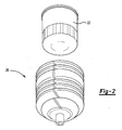
Figure 2 shows the relationship between a filter and the tool. (Not sureFigure 2 is required.) -
Figure 3 is a cross-sectional view through a second tool embodiment. -
Figure 4 is a cross-sectional view through another tool embodiment. - An
oil removal tool 20 is illustrated inFigure 1A . As shown, anoil filter 22 is typically secured to a vehicle engine. A holding anddrive structure 26 within abellows 28 is relatively rigid, and is sized to receive a bottom peripheral surface of theoil filter 22. Anupper end 30 of the bellows surrounds an upper end of theoil filter 22 adjacent to the oil seal surface, and provides areservoir 32 to capture leakage oil asoil filter 22 is removed. A drive is provided, such as a standardsquare drive 36, and allows thesocket 26 andbellows 28 to be turned. The standard square drive may be formed integrally with a portion of the tool, or may be welded, or otherwise attached to the tool. The standard square drive receives the tool internally to turn the tool and the filter, or may include an external hex to allow a wrench to drive the tool. As thebellows 28 turns, thestructure 26 simultaneously turns thefilter 22, and the filter is removed from thevehicle frame 24. The bellows is spring loaded against the mating seal surface through its own natural spring rate. As thefilter 22 comes away from thevehicle frame 24, the upper surface of the bellows remains in contact with the vehicle frame, thus, leakage oil will be captured within thereservoir 32. As can be appreciated, the bellows is resilient and allows the tool to conform to frame 24 to reliably capture the oil and to accommodatefilters 22 of various lengths. - As shown, a filter port 33 may be positioned on the
vehicle frame 24 to receive a filter and gasket 31. As can be appreciated fromFigure 2 , thestructure 26 will capture and tightly hold thefilter 22. -
Figure 1B is an exploded view showing thefilter 22 removed from thebellows 28. Abolt 100 captures aplate 102 with thenut 34, and assorted sealing washers, etc. The socket is permanently attached to provide a sealed square drive. -
Figure 1C shows anembodiment 100 wherein abase 102 is welded to adrive 104, or may be formed as a one-piece glass reinforced injection molded part with or without insert structure as deemed appropriate. Thebellows 106 may be bonded or integrally molded to thebase 102. Abond 108 is utilized at the intersection of 102 and 106, providing a seal and mechanical retention. This may also be a tight snap fit. - Figure ID shows an
embodiment 150, whereinrivets 158 secure theseveral layers drive 156 is secured to thelayer 154 in some manner. - In sum, any method of attaching a leak free drive to the member may be utilized, and various types of drives may be utilized.
-
Figure 3 shows anotherembodiment 50, wherein adrive tool 52 at the bottom of thebellows 28 has astandard drive structure 53 that serves to move onto mating structure on the oil filter (removed for clarity), and drive the oil filter for removal. Again, a leakfree reservoir 170 is provided by thebellows 28. The choice of thedrive surface 26 or thedrive tool 52 for driving the filter will be dependent upon the type of filter, thus providing more options. Seals such as o rings at the base of this assembly allowdrive tool 52 to be axially positioned as required for filter height differences while providing a leak free seal at the base of this assembly. -
Figure 4 shows anotherembodiment 70. Inembodiment 70, astrap wrench filter 22. A snug fit, slip-oncup 76 has a radially outwardly extendinglip 78 providing the reservoir 80. Again, as thefilter 22 is removed, leakage oil will be captured in the reservoir 80. A reinforcement such as a spring orresilient strap 160 may serve to hold thecup 76 on thefilter 22. Thecup 76 may be a snug fit, but still able to slide and flex along the filter. While astrap wrench 74 is shown inFigure 4 , a socket drive, or other type of drive may be utilized. - In the embodiments utilizing bellows, of course the number and shape of the bellows may vary.
- Although embodiments of this invention have been disclosed, a worker of ordinary skill in this art would recognize that certain modifications would come within the scope of this invention. For that reason, the following claims should be studied to determine the true scope and content of this invention.
Claims (11)
- An oil filter removal tool (20; 100; 150; 170; 70) comprising;
a member (28; 106; 76) having an upper surface to be spaced away from a radially outer surface of an oil filter (22), said member defining a reservoir (32; 170; 80) for capturing leakage oil as the oil filter is removed. - The oil filter removal tool as set forth in claim 1, wherein said member surface is an upper surface which is spaced slightly away from said outer surface.
- A method of oil filter removal comprising;
providing a member (28; 106; 70) having a surface to be spaced away from a radially outer surface of an oil filter (22), and said member (28; 106; 76) defining a reservoir (32; 170; 80) for capturing leakage oil as the oil filter (22) is removed, and removing the oil filter (22) and capturing leaking oil in the reservoir (32; 170; 80). - The method as set forth in claim 3 wherein said member surface is an upper surface which is spaced slightly away from said outer surface.
- The tool or method as set forth in any preceding claim, wherein the member (28; 106; 76) is utilized in combination with a tool for turning the oil filter (22) for removal.
- The tool or method as set forth in claim 5, wherein the tool is attached to the member (28; 106).
- The tool or method as set forth in claim 5, wherein the tool that is used is a tool separate from the member (76).
- The tool or method as set forth in claim 5, wherein the tool is a drive strap (74).
- The tool or method as set forth in claim 5, wherein the tool (26; 52) for turning the filter (22) includes an inner surface in the member, which closely surrounds a surface of the filter (22) to provide friction to the filter as the member is turned.
- The tool or method as set forth in claim 5, wherein the tool for turning the filter includes a nut (34) at a bottom of the member (28).
- The tool or method as set forth in any preceding claim, wherein the member (28; 106) is bellows shaped.
Applications Claiming Priority (1)
| Application Number | Priority Date | Filing Date | Title |
|---|---|---|---|
| US11/746,763 US20080276763A1 (en) | 2007-05-10 | 2007-05-10 | No mess oil filter removal tool |
Publications (1)
| Publication Number | Publication Date |
|---|---|
| EP1990136A1 true EP1990136A1 (en) | 2008-11-12 |
Family
ID=39673523
Family Applications (1)
| Application Number | Title | Priority Date | Filing Date |
|---|---|---|---|
| EP08251604A Withdrawn EP1990136A1 (en) | 2007-05-10 | 2008-05-02 | Oil filter removal tool |
Country Status (2)
| Country | Link |
|---|---|
| US (1) | US20080276763A1 (en) |
| EP (1) | EP1990136A1 (en) |
Cited By (2)
| Publication number | Priority date | Publication date | Assignee | Title |
|---|---|---|---|---|
| WO2011041018A3 (en) * | 2009-10-02 | 2011-06-03 | Strategic Tools & Equipment Company | Oil filter removal tool with integral oil retaining reservoir |
| US10065298B1 (en) | 2016-11-08 | 2018-09-04 | Richard Winscott | Oil filter removal tool |
Families Citing this family (9)
| Publication number | Priority date | Publication date | Assignee | Title |
|---|---|---|---|---|
| USD772662S1 (en) | 2015-04-16 | 2016-11-29 | Thomas L. Klamm | Oil filter removal tool |
| US20160325417A1 (en) * | 2015-04-16 | 2016-11-10 | Thomas L. Klamm | Oil filter removal tool |
| US20160303719A1 (en) * | 2015-04-16 | 2016-10-20 | Thomas L. Klamm | Oil filter removal tool |
| US10350738B2 (en) | 2016-07-07 | 2019-07-16 | Michael H. Sapp | Oil filter tool |
| US10518394B2 (en) | 2018-01-08 | 2019-12-31 | Robert Paul Quick | Fluid filter removal device and method of use |
| US11154968B2 (en) | 2019-10-11 | 2021-10-26 | Kevin Francis Moran | Oil filter removal device |
| USD912714S1 (en) * | 2019-10-11 | 2021-03-09 | Kevin Francis Moran | Oil filter removal device |
| USD912713S1 (en) * | 2019-10-11 | 2021-03-09 | Kevin Francis Moran | Oil filter removal device |
| US11492195B2 (en) | 2020-02-28 | 2022-11-08 | Cap Shafer | Disposable sheath for oil filter removal and containment |
Citations (8)
| Publication number | Priority date | Publication date | Assignee | Title |
|---|---|---|---|---|
| US4266452A (en) * | 1980-01-14 | 1981-05-12 | Crist Robert M | Oil filter wrench |
| US5271299A (en) * | 1993-03-18 | 1993-12-21 | Jake Wadsworth | Oil filter wrench with oil catching boot |
| US5924342A (en) * | 1997-05-15 | 1999-07-20 | Chou; Joseph M. | Oil filter wrench |
| US6401574B1 (en) * | 2000-08-10 | 2002-06-11 | Jacob L. Myers | Oil filter removal and installation device |
| US20030062221A1 (en) * | 2001-10-01 | 2003-04-03 | Burrow Thomas Marvin | Oil filter containment receptacle |
| US20060053983A1 (en) * | 2004-09-13 | 2006-03-16 | Groetsch Charles A | Oil filter canister tool |
| US20060112792A1 (en) * | 2004-11-29 | 2006-06-01 | Great Neck Saw Manufacturers, Inc. | Strap wrench |
| US7156067B1 (en) * | 2005-04-14 | 2007-01-02 | Gottschalk Kent J | Apparatus and method for conducting oil within a motorcycle frame space |
Family Cites Families (16)
| Publication number | Priority date | Publication date | Assignee | Title |
|---|---|---|---|---|
| US4020922A (en) * | 1976-01-08 | 1977-05-03 | Klasel Dan E | Filter catcher |
| US4643053A (en) * | 1981-09-09 | 1987-02-17 | Rhodes Charles W | Oil filter removal tool |
| US4376703A (en) * | 1981-11-10 | 1983-03-15 | Leonard Krauss | Oil filter cover |
| US4451368A (en) * | 1982-09-30 | 1984-05-29 | Pandelena Michael N | Annular drip collector and cap |
| US4865727A (en) * | 1986-12-16 | 1989-09-12 | Leonard Krauss | New and used oil filter container with used filter removing means |
| JPS63242586A (en) * | 1987-03-30 | 1988-10-07 | Canon Inc | Recording material |
| US4822386A (en) * | 1987-11-27 | 1989-04-18 | United Technologies Corporation | Filter replacement mechanism |
| US4841628A (en) * | 1987-12-21 | 1989-06-27 | United Technologies Corporation | Filter replacement mechanism |
| US5035811A (en) * | 1989-09-21 | 1991-07-30 | United Technologies Corporation | Filter pump system |
| FR2659453B1 (en) * | 1990-03-12 | 1992-05-15 | Commissariat Energie Atomique | DEVICE FOR VIEWING POSITION DESINTEGRATIONS. |
| US5207131A (en) * | 1991-04-25 | 1993-05-04 | Lisle Corporation | Oil filter removal tool |
| US5154102A (en) * | 1991-07-25 | 1992-10-13 | Becker Jerome C | Oil filter removal tool |
| US5379330A (en) * | 1993-10-12 | 1995-01-03 | General Electric Company | Inner filter removal tool |
| US5347554A (en) * | 1993-10-12 | 1994-09-13 | General Electric Company | Outer filter removal tool |
| US5469935A (en) * | 1994-09-01 | 1995-11-28 | Hewuse; Monte P. | Oil filter removal aid |
| US5845552A (en) * | 1997-02-28 | 1998-12-08 | Piascik; Jerome Paul Phillip | Tool and method for removal of an oil filter cartridge cap from marine and automotive engines |
-
2007
- 2007-05-10 US US11/746,763 patent/US20080276763A1/en not_active Abandoned
-
2008
- 2008-05-02 EP EP08251604A patent/EP1990136A1/en not_active Withdrawn
Patent Citations (8)
| Publication number | Priority date | Publication date | Assignee | Title |
|---|---|---|---|---|
| US4266452A (en) * | 1980-01-14 | 1981-05-12 | Crist Robert M | Oil filter wrench |
| US5271299A (en) * | 1993-03-18 | 1993-12-21 | Jake Wadsworth | Oil filter wrench with oil catching boot |
| US5924342A (en) * | 1997-05-15 | 1999-07-20 | Chou; Joseph M. | Oil filter wrench |
| US6401574B1 (en) * | 2000-08-10 | 2002-06-11 | Jacob L. Myers | Oil filter removal and installation device |
| US20030062221A1 (en) * | 2001-10-01 | 2003-04-03 | Burrow Thomas Marvin | Oil filter containment receptacle |
| US20060053983A1 (en) * | 2004-09-13 | 2006-03-16 | Groetsch Charles A | Oil filter canister tool |
| US20060112792A1 (en) * | 2004-11-29 | 2006-06-01 | Great Neck Saw Manufacturers, Inc. | Strap wrench |
| US7156067B1 (en) * | 2005-04-14 | 2007-01-02 | Gottschalk Kent J | Apparatus and method for conducting oil within a motorcycle frame space |
Cited By (2)
| Publication number | Priority date | Publication date | Assignee | Title |
|---|---|---|---|---|
| WO2011041018A3 (en) * | 2009-10-02 | 2011-06-03 | Strategic Tools & Equipment Company | Oil filter removal tool with integral oil retaining reservoir |
| US10065298B1 (en) | 2016-11-08 | 2018-09-04 | Richard Winscott | Oil filter removal tool |
Also Published As
| Publication number | Publication date |
|---|---|
| US20080276763A1 (en) | 2008-11-13 |
Similar Documents
| Publication | Publication Date | Title |
|---|---|---|
| EP1990136A1 (en) | Oil filter removal tool | |
| CN100364636C (en) | Mounts for combustion engine filter cartridges | |
| US20070158917A1 (en) | Seal Assembly with Protective Filter | |
| JP2005270964A (en) | Spin-on filter with performance enhancement features | |
| CN111148889B (en) | Sealing device, kit of parts and method | |
| CN1919407A (en) | Container having a detachable lid | |
| CN1990079A (en) | Fluid filter and method of using same | |
| KR20190008330A (en) | Especially compressed air preparation systems for compressed air preparation units of commercial vehicles | |
| CN107921335A (en) | Filter cell with end cap seal | |
| JP2009150330A (en) | Oil filter | |
| US9810184B2 (en) | Air filter device, especially for a motor vehicle | |
| JP4831055B2 (en) | Drain mechanism of fluid filter | |
| JP4877618B2 (en) | Breeza | |
| US20120012587A1 (en) | Liquid tank for working machine engine and liquid tank cap | |
| CN115516233B (en) | Sealing assembly having a sealing unit | |
| JP2010242872A (en) | Breeza | |
| CN114608225A (en) | Closing plug for a collector of a refrigerant circuit | |
| US20060242934A1 (en) | Air filter assembly | |
| US20090001010A1 (en) | Oil Filter Device for an Internal Combustion Engine | |
| JP2010149006A (en) | Oil filter | |
| JPH07158564A (en) | Seal cap of compressor | |
| EP1430941A1 (en) | Fluid filter, drain mechanism thereof and draining method of fluid filter | |
| JP2008185094A (en) | Breather device for transmission | |
| KR200407164Y1 (en) | Oil Filter Remover Leak Oil Collection Tool | |
| JP6900803B2 (en) | Liquid drainage aid |
Legal Events
| Date | Code | Title | Description |
|---|---|---|---|
| PUAI | Public reference made under article 153(3) epc to a published international application that has entered the european phase |
Free format text: ORIGINAL CODE: 0009012 |
|
| AK | Designated contracting states |
Kind code of ref document: A1 Designated state(s): AT BE BG CH CY CZ DE DK EE ES FI FR GB GR HR HU IE IS IT LI LT LU LV MC MT NL NO PL PT RO SE SI SK TR |
|
| AX | Request for extension of the european patent |
Extension state: AL BA MK RS |
|
| AKX | Designation fees paid | ||
| REG | Reference to a national code |
Ref country code: DE Ref legal event code: 8566 |
|
| STAA | Information on the status of an ep patent application or granted ep patent |
Free format text: STATUS: THE APPLICATION IS DEEMED TO BE WITHDRAWN |
|
| 18D | Application deemed to be withdrawn |
Effective date: 20090513 |