EP1989451B1 - A fastener provided with a snap-engagement foot for thrusting through a hole in a panel - Google Patents
A fastener provided with a snap-engagement foot for thrusting through a hole in a panel Download PDFInfo
- Publication number
- EP1989451B1 EP1989451B1 EP06842285A EP06842285A EP1989451B1 EP 1989451 B1 EP1989451 B1 EP 1989451B1 EP 06842285 A EP06842285 A EP 06842285A EP 06842285 A EP06842285 A EP 06842285A EP 1989451 B1 EP1989451 B1 EP 1989451B1
- Authority
- EP
- European Patent Office
- Prior art keywords
- wing
- foot
- edge surface
- situated
- shoulder
- Prior art date
- Legal status (The legal status is an assumption and is not a legal conclusion. Google has not performed a legal analysis and makes no representation as to the accuracy of the status listed.)
- Expired - Fee Related
Links
- 230000005489 elastic deformation Effects 0.000 claims description 4
- 230000000694 effects Effects 0.000 description 10
- 230000000284 resting effect Effects 0.000 description 7
- 238000000605 extraction Methods 0.000 description 5
- 230000037431 insertion Effects 0.000 description 2
- 238000003780 insertion Methods 0.000 description 2
- 238000004519 manufacturing process Methods 0.000 description 2
- 238000009966 trimming Methods 0.000 description 2
- 239000000463 material Substances 0.000 description 1
- 239000002184 metal Substances 0.000 description 1
- 229920003023 plastic Polymers 0.000 description 1
- 239000004033 plastic Substances 0.000 description 1
- 230000000750 progressive effect Effects 0.000 description 1
- 230000000717 retained effect Effects 0.000 description 1
- 238000000926 separation method Methods 0.000 description 1
- 239000007787 solid Substances 0.000 description 1
Images


Classifications
-
- F—MECHANICAL ENGINEERING; LIGHTING; HEATING; WEAPONS; BLASTING
- F16—ENGINEERING ELEMENTS AND UNITS; GENERAL MEASURES FOR PRODUCING AND MAINTAINING EFFECTIVE FUNCTIONING OF MACHINES OR INSTALLATIONS; THERMAL INSULATION IN GENERAL
- F16B—DEVICES FOR FASTENING OR SECURING CONSTRUCTIONAL ELEMENTS OR MACHINE PARTS TOGETHER, e.g. NAILS, BOLTS, CIRCLIPS, CLAMPS, CLIPS OR WEDGES; JOINTS OR JOINTING
- F16B21/00—Means for preventing relative axial movement of a pin, spigot, shaft or the like and a member surrounding it; Stud-and-socket releasable fastenings
- F16B21/06—Releasable fastening devices with snap-action
- F16B21/08—Releasable fastening devices with snap-action in which the stud, pin, or spigot has a resilient part
- F16B21/086—Releasable fastening devices with snap-action in which the stud, pin, or spigot has a resilient part the shank of the stud, pin or spigot having elevations, ribs, fins or prongs intended for deformation or tilting predominantly in a direction perpendicular to the direction of insertion
-
- F—MECHANICAL ENGINEERING; LIGHTING; HEATING; WEAPONS; BLASTING
- F16—ENGINEERING ELEMENTS AND UNITS; GENERAL MEASURES FOR PRODUCING AND MAINTAINING EFFECTIVE FUNCTIONING OF MACHINES OR INSTALLATIONS; THERMAL INSULATION IN GENERAL
- F16B—DEVICES FOR FASTENING OR SECURING CONSTRUCTIONAL ELEMENTS OR MACHINE PARTS TOGETHER, e.g. NAILS, BOLTS, CIRCLIPS, CLAMPS, CLIPS OR WEDGES; JOINTS OR JOINTING
- F16B5/00—Joining sheets or plates, e.g. panels, to one another or to strips or bars parallel to them
- F16B5/06—Joining sheets or plates, e.g. panels, to one another or to strips or bars parallel to them by means of clamps or clips
-
- F—MECHANICAL ENGINEERING; LIGHTING; HEATING; WEAPONS; BLASTING
- F16—ENGINEERING ELEMENTS AND UNITS; GENERAL MEASURES FOR PRODUCING AND MAINTAINING EFFECTIVE FUNCTIONING OF MACHINES OR INSTALLATIONS; THERMAL INSULATION IN GENERAL
- F16B—DEVICES FOR FASTENING OR SECURING CONSTRUCTIONAL ELEMENTS OR MACHINE PARTS TOGETHER, e.g. NAILS, BOLTS, CIRCLIPS, CLAMPS, CLIPS OR WEDGES; JOINTS OR JOINTING
- F16B5/00—Joining sheets or plates, e.g. panels, to one another or to strips or bars parallel to them
- F16B5/06—Joining sheets or plates, e.g. panels, to one another or to strips or bars parallel to them by means of clamps or clips
- F16B5/0607—Joining sheets or plates, e.g. panels, to one another or to strips or bars parallel to them by means of clamps or clips joining sheets or plates to each other
- F16B5/0621—Joining sheets or plates, e.g. panels, to one another or to strips or bars parallel to them by means of clamps or clips joining sheets or plates to each other in parallel relationship
- F16B5/065—Joining sheets or plates, e.g. panels, to one another or to strips or bars parallel to them by means of clamps or clips joining sheets or plates to each other in parallel relationship the plates being one on top of the other and distanced from each other, e.g. by using protrusions to keep contact and distance
Definitions
- the invention generally concerns fasteners for fixing a member to a panel such as a car body sheet metal panel
- Such a fastener is known in particular from the document FR 2 789 454 A which is provided with a head and a snap-engagement foot comprising a flat rigid core and two curved flexible wings.
- This rigid core has two longitudinal edge surfaces converging towards a pointed end while, by its other end, it is connected to the rest of the fastener.
- Each wing is connected to that core along one of the two longitudinal edge surfaces of the core and has, facing a respective planar face of the core, an inner surface bordered by that planar face, by a longitudinal edge surface of that wing and by a transverse edge surface of that wing.
- the outer surface of the foot tapers respectively towards the free end and towards the transverse edge surface of the wings, on each side of an inflection plane that is transversely oriented to the axial direction of the foot.
- This outer surface of the foot has, at the inflection plane, a generally oval shape of which the small width is locate along the median axial plane of the core and of which the large width is located along the axial plane transversely oriented to the median axial plane of the core.
- each wing is adapted to flex by elastic deformation towards the planar face of the core which faces its inner surface.
- each wing is concave and the longitudinal edge surface of each wing has, viewed by an observer situated parallel to the planar face of the core which faces its inner surface, a V-shape of which the point, which is directed outwardly, is located at the inflection plane on each side of which the outer surface of the foot tapers.
- the invention is directed to providing a fastener of the same type but with improved performance in terms of resistance to the extraction forces exerted on it, while being particularly simple and convenient to manufacture and to use.
- the invention provides a fastener provided with a head and a snap-engagement foot for thrusting through a hole in a panel, said foot comprising a rigid core, which extends from said head, and curved flexible wings, each said wing having a convex surface bordered by said core, by a longitudinal edge surface and by a transverse edge surface facing said head, said foot tapering respectively towards the free end of said core and towards said transverse edge surfaces on each side of an inflection plane that is transversely oriented to said core, characterized in that each said longitudinal edge surface has, viewed by an observer viewing said convex surface, a V-shape of which the point, which is directed outwardly, is located at said inflection plane, said core being a hub about which at least three said wings are regularly spaced, each said wing comprising a corner delimited by said longitudinal edge surface on each side of said inflection plane and by a shoulder, said shoulder and the surface of the corner situated between said longitudinal edge surface and said shoulder being on the opposite
- the effect of the cooperation between the outline of the hole and the wings is that by elastic deformation each wing, while it is in contact with the outline of the hole, flexes, in its introductory part that is situated between the pointed end and the inflection plane, towards the convex surface of the neighboring wing.
- the wings thus flex progressively with insertion until the point at which the introductory part of the wings has passed though the hole.
- Each of the wings relaxes, the effect of the cooperation between the outline of the hole and the corners, in the retaining part situated between the inflection plane and the transverse edge surface, being to drive the foot in the direction of insertion until the rest of the fastener abuts the surface of the panel situated at the side from which the fastener is introduced, by means of a frusto-conical fluid-tight collar.
- the fastener may be subject to extraction forces not strictly oriented in the axial direction. As each wing is in contact with the outline of the hole, when the fastener is subject to such a force, several neighboring wings may deform and contribute to resisting that force.
- the fastener 1 is of plastics material molded as a single piece. It comprises a head 2 and a snap-engagement foot 3.
- the snap-engagement foot 3 comprises a hub 4 and six identical wings 5 to 10.
- the hub 4 extends transversely to the head 2.
- the hub 4 is cylindrical and has an axis A which is more generally the main axis of the fastener 1.
- the hub 4 is connected at one of its ends to the head 2 whereas its other end 11 is free.
- the wings 5 to 10 are connected to the hub 4 and are regularly distributed around the hub, with an angular spacing of 60° between two successive wings.
- the wing 5 will now be described. The following description of the wing 5 also applies to the wings 6 to 10, the six wings 5 to 10 being identical.
- the wing 5 comprises a web 12 and a corner 13.
- the web 12 is connected to the hub 4 and the corner 13 is connected to the web 12.
- the web 12 is a thin cylindrical wall portion; the corner 13 is a solid, thicker portion.
- the corner 13 is rigid overall whereas the web 12 is more pliable and is adapted to flex.
- the wing 5 has a resting position when subject to no external biasing.
- the snap-engagement foot 3 is adapted to be thrust into a hole, when the wing 5 enters into contact with the outline of a hole and the outline of the hole bears on wing 5, the web 12 flexes and the corner 13 moves towards the web 12 of the neighboring wing 6.
- the wing 5 is bordered by the hub 4, by an outwardly oriented longitudinal edge surface 16 and by a transverse edge surface 17 facing the head 2.
- the wing 5 has two main surfaces, a convex surface 15 of which the cross-section transverse to the axial direction of the foot 3 has the general form of an arc of a circle and a surface 20 on the opposite side from the convex surface 15.
- the surface 20 comprises a surface portion 21 which belongs to the web 12. This surface portion 21 is concave and has a profile corresponding to that of the surface 15.
- Surface 20 also comprises a rectilinear shoulder 22, connected to the surface 21 and generally oriented transversely to that surface 21.
- the surface 20 also comprises a surface portion 23 connected to the shoulder 22 and bordered by the longitudinal edge surface 16.
- the wing 5 comprises an introductory portion situated between the free end 11 and an inflection plane 25 transverse to the hub 4, and a retaining part situated between the inflection plane 25 and the transverse edge surface 17.
- the longitudinal edge surface 16 comprises a first branch 30 extending between the free end 11 and the inflection plane 25 and a second branch 31 extending between the inflection plane 25 and the transverse edge surface 17.
- the branch 31 is shorter than the branch 30.
- these two branches 30, 31 are wider. They have a convergent outline and a pointed end 32.
- the ends 32 of the branches 30, 31 are each located in the inflection plane 25.
- the longitudinal edge surface 16 has a V-shape of which the point is outwardly oriented and is situated in the inflection plane 25 such that the wing 5 has a vertex 36 situated in that inflection plane 25.
- the ends of the surfaces 15, 20 away from the hub 4 are pointed, and are situated in the plane 25. Moreover, the surfaces 15, 20 and the branches 30, 31 meet at the vertex 36 of the wing 5.
- the branch 30 has a portion 33 belong to the web 12 and a portion 34 belonging to the corner 13.
- the portion 33 which is rounded and which belongs to the web 12, is thin with respect to the width of the portion 34.
- the portion 34 belonging to the corner 13 comprises a thin zone 35 of junction with the surface 15.
- the zone 35 is rounded and extends on a locus continuous with the portion 33 and between that portion 33 and the vertex 36.
- the transverse edge surface 17 which belongs to the web 12 is situated adjacent the end where the head 2 is located.
- the cross-section of the foot 3 has a generally circular outline of which the diameter increases on going towards the plane 25.
- the head 2 comprises a flange 40, a shank 41, a plate 42 and a fluid-tight collar 43, these different members being coaxial and each having a generally circular form.
- a trimming piece 45 Figure 11
- a car body side embellishment having an opening in the form of a keyhole of which the round part is of a diameter corresponding to that of the flange 40 and of which the elongate portion is of width corresponding to that of the shank 41.
- the wall thickness of the member 45 in which the keyhole opening is made corresponds to the separation between the flange 40 and the plate 42, the mounting of the member 45 being achieved by pushing the flange 40 through the round part of the keyhole opening then by sliding the member 45 parallel to the orientation of the elongate portion of the keyhole opening, such that the shank 41 engages in that elongate portion.
- the fluid-tight collar 43 conventionally has a frusto-conical shape, but is of particularly small thickness.
- the plate 42 consequently comprises an extension outwardly beyond its connection with the collar 43, making it possible to avoid continuation of the pushing of the head 2 into the round part of the keyhole opening beyond the plate 42 (if the wall of the member 45 were to abut directly against the collar 43, the flexibility thereof would mean that the collar 43 could pass through the round part of the keyhole opening).
- the collar 43 is connected to the hub 4 by a shank 48.
- the shank 48 is cylindrical whereas at the junction with the collar 43, the shank 48 is flares slightly outwardly as far as a common intersection line 49 with the surface of the collar 43 facing the foot 3.
- the panel 46 to which it is intended to fix the fastener 1 ( Figure 11 ) has a hole 47 of circular outline of specific diameter.
- the foot 3 is provided to be thrust into the hole 47, the end 11 first, the contact of the foot 3 with the outline of the hole 47 occurring via the portions 34 of the longitudinal edge surfaces 16.
- the portions 33 then 34 of the branches 30 come into contact with the outline of the hole 47.
- the webs 12 act as a hinge enabling the progressive flexing of each wing 5 to 10 towards the convex surface 15 of the neighboring wing. This flexing makes the circumference of the hole 47 coincide with that of the foot 3 at the level of that hole 47 such that the foot 3 can be further pushed in until the level of the inflection plane 25 is reached.
- the wings 5 to 10 will undergo elastic relaxation that is to say that they will start to extend to resume their resting position, the effect of which will be to move the foot 3 in the direction opposite to the pushing in.
- the level of the foot 3 corresponding to the inflection plane 25 is passed, by continuing the pushing in, it is the branches 31 that come into contact with the outline of the hole 47.
- the outer surface of the foot 3 tapers towards the transverse edge surfaces 17 such that the more the foot 3 is pushed in, the more the wings 5 to 10 can extend towards their resting position.
- Pushing in is continued until abutment occurs on the face of the panel 46 situated on the side from which the pushing in of the foot 3 has been carried out where the fluid-tight collar 43 is applied against the panel 46.
- the branches 31 are in contact with the outline of the hole 47 and the wings 5 to 10 all flex in the same direction around the hub 4.
- the foot 3 is pulled out of the hole 47 until the level of the inflection plane 25 is reached.
- the wings 5 to 10 can progressively resume their resting position due to the outer surface of the foot 3 tapering towards the free end 11.
- the difference in slope of the branches 30 and 31 contributes to enabling the foot to be pushed in with a relatively moderate force whereas the retaining force in the hole 47 is relatively high.
- the member 45 and the panel 46 may be caused to move with respect to each other. These movements may create forces in the direction of extraction of the fastener 1 while having a transverse component acting on the foot 3. When the extraction is not carried out along the axis of the foot 3, forces having such a component also exist.
- the force may be taken up by deformation of several of the wings 5 to 10.
- the web 112 is of greater thickness adjacent the transverse edge surface (which corresponds to the transverse edge surface 17 of the embodiment represented in Figures 1 to 9 and 11 ) than adjacent the free end (which corresponds to the free end 11 of the embodiment represented in Figures 1 to 9 and 11 ), and more particularly the thickness increases regularly towards the transverse edge surface.
- the greater thickness of the web 112 adjacent the transverse edge surface makes the flexing of the web 112 more difficult there than adjacent the free end.
- This difference in thickness in addition to the effect of the difference in slope of the branches, contributes to enabling the foot to be pushed in with a relatively moderate force whereas the retaining force is relatively high.
- the web has a first thickness adjacent the transverse edge surface, and a second thickness adjacent the free end.
- the two thicknesses are different and the web has a transverse shoulder at a specific distance from the transverse edge surface.
- the fastener comprises a number of wings different from six, and at least equal to three, for example five or seven wings regularly distributed around the hub.
- the head is overmolded onto the foot.
- the head 2 which may for example be replaced by a head serving to fix cables or tubes rather than a trimming piece having a keyhole opening.
Description
- The invention generally concerns fasteners for fixing a member to a panel such as a car body sheet metal panel
- It is known that such fasteners exist which, for them to be fixed, are provided with a snap-engagement foot for thrusting through a hole of predetermined diameter in the panel.
- Such a fastener is known in particular from the
document FR 2 789 454 A - Such a fastener is greatly appreciated since it makes it possible to minimize the force required to introduce the foot into the hole and to maximize the retaining force given by the snap-engagement foot to prevent extraction of the fastener.
- The invention is directed to providing a fastener of the same type but with improved performance in terms of resistance to the extraction forces exerted on it, while being particularly simple and convenient to manufacture and to use.
- To that end, the invention provides a fastener provided with a head and a snap-engagement foot for thrusting through a hole in a panel, said foot comprising a rigid core, which extends from said head, and curved flexible wings, each said wing having a convex surface bordered by said core, by a longitudinal edge surface and by a transverse edge surface facing said head, said foot tapering respectively towards the free end of said core and towards said transverse edge surfaces on each side of an inflection plane that is transversely oriented to said core, characterized in that each said longitudinal edge surface has, viewed by an observer viewing said convex surface, a V-shape of which the point, which is directed outwardly, is located at said inflection plane, said core being a hub about which at least three said wings are regularly spaced, each said wing comprising a corner delimited by said longitudinal edge surface on each side of said inflection plane and by a shoulder, said shoulder and the surface of the corner situated between said longitudinal edge surface and said shoulder being on the opposite side from said convex surface, each said wing also comprising a web less thick than said corner, disposed between said hub and said shoulder, each said wing being adapted, in order to allow the snap engagement of said foot in said hole, to flex by elastic deformation towards the convex surface of the neighboring wing situated on the same side as said shoulder.
- On thrusting the snap-engagement foot into the hole in the panel, the effect of the cooperation between the outline of the hole and the wings is that by elastic deformation each wing, while it is in contact with the outline of the hole, flexes, in its introductory part that is situated between the pointed end and the inflection plane, towards the convex surface of the neighboring wing. The wings thus flex progressively with insertion until the point at which the introductory part of the wings has passed though the hole. Each of the wings then relaxes, the effect of the cooperation between the outline of the hole and the corners, in the retaining part situated between the inflection plane and the transverse edge surface, being to drive the foot in the direction of insertion until the rest of the fastener abuts the surface of the panel situated at the side from which the fastener is introduced, by means of a frusto-conical fluid-tight collar.
- Once mounted, on relative movement between the member to fix and the panel or on dismantling, the fastener may be subject to extraction forces not strictly oriented in the axial direction. As each wing is in contact with the outline of the hole, when the fastener is subject to such a force, several neighboring wings may deform and contribute to resisting that force.
- It will be noted that in the above-mentioned prior fastener, the outline of the hole is in contact with the edge surfaces of the rigid core and with the outer surface of each wing. That fastener gives very high resistance to forces oriented in the plane of the rigid core. On the other hand, forces which are not oriented in that plane meet less resistance since that resistance is only provided by a single wing.
- According to features of implementation that are particularly simple and convenient both with respect to manufacture and use:
- said longitudinal edge surface comprises on each side of said inflection plane a branch having, on said corner, a convergent outline and a pointed end at said inflection plane; and possibly
- said branch situated in the introductory part that is situated between said free end and said inflection plane, comprises a first branch portion belonging to said web and a second branch portion belonging to said corner which has a junction zone with said convex surface, said junction zone being situated on a locus continuous with said first branch portion; and/or
- for each said wing, said transverse edge surface extends between said hub and said shoulder, facing said head; and/or
- said longitudinal edge surface comprises in the introductory part of each said wing, situated between said free end and said inflection plane, a branch that is longer than the branch situated in the retaining part of that wing, situated between said inflection plane and said transverse edge surface of that wing; and/or
- said shoulder is rectilinear; and/or
- said web is of constant thickness; or
- said web has a greater thickness towards said transverse edge surface than towards said free end; and/or
- said wings are each of the same form; and/or
- said fastener comprises six said wings.
- The features and advantages of the invention will appear from the following description, given by way of preferred but non-limiting example, with reference to the accompanying drawings in which:
-
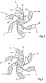
Figure 1 is a view in elevation of a fastener according to the present invention; -
Figure 2 is a plan view of that fastener from below; -
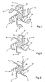
Figures 3 to 9 are cross-section views of the foot of that fastener taken on the respective planes III-III to IX-IX identified inFigure 1 , the fluid-tight collar not being represented; -
Figure 10 is a plan view of the panel on which the illustrated fastener is to be fixed, showing the neighborhood of the hole where the snap-engagement foot is to be introduced; -
Figure 11 is a view in elevation of that fastener in place in a member to be fixed and snap engaged onto a panel, the member and the panel being represented in cross-section; and -
Figures 12 and 13 are cross-section views of the foot of a fastener according to a variant embodiment, similar to those ofFigures 4 and7 and taken on two respective planes situated at the same level as planes IV - IV and VII - VII identified inFigure 1 . - The fastener 1 is of plastics material molded as a single piece. It comprises a
head 2 and a snap-engagement foot 3. - The snap-
engagement foot 3 comprises ahub 4 and sixidentical wings 5 to 10. - The
hub 4 extends transversely to thehead 2. Thehub 4 is cylindrical and has an axis A which is more generally the main axis of the fastener 1. Thehub 4 is connected at one of its ends to thehead 2 whereas itsother end 11 is free. - The
wings 5 to 10 are connected to thehub 4 and are regularly distributed around the hub, with an angular spacing of 60° between two successive wings. - The
wing 5 will now be described. The following description of thewing 5 also applies to thewings 6 to 10, the sixwings 5 to 10 being identical. - The
wing 5 comprises aweb 12 and acorner 13. Theweb 12 is connected to thehub 4 and thecorner 13 is connected to theweb 12. - The
web 12 is a thin cylindrical wall portion; thecorner 13 is a solid, thicker portion. Thecorner 13 is rigid overall whereas theweb 12 is more pliable and is adapted to flex. - The
wing 5 has a resting position when subject to no external biasing. - Because the snap-
engagement foot 3 is adapted to be thrust into a hole, when thewing 5 enters into contact with the outline of a hole and the outline of the hole bears onwing 5, theweb 12 flexes and thecorner 13 moves towards theweb 12 of the neighboringwing 6. - The
wing 5 is bordered by thehub 4, by an outwardly orientedlongitudinal edge surface 16 and by a transverse edge surface 17 facing thehead 2. - The
wing 5 has two main surfaces, aconvex surface 15 of which the cross-section transverse to the axial direction of thefoot 3 has the general form of an arc of a circle and asurface 20 on the opposite side from theconvex surface 15. Thesurface 20 comprises asurface portion 21 which belongs to theweb 12. Thissurface portion 21 is concave and has a profile corresponding to that of thesurface 15.Surface 20 also comprises arectilinear shoulder 22, connected to thesurface 21 and generally oriented transversely to thatsurface 21. Thesurface 20 also comprises asurface portion 23 connected to theshoulder 22 and bordered by thelongitudinal edge surface 16. - In the axial direction of the
foot 3, thewing 5 comprises an introductory portion situated between thefree end 11 and aninflection plane 25 transverse to thehub 4, and a retaining part situated between theinflection plane 25 and the transverse edge surface 17. - The
longitudinal edge surface 16 comprises afirst branch 30 extending between thefree end 11 and theinflection plane 25 and asecond branch 31 extending between theinflection plane 25 and the transverse edge surface 17. Thebranch 31 is shorter than thebranch 30. - On the
corner 13, these twobranches pointed end 32. Theends 32 of thebranches inflection plane 25. - On each side of the
inflection plane 25 the outer surface of thefoot 3 tapers respectively towards thepointed end 11 and towards the transverse edge surfaces 17 of thewings 5 to 10. - Thus, for an observer who looks at the
surface 15, thelongitudinal edge surface 16 has a V-shape of which the point is outwardly oriented and is situated in theinflection plane 25 such that thewing 5 has avertex 36 situated in thatinflection plane 25. - The ends of the
surfaces hub 4 are pointed, and are situated in theplane 25. Moreover, thesurfaces branches vertex 36 of thewing 5. - As can be seen in
Figure 2 , thebranch 30 has aportion 33 belong to theweb 12 and aportion 34 belonging to thecorner 13. - The
portion 33, which is rounded and which belongs to theweb 12, is thin with respect to the width of theportion 34. - The
portion 34 belonging to thecorner 13 comprises athin zone 35 of junction with thesurface 15. Thezone 35 is rounded and extends on a locus continuous with theportion 33 and between thatportion 33 and thevertex 36. - The transverse edge surface 17 which belongs to the
web 12 is situated adjacent the end where thehead 2 is located. - As can be seen in
Figures 3 to 9 , the cross-section of thefoot 3 has a generally circular outline of which the diameter increases on going towards theplane 25. - Starting with its opposite end from the
foot 3, thehead 2 comprises aflange 40, ashank 41, aplate 42 and a fluid-tight collar 43, these different members being coaxial and each having a generally circular form. - The annular space located around the
shank 41 and between theflange 40 and theplate 42, is provided to receive a trimming piece 45 (Figure 11 ) such as a car body side embellishment having an opening in the form of a keyhole of which the round part is of a diameter corresponding to that of theflange 40 and of which the elongate portion is of width corresponding to that of theshank 41. - The wall thickness of the
member 45 in which the keyhole opening is made corresponds to the separation between theflange 40 and theplate 42, the mounting of themember 45 being achieved by pushing theflange 40 through the round part of the keyhole opening then by sliding themember 45 parallel to the orientation of the elongate portion of the keyhole opening, such that theshank 41 engages in that elongate portion. - The fluid-
tight collar 43 conventionally has a frusto-conical shape, but is of particularly small thickness. Theplate 42 consequently comprises an extension outwardly beyond its connection with thecollar 43, making it possible to avoid continuation of the pushing of thehead 2 into the round part of the keyhole opening beyond the plate 42 (if the wall of themember 45 were to abut directly against thecollar 43, the flexibility thereof would mean that thecollar 43 could pass through the round part of the keyhole opening). - The
collar 43 is connected to thehub 4 by ashank 48. At its end adjacent thefoot 3, theshank 48 is cylindrical whereas at the junction with thecollar 43, theshank 48 is flares slightly outwardly as far as acommon intersection line 49 with the surface of thecollar 43 facing thefoot 3. - The
panel 46 to which it is intended to fix the fastener 1 (Figure 11 ) has ahole 47 of circular outline of specific diameter. - The
foot 3 is provided to be thrust into thehole 47, theend 11 first, the contact of thefoot 3 with the outline of thehole 47 occurring via theportions 34 of the longitudinal edge surfaces 16. - When the
foot 3 is thrust into thehole 47, theportions 33 then 34 of thebranches 30 come into contact with the outline of thehole 47. Under the effect of the pressure applied and by virtue of the rigidity of thecorners 13 and of the shape of the introductory part of thewings 5 to 10, thewebs 12 act as a hinge enabling the progressive flexing of eachwing 5 to 10 towards theconvex surface 15 of the neighboring wing. This flexing makes the circumference of thehole 47 coincide with that of thefoot 3 at the level of thathole 47 such that thefoot 3 can be further pushed in until the level of theinflection plane 25 is reached. - If application of the pressure is ceased before that point, the
wings 5 to 10 will undergo elastic relaxation that is to say that they will start to extend to resume their resting position, the effect of which will be to move thefoot 3 in the direction opposite to the pushing in. - If the level of the
foot 3 corresponding to theinflection plane 25 is passed, by continuing the pushing in, it is thebranches 31 that come into contact with the outline of thehole 47. In the retained part, the outer surface of thefoot 3 tapers towards the transverse edge surfaces 17 such that the more thefoot 3 is pushed in, the more thewings 5 to 10 can extend towards their resting position. - At this stage, the effects of the pushing in pressure and of the elastic relaxation of the wings act together such that, even if application of the pushing in pressure is ceased, the
wings 5 to 10 will extend to resume their resting position the effect of which will be to move thefoot 3 in the direction of pushing in. - Pushing in is continued until abutment occurs on the face of the
panel 46 situated on the side from which the pushing in of thefoot 3 has been carried out where the fluid-tight collar 43 is applied against thepanel 46. - Due to the thinness of the
collar 43; it is provided that the stop (not shown) which stops the pushing in movement of thefoot 3, is present on themember 45 to be fixed rather than on the fastener 1. - If the fastener 1 is pulled upon, the
branches 31 are in contact with the outline of thehole 47 and thewings 5 to 10 all flex in the same direction around thehub 4. Thefoot 3 is pulled out of thehole 47 until the level of theinflection plane 25 is reached. - If pulling is ceased before that point, the
wings 5 to 10 will resume their resting position the effect of which will be to move thefoot 3 in the direction of pushing in (opposite to the direction of pulling). - If the level of the
foot 3 corresponding to theinflection plane 25 is passed, thewings 5 to 10 can progressively resume their resting position due to the outer surface of thefoot 3 tapering towards thefree end 11. - At this stage, the effects of pulling on the
foot 3 and the elastic relaxation of thewings 5 to 10 combine such that, even if the pulling is ceased, thewings 5 to 10 will resume their resting position the effect of which will be to move thefoot 3 in the direction of pulling. - The difference in slope of the
branches hole 47 is relatively high. - When the fastener 1 is in place and enables the
member 45 to be fixed to thepanel 46, the outline of thehole 47 is in contact with thebranches 31. - On use, the
member 45 and thepanel 46 may be caused to move with respect to each other. These movements may create forces in the direction of extraction of the fastener 1 while having a transverse component acting on thefoot 3. When the extraction is not carried out along the axis of thefoot 3, forces having such a component also exist. - Due to the regular distribution of the
wings 5 to 10 all around thehub 4 and due to the thickness of the edge surfaces 16 at the level of the contact with the outline of thehole 47, the force may be taken up by deformation of several of thewings 5 to 10. - This makes it possible to avoid the fastener being damaged or even destroyed even if it is subjected to that type of force, at high magnitude. Even though the retaining force is relatively high and even though the fastener is rarely withdrawn along its axis, it is possible to withdraw the fastener without damaging it.
- A variant of the embodiment illustrated in
Figures 12 and 13 will now be described. - For this variant, the same references as earlier have been kept for similar parts, increased by the number 100.
- The
web 112 is of greater thickness adjacent the transverse edge surface (which corresponds to the transverse edge surface 17 of the embodiment represented inFigures 1 to 9 and11 ) than adjacent the free end (which corresponds to thefree end 11 of the embodiment represented inFigures 1 to 9 and11 ), and more particularly the thickness increases regularly towards the transverse edge surface. The greater thickness of theweb 112 adjacent the transverse edge surface makes the flexing of theweb 112 more difficult there than adjacent the free end. This difference in thickness, in addition to the effect of the difference in slope of the branches, contributes to enabling the foot to be pushed in with a relatively moderate force whereas the retaining force is relatively high. - According to another variant not shown, the web has a first thickness adjacent the transverse edge surface, and a second thickness adjacent the free end. The two thicknesses are different and the web has a transverse shoulder at a specific distance from the transverse edge surface.
- In other variants not shown, the fastener comprises a number of wings different from six, and at least equal to three, for example five or seven wings regularly distributed around the hub.
- In other variants, rather than being molded as a single piece, the head is overmolded onto the foot.
- Numerous other variants are possible according to circumstances, in particular in the constitution of the
head 2, which may for example be replaced by a head serving to fix cables or tubes rather than a trimming piece having a keyhole opening.
Claims (10)
- A fastener provided with a head (2) and a snap-engagement foot (3) for thrusting through a hole (47) in a panel (46), said foot (3) comprising a rigid core (4), which extends from said head (2), and curved flexible wings (5 to 10), each said wing (5 to 10) having a convex surface (15) bordered by said core (4), by a longitudinal edge surface (16) and by a transverse edge surface (17) facing said head (2), said foot (3) tapering respectively towards the free end (11) of said core (4) and towards said transverse edge surfaces (17) on each side of an inflection plane (25) that is transversely oriented to said core (4), each said longitudinal edge surface (16) having, viewed by an observer viewing said convex surface (15), a V-shape of which the point, which is directed outwardly, is located at said inflection plane (25), characterized in that said core is a hub (4) about which at least three said wings (5 to 10) are regularly spaced, each said wing (5 to 10) comprising a corner (13) delimited by said longitudinal edge surface (16) on each side of said inflection plane (25) and by a shoulder (22), said shoulder (22) and the surface (23) of the corner (13) situated between said longitudinal edge surface (16) and said shoulder (22) being on the opposite side from said convex surface (15), each said wing (5 to 10) also comprising a web (12) less thick than said corner (13), disposed between said hub (4) and said shoulder (22), each said wing (5 to 10) being adapted, in order to allow the snap engagement of said foot (3) in said hole (47), to flex by elastic deformation towards the convex surface (15) of the neighboring wing (5 to 10) situated on the same side as said shoulder (22).
- A fastener according to claim 1, characterized in that said longitudinal edge surface (16) comprises on each side of said inflection plane (25) a branch (30, 31) having, on said corner (13), a convergent outline and a pointed end (32) at said inflection plane (25).
- A fastener according to claim 2, characterized in that said branch (30) situated in the introductory part that is situated between said free end (11) and said inflection plane (25), comprises a first branch portion (33) belonging to said web (12) and a second branch portion (34) belonging to said corner (13) which has a junction zone (35) with said convex surface (15), said junction zone (35) being situated on a locus continuous with said first branch portion (33).
- A fastener according to any one of claims 1 to 3, characterized in that for each said wing (5 to 10), said transverse edge surface (17) extends between said hub (4) and said shoulder (22), facing said head (2).
- A fastener according to any one of the preceding claims, characterized in that said longitudinal edge surface (16) comprises in the introductory part of each said wing (5 to 10), situated between said free end (11) and said inflection plane (25), a branch (30) that is longer than the branch (31) situated in the retaining part of that wing (5 to 10), situated between said inflection plane (25) and said transverse edge surface (17) of that wing (5 to 10).
- A fastener according to any one of the preceding claims, characterized in that said shoulder (22) is rectilinear.
- A fastener according to any one of the preceding claims, characterized in that said web (12) is of constant thickness.
- A fastener according to any one of claims 1 to 6, characterized in that said web (120) has a greater thickness towards said transverse edge surface than towards said free end.
- A fastener according to any one of the preceding claims, characterized in that said wings (5 to 10) are each of the same form.
- A fastener according to any of the preceding claims, characterized in that it comprises six said wings (5 to 10).
Applications Claiming Priority (2)
| Application Number | Priority Date | Filing Date | Title |
|---|---|---|---|
| FR0650734A FR2898164B1 (en) | 2006-03-02 | 2006-03-02 | ATTACHING WITH A CLAMPING FOOT TO BE PRESSED THROUGH A PANEL HOLE |
| PCT/IB2006/003781 WO2007099393A1 (en) | 2006-03-02 | 2006-12-27 | A fastener provided with a snap-engagement foot for thrusting through a hole in a panel |
Publications (2)
| Publication Number | Publication Date |
|---|---|
| EP1989451A1 EP1989451A1 (en) | 2008-11-12 |
| EP1989451B1 true EP1989451B1 (en) | 2009-11-11 |
Family
ID=36843232
Family Applications (1)
| Application Number | Title | Priority Date | Filing Date |
|---|---|---|---|
| EP06842285A Expired - Fee Related EP1989451B1 (en) | 2006-03-02 | 2006-12-27 | A fastener provided with a snap-engagement foot for thrusting through a hole in a panel |
Country Status (8)
| Country | Link |
|---|---|
| US (1) | US7967539B2 (en) |
| EP (1) | EP1989451B1 (en) |
| JP (1) | JP5118066B2 (en) |
| KR (1) | KR101296180B1 (en) |
| CN (1) | CN101356379B (en) |
| DE (1) | DE602006010446D1 (en) |
| FR (1) | FR2898164B1 (en) |
| WO (1) | WO2007099393A1 (en) |
Families Citing this family (28)
| Publication number | Priority date | Publication date | Assignee | Title |
|---|---|---|---|---|
| SE531345C2 (en) * | 2007-07-09 | 2009-03-03 | Itw Sverige Ab | Fasteners |
| JP4790751B2 (en) * | 2008-01-30 | 2011-10-12 | 株式会社パイオラックス | clip |
| WO2009105378A1 (en) * | 2008-02-22 | 2009-08-27 | Illinois Tool Works Inc. | Fastener assembly |
| FR2944569B1 (en) * | 2009-04-20 | 2011-04-01 | Raymond A & Cie | RIB WING ATTACHMENT |
| US20100329815A1 (en) * | 2009-06-26 | 2010-12-30 | Jackson Jr Nicholas | Trim Panel Retainer Assembly |
| JP2011075009A (en) * | 2009-09-30 | 2011-04-14 | Daiwa Kasei Kogyo Kk | Clip |
| JP5628932B2 (en) * | 2009-11-02 | 2014-11-19 | イリノイ トゥール ワークス インコーポレイティド | Push-in fastener assembly |
| JP2011122646A (en) * | 2009-12-10 | 2011-06-23 | Nifco Inc | Clip |
| ITTO20100041U1 (en) * | 2010-03-15 | 2011-09-16 | Illinois Tool Works | PRESSURE CONNECTION CLIP |
| JP2012241777A (en) * | 2011-05-18 | 2012-12-10 | Nifco Inc | Hole plug |
| US20130269158A1 (en) * | 2012-04-12 | 2013-10-17 | Microelectronics Technology, Inc. | Positioning pole and a positioning system and a method of positioning a pole to a covering |
| FR2991407B1 (en) * | 2012-06-01 | 2014-07-25 | Illinois Tool Works | ATTACHMENT HAVING A CLAMPING FOOT TO BE PRESSED THROUGH A HOLE OF A PANEL AND A COMMITMENT HEAD CONFIGURED TO BE IN PLACE OF SAID PANEL |
| JP5934592B2 (en) * | 2012-07-18 | 2016-06-15 | 株式会社ニフコ | Clip and manufacturing method thereof |
| US9593701B2 (en) * | 2012-09-13 | 2017-03-14 | Illinois Tool Works Inc. | Fastening clip assembly |
| FR3001008B1 (en) * | 2013-01-17 | 2016-05-27 | Trw Automotive Elect & Components Gmbh | FASTENING CLIP |
| CN107850100B (en) * | 2015-07-23 | 2020-09-01 | 百乐仕株式会社 | Fixing piece |
| US9850927B2 (en) * | 2015-08-04 | 2017-12-26 | The Boeing Company | Fastener installation in composite panels with fastener insert |
| CN105583755A (en) * | 2016-03-11 | 2016-05-18 | 上海球明标准件有限公司 | Chuck for overload protection |
| KR20170142249A (en) * | 2016-06-17 | 2017-12-28 | 현대자동차주식회사 | Anti-vibration fastening member, and vehicle actuator fastening device having the same |
| DE102016008022A1 (en) | 2016-07-04 | 2018-01-04 | A.RAYMOND et Cie. SCS | A clip having a head and a shaft extending along a longitudinal axis from the head |
| WO2018111524A1 (en) * | 2016-12-13 | 2018-06-21 | Illinois Tool Works Inc. | Fastener assembly |
| JP6794276B2 (en) * | 2017-01-18 | 2020-12-02 | 日本プラスト株式会社 | Locking device |
| US11454263B2 (en) * | 2019-01-07 | 2022-09-27 | Illinois Tool Works Inc. | Systems and methods for a connector |
| DE102019100946A1 (en) * | 2019-01-15 | 2020-07-16 | Illinois Tool Works Inc. | FASTENING DEVICE FOR FASTENING ON A PANEL-SHAPED ELEMENT |
| CN109878306A (en) * | 2019-02-22 | 2019-06-14 | 奇瑞汽车股份有限公司 | The mounting structure of panoramic skylight sunshade |
| CN112081802A (en) * | 2019-06-14 | 2020-12-15 | 伊利诺斯工具制品有限公司 | Fastening clip |
| US11761469B2 (en) * | 2019-11-22 | 2023-09-19 | Illinois Tool Works Inc. | Curved prong fastener |
| DE102023111231A1 (en) | 2022-05-18 | 2023-11-23 | Illinois Tool Works Inc. | Fastening device and method for its production |
Family Cites Families (20)
| Publication number | Priority date | Publication date | Assignee | Title |
|---|---|---|---|---|
| GB1220347A (en) * | 1967-07-19 | 1971-01-27 | Ft Products Ltd | An improved fastener |
| US3230592A (en) * | 1963-11-07 | 1966-01-25 | Gen Motors Corp | Molding strip fastener |
| JPS6017527Y2 (en) * | 1980-09-22 | 1985-05-29 | 株式会社ニフコ | plastic fasteners |
| US4396329A (en) * | 1981-01-26 | 1983-08-02 | Phillips Plastics Corporation | Pine tree clip |
| JP3450342B2 (en) * | 1991-12-16 | 2003-09-22 | 株式会社ニフコ | Stop |
| SE504104C2 (en) | 1994-02-25 | 1996-11-11 | Ericsson Telefon Ab L M | Fasteners for a cover plate or the like |
| JP3386241B2 (en) * | 1994-08-16 | 2003-03-17 | 株式会社ニフコ | clip |
| US5632649A (en) | 1994-12-22 | 1997-05-27 | The Whitaker Corporation | Hold-down device for a board mount connector |
| DE19504113A1 (en) * | 1995-02-08 | 1996-08-22 | United Carr Gmbh Trw | Plastic fastener |
| JP3635121B2 (en) * | 1995-03-30 | 2005-04-06 | 株式会社パイオラックス | Fastener |
| JP3768308B2 (en) * | 1996-11-15 | 2006-04-19 | 大和化成工業株式会社 | Garnish clip |
| CN2303966Y (en) | 1997-09-18 | 1999-01-13 | 苏州维运电讯有限公司 | Portable locking buckle |
| FR2789454B1 (en) * | 1999-02-09 | 2001-04-27 | Itw De France | FASTENER EQUIPPED WITH A SNAP FOOT TO PRESS THROUGH A HOLE IN A PANEL |
| JP2002081422A (en) * | 2000-09-07 | 2002-03-22 | Nifco Inc | Connector for two members |
| US6572317B2 (en) * | 2000-09-14 | 2003-06-03 | Piolax Inc. | Resilient fastener clip |
| JP2002227809A (en) * | 2001-02-06 | 2002-08-14 | Nippon Pop Rivets & Fasteners Ltd | Clip for fixing installation member such as trim board to installed member such as body |
| CN2733057Y (en) * | 2003-12-30 | 2005-10-12 | 哈飞汽车股份有限公司 | Metal elastic fastener |
| ES2246681B1 (en) | 2004-01-26 | 2007-03-16 | I.T.W. España, S.A. | FIXING DEVICE BETWEEN A PANEL AND A SUPPORT. |
| FR2872556B1 (en) * | 2004-07-02 | 2006-11-17 | I T W De France Soc Par Action | CLAMP FOR ATTACHING A PANEL TO A SUPPORT HAVING A HEAD COMPRISING A DEFORMABLE MEMBER |
| FR2882797B1 (en) * | 2005-03-02 | 2007-05-25 | Itw De France Soc Par Actions | ATTACHMENT ADAPTED TO BE FIXED IN A PREDETERMINE CONTOUR CAVITY |
-
2006
- 2006-03-02 FR FR0650734A patent/FR2898164B1/en not_active Expired - Fee Related
- 2006-12-27 DE DE602006010446T patent/DE602006010446D1/en active Active
- 2006-12-27 CN CN2006800509104A patent/CN101356379B/en not_active Expired - Fee Related
- 2006-12-27 EP EP06842285A patent/EP1989451B1/en not_active Expired - Fee Related
- 2006-12-27 WO PCT/IB2006/003781 patent/WO2007099393A1/en active Application Filing
- 2006-12-27 KR KR1020087021311A patent/KR101296180B1/en not_active IP Right Cessation
- 2006-12-27 JP JP2008556862A patent/JP5118066B2/en not_active Expired - Fee Related
- 2006-12-27 US US12/160,272 patent/US7967539B2/en not_active Expired - Fee Related
Also Published As
| Publication number | Publication date |
|---|---|
| WO2007099393A1 (en) | 2007-09-07 |
| KR20080106529A (en) | 2008-12-08 |
| US7967539B2 (en) | 2011-06-28 |
| KR101296180B1 (en) | 2013-08-14 |
| CN101356379A (en) | 2009-01-28 |
| FR2898164B1 (en) | 2008-05-30 |
| FR2898164A1 (en) | 2007-09-07 |
| DE602006010446D1 (en) | 2009-12-24 |
| JP2009528496A (en) | 2009-08-06 |
| CN101356379B (en) | 2010-05-19 |
| JP5118066B2 (en) | 2013-01-16 |
| EP1989451A1 (en) | 2008-11-12 |
| US20090022567A1 (en) | 2009-01-22 |
Similar Documents
| Publication | Publication Date | Title |
|---|---|---|
| EP1989451B1 (en) | A fastener provided with a snap-engagement foot for thrusting through a hole in a panel | |
| US6305055B1 (en) | Fastener provided with a snapping-in foot to be pushed in through a hole in a panel | |
| US7328489B2 (en) | Fastener for fixing a panel to a support and provided with a head comprising a deformable member | |
| EP2943692B1 (en) | Fastener for fastening a panel to a support and assembly to fasten to said support, provided with a fastener and a panel | |
| EP3104026B1 (en) | Plastic lining fasteners | |
| US9963087B2 (en) | Fastener comprising a snap-engagement foot to push through a hole in a panel and an engagement head configured to jut over said panel | |
| US20050034282A1 (en) | Component connection system | |
| US8292592B2 (en) | Nosecone bolt access and aerodynamic leakage baffle | |
| EP1832760A2 (en) | Trim Retainer | |
| US20120131773A1 (en) | Fastener with ribbed flange | |
| US9169930B2 (en) | High temperature seal assembly | |
| US9347480B2 (en) | Nut and vehicle part comprising such a nut | |
| EP2526308B1 (en) | System of fastening elements defined by a nut and a drawbar; drawbar and nut | |
| GB2288432A (en) | Resilient releasable clip | |
| US20190329873A1 (en) | Winglet | |
| US20220341457A1 (en) | Fasteners | |
| US9080533B2 (en) | Fastener fitting between the movable portion of a deployable diverging bell for a thruster and a mechanism for deploying said movable portion | |
| CN105026774A (en) | Fastener | |
| CN214468990U (en) | Air conditioner connecting pipe protection device and air conditioner | |
| US7832699B2 (en) | Instrument mounting device and method | |
| WO2021133802A1 (en) | Hinged retainer assembly |
Legal Events
| Date | Code | Title | Description |
|---|---|---|---|
| PUAI | Public reference made under article 153(3) epc to a published international application that has entered the european phase |
Free format text: ORIGINAL CODE: 0009012 |
|
| 17P | Request for examination filed |
Effective date: 20080627 |
|
| AK | Designated contracting states |
Kind code of ref document: A1 Designated state(s): DE ES FR GB IT |
|
| DAX | Request for extension of the european patent (deleted) | ||
| RBV | Designated contracting states (corrected) |
Designated state(s): DE ES FR GB IT |
|
| GRAP | Despatch of communication of intention to grant a patent |
Free format text: ORIGINAL CODE: EPIDOSNIGR1 |
|
| GRAS | Grant fee paid |
Free format text: ORIGINAL CODE: EPIDOSNIGR3 |
|
| GRAA | (expected) grant |
Free format text: ORIGINAL CODE: 0009210 |
|
| AK | Designated contracting states |
Kind code of ref document: B1 Designated state(s): DE ES FR GB IT |
|
| REG | Reference to a national code |
Ref country code: GB Ref legal event code: FG4D |
|
| REF | Corresponds to: |
Ref document number: 602006010446 Country of ref document: DE Date of ref document: 20091224 Kind code of ref document: P |
|
| PG25 | Lapsed in a contracting state [announced via postgrant information from national office to epo] |
Ref country code: ES Free format text: LAPSE BECAUSE OF FAILURE TO SUBMIT A TRANSLATION OF THE DESCRIPTION OR TO PAY THE FEE WITHIN THE PRESCRIBED TIME-LIMIT Effective date: 20100222 |
|
| PLBE | No opposition filed within time limit |
Free format text: ORIGINAL CODE: 0009261 |
|
| STAA | Information on the status of an ep patent application or granted ep patent |
Free format text: STATUS: NO OPPOSITION FILED WITHIN TIME LIMIT |
|
| 26N | No opposition filed |
Effective date: 20100812 |
|
| PGFP | Annual fee paid to national office [announced via postgrant information from national office to epo] |
Ref country code: IT Payment date: 20101222 Year of fee payment: 5 |
|
| GBPC | Gb: european patent ceased through non-payment of renewal fee |
Effective date: 20101227 |
|
| PG25 | Lapsed in a contracting state [announced via postgrant information from national office to epo] |
Ref country code: GB Free format text: LAPSE BECAUSE OF NON-PAYMENT OF DUE FEES Effective date: 20101227 |
|
| PG25 | Lapsed in a contracting state [announced via postgrant information from national office to epo] |
Ref country code: IT Free format text: LAPSE BECAUSE OF NON-PAYMENT OF DUE FEES Effective date: 20111227 |
|
| PGFP | Annual fee paid to national office [announced via postgrant information from national office to epo] |
Ref country code: FR Payment date: 20131217 Year of fee payment: 8 |
|
| REG | Reference to a national code |
Ref country code: FR Ref legal event code: ST Effective date: 20150831 |
|
| PG25 | Lapsed in a contracting state [announced via postgrant information from national office to epo] |
Ref country code: FR Free format text: LAPSE BECAUSE OF NON-PAYMENT OF DUE FEES Effective date: 20141231 |
|
| PGFP | Annual fee paid to national office [announced via postgrant information from national office to epo] |
Ref country code: DE Payment date: 20171229 Year of fee payment: 12 |
|
| REG | Reference to a national code |
Ref country code: DE Ref legal event code: R119 Ref document number: 602006010446 Country of ref document: DE |
|
| PG25 | Lapsed in a contracting state [announced via postgrant information from national office to epo] |
Ref country code: DE Free format text: LAPSE BECAUSE OF NON-PAYMENT OF DUE FEES Effective date: 20190702 |