EP1989108B1 - Door pod assembly - Google Patents
Door pod assembly Download PDFInfo
- Publication number
- EP1989108B1 EP1989108B1 EP07751362.0A EP07751362A EP1989108B1 EP 1989108 B1 EP1989108 B1 EP 1989108B1 EP 07751362 A EP07751362 A EP 07751362A EP 1989108 B1 EP1989108 B1 EP 1989108B1
- Authority
- EP
- European Patent Office
- Prior art keywords
- door
- pod
- housing
- latch
- assembly
- Prior art date
- Legal status (The legal status is an assumption and is not a legal conclusion. Google has not performed a legal analysis and makes no representation as to the accuracy of the status listed.)
- Active
Links
Images




Classifications
-
- B—PERFORMING OPERATIONS; TRANSPORTING
- B64—AIRCRAFT; AVIATION; COSMONAUTICS
- B64C—AEROPLANES; HELICOPTERS
- B64C1/00—Fuselages; Constructional features common to fuselages, wings, stabilising surfaces or the like
- B64C1/14—Windows; Doors; Hatch covers or access panels; Surrounding frame structures; Canopies; Windscreens accessories therefor, e.g. pressure sensors, water deflectors, hinges, seals, handles, latches, windscreen wipers
- B64C1/1407—Doors; surrounding frames
- B64C1/1415—Cargo doors, e.g. incorporating ramps
-
- B—PERFORMING OPERATIONS; TRANSPORTING
- B64—AIRCRAFT; AVIATION; COSMONAUTICS
- B64C—AEROPLANES; HELICOPTERS
- B64C1/00—Fuselages; Constructional features common to fuselages, wings, stabilising surfaces or the like
- B64C1/14—Windows; Doors; Hatch covers or access panels; Surrounding frame structures; Canopies; Windscreens accessories therefor, e.g. pressure sensors, water deflectors, hinges, seals, handles, latches, windscreen wipers
- B64C1/1407—Doors; surrounding frames
- B64C1/1446—Inspection hatches
-
- Y—GENERAL TAGGING OF NEW TECHNOLOGICAL DEVELOPMENTS; GENERAL TAGGING OF CROSS-SECTIONAL TECHNOLOGIES SPANNING OVER SEVERAL SECTIONS OF THE IPC; TECHNICAL SUBJECTS COVERED BY FORMER USPC CROSS-REFERENCE ART COLLECTIONS [XRACs] AND DIGESTS
- Y10—TECHNICAL SUBJECTS COVERED BY FORMER USPC
- Y10T—TECHNICAL SUBJECTS COVERED BY FORMER US CLASSIFICATION
- Y10T29/00—Metal working
- Y10T29/51—Plural diverse manufacturing apparatus including means for metal shaping or assembling
- Y10T29/5101—Slide fastener or slide fastener element
Definitions
- the present invention is generally directed to compartments for storing emergency equipment, and more specifically to an assembly that may be coupled to an aircraft door that includes a compartment for storing emergency equipment and a compartment door that allows storage and deployment of the emergency equipment without impairment of the use of the aircraft door.
- Emergency flotation devices are required on many aircraft to provide emergency assistance to passengers in the event the aircraft experiences an emergency situation and is forced down in water.
- Emergency flotation devices generally include systems designed to float the aircraft, systems for emergency life rafts and systems for life vests for individual occupants.
- U.S. PatentNo. 1,776,865 One example of an airplane flotation system is shown in U.S. PatentNo. 1,776,865.
- the system includes inflatable bags located in a forward portion of an airplane and is manually operated by a pilot.
- the bags are stored in a non-inflated state within closed compartments.
- the system utilizes pressure cylinders to sequentially unlock doors of the compartments and inflate the inflatable bags.
- the pilot activates the pressure cylinder by releasing pressurized gas.
- the pilot After inflation, the pilot is required to pull a cord that places the pressure cylinder into an intermediate position to block further fluid flow between the pressurized cylinder and the inflatable bags.
- a first disadvantage of the system is that it does not provide for a valve that remains closed until a predetermined pressure is applied. As a result, any increase in pressure may cause the doors to unlock and the inflatable bags to inflate even when undesired.
- Another disadvantage is that it requires manual operation by the pilot even after the initial activation of the system.
- U.S. Patent No. 2,264,321 to Manson describes a life-saving device that includes an inflatable life raft that is arranged in a compartment on the side of a vehicle such as an airplane.
- the compartment is closed by a pair of hinged doors that are spring-loaded to urge them into an opened position.
- the doors are held closed by pins that extend through meshing lugs that are included on the doors.
- a pull cord is secured to the pins and a valve on an inflating-gas container so that pulling on the cord sequentially removes the pins from the lugs and operates the valve to permit the flow of gas from the container to the raft.
- the cord fully disengages from the gas container after the valve is operated.
- a first disadvantage of the system is that the pins may be disengaged without a complete activation of the system.
- the pull cord may become bound which may result in the pin disengaging without activation of the gas container.
- the gas container valve does not include a mechanism to close the gas path between the gas container and the raft after the raft is inflated.
- a door pod assembly in accordance with the present invention includes a housing defining a cavity, a pod door, emergency equipment disposed within the cavity and a latch.
- the pod door is configured to move between a closed position in which the pod door covers the cavity and an opened position wherein the cavity is exposed.
- the pod door may be pivotally coupled to either the housing or a compartment door of the aircraft.
- the emergency equipment disposed in the cavity preferably includes at least one inflatable body. Additional emergency supplies may also be included in the cavity and configured to deploy with an inflatable body.
- the emergency equipment may include an emergency beacon, emergency rations and first aid kits.
- the latch is configured to selectively retain the pod door in the closed position.
- the latch may be coupled to the housing or it may be coupled directly to a compartment door of an aircraft. It should be appreciated that any number of latches may be utilized.
- door pod assembly 2 is incorporated into baggage compartment 4 and is included in side panel 10 on the fuselage of an aircraft, such as a helicopter.
- Baggage compartment 4 includes compartment door 12 that provides access to an interior space 14 of baggage compartment 4.
- Compartment door 12 is hinged on side panel 10 by a plurality of hinge members 11.
- doorpod assembly 2 is incorporated into compartment door 12 so that door pod assembly 2 is easily accessible for installation and maintenance.
- emergency equipment included in door pod assembly 2 includes an inflatable body 6 that is contained in a cavity 17 defined by the interior of housing 18.
- Inflatable body 6 may be a life raft, a personal floatation device or an aircraft flotation device. It should be appreciated that any number of inflatable bodies 6 may be included in the emergency equipment stored in cavity 17. It should also be appreciated that other emergency equipment may be stored with inflatable body 6.
- emergency equipment such as a first aid kit and/or emergency beacon may be included with or coupled to a life raft so that after deployment, the emergency equipment is accessible to passengers utilizing the life raft.
- the emergency equipment may include life vests, emergency rations, flares, etc.
- Compartment door 12 is pivotally coupled to side panel 10 so that it may be rotated between closed and open positions.
- Latch control 15 is disposed on compartment door 12 so it is accessible from the exterior of door 12. Latch control 15 is configured so that a user may operate latch mechanism 16 to selectively secure door 12 in the closed position, as shown in FIG. 1 .
- a door pod aperture extends through compartment door 12 and provides access to the interior of housing 18 and cavity 17 from the exterior of compartment door 12.
- the remaining portions of compartment door 12 generally form a frame that supports pod door 20.
- the peripheral shape of compartment door 12 and the shape of the door pod aperture are generally rectangular so that compartment door 12 is generally shaped as a rectangular frame.
- Pod door 20 is pivotally coupled to compartment door 12 along one edge and is configured to pivot between a closed position, in which pod door 20 encloses cavity 17 and an opened position, in which cavity 17 is accessible from the exterior of compartment door 12.
- pod door 20 When closed, pod door 20 is preferably recessed within the pod aperture so that the outer surface of pod door 20 is flush with an outer surface of compartment door 12.
- Compartment door 12 may include a recessed shoulder adjacent the pod aperture that provides a stop and a sealing surface for pod door 20.
- latch mechanism 16 is coupled to an interior surface 24 of compartment door 12.
- Latch mechanism 16 generally includes housing 26 and latch pin 28.
- Latch pin 28 extends from housing 26 and is slidably coupled therein.
- Latch pin 28 is configured to engage a mating feature included on side panel 10.
- latch pin 28 may be a cylindrical pin, as shown, that is inserted into an aperture included in side panel 10 when compartment door 12 is closed and latch mechanism 16 is in a locked configuration. It should be appreciated that any latching mechanism may be used.
- Housing 18 is also coupled to interior surface 24 of compartment door 12. Housing 18 is generally concave and is sized so that it defines a sufficient volume to store inflatable body 6 and any other desired emergency equipment. Mounting flange 30 of housing 18 is coupled to interior surface 24 adjacent the pod aperture. Housing 18 is oriented so that its concave interior is accessible through the pod aperture when pod door 20 is in the opened position.
- Housing 18 also includes a pod door release slot 54 to provide clearance for lock tabs 40 to extend from pod door 20 adjacent the exterior surface of housing 18 so that the tabs may be engaged by latch pins 34.
- the size and/or number of slots 54 may be selected to correspond to a desired configuration of latches 22. For example, as shown in FIGS. 3 and 4 a single elongate release slot 54 is provided in housing 18 that provides clearance for a pair of lock tabs.
- Hinge members 58 shown in FIG. 5 , provide a pivoting connection between pod door 20 and compartment door 12.
- Pod door hinge slots 56 are provided on housing 18. Slots 56 extend through a side wall of housing 18 opposite the side of housing 18 that includes slot 54. Slots 56 provide clearance for hinge members 58 to extend between pod door 20 and compartment door 12.
- housing 18 may alternatively be permanently coupled to compartment door 12 if desired, such as by welding. In a further alternative, housing 18 may be incorporated into door 12 by forming a concave portion in door 12, such as by stamping or molding the door panel.
- pod door 20 may be pivotally coupled directly to housing 18, rather than compartment door 12.
- pod door 20 and housing 18 may be installed as a unit into a pod aperture included in a compartment door.
- inflatable body 6 may be prepackaged in the assembled door pod 20 and housing 18 and pod door 20 may be held closed with temporary fasteners. As a result, the combined housing 18, door pod 20 and packed inflatable body 6 may be supplied as an easily replaceable unit.
- latches 22 retain pod door 20 in the closed position, as shown in FIG. 3 , and may be triggered to selectively release pod door 20, such as for emergency deployment of an inflatable body 6.
- latches 22 are pneumatically triggered and each of latches 22 generally includes housing 32, latch pin 34, fluid inlet 36 and fluid outlet 38. Housings 32 are mounted on interior surface 24 of compartment door 12 adjacent housing 18.
- Latch pin 34 is slidably coupled in housing 32 so that it may move between an extended locked position and a retracted released position.
- a lock tab 40 extends toward the interior of the baggage compartment from an interior surface of pod door 20 and includes lock aperture 42 that is configured to receive latch pin 34 when latch pin is in the locked position. Engagement between latch pin 34 and lock tab 40 prevents relative motion between pod door 20 and compartment door 12.
- Fluid inlet 36 and fluid outlet 38 are located on housing 32 so that when fluid is injected into inlet 36 it first causes latch pin 34 to retract. After latch pin 34 is retracted, the fluid is able to flow out of housing 32 through outlet 38.
- Latches 22 are fluidly coupled in series so that after the fluid exits the first latch 22 it enters inlet 36 of the second latch and the sequence is repeated.
- latches 22 are pneumatically activated, but it should be appreciated that latches 22 may be electrical, hydraulic or manually controlled. Furthermore, latches 22 maybe triggered manually or automatically, such as by an environmental condition or other stimulus, such as a mechanical shock or contact with water.
- Fluid is supplied to latches 22 through a series of fluid conduits 46 from a fluid source (not shown), such as a pressurized fluid reservoir.
- a fluid source such as a pressurized fluid reservoir.
- the fluid source is disposed within the aircraft in the proximity of pod assembly 2, but it should be appreciated that the fluid source may be located anywhere within or on the aircraft.
- Fluid conduits 46 may include rigid and/or flexible sections. As shown, fluid conduits 46.extending between the fluid source and inlet 34 of the first latch 22 are rigid and fluid conduits 46 extending between latches 22 and between the second latch 22 and inflatable body 6 are flexible.
- fluid conduits 46 are required to extend across a hinged joint.
- a hose hinge assembly is used to span the joint that incorporates rigid fluid conduits 46 that are coupled by elbows 48 capable of rotating relative to each other.
- the hose hinge assembly assures that fluid conduits 46 are maintained in a proper orientation during opening and closing of compartment door 12 so that the normal function of baggage compartment may be maintained.
- An example of a suitable hose hinge assembly is described in co-pending U.S. Patent Application, serial number 11/641,993 entitled "Hose Hinge Assembly" and filed on December 18, 2006.
- a flexible fluid conduit 46 maybe used in lieu, or in addition to, a hose hinge assembly as shown and additional supports may be provided to assure the proper orientation of the flexible conduit during opening and closing of the compartment door.
- Inspection door 50 is preferably included in housing 18.
- Inspection door 50 is a door that may be removed to perform inspection of the contents of housing 18.
- Inspection door 50 is hinged or removably coupled to housing 18, with connectors 52, so that it covers an aperture that extends through the wall of housing 18.
- Inspection door 50 may be removable if desired. The size and position of inspection door 50 may be selected so that any portion of the contents of housing 18 may be inspected and/or maintained.
- housing 18 may include a second cavity configured to cover latches 22 and a portion of fluid conduits 46.
- An access door, similar to inspection door 50 may be included on the second cavity so that the components in the second cavity may be accessed for inspection and/or maintenance.
- a separate cover, or housing may be provided to cover those components.
- a door closer 60 may also be provided that is coupled to compartment door 12 and the interior of baggage compartment 14. Door closer 60 is configured to urge compartment door 12 into a closed configuration. Any type of door closer, such as a gas cylinder, may be utilized.
- Deployment of emergency inflatable equipment is preferably a two stage process.
- latches 22 are released which releases pod door 20.
- pod door 20 is free to swing to the opened position, as shown in FIG. 6 .
- inflatable body 6 is inflated and deployed, as shown in FIG. 7 .
- latches 22 may be configured so that they dictate the sequence of unlatching of latches 22 and inflation of inflatable body 6.
- a separate inflation valve may be utilized that is opened after latches are released.
- inflatable body 6 is packed and stored so that during inflation it is predisposed to eject outward from cavity 17.
- the door pod assembly 102 is configured as a self-contained unit. It should be appreciated that the present embodiment includes many of the features described above with respect to the previous embodiment.
- Door pod assembly 102 is configured so that it is installed on an aircraft in a two-step process. First housing 118 is coupled to an interior surface of a compartment door. Second, a fluid supply line is coupled to fluid conduits 156 adjacent the hose hinge assembly.
- a portion of housing 118 surrounding pod door 120 extends into the door pod aperture of compartment door 112 and provides a frame for pod door 120, as shown in FIG. 9 .
- a portion of the exterior surface of housing 118 and the exterior surface of pod door 120 are flush with the exterior surface of side panel 110.
- pod door 120 is hinged directly with housing 118 and seats against a shoulder provided on the interior of housing 118.
- Housing 118 also includes mounting portions for latches 122 and fluid conduits 156.
- the emergency equipment may be pre-loaded into the cavity defined by housing 118, latches 122 may be mounted on housing 118 and pod door 120 may be coupled to housing 118, placed in a closed position and latched prior to installation of pod assembly 102 on an aircraft.
Landscapes
- Engineering & Computer Science (AREA)
- Mechanical Engineering (AREA)
- Aviation & Aerospace Engineering (AREA)
- Respiratory Apparatuses And Protective Means (AREA)
- Buildings Adapted To Withstand Abnormal External Influences (AREA)
- Casings For Electric Apparatus (AREA)
- Emergency Lowering Means (AREA)
- Tents Or Canopies (AREA)
Description
- The present invention is generally directed to compartments for storing emergency equipment, and more specifically to an assembly that may be coupled to an aircraft door that includes a compartment for storing emergency equipment and a compartment door that allows storage and deployment of the emergency equipment without impairment of the use of the aircraft door.
- Emergency flotation devices are required on many aircraft to provide emergency assistance to passengers in the event the aircraft experiences an emergency situation and is forced down in water. Emergency flotation devices generally include systems designed to float the aircraft, systems for emergency life rafts and systems for life vests for individual occupants.
- One example of an airplane flotation system is shown in U.S. PatentNo. 1,776,865. The system includes inflatable bags located in a forward portion of an airplane and is manually operated by a pilot. The bags are stored in a non-inflated state within closed compartments. The system utilizes pressure cylinders to sequentially unlock doors of the compartments and inflate the inflatable bags. During operation the pilot activates the pressure cylinder by releasing pressurized gas. After inflation, the pilot is required to pull a cord that places the pressure cylinder into an intermediate position to block further fluid flow between the pressurized cylinder and the inflatable bags. A first disadvantage of the system is that it does not provide for a valve that remains closed until a predetermined pressure is applied. As a result, any increase in pressure may cause the doors to unlock and the inflatable bags to inflate even when undesired. Another disadvantage is that it requires manual operation by the pilot even after the initial activation of the system.
-
U.S. Patent No. 2,264,321 to Manson , describes a life-saving device that includes an inflatable life raft that is arranged in a compartment on the side of a vehicle such as an airplane. The compartment is closed by a pair of hinged doors that are spring-loaded to urge them into an opened position. The doors are held closed by pins that extend through meshing lugs that are included on the doors. A pull cord is secured to the pins and a valve on an inflating-gas container so that pulling on the cord sequentially removes the pins from the lugs and operates the valve to permit the flow of gas from the container to the raft. The cord fully disengages from the gas container after the valve is operated. A first disadvantage of the system is that the pins may be disengaged without a complete activation of the system. In addition, the pull cord may become bound which may result in the pin disengaging without activation of the gas container. A further disadvantage is that the gas container valve does not include a mechanism to close the gas path between the gas container and the raft after the raft is inflated. -
US 6,457,677 A andUS 5,102,070 A disclose a door pod assembly according to the preamble of claim 1. - In view of the above, there exists a need for a storage and release system for emergency equipment that provides secure storage of the emergency equipment and positive deployment of the emergency equipment. There is also a need for a system that can be installed during manufacture of the aircraft, or as an aftermarket installation. It is important that the system provide little or no impairment of the standard equipment and components of the aircraft.
- In view of the foregoing, it is an object of the present invention to provide a storage and release system for emergency equipment that provides secure storage and positive deployment of the emergency equipment.
- It is another object of the invention to provide a system that can be installed during manufacture of the aircraft, or as an aftermarket installation.
- It is another object of the invention to provide a system that produces little or no impairment of the standard equipment and components of the aircraft.
- These objects are achieved with the features of the claims.
- A door pod assembly in accordance with the present invention includes a housing defining a cavity, a pod door, emergency equipment disposed within the cavity and a latch.
- The pod door is configured to move between a closed position in which the pod door covers the cavity and an opened position wherein the cavity is exposed. The pod door may be pivotally coupled to either the housing or a compartment door of the aircraft.
- The emergency equipment disposed in the cavity preferably includes at least one inflatable body. Additional emergency supplies may also be included in the cavity and configured to deploy with an inflatable body. For example, the emergency equipment may include an emergency beacon, emergency rations and first aid kits.
- The latch is configured to selectively retain the pod door in the closed position. The latch may be coupled to the housing or it may be coupled directly to a compartment door of an aircraft. It should be appreciated that any number of latches may be utilized.
- These and other features and advantages of the present invention will be appreciated from review of the following detailed description of the invention, along with the accompanying figures in which like reference numerals refer to like parts throughout.
-
-
FIG. 1 is a perspective view of a side panel of an aircraft having a baggage compartment door that incorporates an embodiment of a door pod assembly in accordance with the present invention; -
FIG. 2 is a partially exploded view of the baggage compartment door and door pod assembly ofFIG. 1 ; -
FIG. 3 is a perspective view the side panel ofFIG. 1 with the baggage compartment door in an opened configuration; -
FIG. 4 is a perspective view of a portion of a door pod assembly in accordance with the present invention; -
FIG. 5 is a partially exploded view of the interior side of the baggage compartment door and door pod assembly ofFIG. 1 ; -
FIG. 6 is a perspective view of a first stage of deployment of emergency equipment included in the door pod assembly of the present invention; -
FIG. 7 is a perspective view of a second stage of deployment of emergency equipment included in the door pod assembly of the present invention; -
FIG. 8 is a perspective view of another embodiment of a door pod assembly; andFIG. 9 is a perspective view of a side panel of an aircraft incorporating the door pod assembly ofFIG. 8 . - In the following paragraphs, the present invention will be described in detail by way of example with reference to the attached drawings. Throughout this description, the preferred embodiment and examples shown should be considered as exemplars, rather than as limitations on the present invention. As used herein, the "present invention" refers to any one of the embodiments of the invention described herein, and any equivalents. Furthermore, reference to various feature(s) of the "present invention" throughout this document does not mean that all claimed embodiments or methods must include the referenced feature(s).
- Referring first to
FIGS. 1-3 , an embodiment of a door pod assembly will be described. In the present embodiment,door pod assembly 2 is incorporated into baggage compartment 4 and is included inside panel 10 on the fuselage of an aircraft, such as a helicopter. Baggage compartment 4 includescompartment door 12 that provides access to aninterior space 14 of baggage compartment 4.Compartment door 12 is hinged onside panel 10 by a plurality ofhinge members 11. In the present embodiment, doorpodassembly 2 is incorporated intocompartment door 12 so thatdoor pod assembly 2 is easily accessible for installation and maintenance. - In a preferred embodiment, emergency equipment included in
door pod assembly 2 includes an inflatable body 6 that is contained in acavity 17 defined by the interior ofhousing 18. Inflatable body 6 may be a life raft, a personal floatation device or an aircraft flotation device. It should be appreciated that any number of inflatable bodies 6 may be included in the emergency equipment stored incavity 17. It should also be appreciated that other emergency equipment may be stored with inflatable body 6. For example, emergency equipment such as a first aid kit and/or emergency beacon may be included with or coupled to a life raft so that after deployment, the emergency equipment is accessible to passengers utilizing the life raft. As further examples, the emergency equipment may include life vests, emergency rations, flares, etc. -
Compartment door 12 is pivotally coupled toside panel 10 so that it may be rotated between closed and open positions.Latch control 15 is disposed oncompartment door 12 so it is accessible from the exterior ofdoor 12.Latch control 15 is configured so that a user may operatelatch mechanism 16 to selectivelysecure door 12 in the closed position, as shown inFIG. 1 . - A door pod aperture extends through
compartment door 12 and provides access to the interior ofhousing 18 andcavity 17 from the exterior ofcompartment door 12. As a result of the door pod aperture, the remaining portions ofcompartment door 12 generally form a frame that supportspod door 20. In the present embodiment, the peripheral shape ofcompartment door 12 and the shape of the door pod aperture are generally rectangular so thatcompartment door 12 is generally shaped as a rectangular frame. -
Pod door 20 is pivotally coupled tocompartment door 12 along one edge and is configured to pivot between a closed position, in whichpod door 20 enclosescavity 17 and an opened position, in whichcavity 17 is accessible from the exterior ofcompartment door 12. When closed,pod door 20 is preferably recessed within the pod aperture so that the outer surface ofpod door 20 is flush with an outer surface ofcompartment door 12.Compartment door 12 may include a recessed shoulder adjacent the pod aperture that provides a stop and a sealing surface forpod door 20. - Referring now to
FIG. 3 ,latch mechanism 16 is coupled to aninterior surface 24 ofcompartment door 12.Latch mechanism 16 generally includeshousing 26 and latch pin 28. Latch pin 28 extends fromhousing 26 and is slidably coupled therein. Latch pin 28 is configured to engage a mating feature included onside panel 10. For example, latch pin 28 may be a cylindrical pin, as shown, that is inserted into an aperture included inside panel 10 whencompartment door 12 is closed andlatch mechanism 16 is in a locked configuration. It should be appreciated that any latching mechanism may be used. -
Housing 18 is also coupled tointerior surface 24 ofcompartment door 12.Housing 18 is generally concave and is sized so that it defines a sufficient volume to store inflatable body 6 and any other desired emergency equipment. Mountingflange 30 ofhousing 18 is coupled tointerior surface 24 adjacent the pod aperture.Housing 18 is oriented so that its concave interior is accessible through the pod aperture whenpod door 20 is in the opened position. -
Housing 18 also includes a poddoor release slot 54 to provide clearance forlock tabs 40 to extend frompod door 20 adjacent the exterior surface ofhousing 18 so that the tabs may be engaged by latch pins 34. The size and/or number ofslots 54 may be selected to correspond to a desired configuration oflatches 22. For example, as shown inFIGS. 3 and4 a singleelongate release slot 54 is provided inhousing 18 that provides clearance for a pair of lock tabs. -
Hinge members 58, shown inFIG. 5 , provide a pivoting connection betweenpod door 20 andcompartment door 12. Poddoor hinge slots 56 are provided onhousing 18.Slots 56 extend through a side wall ofhousing 18 opposite the side ofhousing 18 that includesslot 54.Slots 56 provide clearance forhinge members 58 to extend betweenpod door 20 andcompartment door 12. - Preferably, releasable fasteners, such as screws,
couple mounting flange 30 tocompartment door 12 so that pod assembly may be easily installed and/or removed. It will be appreciated thathousing 18 may alternatively be permanently coupled tocompartment door 12 if desired, such as by welding. In a further alternative,housing 18 may be incorporated intodoor 12 by forming a concave portion indoor 12, such as by stamping or molding the door panel. - As a further alternative,
pod door 20 may be pivotally coupled directly tohousing 18, rather thancompartment door 12. In such an embodiment,pod door 20 andhousing 18 may be installed as a unit into a pod aperture included in a compartment door. It should be appreciated that in such an embodiment, inflatable body 6 may be prepackaged in the assembleddoor pod 20 andhousing 18 andpod door 20 may be held closed with temporary fasteners. As a result, the combinedhousing 18,door pod 20 and packed inflatable body 6 may be supplied as an easily replaceable unit. - In the assembled
door pod assembly 2, latches 22 retainpod door 20 in the closed position, as shown inFIG. 3 , and may be triggered to selectively releasepod door 20, such as for emergency deployment of an inflatable body 6. In the present embodiment, latches 22 are pneumatically triggered and each oflatches 22 generally includeshousing 32,latch pin 34,fluid inlet 36 andfluid outlet 38.Housings 32 are mounted oninterior surface 24 ofcompartment door 12adjacent housing 18. -
Latch pin 34 is slidably coupled inhousing 32 so that it may move between an extended locked position and a retracted released position. Alock tab 40 extends toward the interior of the baggage compartment from an interior surface ofpod door 20 and includeslock aperture 42 that is configured to receivelatch pin 34 when latch pin is in the locked position. Engagement betweenlatch pin 34 andlock tab 40 prevents relative motion betweenpod door 20 andcompartment door 12.Fluid inlet 36 andfluid outlet 38 are located onhousing 32 so that when fluid is injected intoinlet 36 it first causeslatch pin 34 to retract. Afterlatch pin 34 is retracted, the fluid is able to flow out ofhousing 32 throughoutlet 38.Latches 22 are fluidly coupled in series so that after the fluid exits thefirst latch 22 it entersinlet 36 of the second latch and the sequence is repeated. After the fluid exitsoutlet 36 of thesecond latch 22 it flows intofluid inlet 44 ofhousing 18 which is fluidly coupled to an inflation inlet (not shown) included on inflatable body 6. That configuration assures thatpod door 20 is released prior to the inflation of inflatable body 6. An example of a suitable latch is described in co-pendingU.S. Patent Application, serial number 11/361,821 - Preferably latches 22 are pneumatically activated, but it should be appreciated that latches 22 may be electrical, hydraulic or manually controlled. Furthermore, latches 22 maybe triggered manually or automatically, such as by an environmental condition or other stimulus, such as a mechanical shock or contact with water.
- Fluid is supplied to latches 22 through a series of
fluid conduits 46 from a fluid source (not shown), such as a pressurized fluid reservoir. Preferably, the fluid source is disposed within the aircraft in the proximity ofpod assembly 2, but it should be appreciated that the fluid source may be located anywhere within or on the aircraft.Fluid conduits 46 may include rigid and/or flexible sections. As shown, fluid conduits 46.extending between the fluid source andinlet 34 of thefirst latch 22 are rigid andfluid conduits 46 extending betweenlatches 22 and between thesecond latch 22 and inflatable body 6 are flexible. - In embodiments utilizing a fluid source that is disposed within a portion of the aircraft that is stationary relative to
compartment door 12,fluid conduits 46 are required to extend across a hinged joint. In the present embodiment, a hose hinge assembly is used to span the joint that incorporates rigidfluid conduits 46 that are coupled byelbows 48 capable of rotating relative to each other. The hose hinge assembly assures thatfluid conduits 46 are maintained in a proper orientation during opening and closing ofcompartment door 12 so that the normal function of baggage compartment may be maintained. An example of a suitable hose hinge assembly is described in co-pendingU.S. Patent Application, serial number 11/641,993 - It should be appreciated that a flexible
fluid conduit 46 maybe used in lieu, or in addition to, a hose hinge assembly as shown and additional supports may be provided to assure the proper orientation of the flexible conduit during opening and closing of the compartment door. - An
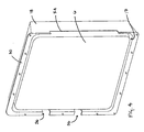
inspection door 50 is preferably included inhousing 18.Inspection door 50 is a door that may be removed to perform inspection of the contents ofhousing 18.Inspection door 50 is hinged or removably coupled tohousing 18, withconnectors 52, so that it covers an aperture that extends through the wall ofhousing 18.Inspection door 50 may be removable if desired. The size and position ofinspection door 50 may be selected so that any portion of the contents ofhousing 18 may be inspected and/or maintained. - Although in the present embodiment, latches 22 and
fluid conduits 46 are exposed to the interior of baggage compartment 4, it should be appreciated thathousing 18 may include a second cavity configured to coverlatches 22 and a portion offluid conduits 46. An access door, similar toinspection door 50 may be included on the second cavity so that the components in the second cavity may be accessed for inspection and/or maintenance. Alternatively, a separate cover, or housing, may be provided to cover those components. - A door closer 60 may also be provided that is coupled to
compartment door 12 and the interior ofbaggage compartment 14. Door closer 60 is configured to urgecompartment door 12 into a closed configuration. Any type of door closer, such as a gas cylinder, may be utilized. - Deployment of emergency inflatable equipment is preferably a two stage process. First, responsive to an emergency event, latches 22 are released which releases
pod door 20. As a result,pod door 20 is free to swing to the opened position, as shown inFIG. 6 . Afterlatches 22 are released, inflatable body 6 is inflated and deployed, as shown inFIG. 7 . As described above, latches 22 may be configured so that they dictate the sequence of unlatching oflatches 22 and inflation of inflatable body 6. Alternatively, a separate inflation valve may be utilized that is opened after latches are released. Preferably, inflatable body 6 is packed and stored so that during inflation it is predisposed to eject outward fromcavity 17. - In another embodiment, shown in
FIGS. 8 and9 , thedoor pod assembly 102 is configured as a self-contained unit. It should be appreciated that the present embodiment includes many of the features described above with respect to the previous embodiment.Door pod assembly 102 is configured so that it is installed on an aircraft in a two-step process.First housing 118 is coupled to an interior surface of a compartment door. Second, a fluid supply line is coupled tofluid conduits 156 adjacent the hose hinge assembly. - In this embodiment, a portion of
housing 118 surroundingpod door 120 extends into the door pod aperture ofcompartment door 112 and provides a frame forpod door 120, as shown inFIG. 9 . As a result a portion of the exterior surface ofhousing 118 and the exterior surface ofpod door 120 are flush with the exterior surface ofside panel 110. Furthermore,pod door 120 is hinged directly withhousing 118 and seats against a shoulder provided on the interior ofhousing 118. -
Housing 118 also includes mounting portions forlatches 122 andfluid conduits 156. As a result, the emergency equipment may be pre-loaded into the cavity defined byhousing 118, latches 122 may be mounted onhousing 118 andpod door 120 may be coupled tohousing 118, placed in a closed position and latched prior to installation ofpod assembly 102 on an aircraft. - While embodiments of the invention have been described above, it will be apparent to one skilled in the art that various changes and modifications may be made.
Claims (11)
- A door pod assembly (2) for mounting to a baggage compartment door (12) of an aircraft having an interior side and an exterior side, comprising:a housing (18) defining a cavity (17);a pod door (20) pivotally coupled to the compartment door and configured so that it encloses the cavity when said housing is mounted on said compartment door and said pod door is in a closed position;emergency equipment disposed in the cavity and including at least one inflatable body; anda latch (22) configured to selectively retain the pod door in a closed configuration relative to the compartment door, wherein the pod door is configured to open to the exterior of the aircraft such that the cavity is accessible from the exterior of the aircraft,characterized by:an inspection door (50) that is movably coupled to the housing, wherein the inspection door is configured to close an inspection aperture that extends through the housing when the inspection door is in a closed position; andwherein the housing is releasably mountable on the compartment door.
- The door pod assembly of claim 1, wherein the housing includes a mounting flange (30) that is configured to be coupled to an interior surface of the compartment door.
- The door pod assembly of claim 1, wherein the pod door is configured to fit inside a door pod aperture included in the compartment door.
- The door pod assembly of claim 1, wherein the pod door includes a lock tab (40) that extends from an interior surface of the pod door.
- The door pod assembly of claim 4, wherein the latch includes a lock pin that engages an aperture in the lock tab when the pod door is in the closed position.
- The door pod assembly of claim 1, wherein the latch is pneumatic.
- The door pod assembly of claim 6, further comprising a fluid conduit (46) configured to extend between a fluid source and the latch.
- The door pod assembly of claim 7, wherein the latch includes a lock pin and a portion of the lock pin blocks fluid communication between a fluid inlet and a fluid outlet of the latch when the latch is configured to retain the pod door in the closed position.
- The door pod assembly of claim 8, further comprising a fluid conduit (46) that extends from the outlet of the latch to an inlet of the inflatable body.
- The door pod assembly of claim 6, further comprising a fluid conduit (46) configured to extend between a fluid source and the latch, wherein a portion of the fluid conduit is coupled to the housing.
- The door pod assembly of claim 10, further comprising a hose hinge assembly that forms a portion of the fluid conduit.
Applications Claiming Priority (2)
| Application Number | Priority Date | Filing Date | Title |
|---|---|---|---|
| US77634906P | 2006-02-24 | 2006-02-24 | |
| PCT/US2007/004593 WO2007100601A2 (en) | 2006-02-24 | 2007-02-22 | Door pod assembly |
Publications (3)
| Publication Number | Publication Date |
|---|---|
| EP1989108A2 EP1989108A2 (en) | 2008-11-12 |
| EP1989108A4 EP1989108A4 (en) | 2012-10-10 |
| EP1989108B1 true EP1989108B1 (en) | 2015-07-01 |
Family
ID=38459539
Family Applications (1)
| Application Number | Title | Priority Date | Filing Date |
|---|---|---|---|
| EP07751362.0A Active EP1989108B1 (en) | 2006-02-24 | 2007-02-22 | Door pod assembly |
Country Status (4)
| Country | Link |
|---|---|
| US (1) | US7823835B2 (en) |
| EP (1) | EP1989108B1 (en) |
| CA (1) | CA2643311C (en) |
| WO (1) | WO2007100601A2 (en) |
Families Citing this family (15)
| Publication number | Priority date | Publication date | Assignee | Title |
|---|---|---|---|---|
| US7329164B2 (en) * | 2006-02-24 | 2008-02-12 | Apical Industries, Inc. | Pressure activated latch |
| DE102009058437B4 (en) * | 2009-12-16 | 2011-11-10 | Airbus Operations Gmbh | Storage system for an emergency equipment |
| US9238508B2 (en) * | 2011-02-02 | 2016-01-19 | Textron Innovations Inc. | Window mounted raft system |
| US9476251B2 (en) | 2011-08-19 | 2016-10-25 | Aerovironment, Inc. | Water-tight compartment with removable hatch and two-sided gel seal for multiple conduit access |
| US9630699B2 (en) * | 2015-02-12 | 2017-04-25 | Northrop Grumman Systems Corporation | Magnetic latching system with inflatable seal |
| US9611042B1 (en) | 2015-11-19 | 2017-04-04 | International Business Machines Corporation | System for securing an aircraft door |
| FR3046779B1 (en) * | 2016-01-14 | 2018-02-16 | Dassault Aviation | SYSTEM FOR PACKAGING A PACKAGE FROM AN AIRCRAFT, AIRCRAFT AND ASSOCIATED METHOD |
| US10513323B2 (en) * | 2017-01-06 | 2019-12-24 | The Boeing Company | Systems and methods for controlling moisture ingress in aircraft skin mounted electronics |
| US9689412B1 (en) * | 2017-02-01 | 2017-06-27 | Northrop Grumman Systems Corporation | Method and apparatus for magnetic panel attachment |
| US10850858B2 (en) * | 2017-06-28 | 2020-12-01 | Textron Innovations Inc. | Breakaway cover for emergency access |
| DE102018121305A1 (en) * | 2018-08-31 | 2020-03-05 | Airbus Operations Gmbh | Aircraft door, aircraft area and aircraft with an aircraft door |
| US11358702B2 (en) | 2019-01-11 | 2022-06-14 | The Boeing Company | Aircraft security door and method and apparatus for security door handling |
| USD1126104S1 (en) * | 2022-10-27 | 2026-05-12 | Icarus Aero Inc. | Emergency hatch for aircraft |
| WO2025128093A1 (en) * | 2023-12-13 | 2025-06-19 | Air Cruisers Company, LLC | Flexible enclosure housing for inflatable evacuation equipment |
| WO2025128094A1 (en) * | 2023-12-13 | 2025-06-19 | Air Cruisers Company, LLC | System and method for packing inflatable safety equipment |
Family Cites Families (22)
| Publication number | Priority date | Publication date | Assignee | Title |
|---|---|---|---|---|
| US1776865A (en) * | 1929-10-18 | 1930-09-30 | Glenn L Martin Co | Airplane flotation system |
| US2264321A (en) | 1939-12-26 | 1941-12-02 | Frank G Manson | Lifesaving apparatus |
| US2934293A (en) * | 1957-12-16 | 1960-04-26 | Lockheed Aircraft Corp | Emergency oxygen system for high altitude aircraft |
| US3536070A (en) * | 1967-04-03 | 1970-10-27 | Automatic Sprinkler Corp | Chemical solid state breathing fluid supply system |
| US3503394A (en) * | 1968-07-22 | 1970-03-31 | Sierra Eng Co | Modulized passenger mask assembly |
| US3771749A (en) * | 1973-01-05 | 1973-11-13 | Garrett Corp | Emergency aircraft evacuation apparatus and method |
| US3910532A (en) * | 1974-04-25 | 1975-10-07 | Garrett Corp | Inflatable deployment system and method |
| DE2532350A1 (en) * | 1975-07-19 | 1977-02-03 | Ver Flugtechnische Werke | DEVICE FOR SECURING DOOR OR FLAP LOCKING IN AIRPLANES |
| US4013247A (en) * | 1975-12-30 | 1977-03-22 | The Boeing Company | Mechanical support apparatus for the stabilization of an inflatable escape slide |
| US4375876A (en) * | 1981-06-04 | 1983-03-08 | The Boeing Company | Overhead sliding door and foldable cabin panel assembly for an airplane |
| US4909247A (en) * | 1988-05-06 | 1990-03-20 | Figgie International, Inc. | Aircraft emergency breathing assembly |
| FR2666061B1 (en) * | 1990-08-24 | 1995-06-30 | Louis Olivier | WATER SURVIVAL DEVICE. |
| US5102070A (en) * | 1991-06-13 | 1992-04-07 | Air Cruisers Company | Inflatable aircraft evacuation slide arrangement |
| US5586615A (en) * | 1995-06-07 | 1996-12-24 | Simula Inc. | Vacuum packaged escape slide |
| US5895354A (en) * | 1996-06-26 | 1999-04-20 | Simmons; Paul L. | Integrated medical diagnostic center |
| US5931415A (en) * | 1997-05-09 | 1999-08-03 | The Boeing Company | Plug-type overwing emergency exit door assembly |
| US6318364B1 (en) * | 1999-07-05 | 2001-11-20 | Be Intellectual Property, Inc. | Modular drop out container for aircraft oxygen masks |
| FR2807388B1 (en) * | 2000-04-07 | 2002-06-28 | Aerospatiale Matra Airbus | AIRCRAFT DOOR AND AIRCRAFT EQUIPPED WITH SUCH A DOOR |
| FR2824312B1 (en) * | 2001-05-02 | 2004-07-02 | Eads Airbus Sa | FAST EVACUATION DEVICE, FOR AIRCRAFT |
| US6769647B2 (en) * | 2002-04-18 | 2004-08-03 | Goodrich Corporation | Automatic inflation system for evacuation slide |
| US6659404B1 (en) * | 2002-12-23 | 2003-12-09 | Goodrich Corporation | Overboard venting inflation system and control valve therefor |
| US7380755B2 (en) * | 2005-05-26 | 2008-06-03 | Goodrich Corporation | Frangible pneumatic latch |
-
2007
- 2007-02-22 EP EP07751362.0A patent/EP1989108B1/en active Active
- 2007-02-22 US US11/710,037 patent/US7823835B2/en active Active
- 2007-02-22 CA CA2643311A patent/CA2643311C/en active Active
- 2007-02-22 WO PCT/US2007/004593 patent/WO2007100601A2/en not_active Ceased
Also Published As
| Publication number | Publication date |
|---|---|
| EP1989108A4 (en) | 2012-10-10 |
| WO2007100601A3 (en) | 2008-01-24 |
| CA2643311A1 (en) | 2007-09-07 |
| US20070199188A1 (en) | 2007-08-30 |
| CA2643311C (en) | 2014-03-25 |
| US7823835B2 (en) | 2010-11-02 |
| WO2007100601A2 (en) | 2007-09-07 |
| EP1989108A2 (en) | 2008-11-12 |
Similar Documents
| Publication | Publication Date | Title |
|---|---|---|
| CA2643311C (en) | Door pod assembly | |
| CA2643317C (en) | Pressure activated latch | |
| DE69204367T2 (en) | Inflatable slide for airplane. | |
| US7644739B1 (en) | Pressurized actuation system for inflatable structures | |
| US9718554B2 (en) | Window mounted raft system | |
| JPS6141646A (en) | Lifesaving device | |
| US10464672B2 (en) | System for dropping a package from an aircraft, related aircraft and method | |
| CA2643318C (en) | Actuator box assembly | |
| EP1989141B1 (en) | Hose hinge assembly | |
| CN107813945A (en) | Release system for evacuation-slide component | |
| EP2665525B1 (en) | Vertical drop out box method and apparatus | |
| US7434600B1 (en) | Pressurized actuator system for inflatable structures | |
| US12459656B2 (en) | Regulator with orientation valve | |
| EP3323729B1 (en) | Aspirator assembly with integrated pressure relief valve | |
| US20230129515A1 (en) | Multi-stage evacuation systems and methods for aircraft | |
| US9989166B2 (en) | Directly coupled valve actuator for inflatable structures | |
| US12330797B2 (en) | Multi-stage evacuation systems and methods for aircraft | |
| US20120042965A1 (en) | Apparatus and Method for Mounting an Inflator, Exhaust Valve or Relief Valve Interiorly of an Inflatable Article | |
| US11999494B2 (en) | Multi-stage evacuation systems and methods for aircraft | |
| CN218400924U (en) | Water area lifesaving wrist strap convenient to unfold | |
| JPS5814360B2 (en) | Swim bladder inflation device | |
| WO2025128094A1 (en) | System and method for packing inflatable safety equipment |
Legal Events
| Date | Code | Title | Description |
|---|---|---|---|
| PUAI | Public reference made under article 153(3) epc to a published international application that has entered the european phase |
Free format text: ORIGINAL CODE: 0009012 |
|
| 17P | Request for examination filed |
Effective date: 20080924 |
|
| AK | Designated contracting states |
Kind code of ref document: A2 Designated state(s): AT BE BG CH CY CZ DE DK EE ES FI FR GB GR HU IE IS IT LI LT LU LV MC NL PL PT RO SE SI SK TR |
|
| DAX | Request for extension of the european patent (deleted) | ||
| A4 | Supplementary search report drawn up and despatched |
Effective date: 20120906 |
|
| RIC1 | Information provided on ipc code assigned before grant |
Ipc: B63B 23/00 20060101ALI20120831BHEP Ipc: B64D 17/40 20060101ALI20120831BHEP Ipc: B64C 1/22 20060101ALI20120831BHEP Ipc: A62B 1/20 20060101ALI20120831BHEP Ipc: B64C 1/14 20060101ALI20120831BHEP Ipc: B64D 17/00 20060101ALI20120831BHEP Ipc: B64D 11/00 20060101AFI20120831BHEP |
|
| GRAP | Despatch of communication of intention to grant a patent |
Free format text: ORIGINAL CODE: EPIDOSNIGR1 |
|
| INTG | Intention to grant announced |
Effective date: 20150114 |
|
| GRAS | Grant fee paid |
Free format text: ORIGINAL CODE: EPIDOSNIGR3 |
|
| GRAA | (expected) grant |
Free format text: ORIGINAL CODE: 0009210 |
|
| AK | Designated contracting states |
Kind code of ref document: B1 Designated state(s): AT BE BG CH CY CZ DE DK EE ES FI FR GB GR HU IE IS IT LI LT LU LV MC NL PL PT RO SE SI SK TR |
|
| REG | Reference to a national code |
Ref country code: GB Ref legal event code: FG4D |
|
| REG | Reference to a national code |
Ref country code: AT Ref legal event code: REF Ref document number: 733790 Country of ref document: AT Kind code of ref document: T Effective date: 20150715 Ref country code: CH Ref legal event code: EP |
|
| REG | Reference to a national code |
Ref country code: IE Ref legal event code: FG4D |
|
| REG | Reference to a national code |
Ref country code: DE Ref legal event code: R096 Ref document number: 602007041944 Country of ref document: DE |
|
| REG | Reference to a national code |
Ref country code: AT Ref legal event code: MK05 Ref document number: 733790 Country of ref document: AT Kind code of ref document: T Effective date: 20150701 |
|
| REG | Reference to a national code |
Ref country code: NL Ref legal event code: MP Effective date: 20150701 |
|
| REG | Reference to a national code |
Ref country code: LT Ref legal event code: MG4D |
|
| REG | Reference to a national code |
Ref country code: FR Ref legal event code: PLFP Year of fee payment: 10 |
|
| PG25 | Lapsed in a contracting state [announced via postgrant information from national office to epo] |
Ref country code: FI Free format text: LAPSE BECAUSE OF FAILURE TO SUBMIT A TRANSLATION OF THE DESCRIPTION OR TO PAY THE FEE WITHIN THE PRESCRIBED TIME-LIMIT Effective date: 20150701 Ref country code: LV Free format text: LAPSE BECAUSE OF FAILURE TO SUBMIT A TRANSLATION OF THE DESCRIPTION OR TO PAY THE FEE WITHIN THE PRESCRIBED TIME-LIMIT Effective date: 20150701 Ref country code: GR Free format text: LAPSE BECAUSE OF FAILURE TO SUBMIT A TRANSLATION OF THE DESCRIPTION OR TO PAY THE FEE WITHIN THE PRESCRIBED TIME-LIMIT Effective date: 20151002 Ref country code: LT Free format text: LAPSE BECAUSE OF FAILURE TO SUBMIT A TRANSLATION OF THE DESCRIPTION OR TO PAY THE FEE WITHIN THE PRESCRIBED TIME-LIMIT Effective date: 20150701 |
|
| PG25 | Lapsed in a contracting state [announced via postgrant information from national office to epo] |
Ref country code: ES Free format text: LAPSE BECAUSE OF FAILURE TO SUBMIT A TRANSLATION OF THE DESCRIPTION OR TO PAY THE FEE WITHIN THE PRESCRIBED TIME-LIMIT Effective date: 20150701 Ref country code: PL Free format text: LAPSE BECAUSE OF FAILURE TO SUBMIT A TRANSLATION OF THE DESCRIPTION OR TO PAY THE FEE WITHIN THE PRESCRIBED TIME-LIMIT Effective date: 20150701 Ref country code: IS Free format text: LAPSE BECAUSE OF FAILURE TO SUBMIT A TRANSLATION OF THE DESCRIPTION OR TO PAY THE FEE WITHIN THE PRESCRIBED TIME-LIMIT Effective date: 20151101 Ref country code: PT Free format text: LAPSE BECAUSE OF FAILURE TO SUBMIT A TRANSLATION OF THE DESCRIPTION OR TO PAY THE FEE WITHIN THE PRESCRIBED TIME-LIMIT Effective date: 20151102 Ref country code: AT Free format text: LAPSE BECAUSE OF FAILURE TO SUBMIT A TRANSLATION OF THE DESCRIPTION OR TO PAY THE FEE WITHIN THE PRESCRIBED TIME-LIMIT Effective date: 20150701 Ref country code: SE Free format text: LAPSE BECAUSE OF FAILURE TO SUBMIT A TRANSLATION OF THE DESCRIPTION OR TO PAY THE FEE WITHIN THE PRESCRIBED TIME-LIMIT Effective date: 20150701 |
|
| REG | Reference to a national code |
Ref country code: DE Ref legal event code: R097 Ref document number: 602007041944 Country of ref document: DE |
|
| PG25 | Lapsed in a contracting state [announced via postgrant information from national office to epo] |
Ref country code: DK Free format text: LAPSE BECAUSE OF FAILURE TO SUBMIT A TRANSLATION OF THE DESCRIPTION OR TO PAY THE FEE WITHIN THE PRESCRIBED TIME-LIMIT Effective date: 20150701 Ref country code: SK Free format text: LAPSE BECAUSE OF FAILURE TO SUBMIT A TRANSLATION OF THE DESCRIPTION OR TO PAY THE FEE WITHIN THE PRESCRIBED TIME-LIMIT Effective date: 20150701 Ref country code: CZ Free format text: LAPSE BECAUSE OF FAILURE TO SUBMIT A TRANSLATION OF THE DESCRIPTION OR TO PAY THE FEE WITHIN THE PRESCRIBED TIME-LIMIT Effective date: 20150701 Ref country code: EE Free format text: LAPSE BECAUSE OF FAILURE TO SUBMIT A TRANSLATION OF THE DESCRIPTION OR TO PAY THE FEE WITHIN THE PRESCRIBED TIME-LIMIT Effective date: 20150701 Ref country code: IT Free format text: LAPSE BECAUSE OF FAILURE TO SUBMIT A TRANSLATION OF THE DESCRIPTION OR TO PAY THE FEE WITHIN THE PRESCRIBED TIME-LIMIT Effective date: 20150701 |
|
| PLBE | No opposition filed within time limit |
Free format text: ORIGINAL CODE: 0009261 |
|
| STAA | Information on the status of an ep patent application or granted ep patent |
Free format text: STATUS: NO OPPOSITION FILED WITHIN TIME LIMIT |
|
| PG25 | Lapsed in a contracting state [announced via postgrant information from national office to epo] |
Ref country code: BE Free format text: LAPSE BECAUSE OF NON-PAYMENT OF DUE FEES Effective date: 20160229 Ref country code: RO Free format text: LAPSE BECAUSE OF FAILURE TO SUBMIT A TRANSLATION OF THE DESCRIPTION OR TO PAY THE FEE WITHIN THE PRESCRIBED TIME-LIMIT Effective date: 20150701 |
|
| 26N | No opposition filed |
Effective date: 20160404 |
|
| PG25 | Lapsed in a contracting state [announced via postgrant information from national office to epo] |
Ref country code: SI Free format text: LAPSE BECAUSE OF FAILURE TO SUBMIT A TRANSLATION OF THE DESCRIPTION OR TO PAY THE FEE WITHIN THE PRESCRIBED TIME-LIMIT Effective date: 20150701 |
|
| PG25 | Lapsed in a contracting state [announced via postgrant information from national office to epo] |
Ref country code: MC Free format text: LAPSE BECAUSE OF FAILURE TO SUBMIT A TRANSLATION OF THE DESCRIPTION OR TO PAY THE FEE WITHIN THE PRESCRIBED TIME-LIMIT Effective date: 20150701 Ref country code: LU Free format text: LAPSE BECAUSE OF FAILURE TO SUBMIT A TRANSLATION OF THE DESCRIPTION OR TO PAY THE FEE WITHIN THE PRESCRIBED TIME-LIMIT Effective date: 20160222 |
|
| REG | Reference to a national code |
Ref country code: CH Ref legal event code: PL |
|
| PG25 | Lapsed in a contracting state [announced via postgrant information from national office to epo] |
Ref country code: LI Free format text: LAPSE BECAUSE OF NON-PAYMENT OF DUE FEES Effective date: 20160229 Ref country code: CH Free format text: LAPSE BECAUSE OF NON-PAYMENT OF DUE FEES Effective date: 20160229 |
|
| REG | Reference to a national code |
Ref country code: IE Ref legal event code: MM4A |
|
| PG25 | Lapsed in a contracting state [announced via postgrant information from national office to epo] |
Ref country code: BE Free format text: LAPSE BECAUSE OF FAILURE TO SUBMIT A TRANSLATION OF THE DESCRIPTION OR TO PAY THE FEE WITHIN THE PRESCRIBED TIME-LIMIT Effective date: 20150701 |
|
| REG | Reference to a national code |
Ref country code: FR Ref legal event code: PLFP Year of fee payment: 11 |
|
| PG25 | Lapsed in a contracting state [announced via postgrant information from national office to epo] |
Ref country code: IE Free format text: LAPSE BECAUSE OF NON-PAYMENT OF DUE FEES Effective date: 20160222 |
|
| PG25 | Lapsed in a contracting state [announced via postgrant information from national office to epo] |
Ref country code: NL Free format text: LAPSE BECAUSE OF FAILURE TO SUBMIT A TRANSLATION OF THE DESCRIPTION OR TO PAY THE FEE WITHIN THE PRESCRIBED TIME-LIMIT Effective date: 20150701 |
|
| REG | Reference to a national code |
Ref country code: FR Ref legal event code: PLFP Year of fee payment: 12 |
|
| PG25 | Lapsed in a contracting state [announced via postgrant information from national office to epo] |
Ref country code: CY Free format text: LAPSE BECAUSE OF FAILURE TO SUBMIT A TRANSLATION OF THE DESCRIPTION OR TO PAY THE FEE WITHIN THE PRESCRIBED TIME-LIMIT Effective date: 20150701 Ref country code: HU Free format text: LAPSE BECAUSE OF FAILURE TO SUBMIT A TRANSLATION OF THE DESCRIPTION OR TO PAY THE FEE WITHIN THE PRESCRIBED TIME-LIMIT; INVALID AB INITIO Effective date: 20070222 |
|
| PG25 | Lapsed in a contracting state [announced via postgrant information from national office to epo] |
Ref country code: TR Free format text: LAPSE BECAUSE OF FAILURE TO SUBMIT A TRANSLATION OF THE DESCRIPTION OR TO PAY THE FEE WITHIN THE PRESCRIBED TIME-LIMIT Effective date: 20150701 |
|
| PG25 | Lapsed in a contracting state [announced via postgrant information from national office to epo] |
Ref country code: BG Free format text: LAPSE BECAUSE OF FAILURE TO SUBMIT A TRANSLATION OF THE DESCRIPTION OR TO PAY THE FEE WITHIN THE PRESCRIBED TIME-LIMIT Effective date: 20150701 |
|
| PGFP | Annual fee paid to national office [announced via postgrant information from national office to epo] |
Ref country code: FR Payment date: 20251231 Year of fee payment: 20 |
|
| PGFP | Annual fee paid to national office [announced via postgrant information from national office to epo] |
Ref country code: GB Payment date: 20260106 Year of fee payment: 20 |
|
| PGFP | Annual fee paid to national office [announced via postgrant information from national office to epo] |
Ref country code: DE Payment date: 20251230 Year of fee payment: 20 |