EP1988835B1 - Eyeless sewing needle and fabrication method for the same - Google Patents
Eyeless sewing needle and fabrication method for the same Download PDFInfo
- Publication number
- EP1988835B1 EP1988835B1 EP07737747.1A EP07737747A EP1988835B1 EP 1988835 B1 EP1988835 B1 EP 1988835B1 EP 07737747 A EP07737747 A EP 07737747A EP 1988835 B1 EP1988835 B1 EP 1988835B1
- Authority
- EP
- European Patent Office
- Prior art keywords
- axial hole
- sewing needle
- main body
- base end
- needle
- Prior art date
- Legal status (The legal status is an assumption and is not a legal conclusion. Google has not performed a legal analysis and makes no representation as to the accuracy of the status listed.)
- Active
Links
Images

Classifications
-
- B—PERFORMING OPERATIONS; TRANSPORTING
- B21—MECHANICAL METAL-WORKING WITHOUT ESSENTIALLY REMOVING MATERIAL; PUNCHING METAL
- B21G—MAKING NEEDLES, PINS OR NAILS OF METAL
- B21G1/00—Making needles used for performing operations
- B21G1/08—Making needles used for performing operations of hollow needles or needles with hollow end, e.g. hypodermic needles, larding-needles
-
- A—HUMAN NECESSITIES
- A61—MEDICAL OR VETERINARY SCIENCE; HYGIENE
- A61B—DIAGNOSIS; SURGERY; IDENTIFICATION
- A61B17/00—Surgical instruments, devices or methods
- A61B17/04—Surgical instruments, devices or methods for suturing wounds; Holders or packages for needles or suture materials
- A61B17/06—Needles ; Sutures; Needle-suture combinations; Holders or packages for needles or suture materials
- A61B17/06066—Needles, e.g. needle tip configurations
-
- A—HUMAN NECESSITIES
- A61—MEDICAL OR VETERINARY SCIENCE; HYGIENE
- A61B—DIAGNOSIS; SURGERY; IDENTIFICATION
- A61B17/00—Surgical instruments, devices or methods
- A61B17/04—Surgical instruments, devices or methods for suturing wounds; Holders or packages for needles or suture materials
- A61B17/06—Needles ; Sutures; Needle-suture combinations; Holders or packages for needles or suture materials
-
- C—CHEMISTRY; METALLURGY
- C21—METALLURGY OF IRON
- C21D—MODIFYING THE PHYSICAL STRUCTURE OF FERROUS METALS; GENERAL DEVICES FOR HEAT TREATMENT OF FERROUS OR NON-FERROUS METALS OR ALLOYS; MAKING METAL MALLEABLE, e.g. BY DECARBURISATION OR TEMPERING
- C21D1/00—General methods or devices for heat treatment, e.g. annealing, hardening, quenching or tempering
- C21D1/26—Methods of annealing
-
- C—CHEMISTRY; METALLURGY
- C21—METALLURGY OF IRON
- C21D—MODIFYING THE PHYSICAL STRUCTURE OF FERROUS METALS; GENERAL DEVICES FOR HEAT TREATMENT OF FERROUS OR NON-FERROUS METALS OR ALLOYS; MAKING METAL MALLEABLE, e.g. BY DECARBURISATION OR TEMPERING
- C21D1/00—General methods or devices for heat treatment, e.g. annealing, hardening, quenching or tempering
- C21D1/34—Methods of heating
- C21D1/52—Methods of heating with flames
-
- C—CHEMISTRY; METALLURGY
- C21—METALLURGY OF IRON
- C21D—MODIFYING THE PHYSICAL STRUCTURE OF FERROUS METALS; GENERAL DEVICES FOR HEAT TREATMENT OF FERROUS OR NON-FERROUS METALS OR ALLOYS; MAKING METAL MALLEABLE, e.g. BY DECARBURISATION OR TEMPERING
- C21D9/00—Heat treatment, e.g. annealing, hardening, quenching or tempering, adapted for particular articles; Furnaces therefor
- C21D9/26—Heat treatment, e.g. annealing, hardening, quenching or tempering, adapted for particular articles; Furnaces therefor for needles; for teeth for card-clothing
-
- A—HUMAN NECESSITIES
- A61—MEDICAL OR VETERINARY SCIENCE; HYGIENE
- A61B—DIAGNOSIS; SURGERY; IDENTIFICATION
- A61B17/00—Surgical instruments, devices or methods
- A61B17/04—Surgical instruments, devices or methods for suturing wounds; Holders or packages for needles or suture materials
- A61B17/06—Needles ; Sutures; Needle-suture combinations; Holders or packages for needles or suture materials
- A61B17/06004—Means for attaching suture to needle
- A61B2017/06028—Means for attaching suture to needle by means of a cylindrical longitudinal blind bore machined at the suture-receiving end of the needle, e.g. opposite to needle tip
-
- C—CHEMISTRY; METALLURGY
- C21—METALLURGY OF IRON
- C21D—MODIFYING THE PHYSICAL STRUCTURE OF FERROUS METALS; GENERAL DEVICES FOR HEAT TREATMENT OF FERROUS OR NON-FERROUS METALS OR ALLOYS; MAKING METAL MALLEABLE, e.g. BY DECARBURISATION OR TEMPERING
- C21D1/00—General methods or devices for heat treatment, e.g. annealing, hardening, quenching or tempering
- C21D1/26—Methods of annealing
- C21D1/30—Stress-relieving
-
- C—CHEMISTRY; METALLURGY
- C21—METALLURGY OF IRON
- C21D—MODIFYING THE PHYSICAL STRUCTURE OF FERROUS METALS; GENERAL DEVICES FOR HEAT TREATMENT OF FERROUS OR NON-FERROUS METALS OR ALLOYS; MAKING METAL MALLEABLE, e.g. BY DECARBURISATION OR TEMPERING
- C21D2211/00—Microstructure comprising significant phases
- C21D2211/001—Austenite
-
- Y—GENERAL TAGGING OF NEW TECHNOLOGICAL DEVELOPMENTS; GENERAL TAGGING OF CROSS-SECTIONAL TECHNOLOGIES SPANNING OVER SEVERAL SECTIONS OF THE IPC; TECHNICAL SUBJECTS COVERED BY FORMER USPC CROSS-REFERENCE ART COLLECTIONS [XRACs] AND DIGESTS
- Y10—TECHNICAL SUBJECTS COVERED BY FORMER USPC
- Y10T—TECHNICAL SUBJECTS COVERED BY FORMER US CLASSIFICATION
- Y10T29/00—Metal working
- Y10T29/49—Method of mechanical manufacture
- Y10T29/49826—Assembling or joining
Definitions
- the present invention relates to an eyeless sewing needle and a fabrication method for the same. It particularly relates to an eyeless sewing needle made of austenitic stainless steel having a fibrous crystalline structure extending along the length of the sewing needle.
- Stainless steel is a suitable material for sewing needles to be used in surgical operations.
- wire rods each 6 to 10 mm in diameter are used as the material.
- wire drawing is carried out repeatedly thereto, providing wires each having the diameter of a sewing needle being fabricated.
- a solution heat treatment is carried out between each wire drawing.
- wires are cut at an appropriate length, and tips thereof are then sharpened by grinding using a grindstone into a cone or pyramid shape, which is then incurvated through machining and a hole passing through from a base end towards the tip side is made using a drill or a laser. Afterwards, the tip is mainly quenched, and a suture thread is inserted in the above-mentioned hole, and crimped and fixed.
- precipitation hardening stainless steel once wire drawing and the solution heat treatment are carried out repeatedly until the thickness of the sewing needle is reached, it is cut at a predetermined length, the tip is sharpened as mentioned above, and then a hole is made in the base end. Afterwards, precipitation hardening other than quenching is carried out.
- Japanese Patent Publication after examination (Kokoku) No. Hei 1-11084 proposes a fabrication method for completing a product by using austenitic stainless steel wires extended at an 80% or greater cross-sectional area reduction rate, and in subsequent processing, carrying out predetermined processing on these steel wires while always maintaining at a temperature below approximately 500°C. Since hardness increased through work hardening, or strain hardening decreases when exceeding 500°C, the temperature is set to no greater than 500°C. While austenitic stainless steel cannot be quenched, work hardening at the time of wire drawing is utilized instead. Utilization of austenitic stainless steel allows improvement in corrosion resistance. Furthermore, since quenching is impossible, the problem of cracking or chipping does not occur by contrast.
- the austenitic stainless steel extended to a predetermined diameter in this manner becomes a thin fibrous structure with crystal grains extending along the line length, providing the necessary hardness for a sewing needle.
- these stainless steel wires are cut to a predetermined length, tips thereof are sharpened into a conical or pyramid shape, and then a hole is made in the base end side using a drill or laser.
- the needle should be gripped on the tip side, for example, a position approximately a third of the needle length from the needle base; however, depending upon suturing portions, there is a case where it is easier to suture by gripping closer to the hole, for example, a position approximately a quarter to a fifth of the needle length from the needle base. Needing to always grip on the tip side of the needle is stressful for the doctor.
- US 5 012 066 A shows a method of and apparatus for manufacturing eyeless suture needle, in which for annealing a proximal end portion of a needle material for a suture needle, an energy beam is applied to a proximal end face of the needle material.
- the laser beam from the oscillator is supplied to the proximal end face of the needle material through a condenser lens.
- the laser beam is smoothed by a smoothing member, and is applied to the proximal end face of the needle material.
- the present invention is devised through consideration of the aforementioned problems.
- An objective thereof is to provide a sewing needle impossible to bend even if gripped near the hole, and also provide a fabrication method for the same.
- the sewing needle of the present invention is flexible near the hole so as to allow the hole periphery to be easily crimped while keeping a high hardness at a position slightly away from the hole towards the needlepoint side.
- the eyeless sewing needle includes a curved axial main body extending from a base end to a sharp needlepoint and is made of austenitic stainless steel with a fibrous structure in which a crystalline structure of the main body extending axially. It further includes an axial hole extending from the base end.
- a periphery of the axial hole at the base end is heated to make the fibrous structure be a granular structure without directionality, and at least a part of a heat-affected zone made between the fibrous structure arid the granular structure through the heating is within a range that is three times the diameter of the sewing needle and that extends from an effective base of the hole towards the needlepoint of the sewing needle.
- a range approximately a quarter of the needle length away from the base end of the main body and further to the needlepoint does not include a granular crystalline structure but will include the heat-affected zone or a fibrous crystalline structure.
- a fabrication method for an eyeless sewing needle including a curved axial main body extending from a base end to a sharp needlepoint and further including an axial hole extending from the base end is provided; wherein the main body has a crystalline structure made of austenitic stainless steel with a fibrous structure extending axially.
- This method is characterized by the steps of: heating the periphery of the axial hole at the base end to make the fibrous structure be a granular structure without directionality; and forming a heat-affected zone between the fibrous structure and the granular structure through the heating. At least a part of the heat-affected zone resides in the range that is three times the diameter of the sewing needle and that extends from an effective base of the hole towards the needlepoint of the sewing needle.
- the fabrication method for the eyeless sewing needle is characterized in that a range approximately a quarter of the needle length away from the base end of the main body and further to the needlepoint does not include a granular crystalline structure but includes the heat-affected zone or a fibrous crystalline structure.
- the eyeless sewing needle according to the present invention has a fibrous main body, and since it is hard, the base end is heated before or after making the hole in the base end surface to make a flexible granular structure, facilitating crimping and related operations.
- the needlepoint side remains a fibrous structure, securing strength required when suturing. While the base end is heated to be a granular structure, an area adjacent to the heated part is affected by the heat, turning into an intermediate state between the fibrous and the granular structure. This area is defined as a heat-affected zone, and the length of the granular structure is determined based on the position of this heat-affected zone.
- the further this heat-affected zone is positioned away from the effective base of the hole towards the needlepoint the longer the flexible granular structure part on the base end side. If a surgeon grips near the hole of the sewing needle using a needle holder, it will easily bend. Therefore, as long as at least a part of the heat-affected zone is less than three times the needle diameter away from the effective base of the hole, the length of the flexible granular structure may be kept under three times the needle diameter away from the effective base of the hole towards the needlepoint. As a result, the sewing needle will not bend anymore, providing a convenient eyeless sewing needle, as long as it is not gripped with a needle holder very close to the needle base.
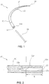
- FIG. 1 is an oblique perspective of an eyeless sewing needle according to the present invention.
- an eyeless sewing needle 10 is entirely made of austenitic stainless steel, a base end 11a is on an end of a main body 11, and an axial hole 12 is formed in this base end 11a which is cylindrically drilled along the longitudinal axis of the needle according to a processing method using a laser, an electron beam, electric discharge, a drill, or the like.
- a sharp needlepoint 14 is formed at the tip of the eyeless sewing needle 10, and a pyramid having a plurality of cutting blades 15 continuing from the needlepoint 14 is formed.
- the eyeless sewing needle 10 may be a sewing needle with a sharpened edge (not shown in the drawing) in which the cross section of the cutting blades 15 as shown in FIG. 1 is formed into a polygon, a round needle (not shown in the drawing) without the cutting blades 15 having a cross section thereof formed in an approximate circle, or the like. These sewing needles are selected and used according to anatomy and region to be sutured.
- suture thread 20 is provided in terms of different thicknesses and materials (nylon, silk, etc.) and/or different structures such as monofilament or multifilament.
- An appropriate type of suture thread is selected and used according to anatomy and region to be sutured.
- An end of the suture thread 20 is inserted in the axial hole 12, and the axial hole 12 is crushed and crimped by using a press machine, thus fixing the suture thread 20 to the base end of the eyeless sewing needle 10.
- the eyeless sewing needle 10 has an advantage in that a thread long enough for suturing is fastened from the start, and thus there is no need to pass a thread through a hole as with an eyed needle.
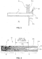
- FIG. 2 is a magnified cross section of a base end of the eyeless sewing needle 10 of FIG. 1 .
- the base end 11a of the main body 11 has the axial hole 12 opened with a laser.
- the axial hole 12 has a part 12a somewhat wider than the diameter of the suture thread 20 and nearly straight so that the suture thread 20 can be inserted.
- a bottom part 12b of the axial hole 12 gradually narrows, finally ending in a dead end.
- the suture thread 20 can be inserted only in the nearly straight part 12a.
- a virtual surface formed at the boundary of the part 12a and the part 12b is called an effective base 12c of the axial hole 12, and distance L from the base end 11a of the axial hole 12 to the effective base 12c is called an effective depth.
- the diameter of the axial hole 12 is approximately 20 to 80% of diameter (diameter of the unprocessed main body 11) of the eyeless sewing needle 10, and the effective depth L is approximately 1.1 to 7 times the diameter.
- the main body 11 of the eyeless sewing needle 10 is fibrous and hard, attaching a thread is not easy. Therefore, before or after making the axial hole 12, heating this base end part to be granular is necessary. Note that since making the axial hole 12 with a drill or the like causes work hardening at the inner surface of the axial hole 12, it is preferable to heat the base end part thereafter.
- FIG. 3 is a diagram describing this heating method.
- the main body 11 of the eyeless sewing needle before the axial hole 12 is made includes the sharp needlepoint 14 with a plurality of the cutting blades 15 connected thereto.
- This main body 11 is loaded onto a conveyer 30 and transported. At this time, the base end side of the main body 11 overhangs off from the conveyer 30 by just the effective depth L of the axial hole 12.
- An insulating board 31 and a burner 32 are provided at predetermined positions along the transporting path for the conveyer 30.
- a surface 31a on the outside of the insulating board 31 is the same as an outer surface 30a of the conveyer 30.
- the insulating board 31 may be a plaster board or one of various types of ceramics as long as it effectively shuts out heat from the burner 32.
- the overhanging length is set to L, this length is not limited thereto and should be determined based on conditions such as thickness of the eyeless sewing needle 10 and heat conditions of the burner 32.
- the eyeless sewing needle 10 that has been transported along the conveyer 30 reaches a predetermined position, it is held down from above by the insulating board 31, making a part of the base end side of the eyeless sewing needle 10 having a length "L" overhang.
- This length L part overhanging the outer side is heated to approximately 800°C by the flame of the burner 32.
- the heated eyeless sewing needle 10 is transported on the conveyer 30 away from the burner 32 and then cooled in the air. Through this heating and cooling, the base end in which the axial hole 12 is to be opened is changed and softened from having a fibrous structure to a granular structure.
- the axial hole 12 is then opened through laser processing or the like as in the conventional manner.
- FIG. 4 is a diagram schematically showing a structure of a cross section after the axial hole is made.
- the length L of the heated part is a depth represented by the effective base 12c of the axial hole, and a granular structure a exceeds the effective base 12c of the axial hole, reaching close to the bottom 12b of the axial hole 12.
- parts away from the axial hole 12 along the needle length are not affected by the heat, and thus a fibrous structure b remains the same, providing necessary hardness for the eyeless sewing needle 10.
- a heat-affected zone c is formed between the granular structure a and the fibrous structure b.
- This heat-affected zone c is a chromium deficient region from which chromium carbide is finely precipitated, and is of poor corrosion resistance. Furthermore, the hardness of this heat-affected zone c is between that of the fibrous structure b and the granular structure a.
- the heat-affected zone c is positioned in a range approximately a quarter of the needle length away from the base end 11a of the main body 11, and a fibrous crystalline structure is formed in a portion extending from a quarter of the needle length from the base end 11a toward the needlepoint side of the sewing needle.
- FIG. 5 is a diagram schematically showing a structure of a cross section of a conventional eyeless sewing needle 10'. Since the base end is conventionally merely heated without any kind of control, quite a long part from the base end 11a is heated, the part having the granular structure a extends broadly towards the needlepoint from the effective base 12c of the axial hole 12, and the heat-affected zone c is then formed thereafter. Since the granular structure a is long, it is easy to grip the part having the granular structure a with a needle holder when suturing. However, when gripping the part having the granular structure a, there is a great risk that the eyeless sewing needle 10' will be bent.
- the eyeless sewing needle 10 limits the heated part to the effective depth L of the axial hole by the use of the conveyer 30 and the insulating board 31, shortening the granular structure a is possible, as shown in FIG. 4 . More specifically, the part of the granular structure a may be almost limited to the outer vicinity of the axial hole 12.
- the present invention provides a convenient eyeless sewing needle which is impossible to bend even if gripped near the axial hole, and also provides a fabrication method for the same.
- the sewing needle of the present invention is flexible near the axial hole so as to allow the hole periphery to be easily crimped while keeping a high hardness at a position slightly away from the axial hole towards the needlepoint side.
Landscapes
- Chemical & Material Sciences (AREA)
- Engineering & Computer Science (AREA)
- Health & Medical Sciences (AREA)
- Mechanical Engineering (AREA)
- Life Sciences & Earth Sciences (AREA)
- Physics & Mathematics (AREA)
- Materials Engineering (AREA)
- Metallurgy (AREA)
- Organic Chemistry (AREA)
- Thermal Sciences (AREA)
- Crystallography & Structural Chemistry (AREA)
- Surgery (AREA)
- Medical Informatics (AREA)
- Public Health (AREA)
- Heart & Thoracic Surgery (AREA)
- Nuclear Medicine, Radiotherapy & Molecular Imaging (AREA)
- Molecular Biology (AREA)
- Animal Behavior & Ethology (AREA)
- General Health & Medical Sciences (AREA)
- Biomedical Technology (AREA)
- Veterinary Medicine (AREA)
- Surgical Instruments (AREA)
- Sewing Machines And Sewing (AREA)
- Infusion, Injection, And Reservoir Apparatuses (AREA)
- Materials For Medical Uses (AREA)
- Heat Treatment Of Articles (AREA)
Description
- The present invention relates to an eyeless sewing needle and a fabrication method for the same. It particularly relates to an eyeless sewing needle made of austenitic stainless steel having a fibrous crystalline structure extending along the length of the sewing needle.
- Stainless steel is a suitable material for sewing needles to be used in surgical operations. In the case of martensitic stainless steel, precipitation hardening stainless steel, or the like, wire rods each 6 to 10 mm in diameter are used as the material. In the case of carbon steel or martensitic stainless steel, wire drawing is carried out repeatedly thereto, providing wires each having the diameter of a sewing needle being fabricated. In the case of stainless steel, a solution heat treatment is carried out between each wire drawing.
- These wires are cut at an appropriate length, and tips thereof are then sharpened by grinding using a grindstone into a cone or pyramid shape, which is then incurvated through machining and a hole passing through from a base end towards the tip side is made using a drill or a laser. Afterwards, the tip is mainly quenched, and a suture thread is inserted in the above-mentioned hole, and crimped and fixed. In the case of precipitation hardening stainless steel, once wire drawing and the solution heat treatment are carried out repeatedly until the thickness of the sewing needle is reached, it is cut at a predetermined length, the tip is sharpened as mentioned above, and then a hole is made in the base end. Afterwards, precipitation hardening other than quenching is carried out.
- Since the above materials are soft, processing is easy, but there is a problem with quenching and precipitation hardening in that cracking, breaking, chipping, or the like easily occurs due to lack of toughness. Furthermore, there is a problem with corrosion resistance since rust easily develops due to characteristics of the materials.
- With regard to these problems,
Japanese Patent Publication after examination (Kokoku) No. Hei 1-11084 - The austenitic stainless steel extended to a predetermined diameter in this manner becomes a thin fibrous structure with crystal grains extending along the line length, providing the necessary hardness for a sewing needle. In this case, these stainless steel wires are cut to a predetermined length, tips thereof are sharpened into a conical or pyramid shape, and then a hole is made in the base end side using a drill or laser.
- However, since the entirety from the tip to the base end is a fibrous structure, it is hard, and processing such as crimping to attach a suture thread to the sewing needle is difficult. Furthermore, the hole cracks even due to crimping, causing damage to the anatomy, which thereby reduces tension of the suture thread, making it easier to pull out. Accordingly,
Japanese Patent Publication after examination (Kokoku) No. Hei 4-67978 - However, while the sewing needle described in
Japanese Patent Publication after examination (Kokoku) No. Hei 4-67978 - Note that a tendency to grip the tip side of the needle at a position approximately three times the diameter of the sewing needle from the bottom of the hole is understood.
-
US 5 012 066 A shows a method of and apparatus for manufacturing eyeless suture needle, in which for annealing a proximal end portion of a needle material for a suture needle, an energy beam is applied to a proximal end face of the needle material. For forming the mounting hole, the laser beam from the oscillator is supplied to the proximal end face of the needle material through a condenser lens. For effecting the annealing, the laser beam is smoothed by a smoothing member, and is applied to the proximal end face of the needle material. - The present invention is devised through consideration of the aforementioned problems. An objective thereof is to provide a sewing needle impossible to bend even if gripped near the hole, and also provide a fabrication method for the same.
- The object is solved according to the eyeless sewing needle of claim 1 and the relating fabrication method of claim 2. Dependent claims describe preferred embodiments of the present invention.
- For that purpose the sewing needle of the present invention is flexible near the hole so as to allow the hole periphery to be easily crimped while keeping a high hardness at a position slightly away from the hole towards the needlepoint side.
- In order to attain the objective described above, the eyeless sewing needle, according to the present invention, includes a curved axial main body extending from a base end to a sharp needlepoint and is made of austenitic stainless steel with a fibrous structure in which a crystalline structure of the main body extending axially. It further includes an axial hole extending from the base end. It is characterized in that a periphery of the axial hole at the base end is heated to make the fibrous structure be a granular structure without directionality, and at least a part of a heat-affected zone made between the fibrous structure arid the granular structure through the heating is within a range that is three times the diameter of the sewing needle and that extends from an effective base of the hole towards the needlepoint of the sewing needle.
- Furthermore, a range approximately a quarter of the needle length away from the base end of the main body and further to the needlepoint does not include a granular crystalline structure but will include the heat-affected zone
or a fibrous crystalline structure. - A fabrication method for an eyeless sewing needle including a curved axial main body extending from a base end to a sharp needlepoint and further including an axial hole extending from the base end is provided; wherein the main body has a crystalline structure made of austenitic stainless steel with a fibrous structure extending axially. This method is characterized by the steps of: heating the periphery of the axial hole at the base end to make the fibrous structure be a granular structure without directionality; and forming a heat-affected zone between the fibrous structure and the granular structure through the heating. At least a part of the heat-affected zone resides in the range that is three times the diameter of the sewing needle and that extends from an effective base of the hole towards the needlepoint of the sewing needle.
- Moreover, the fabrication method for the eyeless sewing needle, according to present invention, is characterized in that a range approximately a quarter of the needle length away from the base end of the main body and further to the needlepoint does not include a granular crystalline structure but includes the heat-affected zone or a fibrous crystalline structure.
- The eyeless sewing needle according to the present invention has a fibrous main body, and since it is hard, the base end is heated before or after making the hole in the base end surface to make a flexible granular structure, facilitating crimping and related operations. In addition, the needlepoint side remains a fibrous structure, securing strength required when suturing. While the base end is heated to be a granular structure, an area adjacent to the heated part is affected by the heat, turning into an intermediate state between the fibrous and the granular structure. This area is defined as a heat-affected zone, and the length of the granular structure is determined based on the position of this heat-affected zone. In other words, the further this heat-affected zone is positioned away from the effective base of the hole towards the needlepoint, the longer the flexible granular structure part on the base end side. If a surgeon grips near the hole of the sewing needle using a needle holder, it will easily bend. Therefore, as long as at least a part of the heat-affected zone is less than three times the needle diameter away from the effective base of the hole, the length of the flexible granular structure may be kept under three times the needle diameter away from the effective base of the hole towards the needlepoint. As a result, the sewing needle will not bend anymore, providing a convenient eyeless sewing needle, as long as it is not gripped with a needle holder very close to the needle base.
-
-
FIG. 1 is an oblique perspective of an eyeless sewing needle according to the present invention; -
FIG. 2 is a magnified cross section of a base end of the eyeless sewing needle ofFIG. 1 ; -
FIG. 3 is a diagram describing a method of heating the base end of a main body; -
FIG. 4 is a diagram schematically showing a structure of a cross section after an axial hole is made; and -
FIG. 5 is a diagram schematically showing a structure of a cross section of a conventional eyeless sewing needle. - An embodiment according to the present invention is described with reference to accompanying drawings forthwith.
-
FIG. 1 is an oblique perspective of an eyeless sewing needle according to the present invention. As shown in this diagram, aneyeless sewing needle 10 is entirely made of austenitic stainless steel, abase end 11a is on an end of amain body 11, and anaxial hole 12 is formed in thisbase end 11a which is cylindrically drilled along the longitudinal axis of the needle according to a processing method using a laser, an electron beam, electric discharge, a drill, or the like. Furthermore, asharp needlepoint 14 is formed at the tip of theeyeless sewing needle 10, and a pyramid having a plurality of cuttingblades 15 continuing from theneedlepoint 14 is formed. - The
eyeless sewing needle 10 may be a sewing needle with a sharpened edge (not shown in the drawing) in which the cross section of thecutting blades 15 as shown inFIG. 1 is formed into a polygon, a round needle (not shown in the drawing) without thecutting blades 15 having a cross section thereof formed in an approximate circle, or the like. These sewing needles are selected and used according to anatomy and region to be sutured. - Many types of
suture thread 20 are provided in terms of different thicknesses and materials (nylon, silk, etc.) and/or different structures such as monofilament or multifilament. An appropriate type of suture thread is selected and used according to anatomy and region to be sutured. An end of thesuture thread 20 is inserted in theaxial hole 12, and theaxial hole 12 is crushed and crimped by using a press machine, thus fixing thesuture thread 20 to the base end of theeyeless sewing needle 10. Theeyeless sewing needle 10 has an advantage in that a thread long enough for suturing is fastened from the start, and thus there is no need to pass a thread through a hole as with an eyed needle. -
FIG. 2 is a magnified cross section of a base end of theeyeless sewing needle 10 ofFIG. 1 . Thebase end 11a of themain body 11 has theaxial hole 12 opened with a laser. Theaxial hole 12 has apart 12a somewhat wider than the diameter of thesuture thread 20 and nearly straight so that thesuture thread 20 can be inserted. Abottom part 12b of theaxial hole 12 gradually narrows, finally ending in a dead end. Thesuture thread 20 can be inserted only in the nearlystraight part 12a. A virtual surface formed at the boundary of thepart 12a and thepart 12b is called aneffective base 12c of theaxial hole 12, and distance L from thebase end 11a of theaxial hole 12 to theeffective base 12c is called an effective depth. The diameter of theaxial hole 12 is approximately 20 to 80% of diameter (diameter of the unprocessed main body 11) of theeyeless sewing needle 10, and the effective depth L is approximately 1.1 to 7 times the diameter. - Since the
main body 11 of theeyeless sewing needle 10 is fibrous and hard, attaching a thread is not easy. Therefore, before or after making theaxial hole 12, heating this base end part to be granular is necessary. Note that since making theaxial hole 12 with a drill or the like causes work hardening at the inner surface of theaxial hole 12, it is preferable to heat the base end part thereafter. -
FIG. 3 is a diagram describing this heating method. Themain body 11 of the eyeless sewing needle before theaxial hole 12 is made includes thesharp needlepoint 14 with a plurality of thecutting blades 15 connected thereto. - This
main body 11 is loaded onto aconveyer 30 and transported. At this time, the base end side of themain body 11 overhangs off from theconveyer 30 by just the effective depth L of theaxial hole 12. An insulatingboard 31 and aburner 32 are provided at predetermined positions along the transporting path for theconveyer 30. Asurface 31a on the outside of the insulatingboard 31 is the same as anouter surface 30a of theconveyer 30. The insulatingboard 31 may be a plaster board or one of various types of ceramics as long as it effectively shuts out heat from theburner 32. - Note that with this embodiment, while the overhanging length is set to L, this length is not limited thereto and should be determined based on conditions such as thickness of the
eyeless sewing needle 10 and heat conditions of theburner 32. - When the
eyeless sewing needle 10 that has been transported along theconveyer 30 reaches a predetermined position, it is held down from above by the insulatingboard 31, making a part of the base end side of theeyeless sewing needle 10 having a length "L" overhang. This length L part overhanging the outer side is heated to approximately 800°C by the flame of theburner 32. The heatedeyeless sewing needle 10 is transported on theconveyer 30 away from theburner 32 and then cooled in the air. Through this heating and cooling, the base end in which theaxial hole 12 is to be opened is changed and softened from having a fibrous structure to a granular structure. Theaxial hole 12 is then opened through laser processing or the like as in the conventional manner. -
FIG. 4 is a diagram schematically showing a structure of a cross section after the axial hole is made. The length L of the heated part is a depth represented by theeffective base 12c of the axial hole, and a granular structure a exceeds theeffective base 12c of the axial hole, reaching close to the bottom 12b of theaxial hole 12. Furthermore, parts away from theaxial hole 12 along the needle length are not affected by the heat, and thus a fibrous structure b remains the same, providing necessary hardness for theeyeless sewing needle 10. Moreover, a heat-affected zone c is formed between the granular structure a and the fibrous structure b. This heat-affected zone c is a chromium deficient region from which chromium carbide is finely precipitated, and is of poor corrosion resistance. Furthermore, the hardness of this heat-affected zone c is between that of the fibrous structure b and the granular structure a. - According to the present invention, the heat-affected zone c is positioned in a range approximately a quarter of the needle length away from the
base end 11a of themain body 11, and a fibrous crystalline structure is formed in a portion extending from a quarter of the needle length from thebase end 11a toward the needlepoint side of the sewing needle. - When the
eyeless sewing needle 10 formed as described above is cut off at the center along the axis and the cross section is corroded by a means such as electrolytic etching, the heat-affected zone c is excessively etched due to the poor corrosion resistance, and only that heat-affected zone c turns black. This allows easy determination of the position and range of the heat-affected zone c. -
FIG. 5 is a diagram schematically showing a structure of a cross section of a conventional eyeless sewing needle 10'. Since the base end is conventionally merely heated without any kind of control, quite a long part from thebase end 11a is heated, the part having the granular structure a extends broadly towards the needlepoint from theeffective base 12c of theaxial hole 12, and the heat-affected zone c is then formed thereafter. Since the granular structure a is long, it is easy to grip the part having the granular structure a with a needle holder when suturing. However, when gripping the part having the granular structure a, there is a great risk that the eyeless sewing needle 10' will be bent. - As shown in
FIG. 3 , since theeyeless sewing needle 10 according to the present invention limits the heated part to the effective depth L of the axial hole by the use of theconveyer 30 and the insulatingboard 31, shortening the granular structure a is possible, as shown inFIG. 4 . More specifically, the part of the granular structure a may be almost limited to the outer vicinity of theaxial hole 12. - While axial lengths of the granular structure a and the heat-affected zone c fluctuate due to various contributing factors, as long as a portion of the heat-affected zone c is less than three times the needle diameter when measuring from the
effective base 12c towards the needlepoint, the range in which the granular structure a is formed also mostly remains less than three times the needle diameter when measuring from theeffective base 12c towards the needlepoint. Further towards the needlepoint, the heat-affected zone c and the fibrous structure b are formed which are hard in structure. As a result, use of theeyeless sewing needle 10 allows no gripping of the granular structure a, and prevents theeyeless sewing needle 10 being carelessly bent. It is thereby possible to provide a convenient eyeless sewing needle, even when gripping near theaxial hole 12. - While the invention has been described with reference to particular example embodiments, further modifications and improvements which will occur to those skilled in the art, may be made within the purview of the appended claims, without departing from the scope of the invention in its broader aspect.
- The present invention provides a convenient eyeless sewing needle which is impossible to bend even if gripped near the axial hole, and also provides a fabrication method for the same. For that purpose the sewing needle of the present invention is flexible near the axial hole so as to allow the hole periphery to be easily crimped while keeping a high hardness at a position slightly away from the axial hole towards the needlepoint side.
Claims (2)
- An eyeless sewing needle (10), which comprises a curved axial main body (11) extending from a base end (11a) to a sharp needlepoint (14), and which is made of austenitic stainless steel with a fibrous structure (b) in which a crystalline structure of the main body (11) extending axially, and which further comprises an axial hole (12) extending axially from the base end (11a) to a bottom part (12b) where the axial hole gradually narrows forming a dead end, the virtual surface where the axial hole starts to narrow being considered the effective base (12c) of the axial hole (12), wherein
a periphery of the axial hole (12) at the base end (11a) has the fibrous structure (b) having a granular structure (a) without directionality, and the needle further comprises a heat-affected zone (c) made between the fibrous structure (b) and the granular structure (a) having an intermediate state between the fibrous structure (b) and the granular structure (a) due to heating, characterized in that at least a part of the heat-affected zone (c) extends from the effective base (12c) of the axial hole (12) towards the needlepoint (14)of the sewing needle on a distance less than three times the diameter of the sewing needle (10) and in that at a distance a quarter of the needle length away from the base end (11a) of the main body (11) and further to the needlepoint (14) the main body (11) does not include a granular structure (a) but either the heat-affected zone (c) or the fibrous structure (b). - A fabrication method for an eyeless sewing needle (10), which comprises a curved axial main body (11) extending from a base end (11a) to a sharp needlepoint (14) and which includes an axial hole (12) extending axially from the base end (11a) to a bottom part (12b) where the axial hole gradually narrows forming a dead end, the virtual surface where the axial hole starts to narrow being considered the effective base (12c) of the axial hole (12) ,
wherein the main body (11) has a crystalline structure made of austenitic stainless steel with a fibrous structure (b) extending axially; characterized by said method comprising the steps of:heating the periphery of the axial hole (12) at the base end (11a) with a burner to make the fibrous structure (b) be a granular structure (a) without directionality, wherein the heated part is limited by the use of a conveyer (30) carrying the main body (11) and an insulating board (31) holding down the main body (31) from above; andforming a heat-affected zone (c) between the fibrous structure (b) and the granular structure (a) having an intermediate state between the fibrous and the granular structure through saidat least a part of the heat-affected zone (c) extends from the effective base (12c) of the axial hole (12) towards the needlepoint (14) of the sewing needle on a distance less than three times the diameter of the sewing needle (10) and at a distance a quarter of the needle length away from the base end (11a) of the main body (11) and further to the needlepoint (14) the main body does not include a granular structure (a) but either the heat-affected zone (c) or the fibrous structure (b).
heating, wherein
Priority Applications (1)
| Application Number | Priority Date | Filing Date | Title |
|---|---|---|---|
| DE602007049228.9A DE602007049228C5 (en) | 2006-02-28 | 2007-02-27 | EARLESS SEWING NEEDLE AND MANUFACTURING METHOD FOR IT |
Applications Claiming Priority (2)
| Application Number | Priority Date | Filing Date | Title |
|---|---|---|---|
| JP2006051499A JP2007229026A (en) | 2006-02-28 | 2006-02-28 | Eyeless suture needle |
| PCT/JP2007/054137 WO2007100127A1 (en) | 2006-02-28 | 2007-02-27 | Eyeless sewing needle and fabrication method for the same |
Publications (2)
| Publication Number | Publication Date |
|---|---|
| EP1988835A1 EP1988835A1 (en) | 2008-11-12 |
| EP1988835B1 true EP1988835B1 (en) | 2016-12-21 |
Family
ID=37946127
Family Applications (1)
| Application Number | Title | Priority Date | Filing Date |
|---|---|---|---|
| EP07737747.1A Active EP1988835B1 (en) | 2006-02-28 | 2007-02-27 | Eyeless sewing needle and fabrication method for the same |
Country Status (12)
| Country | Link |
|---|---|
| US (1) | US8028870B2 (en) |
| EP (1) | EP1988835B1 (en) |
| JP (1) | JP2007229026A (en) |
| KR (1) | KR101340666B1 (en) |
| CN (1) | CN101394796B (en) |
| BR (1) | BRPI0708315B8 (en) |
| DE (1) | DE602007049228C5 (en) |
| ES (1) | ES2616324T3 (en) |
| RU (1) | RU2422106C2 (en) |
| SA (1) | SA07280076B1 (en) |
| WO (1) | WO2007100127A1 (en) |
| ZA (1) | ZA200806715B (en) |
Cited By (1)
| Publication number | Priority date | Publication date | Assignee | Title |
|---|---|---|---|---|
| US11395733B1 (en) | 2020-06-04 | 2022-07-26 | Riverpoint Medical, Llc | Method of fabricating seams in a bioprosthetic heart valve |
Families Citing this family (8)
| Publication number | Priority date | Publication date | Assignee | Title |
|---|---|---|---|---|
| JP4994194B2 (en) * | 2007-11-13 | 2012-08-08 | パラマウントベッド株式会社 | Folding side rail |
| US8778102B2 (en) | 2008-06-16 | 2014-07-15 | Ethicon, Inc. | Post laser drilling stress relief of surgical needles made of refractory alloys |
| JP2010167529A (en) * | 2009-01-22 | 2010-08-05 | Hiroyuki Watanabe | Cut-wire-type long-life shot and manufacturing method of the same |
| WO2010105264A1 (en) * | 2009-03-13 | 2010-09-16 | Pamela Turner | Open eye sewing needle |
| WO2012014979A1 (en) * | 2010-07-30 | 2012-02-02 | マニー株式会社 | Medical cutting tool |
| US20150039008A1 (en) | 2011-11-15 | 2015-02-05 | Naoki Suzuki | Surgical instrument |
| CN102796862A (en) * | 2012-09-10 | 2012-11-28 | 杭州爱普医疗器械有限公司 | Special thermal treatment production line for precise stitches applied to cardiac surgery |
| US20150289788A1 (en) * | 2014-04-10 | 2015-10-15 | Dexcom, Inc. | Sensors for continuous analyte monitoring, and related methods |
Family Cites Families (18)
| Publication number | Priority date | Publication date | Assignee | Title |
|---|---|---|---|---|
| US3394704A (en) * | 1965-10-20 | 1968-07-30 | Torrington Co | Surgical needle with bonded suture |
| US4054144A (en) * | 1976-05-28 | 1977-10-18 | American Cyanamid Company | Short-crimp surgical needle |
| JPS583741A (en) * | 1981-06-29 | 1983-01-10 | Matsutani Seisakusho:Kk | Hole forming method of eyeless sewing needle |
| US4595007A (en) * | 1983-03-14 | 1986-06-17 | Ethicon, Inc. | Split ring type tissue fastener |
| JPS61223123A (en) * | 1985-03-29 | 1986-10-03 | Matsutani Seisakusho:Kk | Manufacture of extremely slender medical appliance |
| US4700043A (en) * | 1986-12-09 | 1987-10-13 | Matsutani Seisakusho Co., Ltd. | Method of forming bore in eyeless operating needle |
| US4935029A (en) * | 1987-06-22 | 1990-06-19 | Matsutani Seisakusho Co., Ltd. | Surgical needle |
| JPS6411084A (en) | 1987-07-02 | 1989-01-13 | Mitsubishi Electric Corp | Laser beam machine |
| JPH0390237A (en) * | 1989-08-31 | 1991-04-16 | Matsutani Seisakusho Co Ltd | How to process eyeless suture needles |
| JP2780117B2 (en) * | 1989-09-01 | 1998-07-30 | 三井化学株式会社 | Manufacturing method of hollow molded body |
| JPH02154746A (en) * | 1989-10-09 | 1990-06-14 | Matsutani Seisakusho Co Ltd | Eyeless suturing needle |
| JPH03244445A (en) * | 1990-02-22 | 1991-10-31 | Matsutani Seisakusho Co Ltd | medical suture needle |
| US5411613A (en) * | 1993-10-05 | 1995-05-02 | United States Surgical Corporation | Method of making heat treated stainless steel needles |
| US6613059B2 (en) * | 1999-03-01 | 2003-09-02 | Coalescent Surgical, Inc. | Tissue connector apparatus and methods |
| US6945980B2 (en) * | 1998-06-03 | 2005-09-20 | Medtronic, Inc. | Multiple loop tissue connector apparatus and methods |
| US7001472B2 (en) * | 2001-10-15 | 2006-02-21 | Ethicon, Inc. | Method of selectively annealing a needle |
| RU2241389C2 (en) * | 2002-12-15 | 2004-12-10 | Зотов Вадим Александрович | Method and device for suturing cutaneous wounds |
| JP4186713B2 (en) * | 2003-05-29 | 2008-11-26 | マニー株式会社 | Root canal treatment instrument and manufacturing method |
-
2006
- 2006-02-28 JP JP2006051499A patent/JP2007229026A/en active Pending
-
2007
- 2007-02-27 ES ES07737747.1T patent/ES2616324T3/en active Active
- 2007-02-27 BR BRPI0708315A patent/BRPI0708315B8/en not_active IP Right Cessation
- 2007-02-27 WO PCT/JP2007/054137 patent/WO2007100127A1/en not_active Ceased
- 2007-02-27 DE DE602007049228.9A patent/DE602007049228C5/en active Active
- 2007-02-27 CN CN2007800070708A patent/CN101394796B/en not_active Expired - Fee Related
- 2007-02-27 RU RU2008138603/14A patent/RU2422106C2/en active
- 2007-02-27 US US12/280,662 patent/US8028870B2/en active Active
- 2007-02-27 KR KR1020087021088A patent/KR101340666B1/en not_active Expired - Fee Related
- 2007-02-27 EP EP07737747.1A patent/EP1988835B1/en active Active
- 2007-02-27 SA SA07280076A patent/SA07280076B1/en unknown
- 2007-02-27 ZA ZA200806715A patent/ZA200806715B/en unknown
Cited By (1)
| Publication number | Priority date | Publication date | Assignee | Title |
|---|---|---|---|---|
| US11395733B1 (en) | 2020-06-04 | 2022-07-26 | Riverpoint Medical, Llc | Method of fabricating seams in a bioprosthetic heart valve |
Also Published As
| Publication number | Publication date |
|---|---|
| RU2008138603A (en) | 2010-04-10 |
| KR20080103544A (en) | 2008-11-27 |
| EP1988835A1 (en) | 2008-11-12 |
| ES2616324T3 (en) | 2017-06-12 |
| KR101340666B1 (en) | 2013-12-11 |
| BRPI0708315A2 (en) | 2011-05-31 |
| BRPI0708315B1 (en) | 2020-03-24 |
| RU2422106C2 (en) | 2011-06-27 |
| JP2007229026A (en) | 2007-09-13 |
| BRPI0708315B8 (en) | 2021-06-22 |
| CN101394796B (en) | 2012-06-13 |
| DE602007049228C5 (en) | 2021-07-01 |
| US8028870B2 (en) | 2011-10-04 |
| US20090039117A1 (en) | 2009-02-12 |
| ZA200806715B (en) | 2009-11-25 |
| WO2007100127A1 (en) | 2007-09-07 |
| SA07280076B1 (en) | 2010-11-22 |
| CN101394796A (en) | 2009-03-25 |
Similar Documents
| Publication | Publication Date | Title |
|---|---|---|
| US8028870B2 (en) | Eyeless sewing needle and fabrication method for the same | |
| US8821658B2 (en) | Thermal forming of refractory alloy surgical needles | |
| US5935138A (en) | Spiral needle for endoscopic surgery | |
| US8328832B2 (en) | Medical knife | |
| RU2462325C2 (en) | Thermal forming of suture needles from refractory alloys, appliance, and device to this end | |
| US7001472B2 (en) | Method of selectively annealing a needle | |
| EP2300194B1 (en) | Post laser drilling stress relief of surgical needles made of refractory alloys | |
| RU2294970C1 (en) | Method of treatment of suture needles | |
| JP5260931B2 (en) | Induction heating coil and induction heat treatment apparatus | |
| WO1995022290A1 (en) | Osseous pins and wires for fracture fixation and directional guide wires |
Legal Events
| Date | Code | Title | Description |
|---|---|---|---|
| PUAI | Public reference made under article 153(3) epc to a published international application that has entered the european phase |
Free format text: ORIGINAL CODE: 0009012 |
|
| 17P | Request for examination filed |
Effective date: 20080730 |
|
| AK | Designated contracting states |
Kind code of ref document: A1 Designated state(s): CH DE ES FR GB LI |
|
| RBV | Designated contracting states (corrected) |
Designated state(s): CH DE ES FR GB LI TR |
|
| RBV | Designated contracting states (corrected) |
Designated state(s): CH DE ES FR GB LI TR |
|
| 17Q | First examination report despatched |
Effective date: 20100923 |
|
| DAX | Request for extension of the european patent (deleted) | ||
| REG | Reference to a national code |
Ref country code: DE Ref legal event code: R079 Ref document number: 602007049228 Country of ref document: DE Free format text: PREVIOUS MAIN CLASS: A61B0017060000 Ipc: C21D0001260000 |
|
| RIC1 | Information provided on ipc code assigned before grant |
Ipc: C21D 1/52 20060101ALI20160620BHEP Ipc: A61B 17/06 20060101ALI20160620BHEP Ipc: C21D 1/26 20060101AFI20160620BHEP Ipc: C21D 9/26 20060101ALI20160620BHEP |
|
| GRAP | Despatch of communication of intention to grant a patent |
Free format text: ORIGINAL CODE: EPIDOSNIGR1 |
|
| INTG | Intention to grant announced |
Effective date: 20160803 |
|
| STAA | Information on the status of an ep patent application or granted ep patent |
Free format text: STATUS: GRANT OF PATENT IS INTENDED |
|
| GRAS | Grant fee paid |
Free format text: ORIGINAL CODE: EPIDOSNIGR3 |
|
| GRAA | (expected) grant |
Free format text: ORIGINAL CODE: 0009210 |
|
| STAA | Information on the status of an ep patent application or granted ep patent |
Free format text: STATUS: THE PATENT HAS BEEN GRANTED |
|
| AK | Designated contracting states |
Kind code of ref document: B1 Designated state(s): CH DE ES FR GB LI TR |
|
| REG | Reference to a national code |
Ref country code: GB Ref legal event code: FG4D |
|
| REG | Reference to a national code |
Ref country code: CH Ref legal event code: EP |
|
| REG | Reference to a national code |
Ref country code: DE Ref legal event code: R096 Ref document number: 602007049228 Country of ref document: DE |
|
| REG | Reference to a national code |
Ref country code: CH Ref legal event code: NV Representative=s name: HEPP WENGER RYFFEL AG, CH |
|
| REG | Reference to a national code |
Ref country code: FR Ref legal event code: PLFP Year of fee payment: 11 |
|
| REG | Reference to a national code |
Ref country code: ES Ref legal event code: FG2A Ref document number: 2616324 Country of ref document: ES Kind code of ref document: T3 Effective date: 20170612 |
|
| REG | Reference to a national code |
Ref country code: DE Ref legal event code: R097 Ref document number: 602007049228 Country of ref document: DE |
|
| PLBE | No opposition filed within time limit |
Free format text: ORIGINAL CODE: 0009261 |
|
| STAA | Information on the status of an ep patent application or granted ep patent |
Free format text: STATUS: NO OPPOSITION FILED WITHIN TIME LIMIT |
|
| 26N | No opposition filed |
Effective date: 20170922 |
|
| REG | Reference to a national code |
Ref country code: FR Ref legal event code: PLFP Year of fee payment: 12 |
|
| REG | Reference to a national code |
Ref country code: DE Ref legal event code: R046 Ref document number: 602007049228 Country of ref document: DE |
|
| REG | Reference to a national code |
Ref country code: DE Ref legal event code: R050 Ref document number: 602007049228 Country of ref document: DE |
|
| REG | Reference to a national code |
Ref country code: DE Ref legal event code: R206 Ref document number: 602007049228 Country of ref document: DE |
|
| PGFP | Annual fee paid to national office [announced via postgrant information from national office to epo] |
Ref country code: ES Payment date: 20240325 Year of fee payment: 18 |
|
| PGFP | Annual fee paid to national office [announced via postgrant information from national office to epo] |
Ref country code: DE Payment date: 20240219 Year of fee payment: 18 Ref country code: GB Payment date: 20240219 Year of fee payment: 18 Ref country code: CH Payment date: 20240301 Year of fee payment: 18 |
|
| PGFP | Annual fee paid to national office [announced via postgrant information from national office to epo] |
Ref country code: TR Payment date: 20240220 Year of fee payment: 18 Ref country code: FR Payment date: 20240220 Year of fee payment: 18 |
|
| REG | Reference to a national code |
Ref country code: DE Ref legal event code: R119 Ref document number: 602007049228 Country of ref document: DE |
|
| REG | Reference to a national code |
Ref country code: CH Ref legal event code: PL |
|
| PG25 | Lapsed in a contracting state [announced via postgrant information from national office to epo] |
Ref country code: CH Free format text: LAPSE BECAUSE OF NON-PAYMENT OF DUE FEES Effective date: 20250228 |
|
| GBPC | Gb: european patent ceased through non-payment of renewal fee |
Effective date: 20250227 |
|
| PG25 | Lapsed in a contracting state [announced via postgrant information from national office to epo] |
Ref country code: DE Free format text: LAPSE BECAUSE OF NON-PAYMENT OF DUE FEES Effective date: 20250902 |
|
| PG25 | Lapsed in a contracting state [announced via postgrant information from national office to epo] |
Ref country code: GB Free format text: LAPSE BECAUSE OF NON-PAYMENT OF DUE FEES Effective date: 20250227 |
|
| PG25 | Lapsed in a contracting state [announced via postgrant information from national office to epo] |
Ref country code: FR Free format text: LAPSE BECAUSE OF NON-PAYMENT OF DUE FEES Effective date: 20250228 |
|
| REG | Reference to a national code |
Ref country code: ES Ref legal event code: FD2A Effective date: 20260407 |
|
| PG25 | Lapsed in a contracting state [announced via postgrant information from national office to epo] |
Ref country code: ES Free format text: LAPSE BECAUSE OF NON-PAYMENT OF DUE FEES Effective date: 20250228 |