EP1988383A1 - Spectrum image processing method, computer-executable spectrum image processing program, and spectrum imaging system - Google Patents
Spectrum image processing method, computer-executable spectrum image processing program, and spectrum imaging system Download PDFInfo
- Publication number
- EP1988383A1 EP1988383A1 EP07707884A EP07707884A EP1988383A1 EP 1988383 A1 EP1988383 A1 EP 1988383A1 EP 07707884 A EP07707884 A EP 07707884A EP 07707884 A EP07707884 A EP 07707884A EP 1988383 A1 EP1988383 A1 EP 1988383A1
- Authority
- EP
- European Patent Office
- Prior art keywords
- spectral
- spectral image
- image processing
- brightness
- spectra
- Prior art date
- Legal status (The legal status is an assumption and is not a legal conclusion. Google has not performed a legal analysis and makes no representation as to the accuracy of the status listed.)
- Granted
Links
Images




Classifications
-
- G—PHYSICS
- G01—MEASURING; TESTING
- G01N—INVESTIGATING OR ANALYSING MATERIALS BY DETERMINING THEIR CHEMICAL OR PHYSICAL PROPERTIES
- G01N21/00—Investigating or analysing materials by the use of optical means, i.e. using sub-millimetre waves, infrared, visible or ultraviolet light
- G01N21/17—Systems in which incident light is modified in accordance with the properties of the material investigated
- G01N21/25—Colour; Spectral properties, i.e. comparison of effect of material on the light at two or more different wavelengths or wavelength bands
- G01N21/27—Colour; Spectral properties, i.e. comparison of effect of material on the light at two or more different wavelengths or wavelength bands using photo-electric detection ; circuits for computing concentration
- G01N21/274—Calibration, base line adjustment, drift correction
-
- G—PHYSICS
- G01—MEASURING; TESTING
- G01N—INVESTIGATING OR ANALYSING MATERIALS BY DETERMINING THEIR CHEMICAL OR PHYSICAL PROPERTIES
- G01N21/00—Investigating or analysing materials by the use of optical means, i.e. using sub-millimetre waves, infrared, visible or ultraviolet light
- G01N21/62—Systems in which the material investigated is excited whereby it emits light or causes a change in wavelength of the incident light
- G01N21/63—Systems in which the material investigated is excited whereby it emits light or causes a change in wavelength of the incident light optically excited
- G01N21/64—Fluorescence; Phosphorescence
- G01N21/645—Specially adapted constructive features of fluorimeters
- G01N21/6456—Spatial resolved fluorescence measurements; Imaging
- G01N21/6458—Fluorescence microscopy
-
- G—PHYSICS
- G06—COMPUTING OR CALCULATING; COUNTING
- G06T—IMAGE DATA PROCESSING OR GENERATION, IN GENERAL
- G06T5/00—Image enhancement or restoration
- G06T5/50—Image enhancement or restoration using two or more images, e.g. averaging or subtraction
-
- G—PHYSICS
- G06—COMPUTING OR CALCULATING; COUNTING
- G06T—IMAGE DATA PROCESSING OR GENERATION, IN GENERAL
- G06T5/00—Image enhancement or restoration
- G06T5/70—Denoising; Smoothing
-
- H—ELECTRICITY
- H04—ELECTRIC COMMUNICATION TECHNIQUE
- H04N—PICTORIAL COMMUNICATION, e.g. TELEVISION
- H04N1/00—Scanning, transmission or reproduction of documents or the like, e.g. facsimile transmission; Details thereof
- H04N1/40—Picture signal circuits
- H04N1/409—Edge or detail enhancement; Noise or error suppression
-
- G—PHYSICS
- G06—COMPUTING OR CALCULATING; COUNTING
- G06T—IMAGE DATA PROCESSING OR GENERATION, IN GENERAL
- G06T2207/00—Indexing scheme for image analysis or image enhancement
- G06T2207/10—Image acquisition modality
- G06T2207/10056—Microscopic image
-
- G—PHYSICS
- G06—COMPUTING OR CALCULATING; COUNTING
- G06T—IMAGE DATA PROCESSING OR GENERATION, IN GENERAL
- G06T2207/00—Indexing scheme for image analysis or image enhancement
- G06T2207/10—Image acquisition modality
- G06T2207/10064—Fluorescence image
-
- G—PHYSICS
- G06—COMPUTING OR CALCULATING; COUNTING
- G06T—IMAGE DATA PROCESSING OR GENERATION, IN GENERAL
- G06T2207/00—Indexing scheme for image analysis or image enhancement
- G06T2207/30—Subject of image; Context of image processing
- G06T2207/30004—Biomedical image processing
- G06T2207/30024—Cell structures in vitro; Tissue sections in vitro
Definitions
- the present invention relates to a spectral image processing method of processing a spectral image acquired by a microscope or the like and a computer-executable spectral image processing program. Further, the present invention relates to a spectral imaging system such as a spectral-imaging fluorescent laser microscope.
- a sample is labeled by a fluorescent material such as a fluorescent reagent or a fluorescent protein and observed by an optical microscope such as a fluorescent laser microscope in some cases.
- a fluorescent material such as a fluorescent reagent or a fluorescent protein
- an optical microscope such as a fluorescent laser microscope in some cases.
- emission wavelengths of the plural fluorescent materials overlap, the images of these respective materials cannot be separated by the optical microscope, so that an analysis method of importing the spectral image detected by the microscope into a computer and separating (unmixing) it into the images of the respective materials becomes effective (see Patent Document 1 or the like).
- Patent Document 1 Timo Zimmermann, JensRietdorf, Rainer Pepperkok, "Spectral imaging and its applications in live cell microsopy", FEBS Letters 546(2003), P87-P92, 16 May 2003
- measurement noise is superimposed on a spectral image being actual measurement data due to instability of a light source of a microscope, electric noise of a light detecting element of the microscope, and so on, which exerts a strong influence on the accuracy of unmixing.
- spectra of plural fluorescent reagents are similar, for example, when peak wavelengths are close to each other, the accuracy of unmixing becomes worse if the measurement noise is large.
- an object of the present invention is to provide a spectral image processing method capable of reducing noise without damaging necessary information as much as possible and a computer-executable spectral image processing program. Further, an object of the present invention is to provide a high-performance spectral imaging system.
- the normalization is performed such that brightness integral values of the spectra become equal, and the denormalization is performed such that the brightness integral values of the spectra return to values before the normalization. Moreover, the normalization is performed such that brightness maximum values of the spectra become equal, and the denormalization is performed such that the brightness maximum values of the spectra return to values before the normalization.
- another spectral image processing method of the present invention includes an unmixing step of, based on a spectral image subjected to image processing using any spectral image processing method of the present invention and emission spectral information of plural materials contained in the specimen, separating and finding respective contributions of the plural materials to the spectral image. Furthermore, a spectral image processing program of the present invention causes a computer to execute any spectral image processing method of the present invention.
- a spectral imaging system of the present invention includes: a spectral imaging unit which acquires a spectral image of a specimen; and a spectral image processing unit which imports the acquired spectral image and executes any spectral image processing method of the present invention.
- a spectral image processing method capable of reducing noise without damaging necessary information as much as possible and a computer-executable spectral image processing program are realized. Further, according to the present invention, a high-performance spectral imaging system is realized.
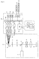
- FIG. 1 is a configuration diagram of this system. As shown in Fig. 1 , this system includes a main body of a microscope 10, a computer 20 connected thereto, and an input device 30 and a displaying device 40 connected thereto.
- the input device 30 is a mouse, a keyboard, and so on, and the displaying device 40 is an LCD or the like.
- a laser light source 11, a dichroic mirror 12, an optical scanner 13, an objective lens 14, a sample 15, an observation lens 16, a pinhole mask 17, a spectroscopic element 18, and a multichannel light detector 19 are placed.
- the sample 15 is labeled by plural types (for example, three types) of fluorescent reagents, and the multichannel light detector 19 has many (for example, 32) wavelength channels.
- the computer 20 incudes a CPU 23, a ROM 24 into which a basic operation program of the CPU 23 is written, a RAM used as a temporary storage means while the CPU 23 is operating, a hard disk drive 26 to save information for a long time.
- an interface circuit 27 interfacing the input device 30 and the displaying device 40, A/D converting circuits 21 1 , 21 2 , ..., 21 32 of the same number as wavelength channels of the multichannel light detector 19, and frame memories 22 1 22 2 ..., 22 32 of the same number as the A/D converting circuits.
- the frame memories 22 1 , 22 2 , ..., 22 32 , the hard disk drive 26, the CPU 23, the ROM 24, the RAM 25, the interface circuit 27 are connected via a bus 20B.
- An operation program of the CPU 23 necessary for this system is previously stored in the hard disk drive 26.
- Laser light (for example, having a wavelength of 488 nm) is emitted from the laser light source 11 of the main body of the microscope 10. This laser light is reflected by the dichroic mirror 12 and collected at a point on the sample 15 via the optical scanner 13 and the objective lens 14 in order. At the light collecting point, fluorescence (for example, having a wavelength of 510 nm to 550 nm) is generated, and when entering the dichroic mirror 12 via the objective lens 14 and the optical scanner 13 in order, the fluorescence is transmitted through this dichroic mirror 12 and enters the pinhole mask 17 via the observation lens 16.
- fluorescence for example, having a wavelength of 510 nm to 550 nm
- This pinhole mask 17 forms a conjugate relation with the sample 15 by the observation lens 16 and the objective lens 14 and has a function of letting only a necessary ray of light of the fluorescence generated on the sample 15 pass therethrough. As a result, a confocal effect of the main body of the microscope 10 can be obtained.
- the fluorescence which has passed through the pinhole mask 17 is separated into plural wavelength components. These respective wavelength components enter wavelength channels different from each other of the multichannel light detector 19 and detected independently and simultaneously.
- the respective wavelength channels (here, 32 wavelength channels) of the multichannel light detector 19 detect, for example, 32 kinds of wavelength components different in steps of 5 nm in a wavelength range from 510 nm to 550 nm. Respective signals outputted from the 32 wavelength channels are imported in parallel into the computer 20 and individually inputted to the frame memories 22 1 , 22 2 , ..., 22 32 via the A/D converting circuits 21 1 , 21 2 , ..., 21 32 .
- This multichannel light detector 19 and the optical scanner 13 are synchronously driven, and thereby the signals are repeatedly outputted from the multichannel light detector 19 during a period of two-dimensional scanning at the light collecting point on the sample 15.
- images of the respective wavelength channels of the sample 15 are gradually accumulated in the frame memories 22 1 , 22 2 , ..., 22 32 .
- the images (channels images D 1 , D 2 , ..., D 32 ) of the respective wavelength channels accumulated in the frame memories 22 1 , 22 2 , ..., 22 32 are read in an appropriate timing by the CPU 23, integrated into one spectral image F, and then stored in the hard disk drive 26.
- emission spectral data of the fluorescent reagents used for the sample 1 5 is previously stored.
- This emission spectral data is disclosed by manufactures of the fluorescent reagents or the like and loaded into the computer 20, for example, by the Internet, a storage medium, or the like.
- the operation of the CPU 23 after the spectral image F is acquired will be described.
- Fig. 2 is an operational flowchart of the CPU 23. As shown in Fig. 2 , after executing noise reducing processing constituted by normalizing processing (step S1), smoothing processing (step S2), and denormalizing processing (step S3), the CPU 23 executes unmixing processing (step S4), and displaying processing (step S5). These steps will be described below step by step.
- the CPU 23 refers to spectral curves of respective pixels from the spectral image F.
- Fig. 3(A) only spectral curves of some four pixels (a first pixel, second pixel, third pixel, fourth pixel) are shown.
- the horizontal axis of the spectral curve is a wavelength channel, and the vertical axis thereof is a brightness value.
- Brightness levels of the spectral curves of the respective pixels vary as shown in Fig. 3(A) .
- a brightness integral value A 1 of the spectral curve of the first pixel indicates a total brightness of the first pixel
- a brightness integral value A 2 of the spectral curve of the second pixel indicates a total brightness of the second pixel
- a brightness integral value A 3 of the spectral curve of the third pixel indicates a total brightness of the third pixel
- a brightness integral value A 4 of the spectral curve of the fourth pixel indicates a total brightness of the fourth pixel.
- any of the total brightnesses of the respective pixels becomes one in the spectral image F'. That is to say, brightness information of the spectral curves of the respective pixels is excluded from the spectral image F', and only shape information of the spectral curves of the respective pixels is maintained.
- respective wavelength components (channel images) of this spectral image F' are represented as D 1 ', D 2 ', ..., D 32 '.
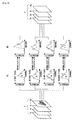
- the CPU 23 performs averaging filter processing on each of the above channel images D 1 ', D 2 ', ..., D 32 '. Therefore, each of the channel images D 1 ', D 2 ', ..., D 32 ' is smoothed in a spatial direction.
- a mask which is a computational mask
- This mask is put into the channel image D, and the brightness value of a target pixel located at the center of the opening of the mask is replaced with a brightness mean value of all the pixels in the opening.
- the CPU 23 denormalizes the spectral curves of the respective pixels constituting the spectral image F" such that their brightness integral values return to the brightness integral values before the normalization (see Fig. 3(A) ).
- a spectral image constituted by the above spectral curves after the denormalization is stored again as the spectral image F in the hard disk drive 26 as shown in the lower right of Fig. 4 .
- this spectral image F the brightness information of the spectral curves of the respective pixels is recovered by the denormalization. Besides, noise is removed from the shape information of the spectral curves of the respective pixels as described above. Accordingly, this spectral image F accurately represents the state of the sample 15.
- the CPU 23 reads the spectral image F and the emission spectral data of the fluorescent reagents from the hard disk drive 26.
- the emission spectral data represents emission spectral curves S 1 , S 2 , S 3 of the three types of fluorescent reagents (a first reagent, second reagent, third reagent).
- These emission spectral curves S 1 , S 2 , S 3 are each represented by a one-dimensional matrix such as shown in equation (1).
- an element S ij in equation (1) is a brightness value of an ith wavelength of a jth reagent.
- the CPU 23 performs unmixing processing of the spectral image F based on these emission spectral curves S 1 , S 2 , S 3 , and the unmixing is performed for each pixel of the spectral image F.
- a spectral curve f of some pixel included in the spectral image F is represented by a one-dimensional matrix such as shown in equation (2).
- An element f 1 is a brightness value of an ith wavelength channel of this pixel.
- Equation 3 f S 1 ⁇ p 1 + S 2 ⁇ p 2 + S 3 ⁇ p 3
- equation (3) is transformed as shown in equation (6).
- Equation 6 f S ⁇ P
- the CPU 23 can unmix this pixel by assigning information on the spectral curve f of this pixel and information on the emission spectral curve S to equation (6) and solving this equation for the contribution ratio P. Note, however, that since the number of wavelength channels (here, 32) is set larger than the number of types of fluorescent reagents (here, 3) as described above in this system, the CPU 23 applies a least squares method.
- the least squares method is to prepare equation (7) with consideration given to an error ⁇ in equation (6) and find the contribution ratio P such that a square value of the error ⁇ becomes minimum.
- Equation 7 f S ⁇ P + ⁇
- S T is a transposed matrix of S. Accordingly, the CPU unmixes this pixel by assigning the information on the spectral curve f of this pixel and the information on the emission spectral curve S to this equation (8). Then, the CPU 23 performs this unmixing on all the pixels of the spectral image F, respectively, and completes this step.
- the unmixing processing in this step is performed by the well-known least squares method, but since the spectral image F accurately represents the state of the sample 15 as described above, the accuracy of this unmixing processing is higher than that of the conventional one.
- the CPU 23 displays the information on the contribution ratios (contribution ratios of the respective fluorescent reagents to the respective pixels) found by the unmixing processing on the displaying device 40.
- the information on the contribution ratios may be displayed as numeric data, but in order to intuitively inform a user of it, it is desirable that the CPU 23 creates an unmixed image colored according to the contribution ratios and displays it.
- the computer 20 of this system removes noise from the spectral image prior to the unmixing processing, but this noise reducing processing does no damage to the brightness information of the spectral curves of the respective pixels as described above, so that the spectral image F which accurately represents the state of the sample 15 can be obtained.
- the accuracy of the unmixing processing by the computer 20, that is, the performance of this system is certainly improved.
- the standards of the normalization and the denormalization of the spectral curve are set to the brightness integral value of the spectral curve, but may be set to a brightness maximum value or a brightness intermediate value instead of the brightness integral value.
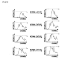
- Fig. 6 and Fig. 7 changes of the spectral curves when the standards of the normalization and the denormalization are set to the brightness maximum value are shown. Referring to Fig. 6 and Fig.
- peaks of the spectral curves of the respective pixels before the normalization are I 1 , I 2 , I 3 , I 4, but all become one after the normalization, and after the denormalization, return to the values I 1 , I 2 , I 3 , I 4 before the normalization.
- the averaging filter processing is applied, but instead of the averaging filter processing, a different spatial filter processing such as weighted averaging filter processing or a median-filter processing may be applied.
- the median-filter processing is to find a brightness intermediate value of all the pixels in the opening instead of calculating the brightness mean value thereof. It is desirable that the type of such filter processing be selected appropriately according to the type of the measurement noise generated in the main body of the microscope 10.
- the averaging filter processing is effective when nose is generated uniformly on the channel image, and the median-filter processing is effective when noise is generated suddenly on the channel image (salt-and-pepper noise).
- the start timing of the smoothing processing is after the normalization of the spectral curves of all the pixels, but it is also possible to normalize spectral curves of required pixels on a case-by-case basis while performing the smoothing processing.
- the operation program of the CPU 23 is previously stored in the hard disk drive 26, but part or all of the program may be installed into the computer 20 from outside via the Internet, a storage medium, or the like. Furthermore, in this system, each processing is executed by the computer 20, but part or all of the operations of the computer 20 may be executed by a device (control/image processing device) dedicated to the main body of the microscope 10.
- the main body of the microscope 10 of this system uses the multichannel light detector 19 to detect respective wavelength components of incident light, but instead of the multichannel light detector 19, a combination of one-channel light detector and a movable mask, a combination of plural one-channel light detectors and plural filters, or the like may be used. Note, however, that the use of the multichannel light detector 19 is advantageous in that space can be saved.
- the main body of the microscope 10 of this system is a fluorescent microscope which detects fluorescence generated on the sample 15, but may be a microscope which detects transmitted light or reflected light of light illuminating the sample 15. In this case, instead of the dichroic mirror 12, a beam splitter is used. Furthermore, the main body of the microscope 10 of this system is a confocal microscope which confocally detects light from the sample 15, but the function of this confocal detection may be omitted. In this case, the pinhole mask 17 becomes unnecessary.
- the main body of the microscope 10 of this system is a scanning microscope which optically scans the sample 15, but may be a non-scanning microscope. In this case, the optical scanner 13 becomes unnecessary. Namely, the present invention can be applied to various devices which perform spectral imaging.
Landscapes
- Physics & Mathematics (AREA)
- General Physics & Mathematics (AREA)
- Engineering & Computer Science (AREA)
- Health & Medical Sciences (AREA)
- Theoretical Computer Science (AREA)
- General Health & Medical Sciences (AREA)
- Immunology (AREA)
- Pathology (AREA)
- Life Sciences & Earth Sciences (AREA)
- Chemical & Material Sciences (AREA)
- Analytical Chemistry (AREA)
- Biochemistry (AREA)
- Multimedia (AREA)
- Signal Processing (AREA)
- Nuclear Medicine, Radiotherapy & Molecular Imaging (AREA)
- Mathematical Physics (AREA)
- Spectroscopy & Molecular Physics (AREA)
- Investigating, Analyzing Materials By Fluorescence Or Luminescence (AREA)
- Investigating Or Analysing Materials By Optical Means (AREA)
Abstract
Description
- The present invention relates to a spectral image processing method of processing a spectral image acquired by a microscope or the like and a computer-executable spectral image processing program. Further, the present invention relates to a spectral imaging system such as a spectral-imaging fluorescent laser microscope.
- In dynamic observation of an organism cell, a sample is labeled by a fluorescent material such as a fluorescent reagent or a fluorescent protein and observed by an optical microscope such as a fluorescent laser microscope in some cases. When plural fluorescent materials are used simultaneously, it is necessary to detect images of respective wavelength components (a spectral image).
However, when emission wavelengths of the plural fluorescent materials overlap, the images of these respective materials cannot be separated by the optical microscope, so that an analysis method of importing the spectral image detected by the microscope into a computer and separating (unmixing) it into the images of the respective materials becomes effective (seePatent Document 1 or the like). Incidentally, in this unmixing, emission spectral data of the respective materials disclosed by manufacturers of reagents and the like is used.
Patent Document 1: Timo Zimmermann, JensRietdorf, Rainer Pepperkok, "Spectral imaging and its applications in live cell microsopy", FEBS Letters 546(2003), P87-P92, 16 May 2003 - However, measurement noise is superimposed on a spectral image being actual measurement data due to instability of a light source of a microscope, electric noise of a light detecting element of the microscope, and so on, which exerts a strong influence on the accuracy of unmixing. In particular, when spectra of plural fluorescent reagents are similar, for example, when peak wavelengths are close to each other, the accuracy of unmixing becomes worse if the measurement noise is large.
- Among measures against this is a method of smoothing adjacent images by performing spatial filter processing, for example, averaging filter processing or median-filter processing, which is effective as a method of reducing noise. However, in such a method, brightnesses are also averaged, which causes a problem that spatial resolution is deteriorated and on a simple average, the influence of a pixel with a high brightness increases, so that the noise reduction is not necessarily sufficient.
- Hence, an object of the present invention is to provide a spectral image processing method capable of reducing noise without damaging necessary information as much as possible and a computer-executable spectral image processing program. Further, an object of the present invention is to provide a high-performance spectral imaging system.
- A spectral image processing method of the present invention is a spectral image processing method of performing processing on a spectral image of a specimen, including: a step of normalizing spectra (= spectral brightness curves) of respective pixels constituting the spectral image such that their brightness levels become equal; a step of smoothing the normalized spectra in spatial directions of the respective pixels; and a step of denormalization of multiplying spectra of the respective pixels obtained by the smoothing by either one of brightness levels of the pixels corresponding the spectra and values corresponding to the brightness levels.
- Incidentally, the normalization is performed such that brightness integral values of the spectra become equal, and the denormalization is performed such that the brightness integral values of the spectra return to values before the normalization.
Moreover, the normalization is performed such that brightness maximum values of the spectra become equal, and the denormalization is performed such that the brightness maximum values of the spectra return to values before the normalization. - Further, another spectral image processing method of the present invention includes an unmixing step of, based on a spectral image subjected to image processing using any spectral image processing method of the present invention and emission spectral information of plural materials contained in the specimen, separating and finding respective contributions of the plural materials to the spectral image.
Furthermore, a spectral image processing program of the present invention causes a computer to execute any spectral image processing method of the present invention. - Moreover, a spectral imaging system of the present invention includes: a spectral imaging unit which acquires a spectral image of a specimen; and a spectral image processing unit which imports the acquired spectral image and executes any spectral image processing method of the present invention.
- According to the present invention, a spectral image processing method capable of reducing noise without damaging necessary information as much as possible and a computer-executable spectral image processing program are realized. Further, according to the present invention, a high-performance spectral imaging system is realized.
-
-
Fig. 1 is a configuration diagram of a system of an embodiment; -
Fig. 2 is an operational flowchart of aCPU 23; -
Fig. 3 is a diagram explaining normalizing processing; -
Fig. 4 is a diagram explaining smoothing processing and denormalizing processing; -
Fig. 5 is a diagram showing examples of emission spectral curves S1, S2, S3 of fluorescent reagents; -
Fig. 6 is a diagram showing changes of spectral curves when the standard of normalization is set to a brightness maximum value; and -
Fig. 7 is a diagram showing changes of the spectral curves when the standard of denormalization is set to the brightness maximum value. - An embodiment of the present invention will be described. This embodiment is an embodiment of a spectral imaging fluorescent confocal laser microscope system.
First, the configuration of this system will be described.
Fig. 1 is a configuration diagram of this system. As shown inFig. 1 , this system includes a main body of amicroscope 10, acomputer 20 connected thereto, and aninput device 30 and a displayingdevice 40 connected thereto. Theinput device 30 is a mouse, a keyboard, and so on, and the displayingdevice 40 is an LCD or the like. - In the
main body 10, alaser light source 11, adichroic mirror 12, anoptical scanner 13, anobjective lens 14, asample 15, anobservation lens 16, apinhole mask 17, aspectroscopic element 18, and amultichannel light detector 19 are placed. Thesample 15 is labeled by plural types (for example, three types) of fluorescent reagents, and themultichannel light detector 19 has many (for example, 32) wavelength channels. - The
computer 20 incudes aCPU 23, aROM 24 into which a basic operation program of theCPU 23 is written, a RAM used as a temporary storage means while theCPU 23 is operating, ahard disk drive 26 to save information for a long time. aninterface circuit 27 interfacing theinput device 30 and the displayingdevice 40, A/D converting circuits 211, 212, ..., 2132 of the same number as wavelength channels of themultichannel light detector 19, and frame memories 221 222 ..., 2232 of the same number as the A/D converting circuits. The frame memories 221, 222, ..., 2232, thehard disk drive 26, theCPU 23, theROM 24, theRAM 25, theinterface circuit 27 are connected via abus 20B. An operation program of theCPU 23 necessary for this system is previously stored in thehard disk drive 26. - Laser light (for example, having a wavelength of 488 nm) is emitted from the
laser light source 11 of the main body of themicroscope 10. This laser light is reflected by thedichroic mirror 12 and collected at a point on thesample 15 via theoptical scanner 13 and theobjective lens 14 in order. At the light collecting point, fluorescence (for example, having a wavelength of 510 nm to 550 nm) is generated, and when entering thedichroic mirror 12 via theobjective lens 14 and theoptical scanner 13 in order, the fluorescence is transmitted through thisdichroic mirror 12 and enters thepinhole mask 17 via theobservation lens 16. Thispinhole mask 17 forms a conjugate relation with thesample 15 by theobservation lens 16 and theobjective lens 14 and has a function of letting only a necessary ray of light of the fluorescence generated on thesample 15 pass therethrough. As a result, a confocal effect of the main body of themicroscope 10 can be obtained. When entering the spectroscopic element 8, the fluorescence which has passed through thepinhole mask 17 is separated into plural wavelength components. These respective wavelength components enter wavelength channels different from each other of themultichannel light detector 19 and detected independently and simultaneously. - The respective wavelength channels (here, 32 wavelength channels) of the
multichannel light detector 19 detect, for example, 32 kinds of wavelength components different in steps of 5 nm in a wavelength range from 510 nm to 550 nm. Respective signals outputted from the 32 wavelength channels are imported in parallel into thecomputer 20 and individually inputted to the frame memories 221, 222, ..., 2232 via the A/D converting circuits 211, 212, ..., 2132. - This
multichannel light detector 19 and theoptical scanner 13 are synchronously driven, and thereby the signals are repeatedly outputted from themultichannel light detector 19 during a period of two-dimensional scanning at the light collecting point on thesample 15. At this time, images of the respective wavelength channels of thesample 15 are gradually accumulated in the frame memories 221, 222, ..., 2232. The images (channels images D1, D2, ..., D32) of the respective wavelength channels accumulated in the frame memories 221, 222, ..., 2232 are read in an appropriate timing by theCPU 23, integrated into one spectral image F, and then stored in thehard disk drive 26. - Incidentally, in the
hard disk drive 26 of thecomputer 20, in addition to this spectral image F, emission spectral data of the fluorescent reagents used for thesample 1 5 is previously stored. This emission spectral data is disclosed by manufactures of the fluorescent reagents or the like and loaded into thecomputer 20, for example, by the Internet, a storage medium, or the like.
Next, the operation of theCPU 23 after the spectral image F is acquired will be described. -
Fig. 2 is an operational flowchart of theCPU 23. As shown inFig. 2 , after executing noise reducing processing constituted by normalizing processing (step S1), smoothing processing (step S2), and denormalizing processing (step S3), theCPU 23 executes unmixing processing (step S4), and displaying processing (step S5). These steps will be described below step by step. - In this step, first, as shown in
Fig. 3(A) , theCPU 23 refers to spectral curves of respective pixels from the spectral image F. InFig. 3(A) , only spectral curves of some four pixels (a first pixel, second pixel, third pixel, fourth pixel) are shown. The horizontal axis of the spectral curve is a wavelength channel, and the vertical axis thereof is a brightness value. - Brightness levels of the spectral curves of the respective pixels vary as shown in
Fig. 3(A) . A brightness integral value A1 of the spectral curve of the first pixel indicates a total brightness of the first pixel, a brightness integral value A2 of the spectral curve of the second pixel indicates a total brightness of the second pixel, a brightness integral value A3 of the spectral curve of the third pixel indicates a total brightness of the third pixel, and a brightness integral value A4 of the spectral curve of the fourth pixel indicates a total brightness of the fourth pixel. - Further, as shown in
Fig. 3(A) , shapes of the spectral curves vary among the respective pixels. Between close pixels, there is a high possibility that rough shapes of the spectral curves are similar, but fine shapes of the spectral curves differ from each other even if the pixels are close since random measurement noise is superimposed.
Then, as shown inFig. 3(B) , theCPU 23 normalizes the spectral curves of the respective pixels such that their brightness integral values A become one. In the normalization of each spectral curve, it is only required to multiply brightness values of the respective wavelength channels of the spectral curve by a normalizing coefficient = (1/current brightness integral value). - When a spectral image F' constituted by the normalized spectral curves is referred to here as shown at the right side of
Fig. 3 , any of the total brightnesses of the respective pixels becomes one in the spectral image F'. That is to say, brightness information of the spectral curves of the respective pixels is excluded from the spectral image F', and only shape information of the spectral curves of the respective pixels is maintained. Hereinafter, respective wavelength components (channel images) of this spectral image F' are represented as D1', D2', ..., D32'. - In this step, as shown in
Fig. 4(A) , theCPU 23 performs averaging filter processing on each of the above channel images D1', D2', ..., D32'. Therefore, each of the channel images D1', D2', ..., D32' is smoothed in a spatial direction.
In the averaging filter processing for the channel image D', a mask (which is a computational mask), for example, having an opening of three pixels high by three pixels wide is used. This mask is put into the channel image D, and the brightness value of a target pixel located at the center of the opening of the mask is replaced with a brightness mean value of all the pixels in the opening. By repeatedly performing this processing while shifting a mask position on the channel image D', processing of the whole area of the image is completed. - Here, if the respective channel images after the smoothing are represented as D1", D2", ..., D32" as shown in the lower left of
Fig. 4 and a spectral image F" constituted by these channel images D1", D2", ..., D32" is referred to, in the spectral image F", as shown inFig. 4(B) , shapes of the spectral curves of the respective pixels become smooth. This is because the shapes of the spectral curves of the respective pixels are influenced by the shapes of the spectral curves of their adjacent pixels by the smoothing. This indicates that noise is removed from the shape information of the spectral curves of the respective pixels. - In this step, as shown in
Fig. 4(C) , theCPU 23 denormalizes the spectral curves of the respective pixels constituting the spectral image F" such that their brightness integral values return to the brightness integral values before the normalization (seeFig. 3(A) ). Concerning the spectral curve of the first pixel, it is denormalized such that its brightness integral value returns to the value A1 before the normalization, concerning the spectral curve of the second pixel, it is denormalized such that its brightness integral value returns to the value A2 before the normalization, concerning the spectral curve of the third pixel, it is denormalized such that its brightness integral value returns to the value A3 before the normalization, and concerning the spectral curve of the fourth pixel, it is denormalized such that its brightness integral value returns to the value A4 before the normalization. In the denormalization of each spectral curve, it is only required to multiply brightness values of the respective wavelength channels of the spectral curve by an denormalizing coefficient = (brightness integral value before normalization/current brightness integral value). - A spectral image constituted by the above spectral curves after the denormalization is stored again as the spectral image F in the
hard disk drive 26 as shown in the lower right ofFig. 4 .
In this spectral image F, the brightness information of the spectral curves of the respective pixels is recovered by the denormalization. Besides, noise is removed from the shape information of the spectral curves of the respective pixels as described above. Accordingly, this spectral image F accurately represents the state of thesample 15. - In this step, first, the
CPU 23 reads the spectral image F and the emission spectral data of the fluorescent reagents from thehard disk drive 26.
As shown inFigs. 5(A), (B), (C) , the emission spectral data represents emission spectral curves S1, S2, S3 of the three types of fluorescent reagents (a first reagent, second reagent, third reagent). These emission spectral curves S1, S2, S3 are each represented by a one-dimensional matrix such as shown in equation (1). -

- Note that an element Sij in equation (1) is a brightness value of an ith wavelength of a jth reagent. The number of elements in a wavelength direction of this matrix is set to 32 to match the data amount in a wavelength direction of the spectral image F (= the number of wavelength channels of the multichannel light detector 19).
TheCPU 23 performs unmixing processing of the spectral image F based on these emission spectral curves S1, S2, S3, and the unmixing is performed for each pixel of the spectral image F. - A spectral curve f of some pixel included in the spectral image F is represented by a one-dimensional matrix such as shown in equation (2). An element f1 is a brightness value of an ith wavelength channel of this pixel.
-

- Accordingly, if the contribution ratio of the first reagent to this pixel is taken as p1, the contribution ratio of the second reagent thereto is taken as p2, and the contribution ratio of the third reagent thereto is taken as p3, the spectral curve f of this pixel is represented by equation (3).
-

- Further, if the respective emission spectral curves of the three types of fluorescent reagents are brought together and represented by one matrix S as shown in equation (4), and the respective contribution ratios of the three types of fluorescent reagents are brought together and represented by one matrix P as shown in equation (5), equation (3) is transformed as shown in equation (6).
-

-

-

- Hence, the
CPU 23 can unmix this pixel by assigning information on the spectral curve f of this pixel and information on the emission spectral curve S to equation (6) and solving this equation for the contribution ratio P.
Note, however, that since the number of wavelength channels (here, 32) is set larger than the number of types of fluorescent reagents (here, 3) as described above in this system, theCPU 23 applies a least squares method. - The least squares method is to prepare equation (7) with consideration given to an error ε in equation (6) and find the contribution ratio P such that a square value of the error ε becomes minimum.
-

- An equation to calculate the contribution ratio P by this least squares method is shown as in equation (8).
-

- Note that ST is a transposed matrix of S.
Accordingly, the CPU unmixes this pixel by assigning the information on the spectral curve f of this pixel and the information on the emission spectral curve S to this equation (8). Then, theCPU 23 performs this unmixing on all the pixels of the spectral image F, respectively, and completes this step. - As just described, the unmixing processing in this step is performed by the well-known least squares method, but since the spectral image F accurately represents the state of the
sample 15 as described above, the accuracy of this unmixing processing is higher than that of the conventional one. - In this step, the
CPU 23 displays the information on the contribution ratios (contribution ratios of the respective fluorescent reagents to the respective pixels) found by the unmixing processing on the displayingdevice 40. The information on the contribution ratios may be displayed as numeric data, but in order to intuitively inform a user of it, it is desirable that theCPU 23 creates an unmixed image colored according to the contribution ratios and displays it. - As described above, the
computer 20 of this system removes noise from the spectral image prior to the unmixing processing, but this noise reducing processing does no damage to the brightness information of the spectral curves of the respective pixels as described above, so that the spectral image F which accurately represents the state of thesample 15 can be obtained. Hence, the accuracy of the unmixing processing by thecomputer 20, that is, the performance of this system is certainly improved. - Incidentally, in the noise reducing processing (steps S1 to S3) of this system, the standards of the normalization and the denormalization of the spectral curve are set to the brightness integral value of the spectral curve, but may be set to a brightness maximum value or a brightness intermediate value instead of the brightness integral value.
InFig. 6 andFig. 7 , changes of the spectral curves when the standards of the normalization and the denormalization are set to the brightness maximum value are shown. Referring toFig. 6 andFig. 7 , it can be seen that peaks of the spectral curves of the respective pixels before the normalization are I1, I2, I3, I4, but all become one after the normalization, and after the denormalization, return to the values I1, I2, I3, I4 before the normalization. - Further, in the smoothing processing (step S2) of this system, the averaging filter processing is applied, but instead of the averaging filter processing, a different spatial filter processing such as weighted averaging filter processing or a median-filter processing may be applied. For reference's sake, the median-filter processing is to find a brightness intermediate value of all the pixels in the opening instead of calculating the brightness mean value thereof. It is desirable that the type of such filter processing be selected appropriately according to the type of the measurement noise generated in the main body of the
microscope 10. For reference's sake, the averaging filter processing is effective when nose is generated uniformly on the channel image, and the median-filter processing is effective when noise is generated suddenly on the channel image (salt-and-pepper noise). - Furthermore, in the smoothing processing (step S2) of this system, the size of the mask (size of a filter) is 3 pixels x 3 pixels = 9 pixels, but may be changed to a different size. It is desirable that this size be selected appropriately according to the type of the measurement noise generated in the main body of the
microscope 10.
Moreover, in the noise reducing processing (steps S1 to S3) of this system, the start timing of the smoothing processing is after the normalization of the spectral curves of all the pixels, but it is also possible to normalize spectral curves of required pixels on a case-by-case basis while performing the smoothing processing. - Further, in this system, the operation program of the
CPU 23 is previously stored in thehard disk drive 26, but part or all of the program may be installed into thecomputer 20 from outside via the Internet, a storage medium, or the like.
Furthermore, in this system, each processing is executed by thecomputer 20, but part or all of the operations of thecomputer 20 may be executed by a device (control/image processing device) dedicated to the main body of themicroscope 10. - Moreover, the main body of the
microscope 10 of this system uses the multichannellight detector 19 to detect respective wavelength components of incident light, but instead of the multichannellight detector 19, a combination of one-channel light detector and a movable mask, a combination of plural one-channel light detectors and plural filters, or the like may be used. Note, however, that the use of the multichannellight detector 19 is advantageous in that space can be saved. - Further, the main body of the
microscope 10 of this system is a fluorescent microscope which detects fluorescence generated on thesample 15, but may be a microscope which detects transmitted light or reflected light of light illuminating thesample 15. In this case, instead of thedichroic mirror 12, a beam splitter is used.
Furthermore, the main body of themicroscope 10 of this system is a confocal microscope which confocally detects light from thesample 15, but the function of this confocal detection may be omitted. In this case, thepinhole mask 17 becomes unnecessary. - Additionally, the main body of the
microscope 10 of this system is a scanning microscope which optically scans thesample 15, but may be a non-scanning microscope. In this case, theoptical scanner 13 becomes unnecessary.
Namely, the present invention can be applied to various devices which perform spectral imaging.
Claims (6)
- A spectral image processing method of performing processing on a spectral image of a specimen, comprising:a step of normalizing spectra (= spectral brightness curves) of respective pixels constituting said spectral image such that their brightness levels become equal;a step of smoothing said normalized spectra in spatial directions of said respective pixels; anda step of denormalization of multiplying spectra of the respective pixels obtained by said smoothing by either one of brightness levels of the pixels corresponding the spectra and values corresponding to the brightness levels.
- The spectral image processing method according to claim 1, wherein
said normalization is performed such that brightness integral values of said spectra become equal, and
said denormalization is performed such that the brightness integral values of said spectra return to values before said normalization. - The spectral image processing method according to claim 1, wherein
said normalization is performed such that brightness maximum values of said spectra become equal, and
said denormalization is performed such that the brightness maximum values of said spectra return to values before said normalization. - A spectral image processing method, comprising
an unmixing step of, based on a spectral image subjected to image processing using the spectral image processing method according to any one of claim 1 to claim 3 and emission spectral information of plural materials contained in said specimen, separating and finding respective contributions of said plural materials to said spectral image. - A computer-executable spectral image processing program causing a computer to execute a spectral image processing method according to any one of claim 1 to claim 4.
- A spectral imaging system, comprising:a spectral imaging unit which acquires a spectral image of a specimen; anda spectral image processing unit which imports said acquired spectral image and executes the spectral image processing method according to any one of claim 1 to claim 4.
Applications Claiming Priority (2)
| Application Number | Priority Date | Filing Date | Title |
|---|---|---|---|
| JP2006046508 | 2006-02-23 | ||
| PCT/JP2007/051698 WO2007097170A1 (en) | 2006-02-23 | 2007-02-01 | Spectrum image processing method, computer-executable spectrum image processing program, and spectrum imaging system |
Publications (3)
| Publication Number | Publication Date |
|---|---|
| EP1988383A1 true EP1988383A1 (en) | 2008-11-05 |
| EP1988383A4 EP1988383A4 (en) | 2016-08-24 |
| EP1988383B1 EP1988383B1 (en) | 2020-09-30 |
Family
ID=38437209
Family Applications (1)
| Application Number | Title | Priority Date | Filing Date |
|---|---|---|---|
| EP07707884.8A Active EP1988383B1 (en) | 2006-02-23 | 2007-02-01 | Spectrum image processing method, computer-executable spectrum image processing program, and spectrum imaging system |
Country Status (4)
| Country | Link |
|---|---|
| US (1) | US8055035B2 (en) |
| EP (1) | EP1988383B1 (en) |
| JP (1) | JP4826586B2 (en) |
| WO (1) | WO2007097170A1 (en) |
Families Citing this family (20)
| Publication number | Priority date | Publication date | Assignee | Title |
|---|---|---|---|---|
| US8045153B2 (en) * | 2006-02-23 | 2011-10-25 | Nikon Corporation | Spectral image processing method, spectral image processing program, and spectral imaging system |
| EP1988383B1 (en) | 2006-02-23 | 2020-09-30 | Nikon Corporation | Spectrum image processing method, computer-executable spectrum image processing program, and spectrum imaging system |
| CA3162577C (en) | 2008-05-20 | 2023-09-26 | University Health Network | Device and method for fluorescence-based imaging and monitoring |
| JP2010102196A (en) * | 2008-10-24 | 2010-05-06 | Olympus Corp | Automatic adjustment method for microscope image, and microscope system |
| CA2762886A1 (en) * | 2009-05-22 | 2010-11-25 | British Columbia Cancer Agency Branch | Selective excitation light fluorescence imaging methods and apparatus |
| JP5506443B2 (en) * | 2010-02-10 | 2014-05-28 | オリンパス株式会社 | Fluorescence observation equipment |
| JP5721959B2 (en) * | 2010-03-16 | 2015-05-20 | オリンパス株式会社 | Fluorescence endoscope device |
| CN102074008B (en) * | 2011-01-05 | 2013-02-06 | 哈尔滨工程大学 | A Fully Constrained Least Squares Linear Spectral Hybrid Analysis Method for Hyperspectral Images |
| JP6392785B2 (en) | 2013-01-31 | 2018-09-19 | ベンタナ メディカル システムズ, インコーポレイテッド | System and method for calibrating, configuring, and determining validity of an imaging device or system for multiple tissue assays |
| CA2931216A1 (en) * | 2013-12-31 | 2015-07-09 | Ventana Medical Systems, Inc. | Systems and methods for spectral unmixing of microscopic images using pixel grouping |
| JP5839077B2 (en) * | 2014-05-02 | 2016-01-06 | 株式会社ニコン | Laser excited fluorescence microscope |
| WO2016011534A1 (en) | 2014-07-24 | 2016-01-28 | University Health Network | Collection and analysis of data for diagnostic purposes |
| EP3166072A1 (en) * | 2015-11-06 | 2017-05-10 | Thomson Licensing | Method for denoising an image and apparatus for denoising an image |
| CN110785654A (en) * | 2017-06-28 | 2020-02-11 | 文塔纳医疗系统公司 | System level calibration |
| US11480513B2 (en) * | 2017-09-08 | 2022-10-25 | Sony Corporation | Fine particle measurement apparatus, information processing apparatus, and information processing method |
| CN113785187B (en) | 2019-03-22 | 2025-01-28 | 贝克顿·迪金森公司 | Spectral unmixing of fluorescence imaging using radiofrequency multiplexed excitation data |
| JP2021143988A (en) * | 2020-03-13 | 2021-09-24 | ソニーグループ株式会社 | Particle analysis system and particle analysis method |
| CN113175994B (en) * | 2021-03-26 | 2023-04-07 | 上海卫星工程研究所 | Spectral noise analysis method, system and medium for satellite-borne Fourier transform infrared spectrometer |
| RU2767607C1 (en) * | 2021-04-23 | 2022-03-18 | Российская Федерация, от имени которой выступает ФОНД ПЕРСПЕКТИВНЫХ ИССЛЕДОВАНИЙ | Method for generating signals of multispectral images |
| CN115409735A (en) * | 2022-09-05 | 2022-11-29 | 航天宏图信息技术股份有限公司 | Filtering method and device for InSAR interference image |
Family Cites Families (32)
| Publication number | Priority date | Publication date | Assignee | Title |
|---|---|---|---|---|
| US5798262A (en) * | 1991-02-22 | 1998-08-25 | Applied Spectral Imaging Ltd. | Method for chromosomes classification |
| US5991456A (en) * | 1996-05-29 | 1999-11-23 | Science And Technology Corporation | Method of improving a digital image |
| US6015667A (en) * | 1996-06-03 | 2000-01-18 | The Perkin-Emer Corporation | Multicomponent analysis method including the determination of a statistical confidence interval |
| JP3783815B2 (en) * | 1997-12-18 | 2006-06-07 | 株式会社リコー | Image processing device |
| US6341257B1 (en) * | 1999-03-04 | 2002-01-22 | Sandia Corporation | Hybrid least squares multivariate spectral analysis methods |
| US6415233B1 (en) * | 1999-03-04 | 2002-07-02 | Sandia Corporation | Classical least squares multivariate spectral analysis |
| US6750964B2 (en) * | 1999-08-06 | 2004-06-15 | Cambridge Research And Instrumentation, Inc. | Spectral imaging methods and systems |
| US6888963B2 (en) * | 2000-07-18 | 2005-05-03 | Matsushita Electric Industrial Co., Ltd. | Image processing apparatus and image processing method |
| US6894699B2 (en) * | 2000-07-21 | 2005-05-17 | Mitsubishi Denki Kabushiki Kaisha | Image display device employing selective or asymmetrical smoothing |
| JP3815188B2 (en) * | 2000-07-21 | 2006-08-30 | 三菱電機株式会社 | Image display device and image display method |
| US20020047907A1 (en) * | 2000-08-30 | 2002-04-25 | Nikon Corporation | Image processing apparatus and storage medium for storing image processing program |
| JP2002152762A (en) * | 2000-08-30 | 2002-05-24 | Nikon Corp | Image processing apparatus and recording medium storing image processing program |
| JP3690271B2 (en) * | 2000-11-29 | 2005-08-31 | 株式会社島津製作所 | Method for obtaining matrix values for nucleic acid sequencing |
| US20040064299A1 (en) * | 2001-08-10 | 2004-04-01 | Howard Mark | Automated system and method for spectroscopic analysis |
| JP2003083894A (en) | 2001-09-14 | 2003-03-19 | Sumitomo Electric Ind Ltd | Fluorescence value correction method, fluorescence value correction device, fluorescence value correction program, and recording medium storing the fluorescence value correction program |
| DE10222779A1 (en) * | 2002-05-16 | 2004-03-04 | Carl Zeiss Jena Gmbh | Method and arrangement for examining samples |
| US6763308B2 (en) * | 2002-05-28 | 2004-07-13 | Sas Institute Inc. | Statistical outlier detection for gene expression microarray data |
| US6906859B2 (en) * | 2002-06-05 | 2005-06-14 | Nikon Corporation | Epi-illumination apparatus for fluorescent observation and fluorescence microscope having the same |
| US7480083B2 (en) * | 2002-07-30 | 2009-01-20 | Canon Kabushiki Kaisha | Image processing system, apparatus, and method, and color reproduction method |
| US20050233307A1 (en) * | 2002-09-12 | 2005-10-20 | Kyle Gee | Site-specific labeling of affinity tags in fusion proteins |
| JP3903000B2 (en) * | 2002-11-14 | 2007-04-11 | アークレイ株式会社 | Measuring apparatus, fluorescence measuring apparatus and fluorescence measuring method |
| US7471831B2 (en) * | 2003-01-16 | 2008-12-30 | California Institute Of Technology | High throughput reconfigurable data analysis system |
| US7283684B1 (en) * | 2003-05-20 | 2007-10-16 | Sandia Corporation | Spectral compression algorithms for the analysis of very large multivariate images |
| WO2005013622A1 (en) * | 2003-06-30 | 2005-02-10 | Nikon Corporation | Image processing device for processing image having different color components arranged, image processing program, electronic camera, and image processing method |
| US7321791B2 (en) * | 2003-09-23 | 2008-01-22 | Cambridge Research And Instrumentation, Inc. | Spectral imaging of deep tissue |
| US7426026B2 (en) | 2003-10-10 | 2008-09-16 | Hamamatsu Photonics K.K. | Method and system for measuring the concentrations of fluorescent dyes |
| JP4021414B2 (en) * | 2003-11-26 | 2007-12-12 | オリンパス株式会社 | Spectral deconvolution method and Spectral blind deconvolution method |
| US20050285023A1 (en) * | 2004-06-23 | 2005-12-29 | Lambda Solutions, Inc. | Automatic background removal for input data |
| US7457472B2 (en) * | 2005-03-31 | 2008-11-25 | Euclid Discoveries, Llc | Apparatus and method for processing video data |
| WO2006081547A1 (en) * | 2005-01-27 | 2006-08-03 | Cambridge Research And Instrumentation, Inc. | Classifying image features |
| US20070099535A1 (en) * | 2005-11-03 | 2007-05-03 | Riebersal Michael A | Water throwing toy |
| EP1988383B1 (en) | 2006-02-23 | 2020-09-30 | Nikon Corporation | Spectrum image processing method, computer-executable spectrum image processing program, and spectrum imaging system |
-
2007
- 2007-02-01 EP EP07707884.8A patent/EP1988383B1/en active Active
- 2007-02-01 JP JP2007526098A patent/JP4826586B2/en active Active
- 2007-02-01 WO PCT/JP2007/051698 patent/WO2007097170A1/en not_active Ceased
- 2007-02-01 US US11/913,281 patent/US8055035B2/en active Active
Non-Patent Citations (1)
| Title |
|---|
| See references of WO2007097170A1 * |
Also Published As
| Publication number | Publication date |
|---|---|
| EP1988383A4 (en) | 2016-08-24 |
| US8055035B2 (en) | 2011-11-08 |
| JP4826586B2 (en) | 2011-11-30 |
| WO2007097170A1 (en) | 2007-08-30 |
| US20090080722A1 (en) | 2009-03-26 |
| EP1988383B1 (en) | 2020-09-30 |
| JPWO2007097170A1 (en) | 2009-07-09 |
Similar Documents
| Publication | Publication Date | Title |
|---|---|---|
| US8055035B2 (en) | Spectral image processing method, computer-executable spectral image processing program, and spectral imaging system | |
| US8045153B2 (en) | Spectral image processing method, spectral image processing program, and spectral imaging system | |
| US7420674B2 (en) | Method and arrangement for analyzing samples | |
| Bolte et al. | A guided tour into subcellular colocalization analysis in light microscopy | |
| US8126267B2 (en) | Methods and apparatuses for analyzing digital images to automatically select regions of interest thereof | |
| US7009699B2 (en) | Method for investigating a sample | |
| US20200003990A1 (en) | Methods, systems and devices for automatically focusing a microscope on a substrate | |
| US20090040517A1 (en) | Raman difference spectra based disease classification | |
| JP6605716B2 (en) | Automatic staining detection in pathological bright field images | |
| US8160331B2 (en) | Image processing apparatus and computer program product | |
| JP5228729B2 (en) | Spectral image processing method, spectral image processing program, and spectral imaging system | |
| US20230175963A1 (en) | Method of analyzing a mixed fluorescence response of a plurality of fluorophores, fluorescence analyzer, fluorescence microscope and computer program | |
| US7337066B2 (en) | System and method for automated baseline correction for Raman spectra | |
| US8811728B2 (en) | Image processing apparatus and computer program product | |
| CN117546007A (en) | Information processing device, biological sample observation system, and image generation method | |
| EP4121743B1 (en) | Fluorescence microscope and method for imaging an object | |
| EP3471393B1 (en) | Data recovery device, microscope system, and data recovery method | |
| EP1947441A2 (en) | Apparatus for determining positions of objects contained in a sample | |
| US12487441B2 (en) | Systems and methods for fluorescence microscopy channel crosstalk mitigation | |
| US8892400B2 (en) | Method for evaluating fluorescence correlation spectroscopy measurement data | |
| Schidorsky et al. | Synergizing superresolution optical fluctuation imaging with single molecule localization microscopy | |
| US20050109949A1 (en) | Method and system for the analysis of co-localizations | |
| US12510480B2 (en) | Systems and methods for fluorescence microscopy channel crosstalk mitigation | |
| Kossonou et al. | Development of a multispectral microscopy platform using laser diode illumination for effective and automatic label-free Plasmodium falciparum detection | |
| US20230368549A1 (en) | Automatic image quality and feature classification method |
Legal Events
| Date | Code | Title | Description |
|---|---|---|---|
| PUAI | Public reference made under article 153(3) epc to a published international application that has entered the european phase |
Free format text: ORIGINAL CODE: 0009012 |
|
| 17P | Request for examination filed |
Effective date: 20071030 |
|
| AK | Designated contracting states |
Kind code of ref document: A1 Designated state(s): AT BE BG CH CY CZ DE DK EE ES FI FR GB GR HU IE IS IT LI LT LU LV MC NL PL PT RO SE SI SK TR |
|
| RAP1 | Party data changed (applicant data changed or rights of an application transferred) |
Owner name: NIKON CORPORATION |
|
| DAX | Request for extension of the european patent (deleted) | ||
| RAP1 | Party data changed (applicant data changed or rights of an application transferred) |
Owner name: NIKON CORPORATION |
|
| REG | Reference to a national code |
Ref country code: DE Ref legal event code: R079 Ref document number: 602007060669 Country of ref document: DE Free format text: PREVIOUS MAIN CLASS: G01N0021640000 Ipc: G06T0005500000 |
|
| RA4 | Supplementary search report drawn up and despatched (corrected) |
Effective date: 20160727 |
|
| RIC1 | Information provided on ipc code assigned before grant |
Ipc: G01N 21/64 20060101ALI20160721BHEP Ipc: G01N 21/27 20060101ALI20160721BHEP Ipc: G06T 5/00 20060101ALI20160721BHEP Ipc: H04N 1/409 20060101ALI20160721BHEP Ipc: G06T 5/50 20060101AFI20160721BHEP |
|
| STAA | Information on the status of an ep patent application or granted ep patent |
Free format text: STATUS: EXAMINATION IS IN PROGRESS |
|
| 17Q | First examination report despatched |
Effective date: 20181004 |
|
| GRAP | Despatch of communication of intention to grant a patent |
Free format text: ORIGINAL CODE: EPIDOSNIGR1 |
|
| STAA | Information on the status of an ep patent application or granted ep patent |
Free format text: STATUS: GRANT OF PATENT IS INTENDED |
|
| INTG | Intention to grant announced |
Effective date: 20200416 |
|
| GRAS | Grant fee paid |
Free format text: ORIGINAL CODE: EPIDOSNIGR3 |
|
| GRAA | (expected) grant |
Free format text: ORIGINAL CODE: 0009210 |
|
| STAA | Information on the status of an ep patent application or granted ep patent |
Free format text: STATUS: THE PATENT HAS BEEN GRANTED |
|
| AK | Designated contracting states |
Kind code of ref document: B1 Designated state(s): AT BE BG CH CY CZ DE DK EE ES FI FR GB GR HU IE IS IT LI LT LU LV MC NL PL PT RO SE SI SK TR |
|
| REG | Reference to a national code |
Ref country code: GB Ref legal event code: FG4D Ref country code: CH Ref legal event code: EP |
|
| REG | Reference to a national code |
Ref country code: AT Ref legal event code: REF Ref document number: 1319580 Country of ref document: AT Kind code of ref document: T Effective date: 20201015 Ref country code: DE Ref legal event code: R096 Ref document number: 602007060669 Country of ref document: DE |
|
| REG | Reference to a national code |
Ref country code: IE Ref legal event code: FG4D |
|
| PG25 | Lapsed in a contracting state [announced via postgrant information from national office to epo] |
Ref country code: SE Free format text: LAPSE BECAUSE OF FAILURE TO SUBMIT A TRANSLATION OF THE DESCRIPTION OR TO PAY THE FEE WITHIN THE PRESCRIBED TIME-LIMIT Effective date: 20200930 Ref country code: BG Free format text: LAPSE BECAUSE OF FAILURE TO SUBMIT A TRANSLATION OF THE DESCRIPTION OR TO PAY THE FEE WITHIN THE PRESCRIBED TIME-LIMIT Effective date: 20201230 Ref country code: GR Free format text: LAPSE BECAUSE OF FAILURE TO SUBMIT A TRANSLATION OF THE DESCRIPTION OR TO PAY THE FEE WITHIN THE PRESCRIBED TIME-LIMIT Effective date: 20201231 Ref country code: FI Free format text: LAPSE BECAUSE OF FAILURE TO SUBMIT A TRANSLATION OF THE DESCRIPTION OR TO PAY THE FEE WITHIN THE PRESCRIBED TIME-LIMIT Effective date: 20200930 |
|
| REG | Reference to a national code |
Ref country code: AT Ref legal event code: MK05 Ref document number: 1319580 Country of ref document: AT Kind code of ref document: T Effective date: 20200930 |
|
| PG25 | Lapsed in a contracting state [announced via postgrant information from national office to epo] |
Ref country code: LV Free format text: LAPSE BECAUSE OF FAILURE TO SUBMIT A TRANSLATION OF THE DESCRIPTION OR TO PAY THE FEE WITHIN THE PRESCRIBED TIME-LIMIT Effective date: 20200930 |
|
| REG | Reference to a national code |
Ref country code: NL Ref legal event code: MP Effective date: 20200930 |
|
| REG | Reference to a national code |
Ref country code: LT Ref legal event code: MG4D |
|
| PG25 | Lapsed in a contracting state [announced via postgrant information from national office to epo] |
Ref country code: RO Free format text: LAPSE BECAUSE OF FAILURE TO SUBMIT A TRANSLATION OF THE DESCRIPTION OR TO PAY THE FEE WITHIN THE PRESCRIBED TIME-LIMIT Effective date: 20200930 Ref country code: PT Free format text: LAPSE BECAUSE OF FAILURE TO SUBMIT A TRANSLATION OF THE DESCRIPTION OR TO PAY THE FEE WITHIN THE PRESCRIBED TIME-LIMIT Effective date: 20210201 Ref country code: LT Free format text: LAPSE BECAUSE OF FAILURE TO SUBMIT A TRANSLATION OF THE DESCRIPTION OR TO PAY THE FEE WITHIN THE PRESCRIBED TIME-LIMIT Effective date: 20200930 Ref country code: NL Free format text: LAPSE BECAUSE OF FAILURE TO SUBMIT A TRANSLATION OF THE DESCRIPTION OR TO PAY THE FEE WITHIN THE PRESCRIBED TIME-LIMIT Effective date: 20200930 Ref country code: EE Free format text: LAPSE BECAUSE OF FAILURE TO SUBMIT A TRANSLATION OF THE DESCRIPTION OR TO PAY THE FEE WITHIN THE PRESCRIBED TIME-LIMIT Effective date: 20200930 Ref country code: CZ Free format text: LAPSE BECAUSE OF FAILURE TO SUBMIT A TRANSLATION OF THE DESCRIPTION OR TO PAY THE FEE WITHIN THE PRESCRIBED TIME-LIMIT Effective date: 20200930 |
|
| PG25 | Lapsed in a contracting state [announced via postgrant information from national office to epo] |
Ref country code: PL Free format text: LAPSE BECAUSE OF FAILURE TO SUBMIT A TRANSLATION OF THE DESCRIPTION OR TO PAY THE FEE WITHIN THE PRESCRIBED TIME-LIMIT Effective date: 20200930 Ref country code: AT Free format text: LAPSE BECAUSE OF FAILURE TO SUBMIT A TRANSLATION OF THE DESCRIPTION OR TO PAY THE FEE WITHIN THE PRESCRIBED TIME-LIMIT Effective date: 20200930 Ref country code: IS Free format text: LAPSE BECAUSE OF FAILURE TO SUBMIT A TRANSLATION OF THE DESCRIPTION OR TO PAY THE FEE WITHIN THE PRESCRIBED TIME-LIMIT Effective date: 20210130 Ref country code: ES Free format text: LAPSE BECAUSE OF FAILURE TO SUBMIT A TRANSLATION OF THE DESCRIPTION OR TO PAY THE FEE WITHIN THE PRESCRIBED TIME-LIMIT Effective date: 20200930 |
|
| PG25 | Lapsed in a contracting state [announced via postgrant information from national office to epo] |
Ref country code: SK Free format text: LAPSE BECAUSE OF FAILURE TO SUBMIT A TRANSLATION OF THE DESCRIPTION OR TO PAY THE FEE WITHIN THE PRESCRIBED TIME-LIMIT Effective date: 20200930 |
|
| REG | Reference to a national code |
Ref country code: DE Ref legal event code: R097 Ref document number: 602007060669 Country of ref document: DE |
|
| PLBE | No opposition filed within time limit |
Free format text: ORIGINAL CODE: 0009261 |
|
| STAA | Information on the status of an ep patent application or granted ep patent |
Free format text: STATUS: NO OPPOSITION FILED WITHIN TIME LIMIT |
|
| PG25 | Lapsed in a contracting state [announced via postgrant information from national office to epo] |
Ref country code: DK Free format text: LAPSE BECAUSE OF FAILURE TO SUBMIT A TRANSLATION OF THE DESCRIPTION OR TO PAY THE FEE WITHIN THE PRESCRIBED TIME-LIMIT Effective date: 20200930 |
|
| 26N | No opposition filed |
Effective date: 20210701 |
|
| PG25 | Lapsed in a contracting state [announced via postgrant information from national office to epo] |
Ref country code: MC Free format text: LAPSE BECAUSE OF FAILURE TO SUBMIT A TRANSLATION OF THE DESCRIPTION OR TO PAY THE FEE WITHIN THE PRESCRIBED TIME-LIMIT Effective date: 20200930 |
|
| GBPC | Gb: european patent ceased through non-payment of renewal fee |
Effective date: 20210201 |
|
| REG | Reference to a national code |
Ref country code: BE Ref legal event code: MM Effective date: 20210228 |
|
| PG25 | Lapsed in a contracting state [announced via postgrant information from national office to epo] |
Ref country code: CH Free format text: LAPSE BECAUSE OF NON-PAYMENT OF DUE FEES Effective date: 20210228 Ref country code: IT Free format text: LAPSE BECAUSE OF FAILURE TO SUBMIT A TRANSLATION OF THE DESCRIPTION OR TO PAY THE FEE WITHIN THE PRESCRIBED TIME-LIMIT Effective date: 20200930 Ref country code: LU Free format text: LAPSE BECAUSE OF NON-PAYMENT OF DUE FEES Effective date: 20210201 Ref country code: LI Free format text: LAPSE BECAUSE OF NON-PAYMENT OF DUE FEES Effective date: 20210228 |
|
| PG25 | Lapsed in a contracting state [announced via postgrant information from national office to epo] |
Ref country code: SI Free format text: LAPSE BECAUSE OF FAILURE TO SUBMIT A TRANSLATION OF THE DESCRIPTION OR TO PAY THE FEE WITHIN THE PRESCRIBED TIME-LIMIT Effective date: 20200930 |
|
| PG25 | Lapsed in a contracting state [announced via postgrant information from national office to epo] |
Ref country code: IE Free format text: LAPSE BECAUSE OF NON-PAYMENT OF DUE FEES Effective date: 20210201 Ref country code: FR Free format text: LAPSE BECAUSE OF NON-PAYMENT OF DUE FEES Effective date: 20210228 Ref country code: GB Free format text: LAPSE BECAUSE OF NON-PAYMENT OF DUE FEES Effective date: 20210201 |
|
| PG25 | Lapsed in a contracting state [announced via postgrant information from national office to epo] |
Ref country code: IS Free format text: LAPSE BECAUSE OF FAILURE TO SUBMIT A TRANSLATION OF THE DESCRIPTION OR TO PAY THE FEE WITHIN THE PRESCRIBED TIME-LIMIT Effective date: 20210130 |
|
| PG25 | Lapsed in a contracting state [announced via postgrant information from national office to epo] |
Ref country code: BE Free format text: LAPSE BECAUSE OF NON-PAYMENT OF DUE FEES Effective date: 20210228 |
|
| PG25 | Lapsed in a contracting state [announced via postgrant information from national office to epo] |
Ref country code: HU Free format text: LAPSE BECAUSE OF FAILURE TO SUBMIT A TRANSLATION OF THE DESCRIPTION OR TO PAY THE FEE WITHIN THE PRESCRIBED TIME-LIMIT; INVALID AB INITIO Effective date: 20070201 Ref country code: CY Free format text: LAPSE BECAUSE OF FAILURE TO SUBMIT A TRANSLATION OF THE DESCRIPTION OR TO PAY THE FEE WITHIN THE PRESCRIBED TIME-LIMIT Effective date: 20200930 |
|
| P01 | Opt-out of the competence of the unified patent court (upc) registered |
Effective date: 20230517 |
|
| PG25 | Lapsed in a contracting state [announced via postgrant information from national office to epo] |
Ref country code: TR Free format text: LAPSE BECAUSE OF FAILURE TO SUBMIT A TRANSLATION OF THE DESCRIPTION OR TO PAY THE FEE WITHIN THE PRESCRIBED TIME-LIMIT Effective date: 20200930 |
|
| PGFP | Annual fee paid to national office [announced via postgrant information from national office to epo] |
Ref country code: DE Payment date: 20251230 Year of fee payment: 20 |