EP1988313A1 - Segmented seal portion and assembly - Google Patents
Segmented seal portion and assembly Download PDFInfo
- Publication number
- EP1988313A1 EP1988313A1 EP08008172A EP08008172A EP1988313A1 EP 1988313 A1 EP1988313 A1 EP 1988313A1 EP 08008172 A EP08008172 A EP 08008172A EP 08008172 A EP08008172 A EP 08008172A EP 1988313 A1 EP1988313 A1 EP 1988313A1
- Authority
- EP
- European Patent Office
- Prior art keywords
- segment
- groove
- scooping
- transverse groove
- pads
- Prior art date
- Legal status (The legal status is an assumption and is not a legal conclusion. Google has not performed a legal analysis and makes no representation as to the accuracy of the status listed.)
- Granted
Links
Images


Classifications
-
- F—MECHANICAL ENGINEERING; LIGHTING; HEATING; WEAPONS; BLASTING
- F16—ENGINEERING ELEMENTS AND UNITS; GENERAL MEASURES FOR PRODUCING AND MAINTAINING EFFECTIVE FUNCTIONING OF MACHINES OR INSTALLATIONS; THERMAL INSULATION IN GENERAL
- F16J—PISTONS; CYLINDERS; SEALINGS
- F16J15/00—Sealings
- F16J15/44—Free-space packings
- F16J15/441—Free-space packings with floating ring
- F16J15/442—Free-space packings with floating ring segmented
Definitions
- the present invention relates to segmented radial seal assemblies.
- Segmented carbon radial or circumferential seals have been employed in a number of environments associated with compressible fluids, such as gases. They have been used, for example, in connection with gas turbine engines. Such radial seals typically act to, among other things, seal high pressure areas from low pressure areas.
- Rayleigh steps or pads have been included to generate hydrodynamic opening force that enables a segmented seal to operate in a "non-contact" condition.
- the hydrodynamic opening force generated by a plurality of pads can distribute the associated force more evenly along a circumferential direction providing, among other things, a better balancing of forces.
- an abrupt flow transition can occur with respect to the entrance of Rayleigh steps or pads and the transverse groove that helps to provide appropriate pressure balance. An abrupt transition between the transverse groove and the steps or pads can, among other things, cause associated flow losses and reduced efficiency.
- a segment of a seal assembly for sealing a higher pressure area from a lower pressure area comprises a radial external surface, a radial internal surface for sealing against a rotating member, a transverse groove for maintaining a pressure around portions of the segment, and one or more pads including a scooping groove.
- the scooping groove is positioned at or in proximity to an edge of the transverse groove and provides for a transition flow between the one or more pads and the transverse groove.
- FIG. 1 is a partial cut plane view of a seal ring segment according to an embodiment of the invention
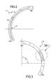
- FIG. 2 is a view of a low pressure side of seal ring segment according to an embodiment of the invention.
- FIG. 3 is a view of a high pressure side of a seal ring segment according to an embodiment of the invention.
- FIG. 4 is an end view of a transition portion
- FIG. 5 is a view of the bore region of a seal ring segment viewed looking from an inner diameter (ID) to an outer diameter (OD); and
- FIG. 6 is a top plan view of an assembly of seal ring segments according to an embodiment of the invention.
- Illustrated segment 10 includes a radial external surface 12, a radial internal surface 14 corresponding to a bore side of the segment, two or more transverse grooves 16, one or more lift augmentation formations (also referred to as "pads") 15, and a peripheral flow groove or peripheral channel 20 (see, e.g., FIG. 5 ).
- a portion of a plurality of sealing ring segments are combined to provide a seal against a rotating member, such as a shaft or runner.
- FIGS. 2 and 3 illustrate views of a low pressure side and a high pressure side, respectively, of a ring segment according to an embodiment of the invention.
- FIG. 5 depicts the bore region of a seal ring segment of the type shown in FIGS. 2 and 3 , including a plurality of pads 15 on the internal (or bore-side) surface 14 of segment 10.
- Each segment may cover a portion or angular segment of the 360° degrees, which may commonly be needed to provide a seal about a round or circular rotating member.
- ⁇ 1 is approximately 120°.
- the angular range covered by each segment will typically be a multiple of 360°, such as 72°, 90°, 120°, or 180°.
- the one or more pads 15 included on the bore-side may, for example, comprise one or more steps or pads, such as Rayleigh steps or pads.
- each pad 15 may, for instance, include a plateau 17, a sloped portion (also referred to as a "ramp” or “ramped portion”) 18, and an enlarged volume portion (also referred to as a "scooping groove") 19.
- the scooping groove 19 can start at or in proximity to an edge 22 of a transverse (e.g., feeding) groove 16 and can be configured to become progressively shallower in a direction moving along the surface of the pad away from the associated groove 16.
- the associated scooping groove 19 is configured to transition into a sloped portion or ramp 18.
- the sloped portion or ramp 18 may then further continue to become progressively more shallow (again taken in a direction moving away from the associated groove 16), but at a depth that is typically noticeably shallower than the scooping groove. At some further distance moving away from the associated groove 16 (e.g., at or about 26), the ramp 18 may transition into a plateau 17.
- the plateau 17 is generally the shallowest portion of the pad 15, and a plateau 17 is typically adjacent or in proximity to the next successive groove 16.
- the portions of the plateau 17 extend further radially outwardly than the remainder of the pad - i.e., the sloped portion 18 and the scooping groove 19.
- ramp 18 can be configured to transition into a plateau 17 (e.g., at 26) at a distance that is more than one-half the length of the pad 15 (viewed along its associated inner circumference).
- ramp 18 may be configured to transition into a plateau 17 (e.g., at 26) at a distance that is more than about 2/3 RDS of the distance along the pad 15 from the associated groove 16.
- the associated pressure may be used to offset assembly or system closing forces.
- air under the seal can be used to generate a pressure that may be used to at least partially offset contact pressure.
- the segment 10 may have an inner diameter of 3.000 inches at or about the position indicated as ID.
- the segment may further have a depth D 1 of the scooping groove 20 at or about the edge of transverse groove 16 that is about 0.012 inches, and that decreases to a depth of about 0.005 inches at a point where the scooping groove 19 transitions into the ramp portion 18.
- the depth may then further decrease, and become shallower, through the remainder of the ramp portion.
- the ramp portion may then further transition into a plateau 17.
- the segment may have a depth of about 0.001 at the intersection point identified as I.
- the depth associated with D 1 may be extended, at substantially the same or a similarly notable depth greater than ramp 18, for a length L 1 from groove 16 of about 0.020 inches.
- the radius at or about the positions designated R 1 and R 3 may be about 0.1250 inches, while the radius at or about the position designated R 2 may be about 1.580 inches.
- the ramp 18 is at least four times longer than its deepest radial dimension.
- an appropriately configured scooping groove 19 can help improve the ability of a pad 15 to generate and hold hydrodynamic pressure near the end of the member.
- the scooping groove at the entrance of the pad 15 can smooth the transition from a groove that, in conventional ring segments may have previously been very shallow near the leading edge of the member. For example, such a groove depth previously may have been around 0.001 inches, while the scooping groove 19 may have a depth that is about 0.030 inches.
- the present invention serves to reduce the effects of abrupt transition from the transverse groove 16 to the sloped portion or ramp 18.
- the configuration of the scooping groove (acting in part as a reservoir) can help prevent momentary starvation of fluid supply, which can lead to contact and wear. Consequently, the scooping groove 19 - having an increased depth (or scoop) proximate the transverse groove 16 - can serve to not only reduce entrance losses, but can provide a more continuous and smooth supply of fluid for the pad 15.
- a peripheral flow groove 20 is included on the internal (bore-side) surface 14.
- the transverse groove 16 and flow groove 20 can, for instance, be machined on the bore-side surface of each pad.
- Flow groove 20 can be provided at or in proximity to an end of the transverse groove 16 and can provide for fluid communication between one or more associated transverse grooves 16.
- the flow groove 20 can, among other things, help maintain a more uniform or stable pressure around portions of segment 10.
- flow groove 20 can be designed and configured to provide a desired equalization of pressure between pads 15.
- the ramp 18 and scooping groove 19 do not flow all the way through in an axial direction. Rather, the ramp 18 and scooping groove 19 may be bounded or guarded by sidewalls 30 on both the high-pressure and low-pressure sides, with the scooping groove introduced to serve as a reservoir to feed ramp 18. Heat generation and removal can be effectively addressed and improved by the present invention. That is, the segments and assembly can be configured to create sufficient opening force to lift the segment off the shaft and significantly reduce heat generation so that the useful life of the seal is extended.
- FIG. 2 illustrates a low pressure side view of a seal ring segment 10 according to an embodiment of the invention.
- the segment 10 may further include an axial pressure balance groove 32.
- each segment 10 may be one of a plurality of segments that together comprise a segmented seal ring or assembly.
- a general representation of an assembly 40 of seal ring segments 10 is shown in FIG. 6 .
- three seal ring segments, each covering a radial portion of approximately 120° each e.g., ⁇ 1 , ⁇ 2 , ⁇ 3
- the invention is not limited to assemblies comprised of three seal ring segments.
- the invention is not limited to an assembly in which each segment covers a substantially identical radial portion provided the assembly can adequately function in its intended environment.
- each seal ring segment 10 includes at least one transition portion, and preferably first and second transition portions 22a, 22b at each end.
- the transition portions serve to interface with or overlap (e.g., a sliding overlap) with an adjacent segment.
- the transition portion may comprise a joint or segment with a diagonal cut (see, e.g., FIG. 4 ) that mirrors the cut of the opposing end. That is, in an embodiment, a first transition portion 22a from one segment 10 can be configured to overlap and interface with as second transition portion 22b from an adjacent segment 10. Therefore, as desired for many applications, and potentially for manufacturing efficiencies, each of the segments can be identical to one another.
- each segment i.e., the surface opposing the bore-side surface shown in FIG. 5
- the retention groove may be configured such that, when the plurality of segments are positioned to engage one another, the spring is retained within the retention groove and holds the segments in an interconnected configuration.
- the retention groove and spring may be of the type commonly employed by conventional segmented sealing ring assemblies.
- an element such as a carbon pin, may be used to connect the assembly to a housing so that the assembly does not rotate relative to the housing.
Landscapes
- Engineering & Computer Science (AREA)
- General Engineering & Computer Science (AREA)
- Mechanical Engineering (AREA)
- Sealing Devices (AREA)
Abstract
Description
- The present invention relates to segmented radial seal assemblies.
- Segmented carbon radial or circumferential seals have been employed in a number of environments associated with compressible fluids, such as gases. They have been used, for example, in connection with gas turbine engines. Such radial seals typically act to, among other things, seal high pressure areas from low pressure areas. For some applications, Rayleigh steps or pads have been included to generate hydrodynamic opening force that enables a segmented seal to operate in a "non-contact" condition. The hydrodynamic opening force generated by a plurality of pads can distribute the associated force more evenly along a circumferential direction providing, among other things, a better balancing of forces. However, it has been found that an abrupt flow transition can occur with respect to the entrance of Rayleigh steps or pads and the transverse groove that helps to provide appropriate pressure balance. An abrupt transition between the transverse groove and the steps or pads can, among other things, cause associated flow losses and reduced efficiency.
- A segment of a seal assembly for sealing a higher pressure area from a lower pressure area is disclosed. The segment comprises a radial external surface, a radial internal surface for sealing against a rotating member, a transverse groove for maintaining a pressure around portions of the segment, and one or more pads including a scooping groove. The scooping groove is positioned at or in proximity to an edge of the transverse groove and provides for a transition flow between the one or more pads and the transverse groove.
- Embodiments of the invention will now be described, by way of example, with reference to the accompanying drawings, wherein:
-
FIG. 1 is a partial cut plane view of a seal ring segment according to an embodiment of the invention; -
FIG. 2 is a view of a low pressure side of seal ring segment according to an embodiment of the invention; -
FIG. 3 is a view of a high pressure side of a seal ring segment according to an embodiment of the invention; -
FIG. 4 is an end view of a transition portion; -
FIG. 5 is a view of the bore region of a seal ring segment viewed looking from an inner diameter (ID) to an outer diameter (OD); and -
FIG. 6 is a top plan view of an assembly of seal ring segments according to an embodiment of the invention. - Reference will now be made in detail to embodiments of the present invention, examples of which are described herein and illustrated in the accompanying drawings. While the invention will be described in conjunction with embodiments, it will be understood that they are not intended to limit the invention to these embodiments. On the contrary, the invention is intended to cover alternatives, modifications and equivalents, which may be included within the spirit and scope of the invention as defined by the appended claims.
- A partial cut plane view of a
seal ring segment 10 according to an embodiment of the invention is generally shown inFIG. 1 . Illustratedsegment 10 includes a radialexternal surface 12, a radialinternal surface 14 corresponding to a bore side of the segment, two or moretransverse grooves 16, one or more lift augmentation formations (also referred to as "pads") 15, and a peripheral flow groove or peripheral channel 20 (see, e.g.,FIG. 5 ). In an embodiment, a portion of a plurality of sealing ring segments are combined to provide a seal against a rotating member, such as a shaft or runner. -
FIGS. 2 and 3 illustrate views of a low pressure side and a high pressure side, respectively, of a ring segment according to an embodiment of the invention.FIG. 5 depicts the bore region of a seal ring segment of the type shown inFIGS. 2 and 3 , including a plurality ofpads 15 on the internal (or bore-side)surface 14 ofsegment 10. Each segment may cover a portion or angular segment of the 360° degrees, which may commonly be needed to provide a seal about a round or circular rotating member. In the embodiment illustrated inFIG. 3 , θ1 is approximately 120°. When a plurality of similar segments are involved, the angular range covered by each segment will typically be a multiple of 360°, such as 72°, 90°, 120°, or 180°. Moreover, as generally indicated inFIG. 3 (i.e., the portion not included with θ1), there may be a portion of each end of the segment that is intended to overlap or interconnect with an adjacent segment. Additionally, the one ormore pads 15 included on the bore-side may, for example, comprise one or more steps or pads, such as Rayleigh steps or pads. - As generally illustrated in connection with
FIG. 3A andFIG. 5 , eachpad 15 may, for instance, include aplateau 17, a sloped portion (also referred to as a "ramp" or "ramped portion") 18, and an enlarged volume portion (also referred to as a "scooping groove") 19. In an embodiment, thescooping groove 19 can start at or in proximity to anedge 22 of a transverse (e.g., feeding)groove 16 and can be configured to become progressively shallower in a direction moving along the surface of the pad away from the associatedgroove 16. At some distance from groove 16 (e.g., at or about 24), the associatedscooping groove 19 is configured to transition into a sloped portion orramp 18. The sloped portion orramp 18 may then further continue to become progressively more shallow (again taken in a direction moving away from the associated groove 16), but at a depth that is typically noticeably shallower than the scooping groove. At some further distance moving away from the associated groove 16 (e.g., at or about 26), theramp 18 may transition into aplateau 17. Theplateau 17 is generally the shallowest portion of thepad 15, and aplateau 17 is typically adjacent or in proximity to the nextsuccessive groove 16. In an embodiment, the portions of theplateau 17 extend further radially outwardly than the remainder of the pad - i.e., the slopedportion 18 and thescooping groove 19. - For example, without limitation,
ramp 18 can be configured to transition into a plateau 17 (e.g., at 26) at a distance that is more than one-half the length of the pad 15 (viewed along its associated inner circumference). In an embodiment,ramp 18 may be configured to transition into a plateau 17 (e.g., at 26) at a distance that is more than about 2/3RDS of the distance along thepad 15 from the associatedgroove 16. - The
pads 15, which are configured on the inner diameter, i.e., on the radialinternal surface 14, permit high pressure air to migrate down channels as a shaft rotates, the air or fluid may then be channeled into grooves by the pads. The associated pressure may be used to offset assembly or system closing forces. Essentially, air under the seal can be used to generate a pressure that may be used to at least partially offset contact pressure. - In some conventional assemblies, air that moves axially down a shaft is forced to make an abrupt 90° turn as it is forced under the segment. Such an abrupt turn can cause a loss of momentum in flow and, potentially, a drop-off in feed (i.e., a situation in which there is no air working). The inclusion of a scooping groove 19 (or "undercut" in the ramp 18), of the type generally illustrated, can serve as a reservoir to provides the airflow with more room to make the necessary turn, thereby improving the efficiency of the air that is pumped into
ramp 18 from thetransverse groove 16. Typically, one enlarged volume portion, or scoopinggroove 19, is provided per pad. - It is noted that many of the dimensions are dictated by the application and various manufacturers. Nevertheless, by way of further example, in an embodiment of the invention, such as that shown in
FIG. 1 , thesegment 10 may have an inner diameter of 3.000 inches at or about the position indicated as ID. The segment may further have a depth D1 of thescooping groove 20 at or about the edge oftransverse groove 16 that is about 0.012 inches, and that decreases to a depth of about 0.005 inches at a point where thescooping groove 19 transitions into theramp portion 18. The depth may then further decrease, and become shallower, through the remainder of the ramp portion. The ramp portion may then further transition into aplateau 17. By way of example, without limitation, the position indicated in connection with depth D2 inFIG. 1 may be about 0.005 inches, and the segment may have a depth of about 0.001 at the intersection point identified as I. In an embodiment, the depth associated with D1 may be extended, at substantially the same or a similarly notable depth greater thanramp 18, for a length L1 fromgroove 16 of about 0.020 inches. Further, the radius at or about the positions designated R1 and R3 may be about 0.1250 inches, while the radius at or about the position designated R2 may be about 1.580 inches. Moreover, in an embodiment, theramp 18 is at least four times longer than its deepest radial dimension. - Among other things, an appropriately configured scooping
groove 19 can help improve the ability of apad 15 to generate and hold hydrodynamic pressure near the end of the member. The scooping groove at the entrance of thepad 15 can smooth the transition from a groove that, in conventional ring segments may have previously been very shallow near the leading edge of the member. For example, such a groove depth previously may have been around 0.001 inches, while thescooping groove 19 may have a depth that is about 0.030 inches. The present invention, among other things, serves to reduce the effects of abrupt transition from thetransverse groove 16 to the sloped portion orramp 18. - Moreover, since the associated rotating shaft is not perfectly round, and the seal tracks the shaft, the configuration of the scooping groove (acting in part as a reservoir) can help prevent momentary starvation of fluid supply, which can lead to contact and wear. Consequently, the scooping groove 19 - having an increased depth (or scoop) proximate the transverse groove 16 - can serve to not only reduce entrance losses, but can provide a more continuous and smooth supply of fluid for the
pad 15. - Turning again to
FIG. 5 , in an embodiment, aperipheral flow groove 20 is included on the internal (bore-side)surface 14. Thetransverse groove 16 and flowgroove 20 can, for instance, be machined on the bore-side surface of each pad.Flow groove 20 can be provided at or in proximity to an end of thetransverse groove 16 and can provide for fluid communication between one or more associatedtransverse grooves 16. Theflow groove 20 can, among other things, help maintain a more uniform or stable pressure around portions ofsegment 10. Moreover, flowgroove 20 can be designed and configured to provide a desired equalization of pressure betweenpads 15. - In an embodiment of the invention, the
ramp 18 and scoopinggroove 19 do not flow all the way through in an axial direction. Rather, theramp 18 and scoopinggroove 19 may be bounded or guarded by sidewalls 30 on both the high-pressure and low-pressure sides, with the scooping groove introduced to serve as a reservoir to feedramp 18. Heat generation and removal can be effectively addressed and improved by the present invention. That is, the segments and assembly can be configured to create sufficient opening force to lift the segment off the shaft and significantly reduce heat generation so that the useful life of the seal is extended. -
FIG. 2 illustrates a low pressure side view of aseal ring segment 10 according to an embodiment of the invention. As generally shown, thesegment 10 may further include an axialpressure balance groove 32. - In an embodiment of the invention, each
segment 10 may be one of a plurality of segments that together comprise a segmented seal ring or assembly. A general representation of anassembly 40 ofseal ring segments 10 is shown inFIG. 6 . In an embodiment, three seal ring segments, each covering a radial portion of approximately 120° each (e.g., θ1, θ2, θ3) are interconnected or otherwise assembled to cover a full 360° associated with the radial internal surface of the assembly. However, as understood by those of skill in the field, the invention is not limited to assemblies comprised of three seal ring segments. Further, while it may be preferable for a number of applications, the invention is not limited to an assembly in which each segment covers a substantially identical radial portion provided the assembly can adequately function in its intended environment. - As generally illustrated in
FIGS. 2 and 3 , eachseal ring segment 10 includes at least one transition portion, and preferably first andsecond transition portions FIG. 4 ) that mirrors the cut of the opposing end. That is, in an embodiment, afirst transition portion 22a from onesegment 10 can be configured to overlap and interface with assecond transition portion 22b from anadjacent segment 10. Therefore, as desired for many applications, and potentially for manufacturing efficiencies, each of the segments can be identical to one another. - In an embodiment, the radial external surface of each segment, i.e., the surface opposing the bore-side surface shown in
FIG. 5 , may include a retention groove (also referred to as a channel) for receiving a spring. The retention groove may be configured such that, when the plurality of segments are positioned to engage one another, the spring is retained within the retention groove and holds the segments in an interconnected configuration. If desired, the retention groove and spring may be of the type commonly employed by conventional segmented sealing ring assemblies. - Additionally, for some embodiments, an element, such as a carbon pin, may be used to connect the assembly to a housing so that the assembly does not rotate relative to the housing.
- The foregoing descriptions of specific embodiments of the present invention have been presented for purposes of illustration and description. They are not intended to be exhaustive or to limit the invention to the precise forms disclosed, and various modifications and variations are possible in light of the above teaching. The embodiments were chosen and described in order to explain the principles of the invention and its practical application, to thereby enable others skilled in the art to utilize the invention and various embodiments with various modifications as are suited to the particular use contemplated. It is intended that the scope of the invention be defined by the claims appended hereto and their equivalents.
Claims (23)
- A segment (10) of a seal assembly for sealing against a rotating member, the segment (10) comprising:a radial external surface (12);a radial internal surface (14) for sealing against said rotating member;a transverse groove (16) for maintaining a pressure around portions of the segment (10); andone or more pads (15), including a scooping groove (19) at or in proximity to the transverse groove (16), the scooping groove (19) providing a transition flow between the one or more pads (15) and the transverse groove (16).
- The segment (10) of claim 1, wherein the pad (15) comprises a Rayleigh step or pad.
- The segment (10) of claim 1, wherein the transverse groove (16) is semicircular.
- The segment (10) of claim 1, wherein the scooping groove (19) transitions directly into the transverse groove (16).
- The segment (10) of claim 1, wherein the pad (15) includes a ramped portion (18).
- The segment (10)of claim 1, wherein the pad (15) includes a ramped portion (18) and a plateau (17).
- The segment (10) of claim 6, wherein the plateau (17) is adjacent or in proximity to another transverse groove (16).
- The segment (10) of claim 6, wherein the plateau (17) extends further radially outwardly than the ramped portion (18) and the scooping groove (19).
- The segment (10) of claim 5, wherein the ramped portion (18) transitions into the scooping groove (19) with an increasing depth moving in a direction toward the transverse groove (16).
- The segment (10) of claim 1, wherein the segment (10) includes a joint or connection configuration at each radial end that is configured for connection to another segment.
- The segment of claim 10, wherein the segment includes a joint or connection configuration (22a) that is adapted for an interconnecting or interlocking with a joint or connection (22b) of an adjacent segment (10).
- The segment (10) of claim 1, wherein the radial external surface (12) includes at least one retention groove for retaining a portion of a spring.
- The segment (10) of claim 12, wherein the at least one retention groove is discontinuous.
- The segment (10) of claim 1, including an element for connection to a housing, the element including an anti-rotation feature.
- The segment (10) of claim 1, wherein the volume associated with the scooping groove (19) is configured to provide room for the efficient flow of an associated fluid between the transverse groove (16) and a sloped or ramped portion (18) of the pad (15).
- The segment (10) of claim 1, wherein the scooping groove (19) is at least four times longer than its deepest radial dimension.
- The segment (10) of claim 1, wherein the scooping groove (19) includes a side wall (30) on both a high-pressure and low-pressure side of the scooping groove (19).
- The segment (10) of claim 1, wherein the scooping groove (19) and a ramp portion (18) form a rotational scoop.
- The segment (10)of claim 1, wherein the segment (10) is comprised of carbon, plastic, ceramic, or metal.
- A segment (10) of a seal assembly for sealing against a rotating member, the segment comprising:a radial external surface (12);a radial internal surface (14) for sealing against said rotating member;a transverse groove (16) for maintaining a pressure around portions of the segment (10); anda plurality of pads (15) including a plateau (17), a ramped portion (18) adjacent the plateau (17), and a scooping groove (19) adjacent the ramped portion (18) and at or in proximity to the transverse groove (16);wherein the ramped portion (18) transitions into the scooping groove (19) with an increasing depth moving in a direction toward the transverse groove (16), the scooping groove (19) has a depth greater than the greatest depth of the ramped portion (18), and the scooping groove (19) provides a transition flow between the transverse groove (16) and the ramped portion (18).
- A segmented seal assembly (40) for sealing against a rotating member, the assembly comprising:a plurality of segments (10) including a radial outer surface (12), a radial inner surface (14) for sealing against said rotating member, a transverse groove (16) for maintaining a pressure around portions of the segment (10), and one or more pads (15) that create lift augmentation pressure, the one or more pads (15) including a scooping groove (19) at or in proximity to an edge (22) of the transverse groove (16);wherein the scooping groove (19) provides for a transition flow between the one or more pads (15) and the transverse groove (16).
- The assembly (40) of claim 21, wherein the assembly includes a means for retaining the plurality of segments (10).
- The assembly (40) of claim 22, wherein the means comprises a spring.
Applications Claiming Priority (1)
| Application Number | Priority Date | Filing Date | Title |
|---|---|---|---|
| US11/743,005 US7770895B2 (en) | 2007-05-01 | 2007-05-01 | Segmented seal portion and assembly |
Publications (2)
| Publication Number | Publication Date |
|---|---|
| EP1988313A1 true EP1988313A1 (en) | 2008-11-05 |
| EP1988313B1 EP1988313B1 (en) | 2013-09-04 |
Family
ID=39717630
Family Applications (1)
| Application Number | Title | Priority Date | Filing Date |
|---|---|---|---|
| EP08008172.2A Active EP1988313B1 (en) | 2007-05-01 | 2008-04-29 | Segmented seal portion and assembly |
Country Status (2)
| Country | Link |
|---|---|
| US (1) | US7770895B2 (en) |
| EP (1) | EP1988313B1 (en) |
Cited By (3)
| Publication number | Priority date | Publication date | Assignee | Title |
|---|---|---|---|---|
| EP2886915A1 (en) * | 2013-12-18 | 2015-06-24 | Kaydon Ring & Seal, Inc. | Bidirectional lift-off circumferential shaft seal segment and a shaft seal including a plurality of the segments |
| EP2855888A4 (en) * | 2012-05-31 | 2016-01-20 | United Technologies Corp | SEGMENTED SEAL WITH SEVERE ENDS |
| FR3030008A1 (en) * | 2014-12-15 | 2016-06-17 | Kaydon Ring & Seal Inc |
Families Citing this family (37)
| Publication number | Priority date | Publication date | Assignee | Title |
|---|---|---|---|---|
| US8657299B2 (en) | 2004-07-15 | 2014-02-25 | John E. Rode | Mounting rings for shafts |
| US20080284105A1 (en) * | 2006-06-21 | 2008-11-20 | Thurai Manik Vasagar | Low and reverse pressure application hydrodynamic pressurizing seals |
| US7914007B2 (en) * | 2008-12-30 | 2011-03-29 | Eaton Corporation | Segmented seal with hydrodynamic feature and assembly |
| WO2011025484A1 (en) * | 2009-08-27 | 2011-03-03 | Stein Seal Company | Hydrodynamic circumferential seal system for large translations |
| US8905407B2 (en) | 2011-03-02 | 2014-12-09 | Eaton Corporation | Segmented seal with axial load control feature |
| AU2014206300B2 (en) | 2013-01-16 | 2016-10-13 | Eagle Industry Co., Ltd. | Sliding part |
| US9261139B2 (en) | 2013-02-06 | 2016-02-16 | Trelleborg Sealing Solutions Us | Friction-reducing geometric surface feature |
| US9790863B2 (en) | 2013-04-05 | 2017-10-17 | Honeywell International Inc. | Fluid transfer seal assemblies, fluid transfer systems, and methods for transferring process fluid between stationary and rotating components using the same |
| WO2015031474A1 (en) | 2013-08-27 | 2015-03-05 | Eaton Corporation | Seal ring composite for improved hydrodynamic seal performance |
| JP6340233B2 (en) * | 2014-04-08 | 2018-06-06 | Kyb株式会社 | Cylinder device |
| US9714712B2 (en) | 2014-08-15 | 2017-07-25 | Eaton Corporation | Hydrodynamic mating ring with integrated groove inlet pressure control |
| US9927033B2 (en) | 2015-06-29 | 2018-03-27 | Kaydon Ring & Seal, Inc. | Split circumferential lift-off seal segment |
| US10393272B2 (en) | 2015-11-24 | 2019-08-27 | Kaydon Ring & Seal, Inc. | Sleeve configured for use in a non-contacting gas seal and gas seal including the sleeve |
| US10670151B2 (en) * | 2015-12-16 | 2020-06-02 | Eaton Intelligent Power Limited | Segmented seal with shallow groove |
| US11125334B2 (en) | 2016-12-21 | 2021-09-21 | Eaton Intelligent Power Limited | Hydrodynamic sealing component and assembly |
| DE112018003513T8 (en) * | 2017-07-10 | 2020-05-28 | Siemens Energy, Inc. | Generator seal arrangement |
| US10989058B2 (en) | 2018-04-19 | 2021-04-27 | General Electric Company | Segmented piston seal system |
| WO2020027102A1 (en) | 2018-08-01 | 2020-02-06 | イーグル工業株式会社 | Slide component |
| CN112424514B (en) | 2018-08-24 | 2023-04-28 | 伊格尔工业股份有限公司 | Sliding member |
| US11199103B2 (en) | 2018-09-06 | 2021-12-14 | General Electric Company | Seal assembly for a turbomachine |
| CN116025714B (en) | 2018-10-01 | 2026-03-27 | 伊格尔工业股份有限公司 | sliding parts |
| CN112789434B (en) | 2018-10-24 | 2023-09-29 | 伊格尔工业股份有限公司 | sliding parts |
| EP3889474A4 (en) | 2018-11-30 | 2022-08-10 | Eagle Industry Co., Ltd. | Sliding component |
| KR102541901B1 (en) | 2018-12-21 | 2023-06-13 | 이구루코교 가부시기가이샤 | sliding parts |
| CN113260797B (en) | 2019-02-04 | 2023-02-14 | 伊格尔工业股份有限公司 | sliding parts |
| US11933405B2 (en) | 2019-02-14 | 2024-03-19 | Eagle Industry Co., Ltd. | Sliding component |
| EP4317728B1 (en) | 2019-02-21 | 2026-01-14 | Eagle Industry Co., Ltd. | Sliding components |
| KR102616659B1 (en) | 2019-04-24 | 2023-12-21 | 이구루코교 가부시기가이샤 | sliding parts |
| JP7399966B2 (en) | 2019-07-26 | 2023-12-18 | イーグル工業株式会社 | sliding parts |
| US11391377B2 (en) | 2019-11-15 | 2022-07-19 | Eaton Intelligent Power Limited | Hydraulic seal |
| JP7705708B2 (en) | 2019-12-19 | 2025-07-10 | イートン インテリジェント パワー リミテッド | Self-correcting hydrodynamic seals |
| US12276338B2 (en) | 2020-06-02 | 2025-04-15 | Eagle Industry Co., Ltd. | Sliding component |
| KR20250116162A (en) | 2020-06-02 | 2025-07-31 | 이구루코교 가부시기가이샤 | Sliding component |
| JP7608033B2 (en) | 2021-03-12 | 2025-01-06 | イーグル工業株式会社 | Sliding parts |
| EP4372253A4 (en) * | 2021-07-13 | 2025-07-16 | Eagle Ind Co Ltd | SLIDING COMPONENTS |
| EP4411182A4 (en) | 2021-09-28 | 2025-09-17 | Eagle Ind Co Ltd | Sliding component |
| US11713688B2 (en) | 2021-12-03 | 2023-08-01 | Raytheon Technologies Corporation | Pressure-balanced carbon seal |
Citations (4)
| Publication number | Priority date | Publication date | Assignee | Title |
|---|---|---|---|---|
| US4082296A (en) * | 1976-05-26 | 1978-04-04 | Stein Philip C | Seal for sealing between a rotating member and a housing |
| US5169159A (en) * | 1991-09-30 | 1992-12-08 | General Electric Company | Effective sealing device for engine flowpath |
| EP0523899A1 (en) * | 1991-07-15 | 1993-01-20 | General Electric Company | Fluid bearing face seal for gas turbine engines |
| EP1302709A2 (en) * | 2001-10-15 | 2003-04-16 | Stein Seal Company | High-pressure-film-riding seals for rotating shafts |
Family Cites Families (13)
| Publication number | Priority date | Publication date | Assignee | Title |
|---|---|---|---|---|
| US3124502A (en) * | 1964-03-10 | Composite fibrous lubricant packing | ||
| US3575424A (en) * | 1969-11-28 | 1971-04-20 | Koppers Co Inc | Pressure balanced circumferential seal assembly |
| US3743303A (en) * | 1970-12-29 | 1973-07-03 | Gen Electric | Force balanced split ring dynamic shaft seals |
| US4145058A (en) * | 1977-07-08 | 1979-03-20 | The United States Of America As Represented By The Administrator Of The National Aeronautics And Space Administration | Shaft seal assembly for high speed and high pressure applications |
| US4199152A (en) * | 1979-03-19 | 1980-04-22 | Rockwell International Corporation | Hydrostatic seal for centrifugal pumps |
| US4685684A (en) * | 1986-02-14 | 1987-08-11 | Ballard Michael J | Dynamic seal |
| US5058904A (en) | 1990-02-21 | 1991-10-22 | Eg&G Sealol Inc. | Self-contained sealing ring assembly |
| US5370402A (en) | 1993-05-07 | 1994-12-06 | Eg&G Sealol, Inc. | Pressure balanced compliant seal device |
| US5632493A (en) | 1995-05-04 | 1997-05-27 | Eg&G Sealol, Inc. | Compliant pressure balanced seal apparatus |
| FR2782122B1 (en) | 1998-08-05 | 2000-09-15 | Snecma | SEALING ARRANGEMENT WITH AUTOMATIC GAME ADJUSTMENT |
| US6145843A (en) | 1998-10-19 | 2000-11-14 | Stein Seal Company | Hydrodynamic lift seal for use with compressible fluids |
| US6328528B1 (en) * | 2000-04-25 | 2001-12-11 | Freudenberg-Nok General Partnership | Elastomeric pump impeller |
| US7540501B2 (en) * | 2004-11-05 | 2009-06-02 | Flowserve Management Company | Segmented shaft seal |
-
2007
- 2007-05-01 US US11/743,005 patent/US7770895B2/en active Active
-
2008
- 2008-04-29 EP EP08008172.2A patent/EP1988313B1/en active Active
Patent Citations (4)
| Publication number | Priority date | Publication date | Assignee | Title |
|---|---|---|---|---|
| US4082296A (en) * | 1976-05-26 | 1978-04-04 | Stein Philip C | Seal for sealing between a rotating member and a housing |
| EP0523899A1 (en) * | 1991-07-15 | 1993-01-20 | General Electric Company | Fluid bearing face seal for gas turbine engines |
| US5169159A (en) * | 1991-09-30 | 1992-12-08 | General Electric Company | Effective sealing device for engine flowpath |
| EP1302709A2 (en) * | 2001-10-15 | 2003-04-16 | Stein Seal Company | High-pressure-film-riding seals for rotating shafts |
Cited By (4)
| Publication number | Priority date | Publication date | Assignee | Title |
|---|---|---|---|---|
| EP2855888A4 (en) * | 2012-05-31 | 2016-01-20 | United Technologies Corp | SEGMENTED SEAL WITH SEVERE ENDS |
| EP2886915A1 (en) * | 2013-12-18 | 2015-06-24 | Kaydon Ring & Seal, Inc. | Bidirectional lift-off circumferential shaft seal segment and a shaft seal including a plurality of the segments |
| US9695940B2 (en) | 2013-12-18 | 2017-07-04 | Kaydon Ring & Seal, Inc. | Bidirectional lift-off circumferential shaft seal segment and a shaft seal including a plurality of the segments |
| FR3030008A1 (en) * | 2014-12-15 | 2016-06-17 | Kaydon Ring & Seal Inc |
Also Published As
| Publication number | Publication date |
|---|---|
| EP1988313B1 (en) | 2013-09-04 |
| US7770895B2 (en) | 2010-08-10 |
| US20080272552A1 (en) | 2008-11-06 |
Similar Documents
| Publication | Publication Date | Title |
|---|---|---|
| US7770895B2 (en) | Segmented seal portion and assembly | |
| EP2376822B1 (en) | Segmented seal with hydrodynamic feature and assembly | |
| US7735833B2 (en) | Double padded finger seal | |
| CN103429938B (en) | Segmented seals with axial load control properties | |
| EP2977654B1 (en) | Sliding component | |
| KR102276083B1 (en) | sliding parts | |
| EP3309431B1 (en) | Slide component | |
| CN105736701B (en) | Arch combination lip ring and ring sealing system with the lip ring | |
| US7726660B2 (en) | Non-contacting seal for rotating surfaces | |
| US9695940B2 (en) | Bidirectional lift-off circumferential shaft seal segment and a shaft seal including a plurality of the segments | |
| US20180128378A1 (en) | Sliding component | |
| US10337619B2 (en) | Seal ring composite for improved hydrodynamic seal performance | |
| US9841105B2 (en) | Sealing lip and seal | |
| CN108468573B (en) | Axial flow turbocharger double floating ring thrust bearing structure | |
| US7625122B2 (en) | Fluid dynamic bearing | |
| KR20230164724A (en) | sliding parts | |
| US11391377B2 (en) | Hydraulic seal | |
| CN102782376A (en) | Sealing device | |
| CN113494609A (en) | Sealing ring | |
| EP4102113B1 (en) | Sliding component | |
| CN112412795A (en) | Labyrinth seal structure and screw compressor |
Legal Events
| Date | Code | Title | Description |
|---|---|---|---|
| PUAI | Public reference made under article 153(3) epc to a published international application that has entered the european phase |
Free format text: ORIGINAL CODE: 0009012 |
|
| AK | Designated contracting states |
Kind code of ref document: A1 Designated state(s): AT BE BG CH CY CZ DE DK EE ES FI FR GB GR HR HU IE IS IT LI LT LU LV MC MT NL NO PL PT RO SE SI SK TR |
|
| AX | Request for extension of the european patent |
Extension state: AL BA MK RS |
|
| 17P | Request for examination filed |
Effective date: 20090324 |
|
| 17Q | First examination report despatched |
Effective date: 20090427 |
|
| AKX | Designation fees paid |
Designated state(s): DE FR GB SE |
|
| GRAP | Despatch of communication of intention to grant a patent |
Free format text: ORIGINAL CODE: EPIDOSNIGR1 |
|
| GRAS | Grant fee paid |
Free format text: ORIGINAL CODE: EPIDOSNIGR3 |
|
| GRAA | (expected) grant |
Free format text: ORIGINAL CODE: 0009210 |
|
| AK | Designated contracting states |
Kind code of ref document: B1 Designated state(s): DE FR GB SE |
|
| REG | Reference to a national code |
Ref country code: GB Ref legal event code: FG4D |
|
| REG | Reference to a national code |
Ref country code: DE Ref legal event code: R096 Ref document number: 602008027239 Country of ref document: DE Effective date: 20131031 |
|
| PG25 | Lapsed in a contracting state [announced via postgrant information from national office to epo] |
Ref country code: SE Free format text: LAPSE BECAUSE OF FAILURE TO SUBMIT A TRANSLATION OF THE DESCRIPTION OR TO PAY THE FEE WITHIN THE PRESCRIBED TIME-LIMIT Effective date: 20130904 |
|
| REG | Reference to a national code |
Ref country code: DE Ref legal event code: R097 Ref document number: 602008027239 Country of ref document: DE |
|
| PLBE | No opposition filed within time limit |
Free format text: ORIGINAL CODE: 0009261 |
|
| STAA | Information on the status of an ep patent application or granted ep patent |
Free format text: STATUS: NO OPPOSITION FILED WITHIN TIME LIMIT |
|
| 26N | No opposition filed |
Effective date: 20140605 |
|
| REG | Reference to a national code |
Ref country code: DE Ref legal event code: R097 Ref document number: 602008027239 Country of ref document: DE Effective date: 20140605 |
|
| REG | Reference to a national code |
Ref country code: FR Ref legal event code: PLFP Year of fee payment: 9 |
|
| REG | Reference to a national code |
Ref country code: FR Ref legal event code: PLFP Year of fee payment: 10 |
|
| REG | Reference to a national code |
Ref country code: FR Ref legal event code: PLFP Year of fee payment: 11 |
|
| REG | Reference to a national code |
Ref country code: GB Ref legal event code: 732E Free format text: REGISTERED BETWEEN 20181115 AND 20181130 |
|
| REG | Reference to a national code |
Ref country code: DE Ref legal event code: R082 Ref document number: 602008027239 Country of ref document: DE Ref country code: DE Ref legal event code: R081 Ref document number: 602008027239 Country of ref document: DE Owner name: EATON INTELLIGENT POWER LIMITED, IE Free format text: FORMER OWNER: EATON CORPORATION, CLEVELAND, OHIO, US |
|
| P01 | Opt-out of the competence of the unified patent court (upc) registered |
Effective date: 20230521 |
|
| PGFP | Annual fee paid to national office [announced via postgrant information from national office to epo] |
Ref country code: DE Payment date: 20250319 Year of fee payment: 18 |
|
| PGFP | Annual fee paid to national office [announced via postgrant information from national office to epo] |
Ref country code: GB Payment date: 20260319 Year of fee payment: 19 |
|
| PGFP | Annual fee paid to national office [announced via postgrant information from national office to epo] |
Ref country code: FR Payment date: 20260319 Year of fee payment: 19 |