EP1988298A2 - Linear travel, self aligning, rotating, retention clamp - Google Patents
Linear travel, self aligning, rotating, retention clamp Download PDFInfo
- Publication number
- EP1988298A2 EP1988298A2 EP08008297A EP08008297A EP1988298A2 EP 1988298 A2 EP1988298 A2 EP 1988298A2 EP 08008297 A EP08008297 A EP 08008297A EP 08008297 A EP08008297 A EP 08008297A EP 1988298 A2 EP1988298 A2 EP 1988298A2
- Authority
- EP
- European Patent Office
- Prior art keywords
- shaft
- clamping member
- clamping
- threaded portion
- stop
- Prior art date
- Legal status (The legal status is an assumption and is not a legal conclusion. Google has not performed a legal analysis and makes no representation as to the accuracy of the status listed.)
- Granted
Links
Images



Classifications
-
- F—MECHANICAL ENGINEERING; LIGHTING; HEATING; WEAPONS; BLASTING
- F16—ENGINEERING ELEMENTS AND UNITS; GENERAL MEASURES FOR PRODUCING AND MAINTAINING EFFECTIVE FUNCTIONING OF MACHINES OR INSTALLATIONS; THERMAL INSULATION IN GENERAL
- F16B—DEVICES FOR FASTENING OR SECURING CONSTRUCTIONAL ELEMENTS OR MACHINE PARTS TOGETHER, e.g. NAILS, BOLTS, CIRCLIPS, CLAMPS, CLIPS OR WEDGES; JOINTS OR JOINTING
- F16B2/00—Friction-grip releasable fastenings
- F16B2/02—Clamps, i.e. with gripping action effected by positive means other than the inherent resistance to deformation of the material of the fastening
- F16B2/06—Clamps, i.e. with gripping action effected by positive means other than the inherent resistance to deformation of the material of the fastening external, i.e. with contracting action
- F16B2/12—Clamps, i.e. with gripping action effected by positive means other than the inherent resistance to deformation of the material of the fastening external, i.e. with contracting action using sliding jaws
-
- Y—GENERAL TAGGING OF NEW TECHNOLOGICAL DEVELOPMENTS; GENERAL TAGGING OF CROSS-SECTIONAL TECHNOLOGIES SPANNING OVER SEVERAL SECTIONS OF THE IPC; TECHNICAL SUBJECTS COVERED BY FORMER USPC CROSS-REFERENCE ART COLLECTIONS [XRACs] AND DIGESTS
- Y10—TECHNICAL SUBJECTS COVERED BY FORMER USPC
- Y10T—TECHNICAL SUBJECTS COVERED BY FORMER US CLASSIFICATION
- Y10T403/00—Joints and connections
- Y10T403/59—Manually releaseable latch type
-
- Y—GENERAL TAGGING OF NEW TECHNOLOGICAL DEVELOPMENTS; GENERAL TAGGING OF CROSS-SECTIONAL TECHNOLOGIES SPANNING OVER SEVERAL SECTIONS OF THE IPC; TECHNICAL SUBJECTS COVERED BY FORMER USPC CROSS-REFERENCE ART COLLECTIONS [XRACs] AND DIGESTS
- Y10—TECHNICAL SUBJECTS COVERED BY FORMER USPC
- Y10T—TECHNICAL SUBJECTS COVERED BY FORMER US CLASSIFICATION
- Y10T403/00—Joints and connections
- Y10T403/59—Manually releaseable latch type
- Y10T403/591—Manually releaseable latch type having operating mechanism
-
- Y—GENERAL TAGGING OF NEW TECHNOLOGICAL DEVELOPMENTS; GENERAL TAGGING OF CROSS-SECTIONAL TECHNOLOGIES SPANNING OVER SEVERAL SECTIONS OF THE IPC; TECHNICAL SUBJECTS COVERED BY FORMER USPC CROSS-REFERENCE ART COLLECTIONS [XRACs] AND DIGESTS
- Y10—TECHNICAL SUBJECTS COVERED BY FORMER USPC
- Y10T—TECHNICAL SUBJECTS COVERED BY FORMER US CLASSIFICATION
- Y10T403/00—Joints and connections
- Y10T403/59—Manually releaseable latch type
- Y10T403/597—Swiveled bolt
-
- Y—GENERAL TAGGING OF NEW TECHNOLOGICAL DEVELOPMENTS; GENERAL TAGGING OF CROSS-SECTIONAL TECHNOLOGIES SPANNING OVER SEVERAL SECTIONS OF THE IPC; TECHNICAL SUBJECTS COVERED BY FORMER USPC CROSS-REFERENCE ART COLLECTIONS [XRACs] AND DIGESTS
- Y10—TECHNICAL SUBJECTS COVERED BY FORMER USPC
- Y10T—TECHNICAL SUBJECTS COVERED BY FORMER US CLASSIFICATION
- Y10T403/00—Joints and connections
- Y10T403/59—Manually releaseable latch type
- Y10T403/599—Spring biased manipulator
Definitions
- Clamping devices which are used to join a first component to a second component.
- a threaded rod having a threaded clamping member is rotated to drive the clamping member into engagement with a component to seat the component in an enclosure such as a cabinet, portable pack, or the like.
- a retention clamp includes a shaft having a stop member and a first threaded portion, the first threaded portion including a left hand thread.
- a clamping member is threadably connected to the first threaded portion.
- a biasing member positioned between the stop member and the clamping member is operable to transfer a rotational force applied to the shaft to the clamping member to rotate the clamping member into an engagement position.
- a retention clamp includes a shaft having a stop member and a first threaded portion, the first threaded portion including a left hand thread.
- a clamping member is threadably connected to the first threaded portion.
- An indexing member is slidably received over the first threaded portion and positioned between the stop member and the clamping member. The indexing member is frictionally engageable with the clamping member such that rotation of the indexing member rotates the clamping member.
- a biasing member positioned between the stop member and the indexing member is operable to transfer a rotational force applied to the shaft from the stop member to the indexing member to rotate the clamping member into an engagement position.
- a retention clamp system includes an assembly having a shaft having a stop member and a first threaded portion, the first threaded portion including a left hand thread.
- a clamping member is threadably connected to the first threaded portion, the clamping member having an engagement surface angled with respect to a longitudinal axis of the shaft.
- a biasing member positioned between the stop member and the clamping member transfers a rotational force applied to the shaft to the clamping member to rotate the clamping member into an engagement position.
- An enclosure member fixedly receives the assembly.
- a device is received in the enclosure, the device having an engagement post adapted to engage the engagement surface of the clamping member when the shaft is rotated.
- a clamp assembly 10 includes a screw member 11 having a flap member 12 rotatably connected thereto.
- screw member 11 can include a drive member portion 14 provided from one of a plurality of geometric shapes which as shown in this view can include a polygonal shape having multiple sides such as the six-sided shape shown in Figure 1 .
- Screw member 11 can further include a shaft portion 16 connected to drive member portion 14 having a substantially circular or tubular shape, which directly transitions into a stop member 18.
- biasing member 22 can include an extending rod or first leg 24 which is received in a first leg receiving slot 25 of stop member 18, and an opposed extending rod or second leg 26 received in a second leg receiving slot 27 created in indexing member 20.
- First leg 24 and second leg 26 of biasing member 22 provide positive rotational engagement so that a rotational force applied to screw member 11 is translated from stop member 18 by first leg 24 through biasing member 22 and through second leg 26 to indexing member 20, while biasing member 22 can extend or compress with displacement of indexing member 20.
- Biasing member 22 is freely disposed over a threaded portion 28 of screw member 11.
- Indexing member 20 is similarly freely and slidably disposed over threaded portion 28 so that indexing member 20 is free to longitudinally slide with respect to fixed stop member 18.
- Threaded portion 28 is provided with a plurality of left hand threads 29.
- a clamping member defining a clamping hook 30 having mating internal left hand threads is threadably engaged with left hand threads 29 of threaded portion 28 and abuts indexing member 20.
- Flap member 12 is rotatably connected to screw member 11 using a retention pin 41.
- a plurality of first ratchet teeth 42 are provided at a clamping hook facing end of indexing member 20.
- First ratchet teeth 42 engage individual ones of a plurality of second ratchet teeth 43 provided on clamping hook 30.
- First ratchet teeth 42 can ratchet against second ratchet teeth 43 in response to rotation of screw member 11 which by engagement with first leg 24 and second leg 26 of biasing member 22 rotate indexing member 20 and thereby rotate clamping hook 30.
- Clamping hook 30 further provides a cavity 44 defining an engagement face 46.
- Vhicular adapter assembly 48 can include a communication device 50 such as a portable radio which is received within an enclosure member such as an enclosure such as a cabinet 52 and clamped using clamp assembly 10.
- a communication device 50 such as a portable radio which is received within an enclosure member such as an enclosure such as a cabinet 52 and clamped using clamp assembly 10.
- clamp assembly 10 is positioned as shown having first and second washers 36, 38 located on opposite sides of an engagement member such as a retention wall 54 of cabinet 52.
- Self locking nut 40 is then threadably engaged with threaded end 34 to longitudinally fix clamp assembly 10 into the position shown, while permitting rotation of screw member 11 by flap member 12.
- stop member 18 By rotating screw member 11 using flap member 12 in a clockwise engagement rotation direction "A", stop member 18 imparts a rotation force to clamping hook 30 through biasing member 22 to rotate clamping hook 30 into the position shown. Engagement face 46 of clamping hook 30 engages with an engagement member such as an engagement wall 56 of communication device 50. Further rotation of screw member 11 in the engagement rotation direction “A” translates clamping hook 30 using left hand threads 29 in a hook engagement direction "B" to seat against engagement wall 56.
- first ratchet teeth 42 of indexing member 20 rotating in response to rotational torque applied to biasing member 22 ratchet with and therefore engage opposing second ratchet teeth 43 of clamping hook 30 to position clamping hook 30 as shown in an aperture 57 of cabinet 52 for subsequent engagement of clamping hook 30 with engagement wall 56.
- flap member 12 is rotated to the position shown to maximize torque when rotating screw member 11. Flap member 12 can then be rotated (similar to the configuration shown in phantom in Figure 6 ) until it contacts drive member portion 14 of screw member 11 which repositions flap member 12 to provide additional access area for communication device 50.
- clamping hook 30 is shown positioned to allow engagement face 46 to contact an engagement face 58 defined within a body cavity 60 of engagement wall 56.
- Clamping hook 30 is also positioned within a clamp cavity 62 defined by both communication device 50 and cabinet 52. Clamping hook 30 is therefore free to rotate within clamp cavity 62 and must be rotated into the body cavity 60 as shown in order to permit engagement between engagement face 46 of clamping hook 30 and engagement face 58 of engagement wall 56.
- self locking nut 40 abuts a shoulder 63 of second shaft portion 32 allowing self locking nut 40 and screw member 11 to co-rotate, with self locking nut 40 able to rotate with respect to second washer 38 which is substantially fixed against rotation by contact with retention wall 54.
- Second washer 38 therefore acts as a rotational bearing surface for self locking nut 40.
- first washer 36 is non-rotatably fixed with respect to retention wall 54.
- Second shaft portion 32 is diametrically sized to provide a rotational clearance fit from an inner wall of an aperture provided in retention wall 54.
- a screw member 64 is modified from screw member 11.
- Screw member 64 includes a cylindrical portion 66 which replaces both drive member portion 14 and shaft portion 16 of screw member 11.
- Cylindrical portion 66 has a cylinder diameter "C” and a cylinder length "D” which can vary to suit the arrangement of vehicular adapter assembly 48.
- a pin aperture 68 is provided proximate to a first end 70 of cylindrical portion 66 to receive a retention pin.
- a transition portion 72 defining a tapering or a conical shape transitions from cylindrical portion 66 to a stop portion 74.
- Stop portion 74 is also cylindrical in shape, however, stop portion 74 includes a stop diameter "E” which is larger than cylinder diameter "C” for a function that will be described later herein. Stop portion 74 extends for a stop length "F” before transitioning into a first sleeve portion 76 via a taper portion 78. Taper portion 78 is substantially conical shaped and extends to an end face 79 of stop portion 74. End face 79 can be oriented perpendicular to a longitudinal axis 80 of screw member 64. Taper portion 78 defines an angle ⁇ which according to several embodiments can be approximately 40°, but can also vary between approximately 20° to approximately 120°. Stop portion 74 has a stop length "F” which can vary at the discretion of the manufacturer. First sleeve portion 76 has a sleeve diameter "G” which is sized to slidably receive a biasing member 126 (shown and described in reference to Figure 12 ).
- First sleeve portion 76 extends to a recessed thread stop 81 which separates first sleeve portion 76 from a threaded portion 82.
- Threaded portion 82 has a plurality of left hand threads 84 similar in function to left hand threads 29.
- a second sleeve portion 86 similar in diameter and function to second shaft portion 32 extends from threaded portion 82.
- Second sleeve portion 86 is unthreaded.
- a second recessed thread stop 88 is created between second sleeve portion 86 and a second threaded portion 90.
- Second threaded portion 90 has a plurality of right hand threads 92 also adapted to threadably receive self locking nut 40.
- Second threaded portion 90 extends to a second end 94 of screw member 64.
- Second sleeve portion 86 has a sleeve length "H" which corresponds approximately to a width of retention wall 54 of cabinet 52 (shown in Figure 2 ) plus a combined thickness of first and second washers 36, 38.
- Screw member 64 has a total screw length "K" which can be the same or can vary from a length of screw member 11.
- a subassembly 96 is created when flap member 12 is pinned or otherwise rotatably connected to cylindrical portion 66 of screw member 64.
- Flap member 12 can include each of a first and second pin receiving member 98, 100. Clearance is provided between first and second pin receiving members 98, 100 to receive first end 70' of screw member 64.
- a retention pin 102 similar to retention pin 41 is slidably inserted into first pin receiving member 98, through pin aperture 68 of screw member 64, and then is received in second pin receiving member 100 of flap member 12.
- Retention pin 102 allows flap member 12 to rotate about either of a first or second rotation direction "L” or “M” from the fully extended position shown to one of two stowed positions (one shown in phantom).
- flap member 12 has a height "N” and a width "P" which can vary at the discretion of the manufacturer.
- a screw member clearance aperture 108 has a cavity height "Q" adapted to receive cylindrical portion 66 of screw member 64.
- Opposed corner relief(s) 110 can also be created either as substantially flat surfaces or as rounded corners of first and second wings 104, 106 to eliminate sharp edges or corners for ease of operation of flap member 12.
- a pin receiving aperture 111 having a pin receiving aperture diameter "R" substantially equal to or larger than a diameter of retention pin 102 (shown in Figure 6 ) is created in each of first and second pin receiving members 98, 100 when they are formed. The pin receiving aperture 111 of each of first and second pin receiving members 98, 100 are co-axially aligned with each other to assist in receiving retention pin 102.
- a clamping hook 112 is modified from clamping hook 30 and includes a body 113 having a threaded aperture 114 with female left hand threads corresponding to left hand threads 84 of screw member 64 (shown in Figure 4 ). Threaded aperture 114 is created on an axis 115 which is co-axially alignable with longitudinal axis 80 of screw member 64(shown in Figure 4 ). Engagement face 46' (similar to engagement face 46 of clamping hook 30) is created in a hook member 116 extending from body 113.
- clamping hook 112 includes a conical shaped extension 117 extending away from a first surface 118.
- Body 113 has a body width "S" between first surface 118 and an opposed second surface 122.
- Clamping hook 112 has a total height "T”.
- Conical extension 117 has a conical extension height "U” extending with respect first surface 118.
- Conical extension 117 has a taper surface 120.
- Taper surface 120 defines a taper angle ⁇ with respect to a reference line oriented substantially perpendicular to first surface 118. According to several embodiments, taper angle ⁇ can be approximately 20°, but can also vary between approximately 10° to approximately 60° and greater at the discretion of the manufacturer.
- a clamp assembly 124 is modified from clamp assembly 10.
- Clamp assembly 124 includes screw member 64 having flap member 12 rotatably connected thereto.
- Clamp assembly 124 also includes a biasing member 126 which is modified from biasing member 22 to eliminate each of first leg 24 and second leg 26.
- Clamp assembly 124 further includes clamping hook 112, first and second washers 36, 38 and self locking nut 40.
- Biasing member 126 includes a first coil end 128 which engages taper portion 78 of screw member 64. As previously discussed in reference to Figure 4 , stop member 74 has stop diameter "E" which is larger than cylinder diameter "C” to provide radially outwardly extending material to establish taper portion 78 which frictionally receives first coil end 128. Biasing member 126 also includes a second coil end 130 which engages taper surface 120 of clamping hook 112.
- first coil end 128 and taper portion 78 and between second coil end 130 and taper surface 120 provides the necessary frictional rotational engagement between screw member 64 and clamping hook 112 to rotate clamping hook 112 into the position shown where clamping hook 112 can engage engagement face 58 of vehicular adapter assembly 48 in the hook engagement direction "B".
- Taper portion 78 and taper surface 120 also provide for self-alignment of biasing member 126 to evenly and linearly distribute the rotational force imparted on screw member 64 through biasing member 126 as a combination of a rotational and a linear force to clamping hook 112.
- frictional engagement of biasing member 126 to screw member 64 is provided at each of the taper portion 78 and the taper surface 120 which cause each of the first and second coil ends 128, 130 of biasing member 126 to expand radially outward with respect to the remaining coil members of biasing member 126.
- This frictional engagement allows the first and second legs 24, 26 of biasing member 22 to be eliminated in biasing member 126.
- clamping hook 112 With clamping hook 112 rotated into body cavity 60 of cabinet 52, clamping hook 112 is thereafter operable to engage engagement face 58 by rotation of screw member 64 using flap member 12.
- FIG. 14 a non-engaged orientation of clamping hook 112 is shown prior to rotation into body cavity 60. Engagement face 46' of hook member 116 is therefore positioned hanging substantially downward. Compression of biasing member 126 generating an axial force and rotation of screw member 64 create frictional engagement between screw member 64, biasing member 126, and clamping hook 112 necessary to rotate clamping hook 112 into body cavity 60 where clamping hook 112 contacts communication device 50 which stops rotation of clamping hook 112. Further rotation of screw member 64 drives clamping hook 112 in hook engagement direction "B" using left hand threads 84.
- Screw members 11 and 64, flap member 12, clamping hooks 30 and 112, and indexing member 20 of the present disclosure can be made of a corrosion resistant metal, such as corrosion resistant steel, which can be passivated or precipitation hardened.
- Biasing members 22 and 126 can be plated music wire or stainless steel.
- Other corrosion resistant metals can also be used, as well as non-corrosion resistant steels having a corrosion resistant coating material such as chrome or powder coating.
- Dimensions referred to herein or identified generally by letter are not limiting and can vary to scale up or scale down the clamp assemblies identified herein.
- Clamp assemblies of the present disclosure offer several advantages.
- the clamping hooks which can be positively or frictionally rotated by a biasing member, the clamping hooks can be positioned in multiple orientations on a threaded portion of the screw member, allowing the clamp assembly to be positioned in a corner or peripheral location about the cabinet.
- the biasing member also provides for reverse rotation of the clamping hook if necessary, to permit removal of the clamp assembly.
- Taper and conical surfaces which are used in conjunction with the biasing member in several embodiments allow the use of standard end-ground coil springs for the biasing members. Taper and conical surfaces described herein also promote self-alignment of the biasing members which promotes evenly-loaded, linear travel of the clamping hook to align the clamping hook for engagement.
Landscapes
- Engineering & Computer Science (AREA)
- General Engineering & Computer Science (AREA)
- Mechanical Engineering (AREA)
- Clamps And Clips (AREA)
- Fittings On The Vehicle Exterior For Carrying Loads, And Devices For Holding Or Mounting Articles (AREA)
- Gripping Jigs, Holding Jigs, And Positioning Jigs (AREA)
Abstract
Description
- The present disclosure relates to clamping devices used to join a first component to a second component and a system using clamping devices.
- Clamping devices are known which are used to join a first component to a second component. In some applications, a threaded rod having a threaded clamping member is rotated to drive the clamping member into engagement with a component to seat the component in an enclosure such as a cabinet, portable pack, or the like.
- Difficulties with alignment of the threaded clamping member exist because of the difficulty of ensuring the clamping member aligns properly with the component. Rotating the threaded rod often positions the clamping member out-of-alignment or fails to move the clamping member to an engagement position. Existing clamping devices therefore require substantial volume within the enclosure to either manually preposition or reorient the clamping device or to properly align the clamping device. This volume either restricts the available space for the component or drives up the required volume of the enclosure.
- The statements in this section merely provide background information related to the present disclosure and may not constitute prior art.
- According to several embodiments of a linear travel, self-aligning, rotating retention clamp of the present disclosure, a retention clamp includes a shaft having a stop member and a first threaded portion, the first threaded portion including a left hand thread. A clamping member is threadably connected to the first threaded portion. A biasing member positioned between the stop member and the clamping member is operable to transfer a rotational force applied to the shaft to the clamping member to rotate the clamping member into an engagement position.
- According to additional embodiments of the present disclosure, a retention clamp includes a shaft having a stop member and a first threaded portion, the first threaded portion including a left hand thread. A clamping member is threadably connected to the first threaded portion. An indexing member is slidably received over the first threaded portion and positioned between the stop member and the clamping member. The indexing member is frictionally engageable with the clamping member such that rotation of the indexing member rotates the clamping member. A biasing member positioned between the stop member and the indexing member is operable to transfer a rotational force applied to the shaft from the stop member to the indexing member to rotate the clamping member into an engagement position.
- According to further embodiments of the present disclosure, a retention clamp system includes an assembly having a shaft having a stop member and a first threaded portion, the first threaded portion including a left hand thread. A clamping member is threadably connected to the first threaded portion, the clamping member having an engagement surface angled with respect to a longitudinal axis of the shaft. A biasing member positioned between the stop member and the clamping member transfers a rotational force applied to the shaft to the clamping member to rotate the clamping member into an engagement position. An enclosure member fixedly receives the assembly. A device is received in the enclosure, the device having an engagement post adapted to engage the engagement surface of the clamping member when the shaft is rotated.
- Further areas of applicability will become apparent from the description provided herein. It should be understood that the description and specific examples are intended for purposes of illustration only and are not intended to limit the scope of the present disclosure.
- The drawings described herein are for illustration purposes only and are not intended to limit the scope of the present disclosure in any way.
-
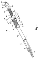
Figure 1 is a perspective view of a clamp assembly for a linear travel, self aligning, rotating retention clamp of the present disclosure;
Figure 2 is a bottom perspective view of a vehicular adapter assembly incorporating the clamp assembly ofFigure 1 ;
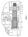
Figure 3 is a cross sectional side elevational view of the vehicular adapter assembly ofFigure 2 ;
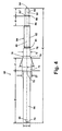
Figure 4 is a side elevational view of another embodiment of a clamp assembly of the present disclosure;
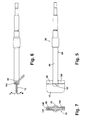
Figure 5 is a side elevational view of a subassembly including the clamp assembly ofFigure 4 having a flap member rotatably pinned thereto;
Figure 6 is a top elevational view of the subassembly ofFigure 5 ;
Figure 7 is an end elevational view of the subassembly ofFigure 5 ;
Figure 8 is a side elevational view of a flap of the present disclosure;
Figure 9 is a top elevational view of the flap ofFigure 8 ;
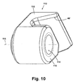
Figure 10 is a front perspective view of a clamping hook of the present disclosure;
Figure 11 is a side elevational view of the clamping hook ofFigure 10 ;
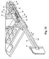
Figure 12 is a partial cross sectional side perspective view of a clamp assembly modified from the clamp assembly ofFigure 1 installed in the vehicular adapter assembly ofFigure 2 ;
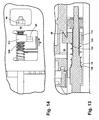
Figure 13 is a cross sectional side elevational view of the clamp assembly ofFigure 12 ; and
Figure 14 is a side elevational view of the clamp assembly ofFigure 13 shown prior to engagement of the clamping hook. - According to several embodiments of the present disclosure and referring generally to
Figure 1 , aclamp assembly 10 includes ascrew member 11 having aflap member 12 rotatably connected thereto. According to several embodiments,screw member 11 can include adrive member portion 14 provided from one of a plurality of geometric shapes which as shown in this view can include a polygonal shape having multiple sides such as the six-sided shape shown inFigure 1 .Screw member 11 can further include ashaft portion 16 connected to drivemember portion 14 having a substantially circular or tubular shape, which directly transitions into astop member 18. - An indexing
member 20 can be slidably positioned proximate to stopmember 18. Abiasing member 22 such as a coiled compression or torsion spring can be positioned betweenstop member 18 and indexingmember 20. According to several embodiments,biasing member 22 can include an extending rod orfirst leg 24 which is received in a firstleg receiving slot 25 ofstop member 18, and an opposed extending rod orsecond leg 26 received in a secondleg receiving slot 27 created in indexingmember 20.First leg 24 andsecond leg 26 of biasingmember 22 provide positive rotational engagement so that a rotational force applied toscrew member 11 is translated fromstop member 18 byfirst leg 24 through biasingmember 22 and throughsecond leg 26 to indexingmember 20, while biasingmember 22 can extend or compress with displacement of indexingmember 20. -
Biasing member 22 is freely disposed over a threadedportion 28 ofscrew member 11. Indexingmember 20 is similarly freely and slidably disposed over threadedportion 28 so that indexingmember 20 is free to longitudinally slide with respect to fixedstop member 18. Threadedportion 28 is provided with a plurality ofleft hand threads 29. A clamping member defining aclamping hook 30 having mating internal left hand threads is threadably engaged withleft hand threads 29 of threadedportion 28 and abuts indexingmember 20. - Screw
member 11 further includes asecond shaft portion 32 positioned between threadedportion 28 and a threadedend 34. Afirst washer 36 and asecond washer 38 are slidingly received at opposite ends ofsecond shaft portion 32. A fastener such as a torque nut, a nut fixed with a sealing compound, or a self locking nut, hereinafter generally referred to as aself locking nut 40 is threadably engaged with threadedend 34 and abutssecond washer 38 in an installed position ofclamp assembly 10 which is described in further detail in reference toFigure 2 . -
Flap member 12 is rotatably connected toscrew member 11 using aretention pin 41. A plurality offirst ratchet teeth 42 are provided at a clamping hook facing end of indexingmember 20.First ratchet teeth 42 engage individual ones of a plurality ofsecond ratchet teeth 43 provided onclamping hook 30.First ratchet teeth 42 can ratchet againstsecond ratchet teeth 43 in response to rotation ofscrew member 11 which by engagement withfirst leg 24 andsecond leg 26 of biasingmember 22 rotateindexing member 20 and thereby rotateclamping hook 30. Clampinghook 30 further provides acavity 44 defining anengagement face 46. - Referring now to
Figure 2 ,clamp assembly 10 is shown in an installed position in an assembly such as avehicular adapter assembly 48.Vehicular adapter assembly 48 can include acommunication device 50 such as a portable radio which is received within an enclosure member such as an enclosure such as acabinet 52 and clamped usingclamp assembly 10. Whencommunication device 50 is fully seated or installed incabinet 52,clamp assembly 10 is positioned as shown having first andsecond washers retention wall 54 ofcabinet 52.Self locking nut 40 is then threadably engaged with threadedend 34 to longitudinally fixclamp assembly 10 into the position shown, while permitting rotation ofscrew member 11 byflap member 12. - By rotating
screw member 11 usingflap member 12 in a clockwise engagement rotation direction "A",stop member 18 imparts a rotation force to clampinghook 30 through biasingmember 22 to rotateclamping hook 30 into the position shown.Engagement face 46 of clampinghook 30 engages with an engagement member such as anengagement wall 56 ofcommunication device 50. Further rotation ofscrew member 11 in the engagement rotation direction "A" translatesclamping hook 30 usingleft hand threads 29 in a hook engagement direction "B" to seat againstengagement wall 56. During this operation,first ratchet teeth 42 of indexingmember 20 rotating in response to rotational torque applied to biasingmember 22 ratchet with and therefore engage opposingsecond ratchet teeth 43 ofclamping hook 30 to position clampinghook 30 as shown in anaperture 57 ofcabinet 52 for subsequent engagement ofclamping hook 30 withengagement wall 56. As will be evident,flap member 12 is rotated to the position shown to maximize torque when rotatingscrew member 11.Flap member 12 can then be rotated (similar to the configuration shown in phantom inFigure 6 ) until it contacts drivemember portion 14 ofscrew member 11 which repositionsflap member 12 to provide additional access area forcommunication device 50. - Referring now to
Figure 3 , clampinghook 30 is shown positioned to allowengagement face 46 to contact anengagement face 58 defined within abody cavity 60 ofengagement wall 56. Clampinghook 30 is also positioned within aclamp cavity 62 defined by bothcommunication device 50 andcabinet 52. Clampinghook 30 is therefore free to rotate withinclamp cavity 62 and must be rotated into thebody cavity 60 as shown in order to permit engagement between engagement face 46 of clampinghook 30 and engagement face 58 ofengagement wall 56. In the fully installed position shown,self locking nut 40 abuts ashoulder 63 ofsecond shaft portion 32 allowingself locking nut 40 andscrew member 11 to co-rotate, withself locking nut 40 able to rotate with respect tosecond washer 38 which is substantially fixed against rotation by contact withretention wall 54.Second washer 38 therefore acts as a rotational bearing surface forself locking nut 40. Similarly,first washer 36 is non-rotatably fixed with respect toretention wall 54.Second shaft portion 32 is diametrically sized to provide a rotational clearance fit from an inner wall of an aperture provided inretention wall 54. - Referring now to
Figure 4 , according to additional embodiments of the present disclosure, ascrew member 64 is modified fromscrew member 11.Screw member 64 includes acylindrical portion 66 which replaces bothdrive member portion 14 andshaft portion 16 ofscrew member 11.Cylindrical portion 66 has a cylinder diameter "C" and a cylinder length "D" which can vary to suit the arrangement ofvehicular adapter assembly 48. Apin aperture 68 is provided proximate to afirst end 70 ofcylindrical portion 66 to receive a retention pin. Atransition portion 72 defining a tapering or a conical shape transitions fromcylindrical portion 66 to astop portion 74.Stop portion 74 is also cylindrical in shape, however, stopportion 74 includes a stop diameter "E" which is larger than cylinder diameter "C" for a function that will be described later herein.Stop portion 74 extends for a stop length "F" before transitioning into afirst sleeve portion 76 via ataper portion 78.Taper portion 78 is substantially conical shaped and extends to anend face 79 ofstop portion 74.End face 79 can be oriented perpendicular to alongitudinal axis 80 ofscrew member 64.Taper portion 78 defines an angle α which according to several embodiments can be approximately 40°, but can also vary between approximately 20° to approximately 120°.Stop portion 74 has a stop length "F" which can vary at the discretion of the manufacturer.First sleeve portion 76 has a sleeve diameter "G" which is sized to slidably receive a biasing member 126 (shown and described in reference toFigure 12 ). -
First sleeve portion 76 extends to a recessedthread stop 81 which separatesfirst sleeve portion 76 from a threadedportion 82. Threadedportion 82 has a plurality ofleft hand threads 84 similar in function toleft hand threads 29. Asecond sleeve portion 86 similar in diameter and function tosecond shaft portion 32 extends from threadedportion 82.Second sleeve portion 86 is unthreaded. A second recessedthread stop 88 is created betweensecond sleeve portion 86 and a second threadedportion 90. Second threadedportion 90 has a plurality ofright hand threads 92 also adapted to threadably receiveself locking nut 40. Second threadedportion 90 extends to asecond end 94 ofscrew member 64.Second sleeve portion 86 has a sleeve length "H" which corresponds approximately to a width ofretention wall 54 of cabinet 52 (shown inFigure 2 ) plus a combined thickness of first andsecond washers Screw member 64 has a total screw length "K" which can be the same or can vary from a length ofscrew member 11. - As best seen in reference to
Figure 5 , asubassembly 96 is created whenflap member 12 is pinned or otherwise rotatably connected tocylindrical portion 66 ofscrew member 64.Flap member 12 can include each of a first and secondpin receiving member pin receiving members screw member 64. - Referring now to
Figures 4 ,5, and 6 , to rotatablycouple flap member 12, aretention pin 102 similar toretention pin 41 is slidably inserted into firstpin receiving member 98, throughpin aperture 68 ofscrew member 64, and then is received in secondpin receiving member 100 offlap member 12.Retention pin 102 allowsflap member 12 to rotate about either of a first or second rotation direction "L" or "M" from the fully extended position shown to one of two stowed positions (one shown in phantom). - Referring now to
Figure 7 ,flap member 12 is created by bending or otherwise forming a first andsecond wing pin receiving members retention pin 102. First andsecond wings pin receiving members - Referring now generally to
Figures 8 and 9 ,flap member 12 has a height "N" and a width "P" which can vary at the discretion of the manufacturer. A screwmember clearance aperture 108 has a cavity height "Q" adapted to receivecylindrical portion 66 ofscrew member 64. Opposed corner relief(s) 110 can also be created either as substantially flat surfaces or as rounded corners of first andsecond wings flap member 12. Apin receiving aperture 111 having a pin receiving aperture diameter "R" substantially equal to or larger than a diameter of retention pin 102 (shown inFigure 6 ) is created in each of first and secondpin receiving members pin receiving aperture 111 of each of first and secondpin receiving members retention pin 102. - Referring now to
Figure 10 , aclamping hook 112 is modified from clampinghook 30 and includes abody 113 having a threadedaperture 114 with female left hand threads corresponding toleft hand threads 84 of screw member 64 (shown inFigure 4 ). Threadedaperture 114 is created on anaxis 115 which is co-axially alignable withlongitudinal axis 80 of screw member 64(shown inFigure 4 ). Engagement face 46' (similar toengagement face 46 of clamping hook 30) is created in ahook member 116 extending frombody 113. - Referring to
Figure 11 , clampinghook 112 includes a conical shapedextension 117 extending away from afirst surface 118.Body 113 has a body width "S" betweenfirst surface 118 and an opposedsecond surface 122. Clampinghook 112 has a total height "T".Conical extension 117 has a conical extension height "U" extending with respectfirst surface 118.Conical extension 117 has ataper surface 120.Taper surface 120 defines a taper angle β with respect to a reference line oriented substantially perpendicular tofirst surface 118. According to several embodiments, taper angle β can be approximately 20°, but can also vary between approximately 10° to approximately 60° and greater at the discretion of the manufacturer. - Referring to
Figure 12 , aclamp assembly 124 is modified fromclamp assembly 10.Clamp assembly 124 includesscrew member 64 havingflap member 12 rotatably connected thereto.Clamp assembly 124 also includes a biasingmember 126 which is modified from biasingmember 22 to eliminate each offirst leg 24 andsecond leg 26.Clamp assembly 124 further includes clampinghook 112, first andsecond washers self locking nut 40. - Operation of
clamp assembly 124 is similar to operation ofclamp assembly 10 with the following differences.Biasing member 126 includes afirst coil end 128 which engagestaper portion 78 ofscrew member 64. As previously discussed in reference toFigure 4 , stopmember 74 has stop diameter "E" which is larger than cylinder diameter "C" to provide radially outwardly extending material to establishtaper portion 78 which frictionally receivesfirst coil end 128.Biasing member 126 also includes asecond coil end 130 which engagestaper surface 120 of clampinghook 112. The friction betweenfirst coil end 128 andtaper portion 78 and betweensecond coil end 130 andtaper surface 120 provides the necessary frictional rotational engagement betweenscrew member 64 and clampinghook 112 to rotate clampinghook 112 into the position shown where clampinghook 112 can engageengagement face 58 ofvehicular adapter assembly 48 in the hook engagement direction "B".Taper portion 78 andtaper surface 120 also provide for self-alignment of biasingmember 126 to evenly and linearly distribute the rotational force imparted onscrew member 64 through biasingmember 126 as a combination of a rotational and a linear force to clampinghook 112. - Referring now to
Figure 13 , frictional engagement of biasingmember 126 to screwmember 64 is provided at each of thetaper portion 78 and thetaper surface 120 which cause each of the first and second coil ends 128, 130 of biasingmember 126 to expand radially outward with respect to the remaining coil members of biasingmember 126. This frictional engagement allows the first andsecond legs member 22 to be eliminated in biasingmember 126. With clampinghook 112 rotated intobody cavity 60 ofcabinet 52, clampinghook 112 is thereafter operable to engageengagement face 58 by rotation ofscrew member 64 usingflap member 12. - Referring now to
Figure 14 , a non-engaged orientation of clampinghook 112 is shown prior to rotation intobody cavity 60. Engagement face 46' ofhook member 116 is therefore positioned hanging substantially downward. Compression of biasingmember 126 generating an axial force and rotation ofscrew member 64 create frictional engagement betweenscrew member 64, biasingmember 126, and clampinghook 112 necessary to rotate clampinghook 112 intobody cavity 60 where clampinghook 112contacts communication device 50 which stops rotation of clampinghook 112. Further rotation ofscrew member 64drives clamping hook 112 in hook engagement direction "B" usingleft hand threads 84. -
Screw members flap member 12, clamping hooks 30 and 112, and indexingmember 20 of the present disclosure can be made of a corrosion resistant metal, such as corrosion resistant steel, which can be passivated or precipitation hardened.Biasing members - Clamp assemblies of the present disclosure offer several advantages. By using clamping hooks which can be positively or frictionally rotated by a biasing member, the clamping hooks can be positioned in multiple orientations on a threaded portion of the screw member, allowing the clamp assembly to be positioned in a corner or peripheral location about the cabinet. The biasing member also provides for reverse rotation of the clamping hook if necessary, to permit removal of the clamp assembly. Taper and conical surfaces which are used in conjunction with the biasing member in several embodiments allow the use of standard end-ground coil springs for the biasing members. Taper and conical surfaces described herein also promote self-alignment of the biasing members which promotes evenly-loaded, linear travel of the clamping hook to align the clamping hook for engagement.
Claims (9)
- A retention clamp, comprising:a shaft having a stop member and a first threaded portion, the first threaded portion including a left hand thread;a clamping member threadably connected to the first threaded portion; anda biasing member positioned between the stop member and the clamping member operable to transfer a rotational force applied to the shaft to the clamping member to rotate the clamping member into an engagement position.
- The retention clamp of Claim 1, further comprising a taper portion of the stop member operable to frictionally engage a first end of the biasing member.
- The retention clamp of Claim 2, further comprising a taper surface of the clamping member operable to frictionally engage a second end of the biasing member.
- The retention clamp of Claim 1, further comprising a second threaded portion of the shaft adapted to receive a nut.
- The retention clamp of Claim 4, further comprising a non-threaded sleeve portion of the shaft located between the first and second threaded portions operable as a rotational bearing surface for the shaft.
- The retention clamp of Claim 5, further comprising a recessed thread stop positioned between the first and second threaded portions of the shaft, the recessed thread stop defining a shoulder adapted to abuttingly engage the nut in a nut fully installed position, the nut in the fully installed position being substantially fixed for co-rotation with the shaft.
- The retention clamp of Claim 1, further comprising a flap member rotatably pinned to the shaft operable to increase a torque load applied to the shaft for manual rotation of the shaft.
- The retention clamp of Claim 1, further comprising an engagement surface of the clamping member angled with respect to a longitudinal axis of the shaft.
- A retention clamp system, comprising:an assembly including;a shaft having a stop member and a first threaded portion, the first threaded portion including a left hand thread;a clamping member threadably connected to the first threaded portion, the clamping member having an engagement surface angled with respect to a longitudinal axis of the shaft; anda biasing member positioned between the stop member and the clamping member operable to transfer a rotational force applied to the shaft to the clamping member to rotate the clamping member into an engagement position;an enclosure member adapted to fixedly receive the assembly; anda device adapted to be received in the enclosure, the device having an engagement post adapted to receive the engagement surface of the clamping member when the shaft is rotated.
Applications Claiming Priority (1)
| Application Number | Priority Date | Filing Date | Title |
|---|---|---|---|
| US11/799,056 US7896570B2 (en) | 2007-04-30 | 2007-04-30 | Linear travel, self aligning, rotating, retention clamp |
Publications (3)
| Publication Number | Publication Date |
|---|---|
| EP1988298A2 true EP1988298A2 (en) | 2008-11-05 |
| EP1988298A3 EP1988298A3 (en) | 2010-01-13 |
| EP1988298B1 EP1988298B1 (en) | 2011-06-08 |
Family
ID=39682610
Family Applications (1)
| Application Number | Title | Priority Date | Filing Date |
|---|---|---|---|
| EP08008297A Not-in-force EP1988298B1 (en) | 2007-04-30 | 2008-04-30 | Linear travel, self aligning, rotating, retention clamp |
Country Status (3)
| Country | Link |
|---|---|
| US (1) | US7896570B2 (en) |
| EP (1) | EP1988298B1 (en) |
| IL (1) | IL191029A0 (en) |
Cited By (1)
| Publication number | Priority date | Publication date | Assignee | Title |
|---|---|---|---|---|
| EP2154382A4 (en) * | 2007-05-08 | 2017-07-19 | Terumo Kabushiki Kaisha | Clamp device |
Families Citing this family (3)
| Publication number | Priority date | Publication date | Assignee | Title |
|---|---|---|---|---|
| US8578821B2 (en) | 2011-08-17 | 2013-11-12 | Hopkins Manufacturing Corporation | Oil filter wrench |
| US9945580B2 (en) * | 2012-08-28 | 2018-04-17 | Broan-Nutone, Llc | Ventilation system |
| US9454192B2 (en) * | 2014-03-29 | 2016-09-27 | Lenovo (Singapore) Pte. Ltd. | Component retention mechanism |
Family Cites Families (11)
| Publication number | Priority date | Publication date | Assignee | Title |
|---|---|---|---|---|
| US2734410A (en) * | 1956-02-14 | Gipperich | ||
| US1562951A (en) * | 1923-09-17 | 1925-11-24 | Heinn Company | Screw for loose-leaf binders |
| US1769332A (en) * | 1928-05-14 | 1930-07-01 | Fredrick W Coffing | Portable guy clamp |
| US2566064A (en) * | 1946-10-21 | 1951-08-28 | Gen Electric | Cabinet construction |
| US2855454A (en) * | 1953-10-29 | 1958-10-07 | Alden Milton | Housing for mounting electrical circuit components |
| US3012772A (en) * | 1958-07-17 | 1961-12-12 | Vlier Engineering Corp | Blind clamping device |
| US3199938A (en) * | 1963-08-05 | 1965-08-10 | Bailey Meter Co | Latch mechanism |
| CH600740A5 (en) * | 1976-04-28 | 1978-06-30 | Bbc Brown Boveri & Cie | |
| US6588711B2 (en) * | 1999-12-21 | 2003-07-08 | Masakatsu Onishi | Fastening fixture |
| EP1498571A1 (en) | 2003-07-14 | 2005-01-19 | Ronaldus Johannes Stienstra | Ladder safety device |
| US7401995B2 (en) * | 2005-03-31 | 2008-07-22 | Nissan Technical Center North America, Inc. | Channel connector |
-
2007
- 2007-04-30 US US11/799,056 patent/US7896570B2/en not_active Expired - Fee Related
-
2008
- 2008-04-27 IL IL191029A patent/IL191029A0/en unknown
- 2008-04-30 EP EP08008297A patent/EP1988298B1/en not_active Not-in-force
Cited By (1)
| Publication number | Priority date | Publication date | Assignee | Title |
|---|---|---|---|---|
| EP2154382A4 (en) * | 2007-05-08 | 2017-07-19 | Terumo Kabushiki Kaisha | Clamp device |
Also Published As
| Publication number | Publication date |
|---|---|
| EP1988298A3 (en) | 2010-01-13 |
| US20080267697A1 (en) | 2008-10-30 |
| IL191029A0 (en) | 2008-12-29 |
| US7896570B2 (en) | 2011-03-01 |
| EP1988298B1 (en) | 2011-06-08 |
Similar Documents
| Publication | Publication Date | Title |
|---|---|---|
| EP1807630B1 (en) | Rotatable captivated nut | |
| EP1988298B1 (en) | Linear travel, self aligning, rotating, retention clamp | |
| EP1131564B1 (en) | Screw connection | |
| EP3607213B1 (en) | Perforated wall system and fastening element | |
| JP2013536384A (en) | Cage nut | |
| EP1477690A2 (en) | Ball joint | |
| DE10052534A1 (en) | Fastening element has stop against which acts preloaded spring element, and coupling section on stop and reciprocal coupling section on gripping element form connection | |
| US6050766A (en) | Two part slip-on nut | |
| EP2226517A1 (en) | Construction unit | |
| US6672792B1 (en) | Tube fastener apparatus | |
| WO2020176724A1 (en) | Toggle cam bolt | |
| US12241494B2 (en) | Multi-piece bolts and methods of making the same | |
| EP2816243B1 (en) | Fastening element | |
| US10968940B2 (en) | High torque bolt | |
| AU2003213796A1 (en) | Set screw with rotating point | |
| EP2341256A2 (en) | Hook with spring and indicator | |
| DE9315601U1 (en) | Pipe screw connection with a support sleeve and a conical extension of the support sleeve on the inside | |
| US8790057B2 (en) | Threaded fastener | |
| CN207387529U (en) | multifunctional wrench | |
| US4476705A (en) | Automobile body dent puller | |
| CN220452404U (en) | Connection structure capable of triggering automatic clamping and manual locking | |
| DE102004012278B4 (en) | Rosette for a door fitting | |
| US20100067977A1 (en) | Fastener | |
| DE19808628A1 (en) | Lightweight rivet-like holding fixture for aircraft components | |
| CN208474429U (en) | Lead screw locks nut clamping device |
Legal Events
| Date | Code | Title | Description |
|---|---|---|---|
| PUAI | Public reference made under article 153(3) epc to a published international application that has entered the european phase |
Free format text: ORIGINAL CODE: 0009012 |
|
| 17P | Request for examination filed |
Effective date: 20080430 |
|
| AK | Designated contracting states |
Kind code of ref document: A2 Designated state(s): AT BE BG CH CY CZ DE DK EE ES FI FR GB GR HR HU IE IS IT LI LT LU LV MC MT NL NO PL PT RO SE SI SK TR |
|
| AX | Request for extension of the european patent |
Extension state: AL BA MK RS |
|
| PUAL | Search report despatched |
Free format text: ORIGINAL CODE: 0009013 |
|
| AK | Designated contracting states |
Kind code of ref document: A3 Designated state(s): AT BE BG CH CY CZ DE DK EE ES FI FR GB GR HR HU IE IS IT LI LT LU LV MC MT NL NO PL PT RO SE SI SK TR |
|
| AX | Request for extension of the european patent |
Extension state: AL BA MK RS |
|
| AKX | Designation fees paid |
Designated state(s): DE FR GB IT |
|
| RIC1 | Information provided on ipc code assigned before grant |
Ipc: F16B 2/12 20060101AFI20101022BHEP |
|
| GRAP | Despatch of communication of intention to grant a patent |
Free format text: ORIGINAL CODE: EPIDOSNIGR1 |
|
| GRAS | Grant fee paid |
Free format text: ORIGINAL CODE: EPIDOSNIGR3 |
|
| GRAA | (expected) grant |
Free format text: ORIGINAL CODE: 0009210 |
|
| AK | Designated contracting states |
Kind code of ref document: B1 Designated state(s): DE FR GB IT |
|
| REG | Reference to a national code |
Ref country code: GB Ref legal event code: FG4D |
|
| REG | Reference to a national code |
Ref country code: DE Ref legal event code: R096 Ref document number: 602008007393 Country of ref document: DE Effective date: 20110721 |
|
| PLBE | No opposition filed within time limit |
Free format text: ORIGINAL CODE: 0009261 |
|
| STAA | Information on the status of an ep patent application or granted ep patent |
Free format text: STATUS: NO OPPOSITION FILED WITHIN TIME LIMIT |
|
| 26N | No opposition filed |
Effective date: 20120309 |
|
| REG | Reference to a national code |
Ref country code: DE Ref legal event code: R097 Ref document number: 602008007393 Country of ref document: DE Effective date: 20120309 |
|
| REG | Reference to a national code |
Ref country code: FR Ref legal event code: PLFP Year of fee payment: 9 |
|
| PGFP | Annual fee paid to national office [announced via postgrant information from national office to epo] |
Ref country code: GB Payment date: 20160427 Year of fee payment: 9 Ref country code: DE Payment date: 20160427 Year of fee payment: 9 |
|
| PGFP | Annual fee paid to national office [announced via postgrant information from national office to epo] |
Ref country code: IT Payment date: 20160421 Year of fee payment: 9 Ref country code: FR Payment date: 20160425 Year of fee payment: 9 |
|
| REG | Reference to a national code |
Ref country code: DE Ref legal event code: R119 Ref document number: 602008007393 Country of ref document: DE |
|
| GBPC | Gb: european patent ceased through non-payment of renewal fee |
Effective date: 20170430 |
|
| REG | Reference to a national code |
Ref country code: FR Ref legal event code: ST Effective date: 20171229 |
|
| PG25 | Lapsed in a contracting state [announced via postgrant information from national office to epo] |
Ref country code: DE Free format text: LAPSE BECAUSE OF NON-PAYMENT OF DUE FEES Effective date: 20171103 Ref country code: FR Free format text: LAPSE BECAUSE OF NON-PAYMENT OF DUE FEES Effective date: 20170502 |
|
| PG25 | Lapsed in a contracting state [announced via postgrant information from national office to epo] |
Ref country code: GB Free format text: LAPSE BECAUSE OF NON-PAYMENT OF DUE FEES Effective date: 20170430 |
|
| PG25 | Lapsed in a contracting state [announced via postgrant information from national office to epo] |
Ref country code: IT Free format text: LAPSE BECAUSE OF NON-PAYMENT OF DUE FEES Effective date: 20170430 |