EP1988244B1 - Drive device for operating a vehicle door - Google Patents
Drive device for operating a vehicle door Download PDFInfo
- Publication number
- EP1988244B1 EP1988244B1 EP20070107270 EP07107270A EP1988244B1 EP 1988244 B1 EP1988244 B1 EP 1988244B1 EP 20070107270 EP20070107270 EP 20070107270 EP 07107270 A EP07107270 A EP 07107270A EP 1988244 B1 EP1988244 B1 EP 1988244B1
- Authority
- EP
- European Patent Office
- Prior art keywords
- drive device
- damping device
- intermediate gear
- housing part
- drive
- Prior art date
- Legal status (The legal status is an assumption and is not a legal conclusion. Google has not performed a legal analysis and makes no representation as to the accuracy of the status listed.)
- Revoked
Links
- 238000013016 damping Methods 0.000 claims description 37
- 229920001971 elastomer Polymers 0.000 claims description 11
- 230000005540 biological transmission Effects 0.000 claims description 5
- 238000009413 insulation Methods 0.000 claims description 5
- 230000008878 coupling Effects 0.000 claims description 4
- 238000010168 coupling process Methods 0.000 claims description 4
- 238000005859 coupling reaction Methods 0.000 claims description 4
- 239000002184 metal Substances 0.000 claims description 4
- 230000000295 complement effect Effects 0.000 claims description 2
- 239000006260 foam Substances 0.000 claims description 2
- 239000000806 elastomer Substances 0.000 description 6
- 229920002725 thermoplastic elastomer Polymers 0.000 description 5
- 238000004026 adhesive bonding Methods 0.000 description 2
- 239000000463 material Substances 0.000 description 2
- 238000004073 vulcanization Methods 0.000 description 2
- 229920002457 flexible plastic Polymers 0.000 description 1
Images

Classifications
-
- E—FIXED CONSTRUCTIONS
- E05—LOCKS; KEYS; WINDOW OR DOOR FITTINGS; SAFES
- E05F—DEVICES FOR MOVING WINGS INTO OPEN OR CLOSED POSITION; CHECKS FOR WINGS; WING FITTINGS NOT OTHERWISE PROVIDED FOR, CONCERNED WITH THE FUNCTIONING OF THE WING
- E05F15/00—Power-operated mechanisms for wings
- E05F15/60—Power-operated mechanisms for wings using electrical actuators
- E05F15/603—Power-operated mechanisms for wings using electrical actuators using rotary electromotors
- E05F15/611—Power-operated mechanisms for wings using electrical actuators using rotary electromotors for swinging wings
- E05F15/616—Power-operated mechanisms for wings using electrical actuators using rotary electromotors for swinging wings operated by push-pull mechanisms
- E05F15/622—Power-operated mechanisms for wings using electrical actuators using rotary electromotors for swinging wings operated by push-pull mechanisms using screw-and-nut mechanisms
-
- E—FIXED CONSTRUCTIONS
- E05—LOCKS; KEYS; WINDOW OR DOOR FITTINGS; SAFES
- E05Y—INDEXING SCHEME ASSOCIATED WITH SUBCLASSES E05D AND E05F, RELATING TO CONSTRUCTION ELEMENTS, ELECTRIC CONTROL, POWER SUPPLY, POWER SIGNAL OR TRANSMISSION, USER INTERFACES, MOUNTING OR COUPLING, DETAILS, ACCESSORIES, AUXILIARY OPERATIONS NOT OTHERWISE PROVIDED FOR, APPLICATION THEREOF
- E05Y2201/00—Constructional elements; Accessories therefor
- E05Y2201/60—Suspension or transmission members; Accessories therefor
- E05Y2201/622—Suspension or transmission members elements
- E05Y2201/71—Toothed gearing
- E05Y2201/72—Planetary gearing
-
- E—FIXED CONSTRUCTIONS
- E05—LOCKS; KEYS; WINDOW OR DOOR FITTINGS; SAFES
- E05Y—INDEXING SCHEME ASSOCIATED WITH SUBCLASSES E05D AND E05F, RELATING TO CONSTRUCTION ELEMENTS, ELECTRIC CONTROL, POWER SUPPLY, POWER SIGNAL OR TRANSMISSION, USER INTERFACES, MOUNTING OR COUPLING, DETAILS, ACCESSORIES, AUXILIARY OPERATIONS NOT OTHERWISE PROVIDED FOR, APPLICATION THEREOF
- E05Y2800/00—Details, accessories and auxiliary operations not otherwise provided for
- E05Y2800/20—Combinations of elements
- E05Y2800/23—Combinations of elements of elements of different categories
- E05Y2800/232—Combinations of elements of elements of different categories of motors and transmissions
-
- E—FIXED CONSTRUCTIONS
- E05—LOCKS; KEYS; WINDOW OR DOOR FITTINGS; SAFES
- E05Y—INDEXING SCHEME ASSOCIATED WITH SUBCLASSES E05D AND E05F, RELATING TO CONSTRUCTION ELEMENTS, ELECTRIC CONTROL, POWER SUPPLY, POWER SIGNAL OR TRANSMISSION, USER INTERFACES, MOUNTING OR COUPLING, DETAILS, ACCESSORIES, AUXILIARY OPERATIONS NOT OTHERWISE PROVIDED FOR, APPLICATION THEREOF
- E05Y2900/00—Application of doors, windows, wings or fittings thereof
- E05Y2900/50—Application of doors, windows, wings or fittings thereof for vehicles
- E05Y2900/53—Type of wing
- E05Y2900/546—Tailboards, tailgates or sideboards opening upwards
Definitions
- the invention relates to a drive device for operating the vehicle door, in particular the tailgate, of a motor vehicle, which contains an actuator, and preferably two connecting devices provided for connecting the actuator on the one hand to the vehicle door and on the other hand to the body of the motor vehicle, the actuator comprising a tubular housing in which at least two drive components, such as an electric motor provided with a housing part, shafts of the electric motor which are required for the transmission of rotational movement, an intermediate gear provided with a housing part and a spindle drive having a spindle bearing which is adjacent to the intermediate gear and is fastened to the tubular housing, are arranged consecutively axially.
- drive components such as an electric motor provided with a housing part, shafts of the electric motor which are required for the transmission of rotational movement
- an intermediate gear provided with a housing part
- a spindle drive having a spindle bearing which is adjacent to the intermediate gear and is fastened to the tubular housing
- a known drive device of this type serves in particular for opening and closing the tailgate of a motor vehicle and has the external form of a gas-strut or gas-filled spring, with the spindle drive which is arranged in the tubular housing being operatively connected to an active element, which can be moved telescopically out of the housing, in order to operate the vehicle door.
- a disadvantage of this known drive device is that the vibrations produced by the electric motor and/or the intermediate gear (structure-borne noise vibrations) are transmitted via the tubular housing of the actuator and the active element directly to the vehicle body or to the tailgate.
- the acoustically perceptible level which is already present due to other components of the vehicle rises further.
- DE 195 19 948 discloses an example of drive device for a vehicle door.
- One object of the present invention concerns a drive device for operating a vehicle door, in which a transmission of the vibrations produced in particular by the electric motor and/or the intermediate gear of the actuator to the body of the vehicle is avoided in a simple manner or is substantially reduced.
- the invention is essentially based on the concept that at least two consecutive drive components comprise between them at least one damping device for the insulation of structure-borne noise.
- a further damping device is arranged between the housing parts of the drive components and the tubular housing in such a manner that there is no direct contact, conducting structure-borne noise, between these housing parts and the tubular housing of the actuator.
- At least one damping device for the insulation of structure-borne noise is arranged between the housing part of the electric motor and the housing part of the intermediate gear and/or between the housing part of the intermediate gear and the spindle bearing, and/or at least one second damping device for the insulation of structure-borne noise is provided between the shafts of the electric motor, which are required for the transmission of rotational movement, and the intermediate gear and/or the output shaft of the intermediate gear and the spindle of the spindle drive or an adapter part connected at the spindle bearing.
- the first damping device is composed of two plate-like retaining elements which are generally composed of metal and between which an elastic element is arranged.
- the elastic element of the first damping device can be connected nonreleasably to the plate-like retaining elements, for example by means of vulcanization, adhesion or adhesive bonding.
- the first retaining element is connected to the housing part of the electric motor or to the housing part of the gear by means of a screw connection and has threaded bores into which screws are screwed and then connect the second retaining element and the elastic element to the first retaining element.
- the first damping device comprises the mutually facing housing parts of the electric motor and the intermediate gear or of the intermediate gear and the spindle bearing, which housing parts are designed in the form of gear wheels, with the one subassembly (for example the spindle bearing) having an first toothing and the respectively other subassembly (for example the intermediate gear) having an complementary toothing, so that the teeth of the adjacent subassemblies intermesh without coming into contact, and with the respective intermediate spaces between the teeth of the adjacent subassemblies being connected to one another by an elastic element.
- the one subassembly for example the spindle bearing
- the respectively other subassembly for example the intermediate gear
- the teeth and the elastic element can be designed in such a manner that the teeth come to bear against the adjacent teeth only if a certain torsional load is exceeded, in order to avoid overloading of the elastomer during the correct use of the drive device.
- the second damping device may be, for example, a torsionally elastic shaft coupling embodied as a toothed ring.
- the second damping device may also comprise a damping bushing with an internal and external bushing and an elastic element situated in between, the external bushing being formed by the shaft of one of the two adjacent subassemblies.
- Rubber or a flexible plastic in particular a thermoplastic elastomer (also referred to below as TPE elastomer) can be used as the elastic element.
- the entire actuator is also mounted elastically between the connecting devices and therefore additional absorbing of the structure-borne noise takes place.
- Fig. 1, 1 refers to a motor vehicle which has a tailgate 2 which can be pivoted by a drive device 3 according to the invention from a closed position into the opened position illustrated in Fig. 1 and, if appropriate, into the closed position again.
- the drive device 3 comprises an actuator 4 and two connecting devices (ball sockets of corresponding angle joints) 5, 6 via which the actuator 4 is connected on the one hand to the body 7 of the motor vehicle 1 and on the other hand to the tailgate 2.
- the tailgate 2 may also be pivoted by two drive devices.
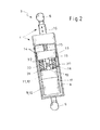
- the actuator 4 comprises a tubular housing 8 ( Fig. 2 ) in which a plurality of drive components are arranged consecutively axially. More precisly, the actuator 4 comprises consecutively on one axis an electric motor 10 provided with a housing part 9, an intermediate gear 12 provided with a housing part 11 and a spindle bearing 13 of a spindle drive 14, which spindle bearing is fastened to the tubular housing 8.
- the spindle 15 of the spindle drive 14 interacts with an axially guided spindle nut (not illustrated) which, for its part, axially displaces an active element 16 of the actuator 4, which active element acts on the tailgate 2 and can be pushed out of the housing 8 and retracted into it telescopically.
- damping device formed by an annular air gap 17 to remain between on the one hand the housing part 9 of the electric motor 10 and the housing part 11 of the intermediate gear 12 and on the other hand of the tubular housing 8 of the actuator 4, so that the structure-borne noise produced by the electric motor 10 or the gear 12 is not transmitted directly to the tubular housing 8.
- the damping device could be provided by a foam or/by an elastomer. Such a damping material can also be used advantageously to centre the electric motor 10 and the intermediate gear 12 in the tubular housing 8.
- a damping device 18 is provided between the housing part 11 of the intermediate gear 12 and the spindle bearing 13, and a second damping device 20 is provided between the output shaft 19 of the intermediate gear 12 and the spindle 15 of the spindle drive 14.
- the first damping device 18 comprises two plate-like retaining elements 21, 22 of metal between which an elastic element 23 of rubber or a suitable TPE elastomer is situated.
- the retaining elements 21, 22 and the elastic element 23 are connected to one another.
- the first retaining element 21 is connected to the housing part 11 of the intermediate gear 12 by means of a set of four screws 24.
- the screws 24 are mounted in corresponding depressions of the elastic element 23.
- the spindle bearing 13 is connected to the first damping device 18 by a second set of four long screws 25, these long screws 25 being screwed into threaded bores 26 of the second retaining element 22.
- the first damping device 18 can be a premanufactured element composed of two plate-like retaining elements and the elastic element is connected nonreleasably to the plate-like retaining elements, for example by means of vulcanization, adhesion or adhesive bonding.
- a screw connection between the plate-like retaining elements and the elastic element can also be realized to build the first damping device 18.
- a damping device 18 which is already premanufactured can also be connected directly to the housing of the intermediate gear 12 by means of screws, thus resulting in a unit which comprises electric motor 10, intermediate gear 12 and damping device 18 and is then screwed, for example from the inside of the housing of the spindle bearing 13 to the latter (i.e. with the spindle removed).
- the second damping device 20 comprises a torsionally elastic shaft coupling embodied as a toothed ring, with rubber or a TPE elastomer having preferably been used as the material for the shaft coupling.
- Figs 4 and 5 show a further exemplary embodiment of the invention. Also in this exemplary embodiment, the first and second damping devices 18', 20' are arranged between an intermediate gear (here a planetary gear) 12' and the spindle bearing 13' of a spindle drive.
- an intermediate gear here a planetary gear
- the mutually facing housing parts 11', 27 of the intermediate gear 12' and of the spindle bearing 13' are designed in the form of gear wheels, the spindle bearing 13' having an internal toothing and the intermediate gear 12' having an external toothing.
- the teeth 28, 29 of the adjacent subassemblies intermesh without coming into contact ( Fig. 5 ).
- the intermediate space remaining between the teeth 28, 29 is filled by an elastic element 30, for example of rubber or a TPE elastomer.
- the spindle bearing 13' is lengthened axially in the direction of the intermediate gear 12' by means of an adapter part 27 with an internal toothing.
- the adapter part 27 is fixed here to the spindle bearing 13' with the aid of screws 31 extending in the radial direction. So that the adapter part 27 does not transmit the full torsional load of, for example, 10 Nm to the screws 31, a toothing between spindle bearing 13' and adapter part 27 ensures a transmission of force in the tangential direction. Only small loads become effective radially.
- the adapter part and the adjoining region of the spindle bearing may also be formed as a single part. Provision may also be made to replace the screws by clips.
- a damping bushing with an internal and external bushing 32, 33 made in each case of metal and between which an elastic element 34 is arranged serves as the second damping device 20'.
- the external bushing 33 can be formed here, as illustrated in Figs 4 and 5 , by the output shaft 19 of the intermediate gear 12'.
Landscapes
- Gear Transmission (AREA)
- Power-Operated Mechanisms For Wings (AREA)
Description
- The invention relates to a drive device for operating the vehicle door, in particular the tailgate, of a motor vehicle, which contains an actuator, and preferably two connecting devices provided for connecting the actuator on the one hand to the vehicle door and on the other hand to the body of the motor vehicle, the actuator comprising a tubular housing in which at least two drive components, such as an electric motor provided with a housing part, shafts of the electric motor which are required for the transmission of rotational movement, an intermediate gear provided with a housing part and a spindle drive having a spindle bearing which is adjacent to the intermediate gear and is fastened to the tubular housing, are arranged consecutively axially.
- A known drive device of this type serves in particular for opening and closing the tailgate of a motor vehicle and has the external form of a gas-strut or gas-filled spring, with the spindle drive which is arranged in the tubular housing being operatively connected to an active element, which can be moved telescopically out of the housing, in order to operate the vehicle door.
- A disadvantage of this known drive device is that the vibrations produced by the electric motor and/or the intermediate gear (structure-borne noise vibrations) are transmitted via the tubular housing of the actuator and the active element directly to the vehicle body or to the tailgate. When such a drive device is fixed on the body of the vehicle or of the tailgate, the acoustically perceptible level which is already present due to other components of the vehicle rises further.
-
DE 195 19 948 discloses an example of drive device for a vehicle door. - One object of the present invention concerns a drive device for operating a vehicle door, in which a transmission of the vibrations produced in particular by the electric motor and/or the intermediate gear of the actuator to the body of the vehicle is avoided in a simple manner or is substantially reduced.
- This object is achieved according to the invention by the features of
Claim 1. Further particularly advantageous refinements of the invention are disclosed by the dependant claims. - The invention is essentially based on the concept that at least two consecutive drive components comprise between them at least one damping device for the insulation of structure-borne noise.
- Advantageously, a further damping device is arranged between the housing parts of the drive components and the tubular housing in such a manner that there is no direct contact, conducting structure-borne noise, between these housing parts and the tubular housing of the actuator.
- Advantageously, at least one damping device for the insulation of structure-borne noise is arranged between the housing part of the electric motor and the housing part of the intermediate gear and/or between the housing part of the intermediate gear and the spindle bearing, and/or at least one second damping device for the insulation of structure-borne noise is provided between the shafts of the electric motor, which are required for the transmission of rotational movement, and the intermediate gear and/or the output shaft of the intermediate gear and the spindle of the spindle drive or an adapter part connected at the spindle bearing.
- In a first embodiment of the invention, the first damping device is composed of two plate-like retaining elements which are generally composed of metal and between which an elastic element is arranged. In this case, the elastic element of the first damping device can be connected nonreleasably to the plate-like retaining elements, for example by means of vulcanization, adhesion or adhesive bonding.
- Furthermore it has proven advantageous if the first retaining element is connected to the housing part of the electric motor or to the housing part of the gear by means of a screw connection and has threaded bores into which screws are screwed and then connect the second retaining element and the elastic element to the first retaining element.
- In a further advantageous embodiment of the invention, the first damping device comprises the mutually facing housing parts of the electric motor and the intermediate gear or of the intermediate gear and the spindle bearing, which housing parts are designed in the form of gear wheels, with the one subassembly (for example the spindle bearing) having an first toothing and the respectively other subassembly (for example the intermediate gear) having an complementary toothing, so that the teeth of the adjacent subassemblies intermesh without coming into contact, and with the respective intermediate spaces between the teeth of the adjacent subassemblies being connected to one another by an elastic element.
- The teeth and the elastic element can be designed in such a manner that the teeth come to bear against the adjacent teeth only if a certain torsional load is exceeded, in order to avoid overloading of the elastomer during the correct use of the drive device.
- The second damping device may be, for example, a torsionally elastic shaft coupling embodied as a toothed ring. However, the second damping device may also comprise a damping bushing with an internal and external bushing and an elastic element situated in between, the external bushing being formed by the shaft of one of the two adjacent subassemblies.
- Rubber or a flexible plastic, in particular a thermoplastic elastomer (also referred to below as TPE elastomer) can be used as the elastic element.
- Finally, it may also be provided that, in addition to the insulation of the structure-borne noise between the individual subassemblies of the actuator, the entire actuator is also mounted elastically between the connecting devices and therefore additional absorbing of the structure-borne noise takes place.
- Further details and advantages of the invention emerge from the following exemplary embodiments explained with reference to figures, in which:
-
Fig. 1 shows a schematic perspective view of the rear region of a motor vehicle with the tailgate opened and a drive device according to the invention arranged at the side; -
Fig. 2 shows an enlarged illustration of the drive device according to the invention, which is only illustrated schematically inFig. 1 ; -
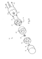
Fig. 3 shows an exploded illustration of the first damping device, illustrated inFig. 2 , with the adjacent subassemblies of the actuator; -
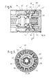
Fig. 4 shows a detail, reproduced as a longitudinal section, of a second exemplary embodiment of a drive device according to the invention, and -
Fig. 5 shows a cross section of the actuator illustrated inFig. 4 , along the section line referred to there by V-V. - In
Fig. 1, 1 refers to a motor vehicle which has atailgate 2 which can be pivoted by adrive device 3 according to the invention from a closed position into the opened position illustrated inFig. 1 and, if appropriate, into the closed position again. - The
drive device 3 comprises an actuator 4 and two connecting devices (ball sockets of corresponding angle joints) 5, 6 via which the actuator 4 is connected on the one hand to thebody 7 of themotor vehicle 1 and on the other hand to thetailgate 2. Thetailgate 2 may also be pivoted by two drive devices. - The actuator 4 comprises a tubular housing 8 (
Fig. 2 ) in which a plurality of drive components are arranged consecutively axially. More precisly, the actuator 4 comprises consecutively on one axis an electric motor 10 provided with a housing part 9, anintermediate gear 12 provided with ahousing part 11 and a spindle bearing 13 of aspindle drive 14, which spindle bearing is fastened to thetubular housing 8. Thespindle 15 of thespindle drive 14 interacts with an axially guided spindle nut (not illustrated) which, for its part, axially displaces anactive element 16 of the actuator 4, which active element acts on thetailgate 2 and can be pushed out of thehousing 8 and retracted into it telescopically. - According to the invention, provision is firstly made for damping device formed by an
annular air gap 17 to remain between on the one hand the housing part 9 of the electric motor 10 and thehousing part 11 of theintermediate gear 12 and on the other hand of thetubular housing 8 of the actuator 4, so that the structure-borne noise produced by the electric motor 10 or thegear 12 is not transmitted directly to thetubular housing 8. - Instead of the annular air gap, the damping device could be provided by a foam or/by an elastomer. Such a damping material can also be used advantageously to centre the electric motor 10 and the
intermediate gear 12 in thetubular housing 8. - Secondly, a
damping device 18 is provided between thehousing part 11 of theintermediate gear 12 and the spindle bearing 13, and asecond damping device 20 is provided between theoutput shaft 19 of theintermediate gear 12 and thespindle 15 of thespindle drive 14. - The
first damping device 18 comprises two plate-like retaining elements elastic element 23 of rubber or a suitable TPE elastomer is situated. As can be gathered fromFig. 3 , theretaining elements elastic element 23 are connected to one another. In this case, thefirst retaining element 21 is connected to thehousing part 11 of theintermediate gear 12 by means of a set of fourscrews 24. Thescrews 24 are mounted in corresponding depressions of theelastic element 23. - The spindle bearing 13 is connected to the
first damping device 18 by a second set of fourlong screws 25, theselong screws 25 being screwed into threadedbores 26 of thesecond retaining element 22. - The
first damping device 18 can be a premanufactured element composed of two plate-like retaining elements and the elastic element is connected nonreleasably to the plate-like retaining elements, for example by means of vulcanization, adhesion or adhesive bonding. However, a screw connection between the plate-like retaining elements and the elastic element can also be realized to build thefirst damping device 18. - Of course, a
damping device 18 which is already premanufactured can also be connected directly to the housing of theintermediate gear 12 by means of screws, thus resulting in a unit which comprises electric motor 10,intermediate gear 12 anddamping device 18 and is then screwed, for example from the inside of the housing of the spindle bearing 13 to the latter (i.e. with the spindle removed). - The
second damping device 20 comprises a torsionally elastic shaft coupling embodied as a toothed ring, with rubber or a TPE elastomer having preferably been used as the material for the shaft coupling. -
Figs 4 and 5 show a further exemplary embodiment of the invention. Also in this exemplary embodiment, the first and second damping devices 18', 20' are arranged between an intermediate gear (here a planetary gear) 12' and the spindle bearing 13' of a spindle drive. - In this exemplary embodiment, the mutually facing
housing parts 11', 27 of the intermediate gear 12' and of the spindle bearing 13' are designed in the form of gear wheels, the spindle bearing 13' having an internal toothing and the intermediate gear 12' having an external toothing. Theteeth 28, 29 of the adjacent subassemblies intermesh without coming into contact (Fig. 5 ). The intermediate space remaining between theteeth 28, 29 is filled by anelastic element 30, for example of rubber or a TPE elastomer. - In the case of the exemplary embodiment illustrated in
Figs 4 and 5 , the spindle bearing 13' is lengthened axially in the direction of the intermediate gear 12' by means of anadapter part 27 with an internal toothing. Theadapter part 27 is fixed here to the spindle bearing 13' with the aid ofscrews 31 extending in the radial direction. So that theadapter part 27 does not transmit the full torsional load of, for example, 10 Nm to thescrews 31, a toothing between spindle bearing 13' andadapter part 27 ensures a transmission of force in the tangential direction. Only small loads become effective radially. - Of course, the adapter part and the adjoining region of the spindle bearing may also be formed as a single part. Provision may also be made to replace the screws by clips.
- In this exemplary embodiment, a damping bushing with an internal and
external bushing elastic element 34 is arranged serves as the second damping device 20'. Theexternal bushing 33 can be formed here, as illustrated inFigs 4 and 5 , by theoutput shaft 19 of the intermediate gear 12'.
Claims (14)
- Drive device for operating the vehicle door (2), in particular the tailgate, of a motor vehicle (1), which contains an actuator (4) connected to the vehicle door (2) and to the body (7) of the motor vehicle (1), the actuator (4) comprising a tubular housing (8) in which at least an electric motor (10), an intermediate gear (12;12') and a spindle bearing (12;13';27) are arranged consecutively axially, characterized in that at least one damping device (18; 18 ; 20; 20') is provided between a housing part (11; 11') of the intermediate gear (12; 12') and the spindle bearing (13; 13'; 27) or between a housing part (9) of the electric motor (10) and a housing part (11; 11') of the intermediate gear (12; 12`), for the insulation of structure-borne noise.
- Drive device according to Claim 1, characterized in that a further damping device (17) is arranged between the drive components (10; 12; 12') provided with a housing part (9; 11; 11') and the tubular housing (8) in a manner insulating structure-borne noise.
- Drive device according to Claim 2, characterized in that the further damping device (17) is formed by an air gap or by a foam.
- Drive device according to one of previous claims, characterized in that the damping device (18`) comprises the mutually facing housing parts (27, 11') of the intermediate gear (12') and of the spindle bearing (13'), these housing parts (27, 11') being designed in the form of gear wheels in such a manner that the one subassembly (13', 27) has a first toothing and the respectively adjacent subassembly (12') has a complementary toothing, so that the teeth (28, 29) of the two subassemblies (12', 13') intermesh without coming into contact, and in that the respective intermediate spaces between the teeth (28, 29) of adjacent subassemblies (12', 13') are connected to one another by an elastic element (30).
- Drive device according to one of Claim 1 to 4, characterized in that at least one damping device (20; 20') is provided between the shafts of the electric motor (10), which are required for the transmission of rotational movement, and the intermediate gear (12; 12').
- Drive device according to one of Claim 1 to 5, characterized in that at least one damping device (20; 20') is provided between the output shaft (19) of the intermediate gear (12; 12') and the spindle (15) of the spindle drive (14).
- Drive device according to one of Claims 5 or 6, characterized in that the damping device (20) comprises a torsionally elastic shaft coupling embodied as a toothed ring.
- Drive device according to one of Claims 5 or 6, characterized in that the damping device (20') comprises a damping bushing with an internal bushing (32) and an external bushing (33) and an elastic element (34) situated in between, the external bushing (33) being formed by the shaft of one of the two adjacent subassemblies (12').
- Drive device according to anyone of previous Claims, characterized in that the damping device (18) comprises two plate-like retaining elements (21, 22) between which an elastic element (23) is arranged.
- Drive device according to Claim 9, characterized in that the retaining elements (21, 22) are composed of metal.
- Drive device according to one of Claim 9 or 10, characterized in that the elastic element (23; 30; 34) is composed of rubber or a fable plastic.
- Drive device according to one of Claim 8 to 11, characterized in that the elastic element (23) of the damping device (18) is connected nonreleasably to the plate-like retaining elements (21, 22).
- Drive device according to one of Claim 8 to 12, characterized in that the first retaining elements (21) is connected to the housing part (9) of the electric motor (10) or to the housing part (11) of the intermediate gear (12) by means of a first screw connection and the second retaining element (22) is connected to the spindle bearing (13) by means of a second screw connection (25).
- Drive device according to one of previous Claims, characterized in that the entire actuator (4) is mounted elastically between two connecting devices (5, 6).
Priority Applications (2)
| Application Number | Priority Date | Filing Date | Title |
|---|---|---|---|
| EP20070107270 EP1988244B1 (en) | 2007-04-30 | 2007-04-30 | Drive device for operating a vehicle door |
| PCT/EP2008/055289 WO2008132220A1 (en) | 2007-04-30 | 2008-04-29 | Drive device for operating a vehicle door |
Applications Claiming Priority (1)
| Application Number | Priority Date | Filing Date | Title |
|---|---|---|---|
| EP20070107270 EP1988244B1 (en) | 2007-04-30 | 2007-04-30 | Drive device for operating a vehicle door |
Publications (2)
| Publication Number | Publication Date |
|---|---|
| EP1988244A1 EP1988244A1 (en) | 2008-11-05 |
| EP1988244B1 true EP1988244B1 (en) | 2013-06-26 |
Family
ID=38519744
Family Applications (1)
| Application Number | Title | Priority Date | Filing Date |
|---|---|---|---|
| EP20070107270 Revoked EP1988244B1 (en) | 2007-04-30 | 2007-04-30 | Drive device for operating a vehicle door |
Country Status (2)
| Country | Link |
|---|---|
| EP (1) | EP1988244B1 (en) |
| WO (1) | WO2008132220A1 (en) |
Families Citing this family (1)
| Publication number | Priority date | Publication date | Assignee | Title |
|---|---|---|---|---|
| CN109972962A (en) * | 2019-04-03 | 2019-07-05 | 亚萨合莱自动门系统有限公司 | Automatic door operator and its transmission mechanism |
Family Cites Families (4)
| Publication number | Priority date | Publication date | Assignee | Title |
|---|---|---|---|---|
| DE19519948A1 (en) * | 1995-06-03 | 1996-12-12 | Beikirch Industrieelektronik G | Electrical reciprocal-action push-pull spindle drive |
| US6195940B1 (en) * | 1997-10-22 | 2001-03-06 | Saturn Electronics & Engineering, Inc. | Power actuator for a vehicle window |
| CA2514670A1 (en) * | 2004-08-06 | 2006-02-06 | Magna Closures Inc. | Electromechanical strut |
| DE102005047309A1 (en) * | 2005-09-30 | 2007-04-05 | Kirchhoff Gmbh & Co. Kg | Device for opening and closing car body panels, has drive shaft, which is divided in two shaft parts, whose one side is engaged with drive or transmission system and on other side with component of link chain or fitting parts |
-
2007
- 2007-04-30 EP EP20070107270 patent/EP1988244B1/en not_active Revoked
-
2008
- 2008-04-29 WO PCT/EP2008/055289 patent/WO2008132220A1/en not_active Ceased
Also Published As
| Publication number | Publication date |
|---|---|
| EP1988244A1 (en) | 2008-11-05 |
| WO2008132220A1 (en) | 2008-11-06 |
Similar Documents
| Publication | Publication Date | Title |
|---|---|---|
| KR101450326B1 (en) | Belt Type Driveline and Rack Assist Type Electric Power Steering Apparatus having The Same | |
| EP1760368B1 (en) | Electric Power Steering Apparatus | |
| JP5048804B2 (en) | Power steering device | |
| US20140352468A1 (en) | Reducer of electric power steering apparatus | |
| US20120322566A1 (en) | Reducer of electric power steering system | |
| US9976332B2 (en) | Electromechanical strut with integrated flex coupling and slip device and clutch/coupling assembly therefor | |
| KR101454505B1 (en) | Rack Assist Type Electric Power Steering Apparatus | |
| KR101560980B1 (en) | Power Transmission Device of Electric Power Steering Apparatus | |
| EP2564085B1 (en) | Elastic rotary actuator, particularly for robotic applications, provided with a damping device | |
| CN102046906B (en) | Motor vehicle door lock | |
| CN101512192B (en) | Transmission device | |
| GB2163108A (en) | Power-assisted steering mechanism | |
| US7098562B2 (en) | Ambidextrous electronic window lift motor | |
| EP1777140A1 (en) | Tensioner for belt-type transmission and electric power steering apparatus having the same | |
| KR20110060816A (en) | Rack-Driven Power Assist Steering | |
| EP1988244A1 (en) | Drive device for operating a vehicle door | |
| JP4487970B2 (en) | Electric power steering apparatus and motor for electric power steering apparatus | |
| CN113474235A (en) | Power assisted steering system for a motor vehicle | |
| KR20080061529A (en) | Worm shaft play compensator of electric power steering system | |
| JP2014040868A (en) | Shaft connecting mechanism | |
| WO2004033269A3 (en) | A feedback assembly for an electronically controlled electro-mechanical actuating unit for a motor vehicle | |
| CN207835285U (en) | A kind of motor shaft structure and automotive window motor | |
| EP1988243A1 (en) | Drive device for operating a vehicle door | |
| KR100651139B1 (en) | Double Pinion Type Electric Power Assist Steering | |
| JP3923356B2 (en) | Electric power steering device |
Legal Events
| Date | Code | Title | Description |
|---|---|---|---|
| PUAI | Public reference made under article 153(3) epc to a published international application that has entered the european phase |
Free format text: ORIGINAL CODE: 0009012 |
|
| AK | Designated contracting states |
Kind code of ref document: A1 Designated state(s): AT BE BG CH CY CZ DE DK EE ES FI FR GB GR HU IE IS IT LI LT LU LV MC MT NL PL PT RO SE SI SK TR |
|
| AX | Request for extension of the european patent |
Extension state: AL BA HR MK RS |
|
| 17P | Request for examination filed |
Effective date: 20090506 |
|
| 17Q | First examination report despatched |
Effective date: 20090605 |
|
| AKX | Designation fees paid |
Designated state(s): AT BE BG CH CY CZ DE DK EE ES FI FR GB GR HU IE IS IT LI LT LU LV MC MT NL PL PT RO SE SI SK TR |
|
| GRAP | Despatch of communication of intention to grant a patent |
Free format text: ORIGINAL CODE: EPIDOSNIGR1 |
|
| RIN1 | Information on inventor provided before grant (corrected) |
Inventor name: ORTH, DIETMAR C/O VALEOSECURITE HABITACLE Inventor name: KUMMER, FRANK C/O VALEOSECURITE HABITACLE |
|
| GRAS | Grant fee paid |
Free format text: ORIGINAL CODE: EPIDOSNIGR3 |
|
| GRAA | (expected) grant |
Free format text: ORIGINAL CODE: 0009210 |
|
| AK | Designated contracting states |
Kind code of ref document: B1 Designated state(s): AT BE BG CH CY CZ DE DK EE ES FI FR GB GR HU IE IS IT LI LT LU LV MC MT NL PL PT RO SE SI SK TR |
|
| REG | Reference to a national code |
Ref country code: GB Ref legal event code: FG4D |
|
| REG | Reference to a national code |
Ref country code: CH Ref legal event code: EP |
|
| REG | Reference to a national code |
Ref country code: AT Ref legal event code: REF Ref document number: 618783 Country of ref document: AT Kind code of ref document: T Effective date: 20130715 |
|
| REG | Reference to a national code |
Ref country code: IE Ref legal event code: FG4D |
|
| REG | Reference to a national code |
Ref country code: DE Ref legal event code: R096 Ref document number: 602007031225 Country of ref document: DE Effective date: 20130822 |
|
| PG25 | Lapsed in a contracting state [announced via postgrant information from national office to epo] |
Ref country code: SE Free format text: LAPSE BECAUSE OF FAILURE TO SUBMIT A TRANSLATION OF THE DESCRIPTION OR TO PAY THE FEE WITHIN THE PRESCRIBED TIME-LIMIT Effective date: 20130626 Ref country code: GR Free format text: LAPSE BECAUSE OF FAILURE TO SUBMIT A TRANSLATION OF THE DESCRIPTION OR TO PAY THE FEE WITHIN THE PRESCRIBED TIME-LIMIT Effective date: 20130927 Ref country code: FI Free format text: LAPSE BECAUSE OF FAILURE TO SUBMIT A TRANSLATION OF THE DESCRIPTION OR TO PAY THE FEE WITHIN THE PRESCRIBED TIME-LIMIT Effective date: 20130626 Ref country code: LT Free format text: LAPSE BECAUSE OF FAILURE TO SUBMIT A TRANSLATION OF THE DESCRIPTION OR TO PAY THE FEE WITHIN THE PRESCRIBED TIME-LIMIT Effective date: 20130626 Ref country code: SI Free format text: LAPSE BECAUSE OF FAILURE TO SUBMIT A TRANSLATION OF THE DESCRIPTION OR TO PAY THE FEE WITHIN THE PRESCRIBED TIME-LIMIT Effective date: 20130626 |
|
| REG | Reference to a national code |
Ref country code: AT Ref legal event code: MK05 Ref document number: 618783 Country of ref document: AT Kind code of ref document: T Effective date: 20130626 |
|
| REG | Reference to a national code |
Ref country code: LT Ref legal event code: MG4D |
|
| PG25 | Lapsed in a contracting state [announced via postgrant information from national office to epo] |
Ref country code: BG Free format text: LAPSE BECAUSE OF FAILURE TO SUBMIT A TRANSLATION OF THE DESCRIPTION OR TO PAY THE FEE WITHIN THE PRESCRIBED TIME-LIMIT Effective date: 20130926 |
|
| REG | Reference to a national code |
Ref country code: NL Ref legal event code: VDEP Effective date: 20130626 |
|
| PG25 | Lapsed in a contracting state [announced via postgrant information from national office to epo] |
Ref country code: LV Free format text: LAPSE BECAUSE OF FAILURE TO SUBMIT A TRANSLATION OF THE DESCRIPTION OR TO PAY THE FEE WITHIN THE PRESCRIBED TIME-LIMIT Effective date: 20130626 |
|
| PG25 | Lapsed in a contracting state [announced via postgrant information from national office to epo] |
Ref country code: AT Free format text: LAPSE BECAUSE OF FAILURE TO SUBMIT A TRANSLATION OF THE DESCRIPTION OR TO PAY THE FEE WITHIN THE PRESCRIBED TIME-LIMIT Effective date: 20130626 Ref country code: PT Free format text: LAPSE BECAUSE OF FAILURE TO SUBMIT A TRANSLATION OF THE DESCRIPTION OR TO PAY THE FEE WITHIN THE PRESCRIBED TIME-LIMIT Effective date: 20131028 Ref country code: BE Free format text: LAPSE BECAUSE OF FAILURE TO SUBMIT A TRANSLATION OF THE DESCRIPTION OR TO PAY THE FEE WITHIN THE PRESCRIBED TIME-LIMIT Effective date: 20130626 Ref country code: IS Free format text: LAPSE BECAUSE OF FAILURE TO SUBMIT A TRANSLATION OF THE DESCRIPTION OR TO PAY THE FEE WITHIN THE PRESCRIBED TIME-LIMIT Effective date: 20131026 Ref country code: SK Free format text: LAPSE BECAUSE OF FAILURE TO SUBMIT A TRANSLATION OF THE DESCRIPTION OR TO PAY THE FEE WITHIN THE PRESCRIBED TIME-LIMIT Effective date: 20130626 Ref country code: CZ Free format text: LAPSE BECAUSE OF FAILURE TO SUBMIT A TRANSLATION OF THE DESCRIPTION OR TO PAY THE FEE WITHIN THE PRESCRIBED TIME-LIMIT Effective date: 20130626 Ref country code: CY Free format text: LAPSE BECAUSE OF FAILURE TO SUBMIT A TRANSLATION OF THE DESCRIPTION OR TO PAY THE FEE WITHIN THE PRESCRIBED TIME-LIMIT Effective date: 20130619 Ref country code: EE Free format text: LAPSE BECAUSE OF FAILURE TO SUBMIT A TRANSLATION OF THE DESCRIPTION OR TO PAY THE FEE WITHIN THE PRESCRIBED TIME-LIMIT Effective date: 20130626 |
|
| PG25 | Lapsed in a contracting state [announced via postgrant information from national office to epo] |
Ref country code: PL Free format text: LAPSE BECAUSE OF FAILURE TO SUBMIT A TRANSLATION OF THE DESCRIPTION OR TO PAY THE FEE WITHIN THE PRESCRIBED TIME-LIMIT Effective date: 20130626 Ref country code: NL Free format text: LAPSE BECAUSE OF FAILURE TO SUBMIT A TRANSLATION OF THE DESCRIPTION OR TO PAY THE FEE WITHIN THE PRESCRIBED TIME-LIMIT Effective date: 20130626 Ref country code: ES Free format text: LAPSE BECAUSE OF FAILURE TO SUBMIT A TRANSLATION OF THE DESCRIPTION OR TO PAY THE FEE WITHIN THE PRESCRIBED TIME-LIMIT Effective date: 20131007 Ref country code: RO Free format text: LAPSE BECAUSE OF FAILURE TO SUBMIT A TRANSLATION OF THE DESCRIPTION OR TO PAY THE FEE WITHIN THE PRESCRIBED TIME-LIMIT Effective date: 20130626 |
|
| PG25 | Lapsed in a contracting state [announced via postgrant information from national office to epo] |
Ref country code: CY Free format text: LAPSE BECAUSE OF FAILURE TO SUBMIT A TRANSLATION OF THE DESCRIPTION OR TO PAY THE FEE WITHIN THE PRESCRIBED TIME-LIMIT Effective date: 20130626 |
|
| PLBI | Opposition filed |
Free format text: ORIGINAL CODE: 0009260 |
|
| PLAX | Notice of opposition and request to file observation + time limit sent |
Free format text: ORIGINAL CODE: EPIDOSNOBS2 |
|
| PG25 | Lapsed in a contracting state [announced via postgrant information from national office to epo] |
Ref country code: DK Free format text: LAPSE BECAUSE OF FAILURE TO SUBMIT A TRANSLATION OF THE DESCRIPTION OR TO PAY THE FEE WITHIN THE PRESCRIBED TIME-LIMIT Effective date: 20130626 |
|
| 26 | Opposition filed |
Opponent name: BROSE FAHRZEUGTEILE GMBH & CO. KG, HALLSTADT Effective date: 20140326 |
|
| PG25 | Lapsed in a contracting state [announced via postgrant information from national office to epo] |
Ref country code: IT Free format text: LAPSE BECAUSE OF FAILURE TO SUBMIT A TRANSLATION OF THE DESCRIPTION OR TO PAY THE FEE WITHIN THE PRESCRIBED TIME-LIMIT Effective date: 20130626 |
|
| REG | Reference to a national code |
Ref country code: DE Ref legal event code: R026 Ref document number: 602007031225 Country of ref document: DE Effective date: 20140326 |
|
| PLBB | Reply of patent proprietor to notice(s) of opposition received |
Free format text: ORIGINAL CODE: EPIDOSNOBS3 |
|
| RAP2 | Party data changed (patent owner data changed or rights of a patent transferred) |
Owner name: U-SHIN DEUTSCHLAND ZUGANGSSYSTEME GMBH |
|
| PG25 | Lapsed in a contracting state [announced via postgrant information from national office to epo] |
Ref country code: LU Free format text: LAPSE BECAUSE OF FAILURE TO SUBMIT A TRANSLATION OF THE DESCRIPTION OR TO PAY THE FEE WITHIN THE PRESCRIBED TIME-LIMIT Effective date: 20140430 Ref country code: MC Free format text: LAPSE BECAUSE OF FAILURE TO SUBMIT A TRANSLATION OF THE DESCRIPTION OR TO PAY THE FEE WITHIN THE PRESCRIBED TIME-LIMIT Effective date: 20130626 |
|
| REG | Reference to a national code |
Ref country code: CH Ref legal event code: PL |
|
| REG | Reference to a national code |
Ref country code: IE Ref legal event code: MM4A |
|
| REG | Reference to a national code |
Ref country code: DE Ref legal event code: R081 Ref document number: 602007031225 Country of ref document: DE Owner name: U-SHIN DEUTSCHLAND ZUGANGSSYSTEME GMBH, DE Free format text: FORMER OWNER: VALEO SICHERHEITSSYSTEME GMBH, 85253 ERDWEG, DE Effective date: 20141219 |
|
| PG25 | Lapsed in a contracting state [announced via postgrant information from national office to epo] |
Ref country code: CH Free format text: LAPSE BECAUSE OF NON-PAYMENT OF DUE FEES Effective date: 20140430 Ref country code: LI Free format text: LAPSE BECAUSE OF NON-PAYMENT OF DUE FEES Effective date: 20140430 |
|
| PG25 | Lapsed in a contracting state [announced via postgrant information from national office to epo] |
Ref country code: IE Free format text: LAPSE BECAUSE OF NON-PAYMENT OF DUE FEES Effective date: 20140430 |
|
| PG25 | Lapsed in a contracting state [announced via postgrant information from national office to epo] |
Ref country code: MT Free format text: LAPSE BECAUSE OF FAILURE TO SUBMIT A TRANSLATION OF THE DESCRIPTION OR TO PAY THE FEE WITHIN THE PRESCRIBED TIME-LIMIT Effective date: 20130626 |
|
| REG | Reference to a national code |
Ref country code: FR Ref legal event code: PLFP Year of fee payment: 10 |
|
| RDAF | Communication despatched that patent is revoked |
Free format text: ORIGINAL CODE: EPIDOSNREV1 |
|
| REG | Reference to a national code |
Ref country code: DE Ref legal event code: R103 Ref document number: 602007031225 Country of ref document: DE Ref country code: DE Ref legal event code: R064 Ref document number: 602007031225 Country of ref document: DE |
|
| PG25 | Lapsed in a contracting state [announced via postgrant information from national office to epo] |
Ref country code: TR Free format text: LAPSE BECAUSE OF FAILURE TO SUBMIT A TRANSLATION OF THE DESCRIPTION OR TO PAY THE FEE WITHIN THE PRESCRIBED TIME-LIMIT Effective date: 20130626 Ref country code: HU Free format text: LAPSE BECAUSE OF FAILURE TO SUBMIT A TRANSLATION OF THE DESCRIPTION OR TO PAY THE FEE WITHIN THE PRESCRIBED TIME-LIMIT; INVALID AB INITIO Effective date: 20070430 |
|
| PGFP | Annual fee paid to national office [announced via postgrant information from national office to epo] |
Ref country code: GB Payment date: 20160418 Year of fee payment: 10 Ref country code: DE Payment date: 20160413 Year of fee payment: 10 |
|
| PGFP | Annual fee paid to national office [announced via postgrant information from national office to epo] |
Ref country code: FR Payment date: 20160428 Year of fee payment: 10 |
|
| RDAG | Patent revoked |
Free format text: ORIGINAL CODE: 0009271 |
|
| STAA | Information on the status of an ep patent application or granted ep patent |
Free format text: STATUS: PATENT REVOKED |
|
| 27W | Patent revoked |
Effective date: 20160708 |
|
| GBPR | Gb: patent revoked under art. 102 of the ep convention designating the uk as contracting state |
Effective date: 20160708 |
|
| APBM | Appeal reference recorded |
Free format text: ORIGINAL CODE: EPIDOSNREFNO |
|
| APBP | Date of receipt of notice of appeal recorded |
Free format text: ORIGINAL CODE: EPIDOSNNOA2O |
|
| APAH | Appeal reference modified |
Free format text: ORIGINAL CODE: EPIDOSCREFNO |
|
| APBQ | Date of receipt of statement of grounds of appeal recorded |
Free format text: ORIGINAL CODE: EPIDOSNNOA3O |
|
| APBU | Appeal procedure closed |
Free format text: ORIGINAL CODE: EPIDOSNNOA9O |