EP1987767A1 - Coherent signal rejection in ECG - Google Patents
Coherent signal rejection in ECG Download PDFInfo
- Publication number
- EP1987767A1 EP1987767A1 EP08251600A EP08251600A EP1987767A1 EP 1987767 A1 EP1987767 A1 EP 1987767A1 EP 08251600 A EP08251600 A EP 08251600A EP 08251600 A EP08251600 A EP 08251600A EP 1987767 A1 EP1987767 A1 EP 1987767A1
- Authority
- EP
- European Patent Office
- Prior art keywords
- signal
- amplitude
- average
- ecg
- interference
- Prior art date
- Legal status (The legal status is an assumption and is not a legal conclusion. Google has not performed a legal analysis and makes no representation as to the accuracy of the status listed.)
- Granted
Links
Images

Classifications
-
- H—ELECTRICITY
- H04—ELECTRIC COMMUNICATION TECHNIQUE
- H04B—TRANSMISSION
- H04B15/00—Suppression or limitation of noise or interference
- H04B15/005—Reducing noise, e.g. humm, from the supply
-
- A—HUMAN NECESSITIES
- A61—MEDICAL OR VETERINARY SCIENCE; HYGIENE
- A61B—DIAGNOSIS; SURGERY; IDENTIFICATION
- A61B5/00—Measuring for diagnostic purposes; Identification of persons
- A61B5/24—Detecting, measuring or recording bioelectric or biomagnetic signals of the body or parts thereof
- A61B5/316—Modalities, i.e. specific diagnostic methods
- A61B5/318—Heart-related electrical modalities, e.g. electrocardiography [ECG]
-
- G—PHYSICS
- G06—COMPUTING OR CALCULATING; COUNTING
- G06F—ELECTRIC DIGITAL DATA PROCESSING
- G06F2218/00—Aspects of pattern recognition specially adapted for signal processing
- G06F2218/02—Preprocessing
Definitions
- the present invention relates generally to monitoring biophysical parameters and in particular to the measurement of ECG signals.
- ECG electrocardiogram
- U.S. Patent 6,807,443 whose disclosure is incorporated herein by reference, describes a system for rejecting the line frequency component of an ECG signal by passing the signal through two serially linked notch filters.
- U.S. Patent 5,188,117 whose disclosure is incorporated herein by reference, describes a system with a notch filter that may have either or both low-pass and high-pass coefficients for removing line frequency components from an ECG signal. The system also provides means for removing burst noise and for calculating a heart rate from the notch filter output.
- U.S. Patent 5,564,428 whose disclosure is incorporated herein by reference, describes a system with several units for removing interference: a mean value unit to generate an average signal 0over several cardiac cycles, a subtracting unit to subtract the average signal from the input signal to generate a residual signal, a filter unit to provide a filtered signal from the residual signal, and an addition unit to add the filtered signal to the average signal.
- Embodiments of the present invention provide methods and devices for removing electrical interference from a physiological signal.
- the embodiments described hereinbelow are particularly useful for filtering line interference induced in an electrocardiogram (ECG) signal.
- ECG electrocardiogram
- the principles of the present invention may also be applied in filtering other types of interference, such as interference induced by magnetic location systems and by magnetic resonance systems.
- a monitor digitally samples an ECG signal, referred to hereinbelow as a raw ECG signal.
- the monitor also samples an average signal, such as a signal acquired from a Wilson Central Terminal (WCT).
- WCT Wilson Central Terminal
- the average signal is processed to determine an average frequency of primary interference.
- the raw ECG signal is then processed to remove signals at the average frequency of primary interference and at harmonics of that frequency.
- the filtered signal is subtracted from the raw signal to generate a residual signal, which includes interference signals at the average frequency and its harmonics. Amplitudes and phase shifts of these interference signals are estimated, artifacts are removed, and the resulting interference signals are subtracted from the raw ECG signal to generate a line-filtered ECG signal.
- a method for monitoring an electrocardiogram (ECG) signal of a subject including:
- the average signal includes a Wilson Central Terminal (WCT) signal.
- WCT Wilson Central Terminal
- the method may include imposing a limit on a change in the first amplitude prior to subtracting the primary interference signal from the raw ECG signal.
- Imposing the limit may include setting the first amplitude equal to a preceding value of the first amplitude, responsively to determining that the first amplitude has changed by more than a predetermined factor relative to the preceding value.
- Imposing the limit may also include calculating a mean value of the residual signal and calculating a threshold based on the mean value.
- a limit may also be imposed on a change in the second amplitude prior to subtracting the one or more harmonic interference signals from the raw ECG signal.
- filtering the raw ECG signal includes applying to the raw ECG signal a moving average filter, and generating the residual signal includes subtracting an output of the moving average filter from the raw ECG signal.
- Calculating the first amplitude and the first phase shift may include finding a correlation between the residual signal and a periodic function having a frequency equal to the average interference frequency.
- calculating the second amplitude and the second phase shift may include finding a correlation between the residual signal and a periodic function having a frequency equal to a multiple of the average interference frequency.
- apparatus for monitoring an electrocardiogram (ECG) signal of a subject including:
- Fig. 1 is a schematic, pictorial illustration of a system 20 for measuring and processing ECG signals of a patient 22, in accordance with an embodiment of the present invention.
- ECG signals are acquired by an ECG monitor 24 from electrodes 26 placed on the body of patient 22.
- ECG monitor 24 comprises an ECG processor 28 that processes the acquired signals and generates filtered signals that are presented on an output device, such as a computer screen 30.
- Output devices may also include a printer as well as means for remote transmission and storage of the processed signals.
- the ECG monitor may also monitor other physiological parameters, such as ECG signal changes that may indicate heart failure.
- the ECG monitor may also transmit signals to external systems that provide for presentation, storage, or further signal processing.
- a user of ECG monitor 24 may modify processing and presentation parameters through an input panel such as a keyboard 32.
- Presentation parameters may include options to view specific signals, as well as display options such as pan and zoom.
- Processing parameters may determine the type and extent of signal filtering, as well as settings for artifact thresholds, as described further hereinbelow.
- Electrodes 26 Many configurations for placing electrodes 26 on a patient's body are documented in the prior art. In a common configuration of ten electrodes, cited here by way of example, six of electrodes 26 are placed across the chest of patient 22 and four are placed at the extremities comprising the patient's left arm, right arm, left leg, and right leg. ECG signals are measured across various sets of the ten electrodes. Signals typically measured by the common ten-electrode configuration, are known as signals I, II, III, aVR, aVL, aVF, V1, V2, V3, V4, V5, and V6.
- Wilson Central Terminal An average of three extremity voltages (by convention, voltages measured at the right arm, left arm, and left leg), is known as the Wilson Central Terminal (WCT).
- the WCT was initially described in Wilson NF, Johnston FE, Macleod AG, Barker PS, "Electrocardiograms that represent the potential variations of a single electrode," Am. Heart Journal, (1934;9:447-458 ), whose disclosure is incorporated herein by reference.
- the WCT is often used as a reference voltage for the V1-V6 signals and is therefore available for additional signal processing.
- Line interference that is induced in the body extremities is typically prevalent in the WCT.
- ECG processor 28 exploits this aspect of the WCT to determine the line interference frequency, as described further hereinbelow.
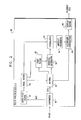
- Fig. 2 is a block diagram that schematically shows elements of ECG processor 28, in accordance with an embodiment of the present invention.
- ECG processor 28 may comprise a general-purpose computer, running any suitable operating system, with suitable input interfaces (not shown) for receiving ECG signals and software for performing the processing functions that are described hereinbelow. This software may be downloaded to the processor in electronic form, over a network, for example, or may be stored on tangible media, such as optical, magnetic, or electronic memory media.
- the ECG processor may comprise a special-purpose processing device, such as a programmable signal processor or a customized hardware control unit. Elements of ECG processor 28 may also be implemented as several separate processing devices.
- a raw ECG signal such as the aVR signal
- Converter 40 also acquires and provides a digital output of an average signal, such as the WCT signal. It is desirable that the sampling frequency ( f s ) of converter 40 be significantly higher than the line frequency ( f i ) to provide a high level of interference rejection. In certain embodiments, the sampling frequency is set at 8000 samples/sec.
- a band-pass filter 42 then processes the WCT signal to extract signal components in a range that includes the line interference component.
- a typical band-pass frequency range is set as 45-65 Hz (at -6 db).
- the band-pass filtered signal is then processed by a frequency meter 44, which determines the frequency of the line interference component. This determination may be made by measuring the time required for a set number of zero voltage crossings of the band-pass filtered signal. In one embodiment, the number of zero crossings counted is set to 120, i.e., 60 cycles. The calculation may also be performed by determining zero crossings of a second derivative of the band-pass signal.
- the average line interference frequency is updated on a continuous basis as each digital sample from the WCT is acquired.
- Samples, x n comprising the raw ECG signal acquired by converter 40, are buffered in a frame buffer 46.
- frame buffer 46 stores an ECG frame of exactly four cycles of the ECG signal or N 60, av /15 samples, as calculated by frequency meter 44.
- the frame length is set to four cycles as a compromise between minimizing processing time and providing sufficient information for the correlation procedure described hereinbelow.
- the samples are transmitted from frame buffer 46 to a comb filter 48.
- the comb filter may be implemented as a moving average of the raw signal, wherein the average is taken over a single cycle of the average line interference frequency, that is, over N 60, av /60 samples.
- the moving average is equal to a sum of N 60, av /60 terms, divided by the value of N 60, av /60.
- a residual generator 50 subtracts the moving average from the raw ECG signal to generate a residual signal s n .
- Residual signal s n comprises components of the raw ECG signal at frequencies at and above the average line interference frequency (as determined by frequency meter 44).
- the harmonic-bound residual signals s n m are input to a correlator 52, which determines the amplitude (A) and phase shift ( ⁇ ) of component interference signals in the harmonic-bound residual signals.
- the term s n 1 refers to the primary interference signal, also known as the first harmonic interference signal.
- a second harmonic interference signal corresponds to s n 2 , and so on.
- several harmonic-bound residual signals are calculated and input to correlator 52. Processing by all elements of ECG processor 28 is usually performed in real-time, such that a new value for amplitude and phase shift for each component interference signal is calculated as each ECG frame is acquired.
- correlator 52 may be understood as follows.
- the two correlations provide simultaneous equations for the calculation of amplitude and phase shift for interference signal s :
- a ⁇ cos ⁇ 2 ⁇ f q ⁇ 0 q ⁇ T s t ⁇ sin 2 ⁇ ⁇ ft d t
- a ⁇ sin ⁇ 2 ⁇ f q ⁇ 0 q ⁇ T s t ⁇ cos 2 ⁇ ⁇ ft d t .
- the above summations are performed over a frame of N 60, av /15 samples, which is equal to four frequency cycles of each respective component interference signal.
- the frame length may vary depending the allowable delay of the system. Using a larger frame allows more accurate determination of the amplitude and phase but increases the output delay because more samples need to be accumulated.
- an artifact processor 54 may modify the amplitude values, so as to limit the rate of change of these values with time.
- the limitation may be applied so as to prevent a sudden change between two sequential amplitude values or a sudden change between an amplitude value of the interference signal and a moving average of the amplitude.
- the value of A ( m ) is replaced by an immediately preceding value of A ( m ) .
- the limitation ensures that higher frequency components of the ECG signal, such as the peak of the QRS complex, will not affect interference estimation accuracy.
- the inventors have found that setting the threshold to 21% of the RMS amplitude A RMS m 2 gives good results, but other threshold values may similarly be used.
- the user of ECG monitor 24 may adjust the threshold value.
- artifact processor 54 calculates a difference between A ( m ) and an immediately preceding value of A ( m ) , retaining the immediately preceding value in place of the newer value if the difference between the two is greater than a threshold, such as 10% of the preceding value.
- the clean ECG signal may then be transferred to a display driver 60, which controls the display on screen 30.
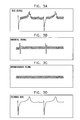
- Figs. 3A-3D are signal diagrams that schematically show signals at different stages of processing by ECG processor 28, in accordance with embodiments of the present invention.
- Fig. 3A shows a raw ECG signal, such as an aVR signal. A typical magnitude of this signal is up to several mV, before amplification. It can be seen that the signal includes a substantial interference component.
- Component interference signals induced on the raw ECG signal are isolated by the methods described hereinabove with respect to Fig. 2 .
- the residual signal produced by residual generator 50 is a precursor to subsequent generation of component interference signals.
- An example of the residual signal is shown in Fig. 3B .
- This signal includes not only the interference component, but also high-frequency components of the ECG signal.
- Correlator 52 and artifact processor 54 process the residual signal to generate interference signals correlated to each harmonic of the line interference frequency.
- Fig. 3C shows an example of an interference signal. Subtracting this component interference signal from the raw ECG signal gives a line-filtered signal, as shown in Fig. 3D .
- the principles of the present invention may also be applied to the removal of multiple types of interference from a range of biomedical signals, e.g., EEG, EMG, and various electrically and optically monitored signals. Furthermore, the principles of the present invention may likewise be applied in the context of other environments and industrial applications.
Landscapes
- Health & Medical Sciences (AREA)
- Life Sciences & Earth Sciences (AREA)
- Engineering & Computer Science (AREA)
- Molecular Biology (AREA)
- Animal Behavior & Ethology (AREA)
- Physics & Mathematics (AREA)
- Signal Processing (AREA)
- Biophysics (AREA)
- Pathology (AREA)
- Biomedical Technology (AREA)
- Heart & Thoracic Surgery (AREA)
- Medical Informatics (AREA)
- Computer Networks & Wireless Communication (AREA)
- Surgery (AREA)
- Cardiology (AREA)
- General Health & Medical Sciences (AREA)
- Public Health (AREA)
- Veterinary Medicine (AREA)
- Measurement And Recording Of Electrical Phenomena And Electrical Characteristics Of The Living Body (AREA)
- Radar Systems Or Details Thereof (AREA)
- Analysing Materials By The Use Of Radiation (AREA)
- Glass Compositions (AREA)
- Holo Graphy (AREA)
- Lasers (AREA)
Abstract
Description
- The present invention relates generally to monitoring biophysical parameters and in particular to the measurement of ECG signals.
- Instruments for measuring electrocardiogram (ECG) signals often detect electrical interference corresponding to a line, or mains, frequency. Line frequencies in most countries, though nominally set at 50 Hz or 60 Hz, may vary by several percent from these nominal values.
- Various methods for removing electrical interference from ECG signals are known in the art. Several of these methods make use of one or more low-pass or notch filters. For example,
U.S. Patent 4,887,609 , whose disclosure is incorporated herein by reference, describes a system for variable filtering of noise in ECG signals. The system has a plurality of low pass filters including one filter with a 3 dB point at approximately 50 Hz and a second low pass filter with a 3 dB point at approximately 5 Hz. -
U.S. Patent 6,807,443 , whose disclosure is incorporated herein by reference, describes a system for rejecting the line frequency component of an ECG signal by passing the signal through two serially linked notch filters.U.S. Patent 5,188,117 , whose disclosure is incorporated herein by reference, describes a system with a notch filter that may have either or both low-pass and high-pass coefficients for removing line frequency components from an ECG signal. The system also provides means for removing burst noise and for calculating a heart rate from the notch filter output. -
U.S. Patent 5,564,428 , whose disclosure is incorporated herein by reference, describes a system with several units for removing interference: a mean value unit to generate an average signal 0over several cardiac cycles, a subtracting unit to subtract the average signal from the input signal to generate a residual signal, a filter unit to provide a filtered signal from the residual signal, and an addition unit to add the filtered signal to the average signal. -
U.S. Patent 5,349,352 , whose disclosure is incorporated herein by reference, describes an analog-to-digital (A/D) converter that provides noise rejection by synchronizing a clock of the converter with a phase locked loop set to the line frequency. - Embodiments of the present invention provide methods and devices for removing electrical interference from a physiological signal. The embodiments described hereinbelow are particularly useful for filtering line interference induced in an electrocardiogram (ECG) signal. The principles of the present invention may also be applied in filtering other types of interference, such as interference induced by magnetic location systems and by magnetic resonance systems.
- In certain embodiments, a monitor digitally samples an ECG signal, referred to hereinbelow as a raw ECG signal. The monitor also samples an average signal, such as a signal acquired from a Wilson Central Terminal (WCT). The average signal is processed to determine an average frequency of primary interference.
- The raw ECG signal is then processed to remove signals at the average frequency of primary interference and at harmonics of that frequency. The filtered signal is subtracted from the raw signal to generate a residual signal, which includes interference signals at the average frequency and its harmonics. Amplitudes and phase shifts of these interference signals are estimated, artifacts are removed, and the resulting interference signals are subtracted from the raw ECG signal to generate a line-filtered ECG signal.
- There is therefore provided, in accordance with an embodiment of the present invention, a method for monitoring an electrocardiogram (ECG) signal of a subject, including:
- digitally sampling an average signal from at least a first ECG electrode attached to the subject;
- determining an average interference frequency of the average signal;
- digitally sampling and buffering a raw ECG signal from at least a second ECG electrode attached to the subject;
- filtering the raw ECG signal to generate a residual signal including frequency components at and above the average interference frequency;
- calculating, based on the residual signal, a first amplitude and a first phase shift of a primary interference signal at the average interference frequency and a second amplitude and a second phase shift of one or more harmonic interference signals at respective multiples of the average interference frequency; and
- digitally subtracting the primary interference signal and the one or more harmonic interference signals from the raw ECG signal so as to generate and output a clean ECG signal.
- Typically, the average signal includes a Wilson Central Terminal (WCT) signal.
- The method may include imposing a limit on a change in the first amplitude prior to subtracting the primary interference signal from the raw ECG signal. Imposing the limit may include setting the first amplitude equal to a preceding value of the first amplitude, responsively to determining that the first amplitude has changed by more than a predetermined factor relative to the preceding value. Imposing the limit may also include calculating a mean value of the residual signal and calculating a threshold based on the mean value. A limit may also be imposed on a change in the second amplitude prior to subtracting the one or more harmonic interference signals from the raw ECG signal.
- In some embodiments, filtering the raw ECG signal includes applying to the raw ECG signal a moving average filter, and generating the residual signal includes subtracting an output of the moving average filter from the raw ECG signal.
- Calculating the first amplitude and the first phase shift may include finding a correlation between the residual signal and a periodic function having a frequency equal to the average interference frequency.
- Similarly, calculating the second amplitude and the second phase shift may include finding a correlation between the residual signal and a periodic function having a frequency equal to a multiple of the average interference frequency.
- There is also provided, in accordance with an embodiment of the present invention, apparatus for monitoring an electrocardiogram (ECG) signal of a subject, including:
- a plurality of ECG electrodes, including at least a first and a second ECG electrode, attached to the subject; and
- a processor configured to sample an average signal from at least the first ECG electrode, to determine an average interference frequency of the average signal, to sample and buffer a raw ECG signal from at least the second ECG electrode, to filter the raw ECG signal to generate a residual signal including frequency components at and above the average interference frequency, to calculate, based on the residual signal, a first amplitude and a first phase shift of a primary interference signal at the average interference frequency and a second amplitude and a second phase shift of one or more harmonic interference signals at respective multiples of the average interference frequency, and to subtract the primary interference signal and the one or more harmonic interference signals from the raw ECG signal so as to generate and output a clean ECG signal.
- The present invention will be more fully understood from the following detailed description of the embodiments thereof, taken together with the drawings in which:
-
-
Fig. 1 is a schematic, pictorial illustration of a system for monitoring an ECG signal, in accordance with an embodiment of the present invention; -
Fig. 2 is a block diagram that schematically shows details of an ECG processor, in accordance with an embodiment of the present invention; and -
Figs. 3A-3D are signal diagrams that schematically show ECG signals at four stages of processing, in accordance with embodiments of the present invention. -
Fig. 1 is a schematic, pictorial illustration of asystem 20 for measuring and processing ECG signals of apatient 22, in accordance with an embodiment of the present invention. ECG signals are acquired by anECG monitor 24 fromelectrodes 26 placed on the body ofpatient 22.ECG monitor 24 comprises anECG processor 28 that processes the acquired signals and generates filtered signals that are presented on an output device, such as acomputer screen 30. Output devices may also include a printer as well as means for remote transmission and storage of the processed signals. - In addition to presenting filtered signals, the ECG monitor may also monitor other physiological parameters, such as ECG signal changes that may indicate heart failure. The ECG monitor may also transmit signals to external systems that provide for presentation, storage, or further signal processing. A user of
ECG monitor 24 may modify processing and presentation parameters through an input panel such as akeyboard 32. Presentation parameters may include options to view specific signals, as well as display options such as pan and zoom. Processing parameters may determine the type and extent of signal filtering, as well as settings for artifact thresholds, as described further hereinbelow. - Many configurations for placing
electrodes 26 on a patient's body are documented in the prior art. In a common configuration of ten electrodes, cited here by way of example, six ofelectrodes 26 are placed across the chest ofpatient 22 and four are placed at the extremities comprising the patient's left arm, right arm, left leg, and right leg. ECG signals are measured across various sets of the ten electrodes. Signals typically measured by the common ten-electrode configuration, are known as signals I, II, III, aVR, aVL, aVF, V1, V2, V3, V4, V5, and V6. - An average of three extremity voltages (by convention, voltages measured at the right arm, left arm, and left leg), is known as the Wilson Central Terminal (WCT). The WCT was initially described in Wilson NF, Johnston FE, Macleod AG, Barker PS, "Electrocardiograms that represent the potential variations of a single electrode," Am. Heart Journal, (1934;9:447-458), whose disclosure is incorporated herein by reference. The WCT is often used as a reference voltage for the V1-V6 signals and is therefore available for additional signal processing.
- Line interference that is induced in the body extremities is typically prevalent in the WCT.
ECG processor 28 exploits this aspect of the WCT to determine the line interference frequency, as described further hereinbelow. -
Fig. 2 is a block diagram that schematically shows elements ofECG processor 28, in accordance with an embodiment of the present invention.ECG processor 28 may comprise a general-purpose computer, running any suitable operating system, with suitable input interfaces (not shown) for receiving ECG signals and software for performing the processing functions that are described hereinbelow. This software may be downloaded to the processor in electronic form, over a network, for example, or may be stored on tangible media, such as optical, magnetic, or electronic memory media. Alternatively or additionally, the ECG processor may comprise a special-purpose processing device, such as a programmable signal processor or a customized hardware control unit. Elements ofECG processor 28 may also be implemented as several separate processing devices. - In an embodiment of the present invention, a raw ECG signal, such as the aVR signal, is acquired from
electrodes 26 and converted from an analog to a digital format by aconverter 40.Converter 40 also acquires and provides a digital output of an average signal, such as the WCT signal. It is desirable that the sampling frequency (fs ) ofconverter 40 be significantly higher than the line frequency (fi ) to provide a high level of interference rejection. In certain embodiments, the sampling frequency is set at 8000 samples/sec. - In some embodiments, a band-
pass filter 42 then processes the WCT signal to extract signal components in a range that includes the line interference component. A typical band-pass frequency range is set as 45-65 Hz (at -6 db). The band-pass filtered signal is then processed by afrequency meter 44, which determines the frequency of the line interference component. This determination may be made by measuring the time required for a set number of zero voltage crossings of the band-pass filtered signal. In one embodiment, the number of zero crossings counted is set to 120, i.e., 60 cycles. The calculation may also be performed by determining zero crossings of a second derivative of the band-pass signal. An average line interference frequency over the 60 cycles is calculated as fi = 60fs /N 60,av , wherein N 60,av is the number of zero crossings counted. In an embodiment of the present invention, the average line interference frequency is updated on a continuous basis as each digital sample from the WCT is acquired. - Samples, xn , comprising the raw ECG signal acquired by
converter 40, are buffered in aframe buffer 46. In some embodiments,frame buffer 46 stores an ECG frame of exactly four cycles of the ECG signal or N 60,av /15 samples, as calculated byfrequency meter 44. The frame length is set to four cycles as a compromise between minimizing processing time and providing sufficient information for the correlation procedure described hereinbelow. The samples are transmitted fromframe buffer 46 to acomb filter 48. The comb filter may be implemented as a moving average of the raw signal, wherein the average is taken over a single cycle of the average line interference frequency, that is, over N 60,av /60 samples. The moving average is equal to a sum of N 60,av /60 terms, divided by the value of N 60,av /60. - A
residual generator 50 subtracts the moving average from the raw ECG signal to generate a residual signal sn. In mathematic terms, the residual signal sn equals the raw signal, xn , minus the average of xn over a cycle (the average being the sum of xn over a cycle divided by N 60,av /60), as follows:
- Residual signal sn comprises components of the raw ECG signal at frequencies at and above the average line interference frequency (as determined by frequency meter 44). The processes implemented by
low pass filter 48 andresidual signal generator 50 may be repeated for harmonics of the line frequency, thereby generating, for each harmonic, m, a harmonic-bound residual signal,

- The harmonic-bound residual signals

correlator 52, which determines the amplitude (A) and phase shift (ϕ) of component interference signals in the harmonic-bound residual signals. The term

correlator 52. Processing by all elements ofECG processor 28 is usually performed in real-time, such that a new value for amplitude and phase shift for each component interference signal is calculated as each ECG frame is acquired. - The operation of
correlator 52 may be understood as follows. For analog signals, a correlation between a first signal x, having a component interference signal s of frequency f, and a second signal, comprising a cosine function with a frequency f, is given by:
Similarly, a correlation between x and a sine function of frequency f may be calculated as:
The two correlations provide simultaneous equations for the calculation of amplitude and phase shift for interference signal s:
and
- For discrete signals, the above equations for amplitude and phase shift are represented, for any given harmonic m, as follows:


wherein the integral over t in the analog equations is represented as a summation over n samples, and t is represented as n/fs. - The above summations are performed over a frame of N 60,av /15 samples, which is equal to four frequency cycles of each respective component interference signal. The frame length may vary depending the allowable delay of the system. Using a larger frame allows more accurate determination of the amplitude and phase but increases the output delay because more samples need to be accumulated.
- After the amplitudes and phase shifts of the interference signal harmonics are calculated, as above, an
artifact processor 54 may modify the amplitude values, so as to limit the rate of change of these values with time. The limitation may be applied so as to prevent a sudden change between two sequential amplitude values or a sudden change between an amplitude value of the interference signal and a moving average of the amplitude. - From the correlation equations (1) and (2), above, amplitudes for each harmonic are calculated according to the following equation:

To determine limits on values of amplitude,artifact processor 54 calculates normalized root-mean-square (RMS) amplitudes [A (m)]2 of residual signals

- In some embodiments, for a given value of [A (m)]2 that differs by more than a preset, empirically determined threshold based on the RMS amplitude


- In alternative embodiments,
artifact processor 54 calculates a difference between A (m) and an immediately preceding value of A (m), retaining the immediately preceding value in place of the newer value if the difference between the two is greater than a threshold, such as 10% of the preceding value. - After processing of the interference signal by
artifact processor 54, anaggregate subtraction module 58 sums all the harmonics of the interference signal and subtracts the sum from the raw ECG signal, to provide a clean, line-filtered ECG signal, yn :
wherein m = 1, 2, ... is the harmonic number of the interference signal. - The clean ECG signal, may then be transferred to a
display driver 60, which controls the display onscreen 30. -
Figs. 3A-3D are signal diagrams that schematically show signals at different stages of processing byECG processor 28, in accordance with embodiments of the present invention.Fig. 3A shows a raw ECG signal, such as an aVR signal. A typical magnitude of this signal is up to several mV, before amplification. It can be seen that the signal includes a substantial interference component. - Component interference signals induced on the raw ECG signal are isolated by the methods described hereinabove with respect to
Fig. 2 . The residual signal produced byresidual generator 50 is a precursor to subsequent generation of component interference signals. An example of the residual signal is shown inFig. 3B . This signal includes not only the interference component, but also high-frequency components of the ECG signal. -
Correlator 52 andartifact processor 54 process the residual signal to generate interference signals correlated to each harmonic of the line interference frequency.Fig. 3C shows an example of an interference signal. Subtracting this component interference signal from the raw ECG signal gives a line-filtered signal, as shown inFig. 3D . - Although the embodiments described above relate specifically to the removal of line interference from an ECG signal, the principles of the present invention may also be applied to the removal of multiple types of interference from a range of biomedical signals, e.g., EEG, EMG, and various electrically and optically monitored signals. Furthermore, the principles of the present invention may likewise be applied in the context of other environments and industrial applications.
- It will thus be appreciated that embodiments described above are cited by way of example, and that the present invention is not limited to what has been particularly shown and described hereinabove. Rather, the scope of the present invention includes both combinations and subcombinations of the various features described hereinabove, as well as variations and modifications thereof which would occur to persons skilled in the art upon reading the foregoing description and which are not disclosed in the prior art.
Claims (18)
- A method for monitoring an electrocardiogram (ECG) signal of a subject, comprising:digitally sampling an average signal from at least a first ECG electrode attached to the subject;determining an average interference frequency of the average signal;digitally sampling and buffering a raw ECG signal from at least a second ECG electrode attached to the subject;filtering the raw ECG signal to generate a residual signal comprising frequency components at and above the average interference frequency;calculating, based on the residual signal, a first amplitude and a first phase shift of a primary interference signal at the average interference frequency and a second amplitude and a second phase shift of one or more harmonic interference signals at respective multiples of the average interference frequency; anddigitally subtracting the primary interference signal and the one or more harmonic interference signals from the raw ECG signal so as to generate and output a clean ECG signal.
- The method according to claim 1, wherein the average signal comprises a Wilson Central Terminal (WCT) signal.
- The method according to claim 1, and comprising imposing a limit on a change in the first amplitude prior to subtracting the primary interference signal from the raw ECG signal.
- The method according to claim 3, wherein imposing the limit comprises setting the first amplitude equal to a preceding value of the first amplitude, responsively to determining that the first amplitude has changed by more than a predetermined factor relative to the preceding value.
- The method according to claim 3, wherein imposing the limit comprises calculating a mean value of the residual signal and calculating a threshold based on the mean value.
- The method according to claim 3, wherein the limit on the change in the first amplitude is a first limit and comprising imposing a second limit on a change in the second amplitude prior to subtracting the one or more harmonic interference signals from the raw ECG signal.
- The method according to claim 1, wherein filtering the raw ECG signal comprises applying to the raw ECG signal a moving average filter, and wherein generating the residual signal comprises subtracting an output of the moving average filter from the raw ECG signal.
- The method according to claim 1, wherein calculating the first amplitude and the first phase shift comprises finding a correlation between the residual signal and a periodic function having a frequency equal to the average interference frequency.
- The method according to claim 1, wherein calculating the second amplitude and the second phase shift comprises finding a correlation between the residual signal and a periodic function having a frequency equal to a multiple of the average interference frequency.
- Apparatus for monitoring an electrocardiogram (ECG) signal of a subject, comprising:a plurality of ECG electrodes, comprising at least a first and a second ECG electrode, attached to the subject; anda processor configured to sample an average signal from at least the first ECG electrode, to determine an average interference frequency of the average signal, to sample and buffer a raw ECG signal from at least the second ECG electrode, to filter the raw ECG signal to generate a residual signal comprising frequency components at and above the average interference frequency, to calculate, based on the residual signal, a first amplitude and a first phase shift of a primary interference signal at the average interference frequency and a second amplitude and a second phase shift of one or more harmonic interference signals at respective multiples of the average interference frequency, and to subtract the primary interference signal and the one or more harmonic interference signals from the raw ECG signal so as to generate and output a clean ECG signal.
- The apparatus according to claim 10, wherein the average signal comprises a Wilson Central Terminal (WCT) signal.
- The apparatus according to claim 10, wherein the processor is configured to impose a limit on a change in the first amplitude prior to subtracting the primary interference signal from the raw ECG signal.
- The apparatus according to claim 12, wherein the processor is configured to impose the limit by setting the first amplitude equal to a preceding value of the first amplitude, responsively to determining that the first amplitude has changed by more than a predetermined factor relative to the preceding value.
- The apparatus according to claim 12, wherein the processor is configured to impose the limit by calculating a mean value of the residual signal and by calculating a threshold based on the mean value.
- The apparatus according to claim 12, wherein the limit on the change in the first amplitude is a first limit and wherein the processor is configured to impose a second limit on a change in the second amplitude prior to subtracting the one or more harmonic interference signals from the raw ECG signal.
- The apparatus according to claim 10, wherein the processor is configured to filter the raw ECG signal by applying to the raw ECG signal a moving average filter, and wherein processor is configured to generate the residual signal by subtracting an output of the moving average filter from the raw ECG signal.
- The apparatus according to claim 10, wherein the processor is configured to calculate the first amplitude and the first phase shift by finding a correlation between the residual signal and a periodic function with a frequency equal to the average interference frequency.
- The apparatus according to claim 10, wherein the processor is configured to calculate the second amplitude and the second phase shift by finding a correlation between the residual signal and a periodic function with a frequency equal to a multiple of the average interference frequency.
Applications Claiming Priority (1)
| Application Number | Priority Date | Filing Date | Title |
|---|---|---|---|
| US11/743,195 US7894885B2 (en) | 2007-05-02 | 2007-05-02 | Coherent signal rejection in ECG |
Publications (2)
| Publication Number | Publication Date |
|---|---|
| EP1987767A1 true EP1987767A1 (en) | 2008-11-05 |
| EP1987767B1 EP1987767B1 (en) | 2010-08-11 |
Family
ID=39639095
Family Applications (1)
| Application Number | Title | Priority Date | Filing Date |
|---|---|---|---|
| EP08251600A Active EP1987767B1 (en) | 2007-05-02 | 2008-05-01 | Coherent signal rejection in ECG |
Country Status (13)
| Country | Link |
|---|---|
| US (1) | US7894885B2 (en) |
| EP (1) | EP1987767B1 (en) |
| JP (1) | JP5191791B2 (en) |
| KR (1) | KR20080097934A (en) |
| CN (1) | CN101297754B (en) |
| AT (1) | ATE476913T1 (en) |
| AU (1) | AU2008201890B2 (en) |
| BR (1) | BRPI0801529A2 (en) |
| CA (1) | CA2630019C (en) |
| DE (1) | DE602008002089D1 (en) |
| ES (1) | ES2348000T3 (en) |
| IL (1) | IL191050A0 (en) |
| MX (1) | MX2008005809A (en) |
Cited By (3)
| Publication number | Priority date | Publication date | Assignee | Title |
|---|---|---|---|---|
| EP3391814A1 (en) * | 2017-04-19 | 2018-10-24 | Siemens Healthcare GmbH | Reference methodology for ecg vector reconstruction |
| EP3679860A4 (en) * | 2017-09-08 | 2021-05-05 | Maisonburg (Shenzhen) Technology Development Co., Ltd. | WORKING FREQUENCY INTERFERENCE SIGNAL CONTROL PROCESS AND FILTRATION SYSTEM |
| EP4226849A3 (en) * | 2022-02-14 | 2023-10-25 | Biosense Webster (Israel) Ltd. | Filtering power line noises from analog electrophysiological signals in real-time |
Families Citing this family (102)
| Publication number | Priority date | Publication date | Assignee | Title |
|---|---|---|---|---|
| US9572497B2 (en) | 2008-07-25 | 2017-02-21 | Helmholtz Zentrum Munchen Deutsches Forschungszentrum Fur Gesundheit Und Umwelt (Gmbh) | Quantitative multi-spectral opto-acoustic tomography (MSOT) of tissue biomarkers |
| JP5566456B2 (en) | 2009-06-29 | 2014-08-06 | ヘルムホルツ・ツェントルム・ミュンヒェン・ドイチェス・フォルシュンクスツェントルム・フューア・ゲズントハイト・ウント・ウムベルト(ゲーエムベーハー) | Imaging apparatus and imaging method, computer program, and computer readable storage medium for thermoacoustic imaging of a subject |
| EP2459987A1 (en) | 2009-07-27 | 2012-06-06 | Helmholtz Zentrum München Deutsches Forschungszentrum für Gesundheit und Umwelt (GmbH) | Imaging device and method for optoacoustic imaging of small animals |
| WO2011017778A1 (en) * | 2009-08-14 | 2011-02-17 | David Burton | Anaesthesia and consciousness depth monitoring system |
| US8761867B2 (en) * | 2009-09-16 | 2014-06-24 | General Electric Company | Method and system for reducing power line interferences in an ECG signal |
| KR101674580B1 (en) | 2010-03-26 | 2016-11-09 | 삼성전자주식회사 | Apparatus and method for measuring biological signal |
| KR101736978B1 (en) | 2010-06-10 | 2017-05-17 | 삼성전자주식회사 | Apparatus and method for measuring biological signal |
| KR101800706B1 (en) | 2011-03-08 | 2017-11-24 | 삼성전자 주식회사 | Apparatus, unit measurer and method for measuring biological signal without noise |
| KR101815942B1 (en) * | 2011-12-02 | 2018-01-09 | 삼성전자주식회사 | A method and an apparatus for envelope detection |
| KR101367596B1 (en) * | 2012-05-15 | 2014-02-26 | 주식회사 씨유메디칼시스템 | Automated external defibrillator including motion artifact measurement and deleting facility |
| US8827993B2 (en) | 2012-06-13 | 2014-09-09 | Biosense Webster (Israel) Ltd. | Gated sampling of electrocardiogram signals during ablation waveform zero-crossing |
| US9198588B2 (en) | 2012-10-31 | 2015-12-01 | Welch Allyn, Inc. | Frequency-adaptive notch filter |
| EP2742854B1 (en) | 2012-12-11 | 2021-03-10 | iThera Medical GmbH | Handheld device and method for tomographic optoacoustic imaging of an object |
| EP2754388B1 (en) | 2013-01-15 | 2020-09-09 | Helmholtz Zentrum München Deutsches Forschungszentrum für Gesundheit und Umwelt GmbH | System and method for quality-enhanced high-rate optoacoustic imaging of an object |
| JP6015479B2 (en) * | 2013-02-08 | 2016-10-26 | トヨタ自動車株式会社 | Biological information acquisition apparatus and biological information acquisition method |
| US20140278171A1 (en) * | 2013-03-15 | 2014-09-18 | Robert James Kahlke | Frequency Adaptive Line Voltage Filters |
| US9585621B2 (en) | 2013-03-25 | 2017-03-07 | Iliya Mitov | Technique for real-time removal of power line interference in ECG |
| US9414787B2 (en) | 2013-11-21 | 2016-08-16 | Welch Allyn, Inc. | Navigation features for electrocardiograph device user interface |
| KR102169378B1 (en) | 2014-02-18 | 2020-10-23 | 삼성전자주식회사 | An electrocardiogram (ecg) sensor and a method of operating the same |
| WO2015171804A1 (en) * | 2014-05-08 | 2015-11-12 | Draeger Medical Systems, Inc. | Detecting artifacts in a signal |
| US9538930B2 (en) * | 2014-06-05 | 2017-01-10 | Guangren CHEN | Linear multi-domain electrocardiogram |
| ES2713231T3 (en) | 2015-02-06 | 2019-05-20 | Cardiac Pacemakers Inc | Systems for the safe supply of electrical stimulation therapy |
| WO2016130477A2 (en) | 2015-02-09 | 2016-08-18 | Cardiac Pacemakers, Inc. | Implantable medical device with radiopaque id tag |
| US11285326B2 (en) | 2015-03-04 | 2022-03-29 | Cardiac Pacemakers, Inc. | Systems and methods for treating cardiac arrhythmias |
| WO2017031221A1 (en) | 2015-08-20 | 2017-02-23 | Cardiac Pacemakers, Inc. | Systems and methods for communication between medical devices |
| CN108136187B (en) | 2015-08-20 | 2021-06-29 | 心脏起搏器股份公司 | System and method for communication between medical devices |
| US10226631B2 (en) | 2015-08-28 | 2019-03-12 | Cardiac Pacemakers, Inc. | Systems and methods for infarct detection |
| EP3341076B1 (en) | 2015-08-28 | 2022-05-11 | Cardiac Pacemakers, Inc. | Systems and methods for behaviorally responsive signal detection and therapy delivery |
| WO2017040115A1 (en) | 2015-08-28 | 2017-03-09 | Cardiac Pacemakers, Inc. | System for detecting tamponade |
| WO2017062806A1 (en) | 2015-10-08 | 2017-04-13 | Cardiac Pacemakers, Inc. | Devices and methods for adjusting pacing rates in an implantable medical device |
| EP3389775B1 (en) | 2015-12-17 | 2019-09-25 | Cardiac Pacemakers, Inc. | Conducted communication in a medical device system |
| US10905886B2 (en) | 2015-12-28 | 2021-02-02 | Cardiac Pacemakers, Inc. | Implantable medical device for deployment across the atrioventricular septum |
| WO2017127548A1 (en) | 2016-01-19 | 2017-07-27 | Cardiac Pacemakers, Inc. | Devices for wirelessly recharging a rechargeable battery of an implantable medical device |
| EP3411113B1 (en) | 2016-02-04 | 2019-11-27 | Cardiac Pacemakers, Inc. | Delivery system with force sensor for leadless cardiac device |
| WO2017173275A1 (en) | 2016-03-31 | 2017-10-05 | Cardiac Pacemakers, Inc. | Implantable medical device with rechargeable battery |
| US10328272B2 (en) | 2016-05-10 | 2019-06-25 | Cardiac Pacemakers, Inc. | Retrievability for implantable medical devices |
| US10668294B2 (en) | 2016-05-10 | 2020-06-02 | Cardiac Pacemakers, Inc. | Leadless cardiac pacemaker configured for over the wire delivery |
| US10362950B2 (en) | 2016-06-24 | 2019-07-30 | Analytics For Life Inc. | Non-invasive method and system for measuring myocardial ischemia, stenosis identification, localization and fractional flow reserve estimation |
| CN109414582B (en) | 2016-06-27 | 2022-10-28 | 心脏起搏器股份公司 | Cardiac therapy system for resynchronization pacing management using subcutaneous sensing of P-waves |
| US11207527B2 (en) | 2016-07-06 | 2021-12-28 | Cardiac Pacemakers, Inc. | Method and system for determining an atrial contraction timing fiducial in a leadless cardiac pacemaker system |
| WO2018009392A1 (en) | 2016-07-07 | 2018-01-11 | Cardiac Pacemakers, Inc. | Leadless pacemaker using pressure measurements for pacing capture verification |
| EP3487579B1 (en) | 2016-07-20 | 2020-11-25 | Cardiac Pacemakers, Inc. | System for utilizing an atrial contraction timing fiducial in a leadless cardiac pacemaker system |
| EP3500342B1 (en) | 2016-08-19 | 2020-05-13 | Cardiac Pacemakers, Inc. | Trans-septal implantable medical device |
| WO2018039335A1 (en) | 2016-08-24 | 2018-03-01 | Cardiac Pacemakers, Inc. | Integrated multi-device cardiac resynchronization therapy using p-wave to pace timing |
| US10870008B2 (en) | 2016-08-24 | 2020-12-22 | Cardiac Pacemakers, Inc. | Cardiac resynchronization using fusion promotion for timing management |
| WO2018057318A1 (en) | 2016-09-21 | 2018-03-29 | Cardiac Pacemakers, Inc. | Leadless stimulation device with a housing that houses internal components of the leadless stimulation device and functions as the battery case and a terminal of an internal battery |
| WO2018057626A1 (en) | 2016-09-21 | 2018-03-29 | Cardiac Pacemakers, Inc. | Implantable cardiac monitor |
| US10292596B2 (en) | 2016-09-21 | 2019-05-21 | Analytics For Life Inc. | Method and system for visualization of heart tissue at risk |
| US10758737B2 (en) | 2016-09-21 | 2020-09-01 | Cardiac Pacemakers, Inc. | Using sensor data from an intracardially implanted medical device to influence operation of an extracardially implantable cardioverter |
| EP3532161B1 (en) | 2016-10-27 | 2023-08-30 | Cardiac Pacemakers, Inc. | Implantable medical device with pressure sensor |
| EP3532159B1 (en) | 2016-10-27 | 2021-12-22 | Cardiac Pacemakers, Inc. | Implantable medical device delivery system with integrated sensor |
| US10463305B2 (en) | 2016-10-27 | 2019-11-05 | Cardiac Pacemakers, Inc. | Multi-device cardiac resynchronization therapy with timing enhancements |
| US10561330B2 (en) | 2016-10-27 | 2020-02-18 | Cardiac Pacemakers, Inc. | Implantable medical device having a sense channel with performance adjustment |
| US10413733B2 (en) | 2016-10-27 | 2019-09-17 | Cardiac Pacemakers, Inc. | Implantable medical device with gyroscope |
| EP3532160B1 (en) | 2016-10-27 | 2023-01-25 | Cardiac Pacemakers, Inc. | Separate device in managing the pace pulse energy of a cardiac pacemaker |
| WO2018081721A1 (en) | 2016-10-31 | 2018-05-03 | Cardiac Pacemakers, Inc | Systems for activity level pacing |
| US10617874B2 (en) | 2016-10-31 | 2020-04-14 | Cardiac Pacemakers, Inc. | Systems and methods for activity level pacing |
| US10583301B2 (en) | 2016-11-08 | 2020-03-10 | Cardiac Pacemakers, Inc. | Implantable medical device for atrial deployment |
| EP3538213B1 (en) | 2016-11-09 | 2023-04-12 | Cardiac Pacemakers, Inc. | Systems and devices for setting cardiac pacing pulse parameters for a cardiac pacing device |
| EP3541473B1 (en) | 2016-11-21 | 2020-11-11 | Cardiac Pacemakers, Inc. | Leadless cardiac pacemaker with multimode communication |
| US11147979B2 (en) | 2016-11-21 | 2021-10-19 | Cardiac Pacemakers, Inc. | Implantable medical device with a magnetically permeable housing and an inductive coil disposed about the housing |
| US10881869B2 (en) | 2016-11-21 | 2021-01-05 | Cardiac Pacemakers, Inc. | Wireless re-charge of an implantable medical device |
| US10894163B2 (en) | 2016-11-21 | 2021-01-19 | Cardiac Pacemakers, Inc. | LCP based predictive timing for cardiac resynchronization |
| US10639486B2 (en) | 2016-11-21 | 2020-05-05 | Cardiac Pacemakers, Inc. | Implantable medical device with recharge coil |
| US11207532B2 (en) | 2017-01-04 | 2021-12-28 | Cardiac Pacemakers, Inc. | Dynamic sensing updates using postural input in a multiple device cardiac rhythm management system |
| WO2018140623A1 (en) | 2017-01-26 | 2018-08-02 | Cardiac Pacemakers, Inc. | Leadless device with overmolded components |
| US10835753B2 (en) | 2017-01-26 | 2020-11-17 | Cardiac Pacemakers, Inc. | Intra-body device communication with redundant message transmission |
| WO2018140797A1 (en) | 2017-01-26 | 2018-08-02 | Cardiac Pacemakers, Inc. | Leadless implantable device with detachable fixation |
| EP3381354A1 (en) * | 2017-03-31 | 2018-10-03 | Koninklijke Philips N.V. | Methods and system for processing an emg signal |
| US10905872B2 (en) | 2017-04-03 | 2021-02-02 | Cardiac Pacemakers, Inc. | Implantable medical device with a movable electrode biased toward an extended position |
| AU2018248361B2 (en) | 2017-04-03 | 2020-08-27 | Cardiac Pacemakers, Inc. | Cardiac pacemaker with pacing pulse energy adjustment based on sensed heart rate |
| US10321837B2 (en) * | 2017-04-28 | 2019-06-18 | Biosense Webster (Israel) Ltd. | ECG machine including filter for feature detection |
| WO2019036568A1 (en) | 2017-08-18 | 2019-02-21 | Cardiac Pacemakers, Inc. | Implantable medical device with a flux concentrator and a receiving coil disposed about the flux concentrator |
| WO2019036600A1 (en) | 2017-08-18 | 2019-02-21 | Cardiac Pacemakers, Inc. | Implantable medical device with pressure sensor |
| JP6938778B2 (en) | 2017-09-20 | 2021-09-22 | カーディアック ペースメイカーズ, インコーポレイテッド | Implantable medical device with multiple modes of operation |
| US11185703B2 (en) | 2017-11-07 | 2021-11-30 | Cardiac Pacemakers, Inc. | Leadless cardiac pacemaker for bundle of his pacing |
| US11813463B2 (en) | 2017-12-01 | 2023-11-14 | Cardiac Pacemakers, Inc. | Leadless cardiac pacemaker with reversionary behavior |
| EP3717063B1 (en) | 2017-12-01 | 2023-12-27 | Cardiac Pacemakers, Inc. | Systems for detecting atrial contraction timing fiducials and determining a cardiac interval from a ventricularly implanted leadless cardiac pacemaker |
| CN111432874A (en) | 2017-12-01 | 2020-07-17 | 心脏起搏器股份公司 | Method and system for detecting atrial contraction timing reference within search window from a ventricular implanted leadless cardiac pacemaker |
| CN111417433B (en) | 2017-12-01 | 2024-04-30 | 心脏起搏器股份公司 | Method and system for detecting atrial contraction timing reference during ventricular filling from a ventricularly implanted leadless cardiac pacemaker |
| US11529523B2 (en) | 2018-01-04 | 2022-12-20 | Cardiac Pacemakers, Inc. | Handheld bridge device for providing a communication bridge between an implanted medical device and a smartphone |
| CN111556773A (en) | 2018-01-04 | 2020-08-18 | 心脏起搏器股份公司 | Dual chamber pacing without beat-to-beat communication |
| CN111886046B (en) | 2018-03-23 | 2025-05-27 | 美敦力公司 | AV-synchronized VFA cardiac therapy |
| JP2021518192A (en) | 2018-03-23 | 2021-08-02 | メドトロニック,インコーポレイテッド | VfA cardiac resynchronization therapy |
| CN111936046B (en) | 2018-03-23 | 2024-06-28 | 美敦力公司 | VFA Cardiac Therapy for Tachycardia |
| US11235161B2 (en) | 2018-09-26 | 2022-02-01 | Medtronic, Inc. | Capture in ventricle-from-atrium cardiac therapy |
| US11951313B2 (en) | 2018-11-17 | 2024-04-09 | Medtronic, Inc. | VFA delivery systems and methods |
| US12296177B2 (en) | 2018-12-21 | 2025-05-13 | Medtronic, Inc. | Delivery systems and methods for left ventricular pacing |
| US11679265B2 (en) | 2019-02-14 | 2023-06-20 | Medtronic, Inc. | Lead-in-lead systems and methods for cardiac therapy |
| US11697025B2 (en) | 2019-03-29 | 2023-07-11 | Medtronic, Inc. | Cardiac conduction system capture |
| US11213676B2 (en) | 2019-04-01 | 2022-01-04 | Medtronic, Inc. | Delivery systems for VfA cardiac therapy |
| US11712188B2 (en) | 2019-05-07 | 2023-08-01 | Medtronic, Inc. | Posterior left bundle branch engagement |
| US11305127B2 (en) | 2019-08-26 | 2022-04-19 | Medtronic Inc. | VfA delivery and implant region detection |
| US11813466B2 (en) | 2020-01-27 | 2023-11-14 | Medtronic, Inc. | Atrioventricular nodal stimulation |
| US12543992B2 (en) | 2020-03-30 | 2026-02-10 | Medtronic, Inc. | Pacing efficacy determination using a representative morphology of external cardiac signals |
| US11911168B2 (en) | 2020-04-03 | 2024-02-27 | Medtronic, Inc. | Cardiac conduction system therapy benefit determination |
| US12605103B2 (en) | 2020-05-21 | 2026-04-21 | Medtronic, Inc. | QRS detection and bracketing |
| US12465770B2 (en) | 2020-07-31 | 2025-11-11 | Medtronic, Inc. | Coronary sinus conduction system pacing and delivery |
| US11813464B2 (en) | 2020-07-31 | 2023-11-14 | Medtronic, Inc. | Cardiac conduction system evaluation |
| CN112401906B (en) * | 2020-11-10 | 2021-12-14 | 河北省科学院应用数学研究所 | Automatic electroencephalogram artifact removing method based on amplitude |
| CN115219968B (en) * | 2021-04-14 | 2025-06-27 | 西门子(深圳)磁共振有限公司 | Method, device, system and storage medium for reducing radio frequency interference |
| EP4740862A1 (en) | 2024-11-12 | 2026-05-13 | Universidad de Granada | An improved procedure for reduction of quasi-periodic interferences |
Citations (8)
| Publication number | Priority date | Publication date | Assignee | Title |
|---|---|---|---|---|
| US4211237A (en) * | 1977-04-14 | 1980-07-08 | Biotronik Mess- Und Therapiegerate Gmbh & Co. | Method and apparatus for identifying recurring signal patterns |
| US4887609A (en) | 1987-05-13 | 1989-12-19 | The Methodist Hospital System | Apparatus and method for filtering electrocardiograph signals |
| US5188117A (en) | 1991-10-25 | 1993-02-23 | Telectronics Pacing Systems, Inc. | Notch filter noise rejection system in a cardiac control device |
| US5349352A (en) | 1992-12-21 | 1994-09-20 | Harris Corporation | Analog-to-digital converter having high AC line noise rejection and insensitive to AC line frequency variations |
| US5564428A (en) | 1993-07-16 | 1996-10-15 | Siemens-Elema Ab | Method and apparatus for enhancing the signal-to-noise ratio of ECG signals |
| US6351664B1 (en) * | 1999-11-12 | 2002-02-26 | Ge Medical Systems Information Technologies, Inc. | Method of removing signal interference from sampled data and apparatus for effecting the same |
| US6807443B2 (en) | 2001-05-01 | 2004-10-19 | Cheetah Medical Inc. | High-resolution medical monitoring apparatus particularly useful for electrocardiographs |
| US20070083128A1 (en) * | 2005-10-10 | 2007-04-12 | Wayne Cote | Adaptive real-time line noise suppression for electrical or magnetic physiological signals |
Family Cites Families (6)
| Publication number | Priority date | Publication date | Assignee | Title |
|---|---|---|---|---|
| US635664A (en) * | 1899-01-28 | 1899-10-24 | Benjamin H Coursey | Cycle brake and motor. |
| US4537200A (en) * | 1983-07-07 | 1985-08-27 | The Board Of Trustees Of The Leland Stanford Junior University | ECG enhancement by adaptive cancellation of electrosurgical interference |
| US4579125A (en) * | 1984-01-23 | 1986-04-01 | Cns, Inc. | Real-time EEG spectral analyzer |
| CN1070043C (en) * | 1995-06-27 | 2001-08-29 | 深圳安科高技术有限公司 | Method and circuit of eliminating radio intereference in electrocardiac channel |
| US5999845A (en) * | 1997-05-21 | 1999-12-07 | Quinton Instrument Company | Muscle artifact noise detector for ECG signals |
| SE9703948D0 (en) * | 1997-10-29 | 1997-10-29 | Siemens Elema Ab | Electrocardiogram signal processing apparatus |
-
2007
- 2007-05-02 US US11/743,195 patent/US7894885B2/en active Active
-
2008
- 2008-04-25 CA CA2630019A patent/CA2630019C/en not_active Expired - Fee Related
- 2008-04-27 IL IL191050A patent/IL191050A0/en active IP Right Grant
- 2008-04-30 KR KR1020080040527A patent/KR20080097934A/en not_active Withdrawn
- 2008-04-30 AU AU2008201890A patent/AU2008201890B2/en not_active Ceased
- 2008-04-30 MX MX2008005809A patent/MX2008005809A/en unknown
- 2008-04-30 CN CN2008101277196A patent/CN101297754B/en active Active
- 2008-05-01 DE DE602008002089T patent/DE602008002089D1/en active Active
- 2008-05-01 JP JP2008119556A patent/JP5191791B2/en active Active
- 2008-05-01 ES ES08251600T patent/ES2348000T3/en active Active
- 2008-05-01 AT AT08251600T patent/ATE476913T1/en not_active IP Right Cessation
- 2008-05-01 EP EP08251600A patent/EP1987767B1/en active Active
- 2008-05-02 BR BRPI0801529-5A patent/BRPI0801529A2/en not_active IP Right Cessation
Patent Citations (8)
| Publication number | Priority date | Publication date | Assignee | Title |
|---|---|---|---|---|
| US4211237A (en) * | 1977-04-14 | 1980-07-08 | Biotronik Mess- Und Therapiegerate Gmbh & Co. | Method and apparatus for identifying recurring signal patterns |
| US4887609A (en) | 1987-05-13 | 1989-12-19 | The Methodist Hospital System | Apparatus and method for filtering electrocardiograph signals |
| US5188117A (en) | 1991-10-25 | 1993-02-23 | Telectronics Pacing Systems, Inc. | Notch filter noise rejection system in a cardiac control device |
| US5349352A (en) | 1992-12-21 | 1994-09-20 | Harris Corporation | Analog-to-digital converter having high AC line noise rejection and insensitive to AC line frequency variations |
| US5564428A (en) | 1993-07-16 | 1996-10-15 | Siemens-Elema Ab | Method and apparatus for enhancing the signal-to-noise ratio of ECG signals |
| US6351664B1 (en) * | 1999-11-12 | 2002-02-26 | Ge Medical Systems Information Technologies, Inc. | Method of removing signal interference from sampled data and apparatus for effecting the same |
| US6807443B2 (en) | 2001-05-01 | 2004-10-19 | Cheetah Medical Inc. | High-resolution medical monitoring apparatus particularly useful for electrocardiographs |
| US20070083128A1 (en) * | 2005-10-10 | 2007-04-12 | Wayne Cote | Adaptive real-time line noise suppression for electrical or magnetic physiological signals |
Cited By (5)
| Publication number | Priority date | Publication date | Assignee | Title |
|---|---|---|---|---|
| EP3391814A1 (en) * | 2017-04-19 | 2018-10-24 | Siemens Healthcare GmbH | Reference methodology for ecg vector reconstruction |
| EP3679860A4 (en) * | 2017-09-08 | 2021-05-05 | Maisonburg (Shenzhen) Technology Development Co., Ltd. | WORKING FREQUENCY INTERFERENCE SIGNAL CONTROL PROCESS AND FILTRATION SYSTEM |
| US11540763B2 (en) | 2017-09-08 | 2023-01-03 | Maisonburg (Shenzhen) Technology Development Co., Ltd. | Control method and system for filtering power line interferences |
| EP4226849A3 (en) * | 2022-02-14 | 2023-10-25 | Biosense Webster (Israel) Ltd. | Filtering power line noises from analog electrophysiological signals in real-time |
| US12465261B2 (en) | 2022-02-14 | 2025-11-11 | Biosense Webster (Israel) Ltd. | Filtering power line noises from analog electrophysiological signals in real-time |
Also Published As
| Publication number | Publication date |
|---|---|
| HK1125810A1 (en) | 2009-08-21 |
| US7894885B2 (en) | 2011-02-22 |
| AU2008201890B2 (en) | 2012-10-25 |
| MX2008005809A (en) | 2009-03-02 |
| JP2008284352A (en) | 2008-11-27 |
| JP5191791B2 (en) | 2013-05-08 |
| AU2008201890A1 (en) | 2008-11-20 |
| KR20080097934A (en) | 2008-11-06 |
| CA2630019A1 (en) | 2008-11-02 |
| BRPI0801529A2 (en) | 2008-12-16 |
| CA2630019C (en) | 2013-10-08 |
| ES2348000T3 (en) | 2010-11-26 |
| IL191050A0 (en) | 2008-12-29 |
| US20080275353A1 (en) | 2008-11-06 |
| CN101297754A (en) | 2008-11-05 |
| EP1987767B1 (en) | 2010-08-11 |
| ATE476913T1 (en) | 2010-08-15 |
| CN101297754B (en) | 2012-08-08 |
| DE602008002089D1 (en) | 2010-09-23 |
Similar Documents
| Publication | Publication Date | Title |
|---|---|---|
| EP1987767B1 (en) | Coherent signal rejection in ECG | |
| Luo et al. | A review of electrocardiogram filtering | |
| EP0647426B1 (en) | A dynamic filter for real-time artifact removal from waveforms | |
| TWI481196B (en) | Bioelectric signal sensing instrument and its baseline drift removal device | |
| US20060020218A1 (en) | Method and apparatus for continuous electrode impedance monitoring | |
| WO2005101229A1 (en) | Nonlinear method and apparatus for electrocardiogram pacemaker signal filtering | |
| EP3065821B1 (en) | Variable bandwidth ecg high pass filter | |
| CN114190917A (en) | A method and system for monitoring vital signs based on millimeter wave radar | |
| EP2753235A1 (en) | Electrocardiogram baseline removal | |
| Sohal et al. | Comparative analysis of heart rate variability parameters for arrhythmia and atrial fibrillation using ANOVA | |
| JPWO2018155384A1 (en) | Detection device | |
| KR101992763B1 (en) | Device and method of abnormal electrocardiographic signals information output | |
| CN110575159A (en) | Signal baseline resetting method and device and monitor | |
| HK1125810B (en) | Coherent signal rejection in ecg | |
| EP1215996B1 (en) | Analytical signal method for analysis of t-wave alternans | |
| AU2004215917B2 (en) | Method and apparatus for continuous electrode impedance monitoring | |
| Azucena et al. | Design and implementation of a simple portable biomedical electronic device to diagnose cardiac arrhythmias | |
| Maniam et al. | Biosensor Interface Controller for Chronic Kidney Disease Monitoring Using Internet of Things (IoT) | |
| Hidayat et al. | An approach of adaptive notch filtering design for electrocardiogram noise cancellation | |
| KR20190035058A (en) | Device and method of minnesota code output | |
| KR101006933B1 (en) | Signal processing device and method for heartbeat pulse signal | |
| KR101587989B1 (en) | Method of evaluating a value for heart regularity by bioacoustic and electronic stethoscope | |
| Singh | MATLAB based ECG signal noise removal and its analysis | |
| Borik et al. | A piezoelectric Foil Sensor used for Arterial Pulse Measurement | |
| JP2020048712A (en) | Pulse discrimination device and electrocardiogram analyzer |
Legal Events
| Date | Code | Title | Description |
|---|---|---|---|
| PUAI | Public reference made under article 153(3) epc to a published international application that has entered the european phase |
Free format text: ORIGINAL CODE: 0009012 |
|
| AK | Designated contracting states |
Kind code of ref document: A1 Designated state(s): AT BE BG CH CY CZ DE DK EE ES FI FR GB GR HR HU IE IS IT LI LT LU LV MC MT NL NO PL PT RO SE SI SK TR |
|
| AX | Request for extension of the european patent |
Extension state: AL BA MK RS |
|
| 17P | Request for examination filed |
Effective date: 20090424 |
|
| 17Q | First examination report despatched |
Effective date: 20090602 |
|
| AKX | Designation fees paid |
Designated state(s): AT BE BG CH CY CZ DE DK EE ES FI FR GB GR HR HU IE IS IT LI LT LU LV MC MT NL NO PL PT RO SE SI SK TR |
|
| REG | Reference to a national code |
Ref country code: HK Ref legal event code: DE Ref document number: 1125810 Country of ref document: HK |
|
| GRAP | Despatch of communication of intention to grant a patent |
Free format text: ORIGINAL CODE: EPIDOSNIGR1 |
|
| GRAS | Grant fee paid |
Free format text: ORIGINAL CODE: EPIDOSNIGR3 |
|
| GRAA | (expected) grant |
Free format text: ORIGINAL CODE: 0009210 |
|
| AK | Designated contracting states |
Kind code of ref document: B1 Designated state(s): AT BE BG CH CY CZ DE DK EE ES FI FR GB GR HR HU IE IS IT LI LT LU LV MC MT NL NO PL PT RO SE SI SK TR |
|
| REG | Reference to a national code |
Ref country code: GB Ref legal event code: FG4D |
|
| REG | Reference to a national code |
Ref country code: CH Ref legal event code: EP |
|
| REG | Reference to a national code |
Ref country code: IE Ref legal event code: FG4D |
|
| REF | Corresponds to: |
Ref document number: 602008002089 Country of ref document: DE Date of ref document: 20100923 Kind code of ref document: P |
|
| REG | Reference to a national code |
Ref country code: NL Ref legal event code: T3 |
|
| LTIE | Lt: invalidation of european patent or patent extension |
Effective date: 20100811 |
|
| PG25 | Lapsed in a contracting state [announced via postgrant information from national office to epo] |
Ref country code: NO Free format text: LAPSE BECAUSE OF FAILURE TO SUBMIT A TRANSLATION OF THE DESCRIPTION OR TO PAY THE FEE WITHIN THE PRESCRIBED TIME-LIMIT Effective date: 20101111 Ref country code: LT Free format text: LAPSE BECAUSE OF FAILURE TO SUBMIT A TRANSLATION OF THE DESCRIPTION OR TO PAY THE FEE WITHIN THE PRESCRIBED TIME-LIMIT Effective date: 20100811 Ref country code: FI Free format text: LAPSE BECAUSE OF FAILURE TO SUBMIT A TRANSLATION OF THE DESCRIPTION OR TO PAY THE FEE WITHIN THE PRESCRIBED TIME-LIMIT Effective date: 20100811 Ref country code: AT Free format text: LAPSE BECAUSE OF FAILURE TO SUBMIT A TRANSLATION OF THE DESCRIPTION OR TO PAY THE FEE WITHIN THE PRESCRIBED TIME-LIMIT Effective date: 20100811 |
|
| REG | Reference to a national code |
Ref country code: HK Ref legal event code: GR Ref document number: 1125810 Country of ref document: HK |
|
| PG25 | Lapsed in a contracting state [announced via postgrant information from national office to epo] |
Ref country code: PL Free format text: LAPSE BECAUSE OF FAILURE TO SUBMIT A TRANSLATION OF THE DESCRIPTION OR TO PAY THE FEE WITHIN THE PRESCRIBED TIME-LIMIT Effective date: 20100811 Ref country code: IS Free format text: LAPSE BECAUSE OF FAILURE TO SUBMIT A TRANSLATION OF THE DESCRIPTION OR TO PAY THE FEE WITHIN THE PRESCRIBED TIME-LIMIT Effective date: 20101211 Ref country code: HR Free format text: LAPSE BECAUSE OF FAILURE TO SUBMIT A TRANSLATION OF THE DESCRIPTION OR TO PAY THE FEE WITHIN THE PRESCRIBED TIME-LIMIT Effective date: 20100811 Ref country code: CY Free format text: LAPSE BECAUSE OF FAILURE TO SUBMIT A TRANSLATION OF THE DESCRIPTION OR TO PAY THE FEE WITHIN THE PRESCRIBED TIME-LIMIT Effective date: 20100811 Ref country code: BG Free format text: LAPSE BECAUSE OF FAILURE TO SUBMIT A TRANSLATION OF THE DESCRIPTION OR TO PAY THE FEE WITHIN THE PRESCRIBED TIME-LIMIT Effective date: 20101111 Ref country code: SI Free format text: LAPSE BECAUSE OF FAILURE TO SUBMIT A TRANSLATION OF THE DESCRIPTION OR TO PAY THE FEE WITHIN THE PRESCRIBED TIME-LIMIT Effective date: 20100811 |
|
| PG25 | Lapsed in a contracting state [announced via postgrant information from national office to epo] |
Ref country code: LV Free format text: LAPSE BECAUSE OF FAILURE TO SUBMIT A TRANSLATION OF THE DESCRIPTION OR TO PAY THE FEE WITHIN THE PRESCRIBED TIME-LIMIT Effective date: 20100811 Ref country code: SE Free format text: LAPSE BECAUSE OF FAILURE TO SUBMIT A TRANSLATION OF THE DESCRIPTION OR TO PAY THE FEE WITHIN THE PRESCRIBED TIME-LIMIT Effective date: 20100811 Ref country code: GR Free format text: LAPSE BECAUSE OF FAILURE TO SUBMIT A TRANSLATION OF THE DESCRIPTION OR TO PAY THE FEE WITHIN THE PRESCRIBED TIME-LIMIT Effective date: 20101112 |
|
| PG25 | Lapsed in a contracting state [announced via postgrant information from national office to epo] |
Ref country code: DK Free format text: LAPSE BECAUSE OF FAILURE TO SUBMIT A TRANSLATION OF THE DESCRIPTION OR TO PAY THE FEE WITHIN THE PRESCRIBED TIME-LIMIT Effective date: 20100811 |
|
| PG25 | Lapsed in a contracting state [announced via postgrant information from national office to epo] |
Ref country code: EE Free format text: LAPSE BECAUSE OF FAILURE TO SUBMIT A TRANSLATION OF THE DESCRIPTION OR TO PAY THE FEE WITHIN THE PRESCRIBED TIME-LIMIT Effective date: 20100811 Ref country code: CZ Free format text: LAPSE BECAUSE OF FAILURE TO SUBMIT A TRANSLATION OF THE DESCRIPTION OR TO PAY THE FEE WITHIN THE PRESCRIBED TIME-LIMIT Effective date: 20100811 Ref country code: SK Free format text: LAPSE BECAUSE OF FAILURE TO SUBMIT A TRANSLATION OF THE DESCRIPTION OR TO PAY THE FEE WITHIN THE PRESCRIBED TIME-LIMIT Effective date: 20100811 Ref country code: RO Free format text: LAPSE BECAUSE OF FAILURE TO SUBMIT A TRANSLATION OF THE DESCRIPTION OR TO PAY THE FEE WITHIN THE PRESCRIBED TIME-LIMIT Effective date: 20100811 |
|
| PLBE | No opposition filed within time limit |
Free format text: ORIGINAL CODE: 0009261 |
|
| STAA | Information on the status of an ep patent application or granted ep patent |
Free format text: STATUS: NO OPPOSITION FILED WITHIN TIME LIMIT |
|
| 26N | No opposition filed |
Effective date: 20110512 |
|
| REG | Reference to a national code |
Ref country code: DE Ref legal event code: R097 Ref document number: 602008002089 Country of ref document: DE Effective date: 20110512 |
|
| PG25 | Lapsed in a contracting state [announced via postgrant information from national office to epo] |
Ref country code: MC Free format text: LAPSE BECAUSE OF NON-PAYMENT OF DUE FEES Effective date: 20110531 Ref country code: MT Free format text: LAPSE BECAUSE OF FAILURE TO SUBMIT A TRANSLATION OF THE DESCRIPTION OR TO PAY THE FEE WITHIN THE PRESCRIBED TIME-LIMIT Effective date: 20100811 |
|
| REG | Reference to a national code |
Ref country code: IE Ref legal event code: MM4A |
|
| PG25 | Lapsed in a contracting state [announced via postgrant information from national office to epo] |
Ref country code: IE Free format text: LAPSE BECAUSE OF NON-PAYMENT OF DUE FEES Effective date: 20110501 |
|
| REG | Reference to a national code |
Ref country code: CH Ref legal event code: PL |
|
| PG25 | Lapsed in a contracting state [announced via postgrant information from national office to epo] |
Ref country code: LI Free format text: LAPSE BECAUSE OF NON-PAYMENT OF DUE FEES Effective date: 20120531 Ref country code: CH Free format text: LAPSE BECAUSE OF NON-PAYMENT OF DUE FEES Effective date: 20120531 |
|
| PG25 | Lapsed in a contracting state [announced via postgrant information from national office to epo] |
Ref country code: LU Free format text: LAPSE BECAUSE OF NON-PAYMENT OF DUE FEES Effective date: 20110501 |
|
| PG25 | Lapsed in a contracting state [announced via postgrant information from national office to epo] |
Ref country code: PT Free format text: LAPSE BECAUSE OF NON-PAYMENT OF DUE FEES Effective date: 20100811 |
|
| PG25 | Lapsed in a contracting state [announced via postgrant information from national office to epo] |
Ref country code: TR Free format text: LAPSE BECAUSE OF FAILURE TO SUBMIT A TRANSLATION OF THE DESCRIPTION OR TO PAY THE FEE WITHIN THE PRESCRIBED TIME-LIMIT Effective date: 20100811 |
|
| PG25 | Lapsed in a contracting state [announced via postgrant information from national office to epo] |
Ref country code: HU Free format text: LAPSE BECAUSE OF FAILURE TO SUBMIT A TRANSLATION OF THE DESCRIPTION OR TO PAY THE FEE WITHIN THE PRESCRIBED TIME-LIMIT Effective date: 20100811 |
|
| REG | Reference to a national code |
Ref country code: FR Ref legal event code: PLFP Year of fee payment: 9 |
|
| REG | Reference to a national code |
Ref country code: FR Ref legal event code: PLFP Year of fee payment: 10 |
|
| PGFP | Annual fee paid to national office [announced via postgrant information from national office to epo] |
Ref country code: ES Payment date: 20170602 Year of fee payment: 10 |
|
| REG | Reference to a national code |
Ref country code: FR Ref legal event code: PLFP Year of fee payment: 11 |
|
| REG | Reference to a national code |
Ref country code: ES Ref legal event code: FD2A Effective date: 20190912 |
|
| PG25 | Lapsed in a contracting state [announced via postgrant information from national office to epo] |
Ref country code: ES Free format text: LAPSE BECAUSE OF NON-PAYMENT OF DUE FEES Effective date: 20180502 |
|
| REG | Reference to a national code |
Ref country code: DE Ref legal event code: R079 Ref document number: 602008002089 Country of ref document: DE Free format text: PREVIOUS MAIN CLASS: A61B0005040000 Ipc: A61B0005240000 |
|
| PGFP | Annual fee paid to national office [announced via postgrant information from national office to epo] |
Ref country code: NL Payment date: 20220420 Year of fee payment: 15 |
|
| PGFP | Annual fee paid to national office [announced via postgrant information from national office to epo] |
Ref country code: BE Payment date: 20220420 Year of fee payment: 15 |
|
| REG | Reference to a national code |
Ref country code: FR Ref legal event code: PLFP Year of fee payment: 16 |
|
| REG | Reference to a national code |
Ref country code: NL Ref legal event code: MM Effective date: 20230601 |
|
| REG | Reference to a national code |
Ref country code: BE Ref legal event code: MM Effective date: 20230531 |
|
| PG25 | Lapsed in a contracting state [announced via postgrant information from national office to epo] |
Ref country code: NL Free format text: LAPSE BECAUSE OF NON-PAYMENT OF DUE FEES Effective date: 20230601 |
|
| PG25 | Lapsed in a contracting state [announced via postgrant information from national office to epo] |
Ref country code: BE Free format text: LAPSE BECAUSE OF NON-PAYMENT OF DUE FEES Effective date: 20230531 |
|
| PGFP | Annual fee paid to national office [announced via postgrant information from national office to epo] |
Ref country code: DE Payment date: 20250402 Year of fee payment: 18 |
|
| PGFP | Annual fee paid to national office [announced via postgrant information from national office to epo] |
Ref country code: GB Payment date: 20250401 Year of fee payment: 18 |
|
| PGFP | Annual fee paid to national office [announced via postgrant information from national office to epo] |
Ref country code: IT Payment date: 20250422 Year of fee payment: 18 |
|
| PGFP | Annual fee paid to national office [announced via postgrant information from national office to epo] |
Ref country code: FR Payment date: 20250401 Year of fee payment: 18 |