EP1986016A1 - Device and method for controlling a satellite tracking antenna - Google Patents
Device and method for controlling a satellite tracking antenna Download PDFInfo
- Publication number
- EP1986016A1 EP1986016A1 EP07106911A EP07106911A EP1986016A1 EP 1986016 A1 EP1986016 A1 EP 1986016A1 EP 07106911 A EP07106911 A EP 07106911A EP 07106911 A EP07106911 A EP 07106911A EP 1986016 A1 EP1986016 A1 EP 1986016A1
- Authority
- EP
- European Patent Office
- Prior art keywords
- axis
- antenna
- elevation
- tilt axis
- tilt
- Prior art date
- Legal status (The legal status is an assumption and is not a legal conclusion. Google has not performed a legal analysis and makes no representation as to the accuracy of the status listed.)
- Withdrawn
Links
- 238000000034 method Methods 0.000 title claims abstract description 17
- 230000033001 locomotion Effects 0.000 claims abstract description 103
- 230000001419 dependent effect Effects 0.000 claims abstract description 7
- 230000010287 polarization Effects 0.000 claims description 30
- 230000005540 biological transmission Effects 0.000 claims description 10
- 230000000694 effects Effects 0.000 description 5
- 230000000087 stabilizing effect Effects 0.000 description 3
- 230000001360 synchronised effect Effects 0.000 description 3
- 238000010276 construction Methods 0.000 description 2
- 238000012986 modification Methods 0.000 description 2
- 230000004048 modification Effects 0.000 description 2
- 239000003562 lightweight material Substances 0.000 description 1
- 230000009466 transformation Effects 0.000 description 1
- 238000000844 transformation Methods 0.000 description 1
Images


Classifications
-
- H—ELECTRICITY
- H01—ELECTRIC ELEMENTS
- H01Q—ANTENNAS, i.e. RADIO AERIALS
- H01Q3/00—Arrangements for changing or varying the orientation or the shape of the directional pattern of the waves radiated from an antenna or antenna system
- H01Q3/02—Arrangements for changing or varying the orientation or the shape of the directional pattern of the waves radiated from an antenna or antenna system using mechanical movement of antenna or antenna system as a whole
- H01Q3/08—Arrangements for changing or varying the orientation or the shape of the directional pattern of the waves radiated from an antenna or antenna system using mechanical movement of antenna or antenna system as a whole for varying two co-ordinates of the orientation
-
- H—ELECTRICITY
- H01—ELECTRIC ELEMENTS
- H01Q—ANTENNAS, i.e. RADIO AERIALS
- H01Q1/00—Details of, or arrangements associated with, antennas
- H01Q1/27—Adaptation for use in or on movable bodies
- H01Q1/28—Adaptation for use in or on aircraft, missiles, satellites, or balloons
- H01Q1/288—Satellite antennas
-
- H—ELECTRICITY
- H01—ELECTRIC ELEMENTS
- H01Q—ANTENNAS, i.e. RADIO AERIALS
- H01Q1/00—Details of, or arrangements associated with, antennas
- H01Q1/27—Adaptation for use in or on movable bodies
- H01Q1/34—Adaptation for use in or on ships, submarines, buoys or torpedoes
-
- H—ELECTRICITY
- H01—ELECTRIC ELEMENTS
- H01Q—ANTENNAS, i.e. RADIO AERIALS
- H01Q19/00—Combinations of primary active antenna elements and units with secondary devices, e.g. with quasi-optical devices, for giving the antenna a desired directional characteristic
- H01Q19/10—Combinations of primary active antenna elements and units with secondary devices, e.g. with quasi-optical devices, for giving the antenna a desired directional characteristic using reflecting surfaces
- H01Q19/12—Combinations of primary active antenna elements and units with secondary devices, e.g. with quasi-optical devices, for giving the antenna a desired directional characteristic using reflecting surfaces wherein the surfaces are concave
Definitions
- the present invention relates to a device for controlling a satellite tracking antenna according to the preamble of claim 1.
- the present invention further relates to a method according to the preamble of 8.
- the present invention further relates to a vehicle according to the preamble of claim 13.
- a device comprises means for adjusting azimuth angle and elevation angle of the antenna such that the position of the satellite is automatically tracked without adjustment of the wave-receiving angle of the antenna.
- such systems further comprises means for adjusting the polarization angle of the transceiver head of the antenna, by means of imparting a rotational motion to the transceiver head about a polarization axis.
- An object of the present invention is to provide a device for controlling a satellite tracking antenna which is operable at all elevation angles, i.e. also at elevation angles above 45°, solving the so called zenith problem.
- Another object of the present invention is to provide a method for controlling a satellite tracking antenna which is operable at all elevation angles, i.e. at also elevation angles above 45°, solving the so called zenith problem.
- a device for controlling a satellite tracking antenna comprising an azimuth drive means configured to impart an azimuthal rotational motion to the antenna about an azimuth axis, an elevation axis drive means configured to impart a rotational motion to the antenna about an elevation axis orthogonal to the azimuth axis control means for controlling the operation of the azimuth axis drive means and of the elevation axis drive means, wherein a tilt axis drive means is configured to impart a rotational motion to the antenna about a tilt axis, the tilt axis being connected to the elevation axis in such a way that the rotational freedom of motion of the antenna about the tilt axis is dependent on the elevation angle such that: at an elevation angle of 0° the rotational freedom of motion of the antenna about the tilt axis corresponds to the azimuthal rotational motion; at an increasing elevation angle the rotational freedom of motion about the antenna successively transcends into a roll rotation; and at an elevation angle of 90° the rotational freedom of motion of the
- this device By means of this device an excessively determined system is achieved which solves the so called zenith problem, in that compensation is achieved by means of rotating the antenna about the tilt axis.
- the stabilizing performance is increased.
- This further facilitates providing a satellite tracking antenna which, during movement apart from receiving information also is able to transmit information, when compensation of polarization is taken into consideration, even at elevation angles above 45°.
- the introduction of the tilt axis further reduces the need to moving the rest of the system, thus reducing mass moment of inertia.
- the invention thus facilitates providing an improved control system to the device. Further, drive means of less effect is thus required facilitating providing a more compact design. Thus a lighter device is further achieved.
- said antenna is arranged at a distance from said elevation axis.
- the freedom of motion of the antenna about the tilt axis is increased.
- said tilt axis is connected to the antenna via a connection member, said member being fixed to the antenna. This simplifies construction and drive transmission.
- tilt axis is directly associated with the antenna. This gives a quick response, due to lower moment of inertia.
- said tilt axis drive means comprises a transmission means, said transmission means being arranged to impart the rotational motion to the antenna. This facilitates arranging the tilt axis at a distance without having to arrange the drive means at the tilt axis, thus facilitating arranging the tilt axis drive means centrally, reducing moment of inertia.
- said tilt axis drive means comprises at least one motor arranged in the area of the elevation axis, preferably centrally arranged relative to the roll axis. This reduces the mass moment of inertia, and thus reduces required effect of drive means, facilitating a more compact and lighter design.
- the device further comprises a polarization axis drive means configured to impart a rotational motion to a transceiver head of the antenna about a polarization axis orthogonal to the tilt axis, wherein the polarisation axis is connected to the tilt axis.
- a satellite tracking antenna which, during movement, apart from receiving information also is able to transmit information, even at elevation angles above 45° involving roll motions.
- a method for controlling a satellite tracking antenna comprising the steps of imparting an azimuthal rotational motion to the antenna about an azimuth axis, imparting a rotational motion to the antenna about an elevation axis orthogonal to the azimuth axis, and the additional step of imparting a rotational motion to the antenna about a tilt axis, the tilt axis being connected to the elevation axis in such a way that the rotational freedom of motion of the antenna about the tilt axis is dependent on the elevation angle such that: at an elevation angle of 0° the rotational freedom of motion of the antenna about the tilt axis corresponds to the azimuthal rotational motion; at an increasing elevation angle the rotational freedom of motion about the antenna successively transcends into a roll rotation; and at an elevation angle of 90° the rotational freedom of motion of the antenna about the tilt axis corresponds to a roll rotation.
- the method comprises the step of arranging said antenna at a distance from said elevation axis.
- the freedom of motion of the antenna about the tilt axis is increased.
- the method comprises the step connecting said tilt axis to the antenna via a connection member, fixing said member to the antenna. This simplifies construction and drive transmission.
- the method comprises the step directly associating said tilt axis with the antenna. This gives a quick response, due to lower moment of inertia.
- the method further comprises the step of imparting a rotational motion to the a transceiver head of the antenna about a polarization axis orthogonal to the tilt axis, wherein the polarisation axis is connected to the tilt axis.
- This further provides a satellite tracking antenna which, during movement, apart from receiving information also is able to transmit information, even at elevation angles above 45° involving roll motions.
- Fig. 1-5 show embodiments 1; 2; 3 of the device according to the present invention.
- the device comprises an azimuth drive means M Az configured to impart an azimuthal rotational motion to an antenna 10 about an azimuth axis Z, an elevation axis drive means M E1 configured to impart a rotational motion to the antenna about an elevation axis Y, orthogonal to the azimuth axis Z, a tilt axis drive means M T ; M T1 , M T2 configured to impart a rotational motion to the antenna about a tilt axis T, and a polarization axis drive means M P configured to impart a rotational motion to a transceiver head 11 of the antenna about a polarization axis P, orthogonal to the tilt axis T.
- M Az configured to impart an azimuthal rotational motion to an antenna 10 about an azimuth axis Z
- an elevation axis drive means M E1 configured to impart a rotational motion to the antenna about an elevation axis
- the antenna 10 comprises a parabola and, thus, a transceiver head 11, i.e. the antenna 10 is configured to both transmit and receive signals/information.
- the transceiver head is rotatable about the polarization axis relative to the parabola, i.e. the parabola does not need to rotate as the transceiver head rotates.
- the tilt axis T is connected to the elevation axis Y in such a way that the rotational freedom of motion of the antenna 10 about the tilt axis T is dependent on the elevation angle such that, at an elevation angle of 0° the rotational freedom of motion of the antenna about the tilt axis T corresponds to the azimuthal rotational motion, and at an increasing elevation angle the rotational freedom of motion of the antenna about the tilt axis T successively transcend into a roll rotation, and at an elevation angle of 90° the rotational freedom of motion of the antenna about the tilt axis T is a roll rotation, i.e. corresponds to the roll rotation of the antenna about a roll axis X.
- the tilt axis T is parallel to the azimuth axis Z, and at an elevation angle of 90° the tilt axis T is parallel to the roll axis X.
- an excessively determined system is provided by means of the tilt axis T.
- the polarisation axis P is connected to the tilt axis T in such a way that the rotational freedom of motion of the transceiver head 11 of the antenna 10 about the polarization axis P is dependant on the elevation angle and the tilt angle such that, when the tilt angle is 0°, at an elevation angle of 0° the rotational freedom of motion of the transceiver head 11 about the polarization axis corresponds to a roll rotation about the roll axis X, and at an increasing elevation angle the rotational freedom of motion of the transceiver head 11 about the polarization axis transcend into, and at an elevation angle of 90° corresponds to a rotation about an azimuth axis Z.
- the polarization axis when the tilt angle is 0°, at an en elevation angle of 0° the polarization axis is parallel to the roll axis X, and at an elevation angle of 90° the polarization axis P is parallel to the azimuth axis Z. At, as an extreme, a tilt angle of 90° the polarization axis P is parallel to the elevation axis Y. The polarization axis P is thus orthogonal to the tilt axis T. The polarization axis is during operation all the time intended to point in the direction of the satellite.
- the device 1; 2; 3 further comprises means for controlling operation of the azimuth axis drive means M Az , the elevation axis drive means M E1 , the polarization axis drive means Mp and the tilt axis drive means M T ; M T1 , M T2 .
- the control means comprises a navigation system 100, schematically shown in fig. 1 , arranged to provide bearing, elevation (pitch) and roll to the device relative to the horizontal plane of the earth.
- the navigation system is a heading reference gyro.
- the navigation system needs to be aligned with the pointing direction of the transceiver head.
- the navigation system is preferably arranged proximate to the drive means, which simplifies mechanical alignment, but it may also be arranged at a distance from the drive means.
- the control means further comprises absolute angle sensors S Az , S E1 , S T , S P , schematically shown in fig. 2 , arranged to sense angles of rotation and transform the vector of direction in order to give the spatial tracking direction.
- the angle sensors are preferably encoders or resolvers. The location of the angle sensors may vary depending on design.
- the angles provided from the angle sensors are used to calculate the pointing direction of the antenna in the horizontal system of the earth, i.e. north, up, west, etc., i.e. an inertial frame, by means of the angles of the navigation system 100 and coordinate transformations.
- control means comprises an azimuth angle sensor S Az arranged to sense the angle of rotation about the azimuth axis Z, an elevation angle sensor S E1 arranged to sense the angle of rotation about the elevation axis Y, a tilt angle sensor S T arranged to sense the angle of rotation about the tilt axis T, and a polarization angle sensor S P arranged to sense the angle of rotation about the polarization axis P.
- control means comprises three gyro axes G E1 , G T and G P , an elevation gyro axis G E1 arranged to be synchronized with the elevation movement, a tilt gyro axis G T arranged to be synchronized with the tilt movement, and a polarization gyro axis G P arranged to be synchronized with the polarization movement.
- the gyro axes are schematically shown in fig. 1 .
- the gyro axes improve the stabilizing performance of the device. As the azimuth rotation does not have to be precisely controlled an azimuth gyro axis is not required, but could be provided if desired.
- the azimuth drive means is arranged at the "bottom" of the device, followed by the elevation drive means, the tilt drive means and the polarization drive means. Having the drive means arranged in this order, drive means of less effect, i.e. smaller motors, is required the higher up in the order, facilitating providing an improved control system to the device.
- the tilt and polarization drive means may be of small effect, i.e. small motors, for rotating the antenna, which preferably is made of light weight material.
- the device according to the present invention When operated the device according to the present invention is intended to provide an azimuthal rotational motion of n x 360°, an elevational rotational motion of -30° to 210°, a tilt rotational motion of -45 to 45° for application on land, and a tilt rotational motion of -60° to 60° for application on the sea, and a polarizational rotational motion of n x 360°.
- an azimuthal rotational motion of n x 360° an elevational rotational motion of -30° to 210°
- a tilt rotational motion of -45 to 45° for application on land and a tilt rotational motion of -60° to 60° for application on the sea
- a polarizational rotational motion of n x 360° may be provided.
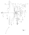
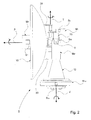
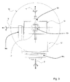
- Fig. 1-3 show different views of a device 1 for controlling a satellite tracking antenna 10 according to a first embodiment of the present invention.
- the azimuth axis drive means M Az constitutes a base.
- the base is arranged to support a support member 12 having a U-shaped configuration, said member being fixed to the base and having legs projecting upwardly from the base.
- the support member 12 is arranged to carry a frame member 13 at an upper portion of said support member by means of the elevation axis Y, the frame member being rotatably arranged about the elevation axis Y.
- the elevation axis Y is thus located at a certain level above the base.
- the frame member 12 is connected to the antenna 10 via the tilt axis T.
- the tilt axis T is connected to the antenna 10 via a first and a second connection member 30, said members 30 being fixed to the antenna and connected to the tilt axis T such that the antenna is rotated when the tilt axis is rotated.
- the azimuth axis drive means M Az is arranged to impart a rotational motion to the base, and thus the support member 12, about the azimuth axis Z.
- the device 1 further comprises an extension 14 rotatably connected to the elevation axis Y and fixed to the antenna 10.
- the elevation axis drive means comprises an elevation motor M E1 arranged to impart a rotational motion to the frame member, and thus the antenna 10, about the elevation axis Y, the motor being connected to the elevation axis Y at a side of the support member.
- the tilt axis drive means comprises a tilt motor M T arranged centrally relative to the azimuth axis and in the area of the tilt axis T.
- the tilt motor is arranged to impart a rotational motion to the antenna by means of rotating the tilt axis.
- a transmission means is arranged to impart the rotational motion of the tilt axis T, said transmission means here being a belt, but could alternatively e.g. be a gear configuration.
- the drive means are supplied by power means not shown.
- Fig. 4 shows schematically a plan view of a device 2 for controlling a satellite tracking antenna 10 according to a second embodiment of the present invention.
- the azimuth axis drive means M Az constitutes a base.
- the azimuth axis drive means M Az is arranged to impart a rotational motion to the base about the azimuth axis Z.
- the device further comprises an extension 14 rotationally connected to the elevation axis Y.
- the tilt axis T is connected to the elevation axis Y by means of said extension 14.
- the elevation axis drive means comprises a first and a second elevation motor M E1 arranged to impart a rotational motion to the extension 14, and thus the antenna 10, about the elevation axis Y, the first and second motor being connected to the elevation axis Y at each side of the elevation axis, respectively.
- the elevation axis drive means comprises a single motor arranged to impart a rotational motion to the elevation arm 14 about the elevation axis, the motor being connected to a side of the elevation axis.
- the tilt axis drive means comprises a tilt motor M T arranged to drive a transmission means constituted by a belt 16, said belt having a first and a second end, said first end being fixed to the antenna at a first connection point 18 and said second end being fixed to the antenna at a second connection point 20.
- the connection points are located at a first and a second side of the tilt axis T such that when the tilt motor ml is driven the antenna is tilted about the tilt axis T by means of the belt 16.
- the tilt motor M T is arranged on the elevation arm 14.
- the tilt motor ml is centrally arranged such that at an elevation angle of 0° it is arrange to rotate the belt 16 about the azimuth axis Z, and at an elevation angle of 90° it is arranged to rotate the belt about the roll axis X.
- the tilt motor is supplied by a power supply 22.
- Fig. 5 shows schematically a plan view of a device 3 according to a third embodiment of the present invention.
- the azimuth axis drive means M Az constitutes a base, and is arranged to impart a rotational motion to the base about the azimuth axis.
- the elevation axis drive means M E1 is arranged to impart a rotational motion about the elevation axis Y.
- the device further comprises an extension 15 connected to the elevation axis drive means M E1 .
- the tilt axis T is connected to the elevation axis Y by means of said extension 15.
- the tilt axis T is directly associated with the antenna 10, such that the antenna is rotatable about the tilt axis T.
- the elevation axis drive means comprises an elevation motor M E1 , arranged to impart a rotational motion about the elevation axis Y, and thus to the antenna 10 via the extension 15.
- the tilt axis drive means comprises a first and second tilt motor M T1 , M T2 .
- the first motor M T1 is arranged to drive a transmission means constituted by a first belt 16a being fixed to the antenna 10 at a first connection point 18 and the second motor M T2 is arranged to drive a second belt 16b being fixed to the antenna at a second connection point 20.
- the connection points are located at a first and a second side of the tilt axis T such that when the motors are driven the antenna 10 is tilted about the tilt axis T by means of the belts 16a, 16b.
- the tilt motors M T1 , M T2 are arranged on each side of the elevation motor M E1 , respectively.
- the motors are powered by a common power supply 22 such that the first motor operates in inverse to the second motor, by means of inverting one of the motors with inversion means 24, i.e. when one motor is arranged to pull the belt the other motor is arranged to release the belt to the same extent.
- the tilt axis T is directly associated to the antenna 10 such that, at an elevation angle of 0°, the tilt axis constitutes the vertical axis of the antenna, and, at an elevation angle of 90°, the tilt axis constitutes the horizontal axis or x-axis of the antenna.
- the antenna 10 when rotated about the tilt axis is rotated about its own axis.
- the tilt axis drive means may comprise a tilt motor arranged to drive an endless belt, said belt being arranged about the tilt axis.
- the tilt axis may be connected to the antenna via a connection member, said member being fixed to the antenna such that when operated, the tilt motor imparts a rotational motion to the tilt axis, and thus the antenna via the connection member, by means of the belt.
- the tilt axis is connected to the antenna via a connection member, said member being fixed to the antenna.
- the endless belt may be used having the tilt axis located in accordance with the first embodiment, directly associated with the antenna, said belt being arranged about a tilt axis.
- the antenna is then intended to be fixed to the tilt axis.
- the tilt motor When operated, the tilt motor imparts a rotational motion to the tilt axis, and thus the antenna, by means of the belt.
- one belt may be used, said belt being arranged about the tilt axis.
- the antenna is intended to be fixed to the tilt axis.
- the tilt motor When operated, the tilt motor imparts a rotational motion to the tilt axis member, and thus the antenna, by means of the belt.
- connection member may be applied to the second and third embodiments such that the connection member is fixed to the antenna, and the belt is fixed at a first and second connection point to the connection member.
- the connection points are located at a first and a second side of the tilt axis such that when the motors are driven the connection member is rotated about the tilt axis, and thus the antenna is rotated about the tilt axis by means of the belt/belts.
- Any type of drive means facilitating imparting a rotational motion to the antenna about the tilt axis may be used.
- a gear type drive means, or drive means of linear motor type may alternatively be used.
- the device is intended to be arranged on a vehicle.
- the device according to the present invention including the feature of the polarisation drive means, may be applied in e.g. a war zone where it is desired to be able to transmit during movement in rough terrain involving elevation angles above 45° and roll motions, and also in other applications such as television broadcasting, fire fighting and the like under above mentioned conditions, where the possibility of transmitting during movement is desired. This is due to the fact that the requirements for transmitting/broadcasting are fulfilled due to the improved response time, and thus there will be no noise transmitted to adjacent channels.
Landscapes
- Physics & Mathematics (AREA)
- Engineering & Computer Science (AREA)
- Astronomy & Astrophysics (AREA)
- General Physics & Mathematics (AREA)
- Remote Sensing (AREA)
- Aviation & Aerospace Engineering (AREA)
- Variable-Direction Aerials And Aerial Arrays (AREA)
Abstract
Description
- The present invention relates to a device for controlling a satellite tracking antenna according to the preamble of
claim 1. The present invention further relates to a method according to the preamble of 8. The present invention further relates to a vehicle according to the preamble ofclaim 13. - In order to automatically track the position of a satellite, satellite receivers are installed in moving objects such as vehicles, ships or the like. A device comprises means for adjusting azimuth angle and elevation angle of the antenna such that the position of the satellite is automatically tracked without adjustment of the wave-receiving angle of the antenna.
- The use of such a two-axis system on a moving vehicle requires, in order to maintaining contact with the satellite, that the direction vector all the time is kept parallel. To accomplish this with such a two-axis system roll movements are compensated by means of an azimuth motor which imparts a rotational motion to the antenna about an azimuth axis and an elevation motor which imparts a rotational motion to the antenna about an elevation axis. Such systems are well known.
- However, at an elevation angle above 45° the response between roll motion and required compensation in azimuth and elevation direction becomes too large. At an elevation angle of 45° the response is 1:1, i.e. a roll motion of x°/s needs compensation in azimuth direction of x°/s. At an elevation angle larger than 45° the response increases and at an elevation angle of 90° the response is infinite. At an elevation angle of 90° there is thus a singularity. This above mentioned problem is referred to as the zenith problem.
- In order to take the polarization in to consideration such systems further comprises means for adjusting the polarization angle of the transceiver head of the antenna, by means of imparting a rotational motion to the transceiver head about a polarization axis. This improves the possibilities of communicating with a satellite such that it is possible to both receive and transmit signals, also during movement, during conditions not involving the above mentioned zenith problem. However, at elevation angles above 45° involving roll motions such a three axis system does not work due to the above mentioned limitation in response. The requirements for transmitting/broadcasting are strict and during movement in these conditions such a system does not meet these requirements, as there will be noise transmitted to adjacent channels due to the limitation in tracking the antenna. Thus, the vehicle would have to stand still. However, in e.g. a war zone it may be desired to be able to transmit during movement when tracking a satellite at an elevation angle above 45°, in rough terrain involving roll motions. Also in other applications such as television broadcasting, fire fighting and the like the possibility of transmitting during movement in such conditions may be requested.
- An object of the present invention is to provide a device for controlling a satellite tracking antenna which is operable at all elevation angles, i.e. also at elevation angles above 45°, solving the so called zenith problem.
- Another object of the present invention is to provide a method for controlling a satellite tracking antenna which is operable at all elevation angles, i.e. at also elevation angles above 45°, solving the so called zenith problem.
- This and other objects, apparent from the following description, are achieved by a device and method for controlling a satellite tracking antenna, and a vehicle with said device, which are of the type stated by way of introduction and which in addition exhibits the features recited in the characterising clause of the appended
claims - Particularly an object is achieved by a device for controlling a satellite tracking antenna comprising an azimuth drive means configured to impart an azimuthal rotational motion to the antenna about an azimuth axis, an elevation axis drive means configured to impart a rotational motion to the antenna about an elevation axis orthogonal to the azimuth axis control means for controlling the operation of the azimuth axis drive means and of the elevation axis drive means, wherein a tilt axis drive means is configured to impart a rotational motion to the antenna about a tilt axis, the tilt axis being connected to the elevation axis in such a way that the rotational freedom of motion of the antenna about the tilt axis is dependent on the elevation angle such that: at an elevation angle of 0° the rotational freedom of motion of the antenna about the tilt axis corresponds to the azimuthal rotational motion; at an increasing elevation angle the rotational freedom of motion about the antenna successively transcends into a roll rotation; and at an elevation angle of 90° the rotational freedom of motion of the antenna about the tilt axis corresponds to a roll rotation, control means being provided for controlling the tilt axis drive means.
- By means of this device an excessively determined system is achieved which solves the so called zenith problem, in that compensation is achieved by means of rotating the antenna about the tilt axis. The stabilizing performance is increased. This further facilitates providing a satellite tracking antenna which, during movement apart from receiving information also is able to transmit information, when compensation of polarization is taken into consideration, even at elevation angles above 45°. The introduction of the tilt axis further reduces the need to moving the rest of the system, thus reducing mass moment of inertia. The invention thus facilitates providing an improved control system to the device. Further, drive means of less effect is thus required facilitating providing a more compact design. Thus a lighter device is further achieved.
- Preferably said antenna is arranged at a distance from said elevation axis. The freedom of motion of the antenna about the tilt axis is increased.
- Preferably said tilt axis is connected to the antenna via a connection member, said member being fixed to the antenna. This simplifies construction and drive transmission.
- Alternatively said tilt axis is directly associated with the antenna. This gives a quick response, due to lower moment of inertia.
- Preferably said tilt axis drive means comprises a transmission means, said transmission means being arranged to impart the rotational motion to the antenna. This facilitates arranging the tilt axis at a distance without having to arrange the drive means at the tilt axis, thus facilitating arranging the tilt axis drive means centrally, reducing moment of inertia.
- Preferably said tilt axis drive means comprises at least one motor arranged in the area of the elevation axis, preferably centrally arranged relative to the roll axis. This reduces the mass moment of inertia, and thus reduces required effect of drive means, facilitating a more compact and lighter design.
- Preferably the device further comprises a polarization axis drive means configured to impart a rotational motion to a transceiver head of the antenna about a polarization axis orthogonal to the tilt axis, wherein the polarisation axis is connected to the tilt axis. This further provides a satellite tracking antenna which, during movement, apart from receiving information also is able to transmit information, even at elevation angles above 45° involving roll motions.
- Particularly another object is achieved by a method for controlling a satellite tracking antenna comprising the steps of imparting an azimuthal rotational motion to the antenna about an azimuth axis, imparting a rotational motion to the antenna about an elevation axis orthogonal to the azimuth axis, and the additional step of imparting a rotational motion to the antenna about a tilt axis, the tilt axis being connected to the elevation axis in such a way that the rotational freedom of motion of the antenna about the tilt axis is dependent on the elevation angle such that: at an elevation angle of 0° the rotational freedom of motion of the antenna about the tilt axis corresponds to the azimuthal rotational motion; at an increasing elevation angle the rotational freedom of motion about the antenna successively transcends into a roll rotation; and at an elevation angle of 90° the rotational freedom of motion of the antenna about the tilt axis corresponds to a roll rotation. By means of this method an excessively determined system is achieved which solves the so called zenith problem, in that compensation is achieved by means of rotating the antenna about the tilt axis. The stabilizing performance is increased. This further facilitates providing a satellite tracking antenna which, during movement apart from receiving information also is able to transmit information, when compensation of polarization is taken into consideration. The introduction of the tilt axis further reduces the need to moving the rest of the system, thus reducing mass moment of inertia. The invention thus facilitates providing an improved control system to the device. Further drive means of less effect is thus required facilitating providing a more compact design. Thus a lighter device may further be provided.
- Preferably the method comprises the step of arranging said antenna at a distance from said elevation axis. The freedom of motion of the antenna about the tilt axis is increased.
- Preferably the method comprises the step connecting said tilt axis to the antenna via a connection member, fixing said member to the antenna. This simplifies construction and drive transmission.
- Alternatively the method comprises the step directly associating said tilt axis with the antenna. This gives a quick response, due to lower moment of inertia.
- Preferably the method further comprises the step of imparting a rotational motion to the a transceiver head of the antenna about a polarization axis orthogonal to the tilt axis, wherein the polarisation axis is connected to the tilt axis. This further provides a satellite tracking antenna which, during movement, apart from receiving information also is able to transmit information, even at elevation angles above 45° involving roll motions.
- A better understanding of the present invention will be had upon the reference to the following detailed description when read in conjunction with the accompanying drawings, wherein like reference characters refer to like parts throughout the several views, and in which:
-
Fig. 1 schematically shows a plan view of a device according to a first embodiment of the present invention; -
Fig. 2 schematically shows a side view of the device infig. 1 ; -
Fig. 3 schematically shows a back view of the device infig. 1 ; -
Fig. 4 schematically shows a plan view of a device according to a second embodiment of the present invention; and -
Fig. 5 schematically shows a plan view of a device according to a third embodiment of the present invention. -
Fig. 1-5 show embodiments 1; 2; 3 of the device according to the present invention. Generally, as can be seen fromfig. 1-5 , the device comprises an azimuth drive means MAz configured to impart an azimuthal rotational motion to anantenna 10 about an azimuth axis Z, an elevation axis drive means ME1 configured to impart a rotational motion to the antenna about an elevation axis Y, orthogonal to the azimuth axis Z, a tilt axis drive means MT; MT1, MT2 configured to impart a rotational motion to the antenna about a tilt axis T, and a polarization axis drive means MP configured to impart a rotational motion to atransceiver head 11 of the antenna about a polarization axis P, orthogonal to the tilt axis T. Theantenna 10 comprises a parabola and, thus, atransceiver head 11, i.e. theantenna 10 is configured to both transmit and receive signals/information. Preferably the transceiver head is rotatable about the polarization axis relative to the parabola, i.e. the parabola does not need to rotate as the transceiver head rotates. - The tilt axis T is connected to the elevation axis Y in such a way that the rotational freedom of motion of the
antenna 10 about the tilt axis T is dependent on the elevation angle such that, at an elevation angle of 0° the rotational freedom of motion of the antenna about the tilt axis T corresponds to the azimuthal rotational motion, and at an increasing elevation angle the rotational freedom of motion of the antenna about the tilt axis T successively transcend into a roll rotation, and at an elevation angle of 90° the rotational freedom of motion of the antenna about the tilt axis T is a roll rotation, i.e. corresponds to the roll rotation of the antenna about a roll axis X. Thus, at an en elevation angle of 0° the tilt axis T is parallel to the azimuth axis Z, and at an elevation angle of 90° the tilt axis T is parallel to the roll axis X. Thus, an excessively determined system is provided by means of the tilt axis T. - The polarisation axis P is connected to the tilt axis T in such a way that the rotational freedom of motion of the
transceiver head 11 of theantenna 10 about the polarization axis P is dependant on the elevation angle and the tilt angle such that, when the tilt angle is 0°, at an elevation angle of 0° the rotational freedom of motion of thetransceiver head 11 about the polarization axis corresponds to a roll rotation about the roll axis X, and at an increasing elevation angle the rotational freedom of motion of thetransceiver head 11 about the polarization axis transcend into, and at an elevation angle of 90° corresponds to a rotation about an azimuth axis Z. Thus, when the tilt angle is 0°, at an en elevation angle of 0° the polarization axis is parallel to the roll axis X, and at an elevation angle of 90° the polarization axis P is parallel to the azimuth axis Z. At, as an extreme, a tilt angle of 90° the polarization axis P is parallel to the elevation axis Y. The polarization axis P is thus orthogonal to the tilt axis T. The polarization axis is during operation all the time intended to point in the direction of the satellite. - The
device 1; 2; 3 further comprises means for controlling operation of the azimuth axis drive means MAz, the elevation axis drive means ME1, the polarization axis drive means Mp and the tilt axis drive means MT; MT1, MT2. The control means comprises anavigation system 100, schematically shown infig. 1 , arranged to provide bearing, elevation (pitch) and roll to the device relative to the horizontal plane of the earth. Preferably the navigation system is a heading reference gyro. The navigation system needs to be aligned with the pointing direction of the transceiver head. The navigation system is preferably arranged proximate to the drive means, which simplifies mechanical alignment, but it may also be arranged at a distance from the drive means. - The control means further comprises absolute angle sensors SAz, SE1, ST, SP, schematically shown in
fig. 2 , arranged to sense angles of rotation and transform the vector of direction in order to give the spatial tracking direction. The angle sensors are preferably encoders or resolvers. The location of the angle sensors may vary depending on design. The angles provided from the angle sensors are used to calculate the pointing direction of the antenna in the horizontal system of the earth, i.e. north, up, west, etc., i.e. an inertial frame, by means of the angles of thenavigation system 100 and coordinate transformations. More specifically the control means comprises an azimuth angle sensor SAz arranged to sense the angle of rotation about the azimuth axis Z, an elevation angle sensor SE1 arranged to sense the angle of rotation about the elevation axis Y, a tilt angle sensor ST arranged to sense the angle of rotation about the tilt axis T, and a polarization angle sensor SP arranged to sense the angle of rotation about the polarization axis P. Preferably the control means comprises three gyro axes GE1, GT and GP, an elevation gyro axis GE1 arranged to be synchronized with the elevation movement, a tilt gyro axis GT arranged to be synchronized with the tilt movement, and a polarization gyro axis GP arranged to be synchronized with the polarization movement. The gyro axes are schematically shown infig. 1 . The gyro axes improve the stabilizing performance of the device. As the azimuth rotation does not have to be precisely controlled an azimuth gyro axis is not required, but could be provided if desired. - Preferably the azimuth drive means is arranged at the "bottom" of the device, followed by the elevation drive means, the tilt drive means and the polarization drive means. Having the drive means arranged in this order, drive means of less effect, i.e. smaller motors, is required the higher up in the order, facilitating providing an improved control system to the device. Thus, the tilt and polarization drive means may be of small effect, i.e. small motors, for rotating the antenna, which preferably is made of light weight material.
- When operated the device according to the present invention is intended to provide an azimuthal rotational motion of n x 360°, an elevational rotational motion of -30° to 210°, a tilt rotational motion of -45 to 45° for application on land, and a tilt rotational motion of -60° to 60° for application on the sea, and a polarizational rotational motion of n x 360°. However, if desired, other operational angles may be provided.
-
Fig. 1-3 show different views of adevice 1 for controlling asatellite tracking antenna 10 according to a first embodiment of the present invention. The azimuth axis drive means MAz constitutes a base. The base is arranged to support asupport member 12 having a U-shaped configuration, said member being fixed to the base and having legs projecting upwardly from the base. Thesupport member 12 is arranged to carry aframe member 13 at an upper portion of said support member by means of the elevation axis Y, the frame member being rotatably arranged about the elevation axis Y. The elevation axis Y is thus located at a certain level above the base. Theframe member 12 is connected to theantenna 10 via the tilt axis T. The tilt axis T is connected to theantenna 10 via a first and asecond connection member 30, saidmembers 30 being fixed to the antenna and connected to the tilt axis T such that the antenna is rotated when the tilt axis is rotated. The azimuth axis drive means MAz is arranged to impart a rotational motion to the base, and thus thesupport member 12, about the azimuth axis Z. Thedevice 1 further comprises anextension 14 rotatably connected to the elevation axis Y and fixed to theantenna 10. The elevation axis drive means comprises an elevation motor ME1 arranged to impart a rotational motion to the frame member, and thus theantenna 10, about the elevation axis Y, the motor being connected to the elevation axis Y at a side of the support member. - In this embodiment the tilt axis drive means comprises a tilt motor MT arranged centrally relative to the azimuth axis and in the area of the tilt axis T. The tilt motor is arranged to impart a rotational motion to the antenna by means of rotating the tilt axis. A transmission means is arranged to impart the rotational motion of the tilt axis T, said transmission means here being a belt, but could alternatively e.g. be a gear configuration. The drive means are supplied by power means not shown.
-
Fig. 4 shows schematically a plan view of adevice 2 for controlling asatellite tracking antenna 10 according to a second embodiment of the present invention. The azimuth axis drive means MAz constitutes a base. The azimuth axis drive means MAz is arranged to impart a rotational motion to the base about the azimuth axis Z. The device further comprises anextension 14 rotationally connected to the elevation axis Y. The tilt axis T is connected to the elevation axis Y by means of saidextension 14. The elevation axis drive means comprises a first and a second elevation motor ME1 arranged to impart a rotational motion to theextension 14, and thus theantenna 10, about the elevation axis Y, the first and second motor being connected to the elevation axis Y at each side of the elevation axis, respectively. Alternatively the elevation axis drive means comprises a single motor arranged to impart a rotational motion to theelevation arm 14 about the elevation axis, the motor being connected to a side of the elevation axis. - In this embodiment the tilt axis drive means comprises a tilt motor MT arranged to drive a transmission means constituted by a
belt 16, said belt having a first and a second end, said first end being fixed to the antenna at afirst connection point 18 and said second end being fixed to the antenna at asecond connection point 20. The connection points are located at a first and a second side of the tilt axis T such that when the tilt motor ml is driven the antenna is tilted about the tilt axis T by means of thebelt 16. The tilt motor MT is arranged on theelevation arm 14. The tilt motor ml is centrally arranged such that at an elevation angle of 0° it is arrange to rotate thebelt 16 about the azimuth axis Z, and at an elevation angle of 90° it is arranged to rotate the belt about the roll axis X. The tilt motor is supplied by apower supply 22. -
Fig. 5 shows schematically a plan view of adevice 3 according to a third embodiment of the present invention. The azimuth axis drive means MAz constitutes a base, and is arranged to impart a rotational motion to the base about the azimuth axis. The elevation axis drive means ME1 is arranged to impart a rotational motion about the elevation axis Y. The device further comprises anextension 15 connected to the elevation axis drive means ME1. The tilt axis T is connected to the elevation axis Y by means of saidextension 15. The tilt axis T is directly associated with theantenna 10, such that the antenna is rotatable about the tilt axis T. The elevation axis drive means comprises an elevation motor ME1, arranged to impart a rotational motion about the elevation axis Y, and thus to theantenna 10 via theextension 15. - In this embodiment the tilt axis drive means comprises a first and second tilt motor MT1, MT2. The first motor MT1 is arranged to drive a transmission means constituted by a
first belt 16a being fixed to theantenna 10 at afirst connection point 18 and the second motor MT2 is arranged to drive asecond belt 16b being fixed to the antenna at asecond connection point 20. The connection points are located at a first and a second side of the tilt axis T such that when the motors are driven theantenna 10 is tilted about the tilt axis T by means of thebelts common power supply 22 such that the first motor operates in inverse to the second motor, by means of inverting one of the motors with inversion means 24, i.e. when one motor is arranged to pull the belt the other motor is arranged to release the belt to the same extent. - In
fig. 4 and5 the navigation system, the angle sensors and the gyro axes are not shown. - In the second and third embodiments in
fig. 4 and5 , the tilt axis T is directly associated to theantenna 10 such that, at an elevation angle of 0°, the tilt axis constitutes the vertical axis of the antenna, and, at an elevation angle of 90°, the tilt axis constitutes the horizontal axis or x-axis of the antenna. Thus theantenna 10 when rotated about the tilt axis is rotated about its own axis. - As an alternative to the second and third embodiment of
fig. 4 and5 the tilt axis drive means may comprise a tilt motor arranged to drive an endless belt, said belt being arranged about the tilt axis. The tilt axis may be connected to the antenna via a connection member, said member being fixed to the antenna such that when operated, the tilt motor imparts a rotational motion to the tilt axis, and thus the antenna via the connection member, by means of the belt. The tilt axis is connected to the antenna via a connection member, said member being fixed to the antenna. - As an alternative to the connection member the endless belt may be used having the tilt axis located in accordance with the first embodiment, directly associated with the antenna, said belt being arranged about a tilt axis. The antenna is then intended to be fixed to the tilt axis. When operated, the tilt motor imparts a rotational motion to the tilt axis, and thus the antenna, by means of the belt.
- As an alternative to the two belts in
fig. 4 , one belt may be used, said belt being arranged about the tilt axis. The antenna is intended to be fixed to the tilt axis. When operated, the tilt motor imparts a rotational motion to the tilt axis member, and thus the antenna, by means of the belt. - Alternatively the connection member may be applied to the second and third embodiments such that the connection member is fixed to the antenna, and the belt is fixed at a first and second connection point to the connection member. The connection points are located at a first and a second side of the tilt axis such that when the motors are driven the connection member is rotated about the tilt axis, and thus the antenna is rotated about the tilt axis by means of the belt/belts.
- Any type of drive means facilitating imparting a rotational motion to the antenna about the tilt axis may be used. For example, a gear type drive means, or drive means of linear motor type may alternatively be used.
- The device is intended to be arranged on a vehicle. Advantageously the device according to the present invention, including the feature of the polarisation drive means, may be applied in e.g. a war zone where it is desired to be able to transmit during movement in rough terrain involving elevation angles above 45° and roll motions, and also in other applications such as television broadcasting, fire fighting and the like under above mentioned conditions, where the possibility of transmitting during movement is desired. This is due to the fact that the requirements for transmitting/broadcasting are fulfilled due to the improved response time, and thus there will be no noise transmitted to adjacent channels.
- The foregoing description of the preferred embodiments of the present invention has been provided for the purposes of illustration and description. It is not intended to be exhaustive or to limit the invention to the precise forms disclosed. Obviously, many modifications and variations will be apparent to practitioners skilled in the art. The embodiments were chosen and described in order to best explain the principles of the invention and its practical applications, thereby enabling others skilled in the art to understand the invention for various embodiments and with the various modifications as are suited to the particular use contemplated.
Claims (13)
- A device for controlling a satellite tracking antenna (10) comprising an azimuth drive means (MAz) configured to impart an azimuthal rotational motion to the antenna about an azimuth axis (Z), an elevation axis drive means (ME1) configured to impart a rotational motion to the antenna about an elevation axis (Y) orthogonal to the azimuth axis and control means for controlling the operation of the azimuth axis drive means and of the elevation axis drive means, characterised by a tilt axis drive means (MT; MT1, MT2) configured to impart a rotational motion to the antenna about a tilt axis (T), the tilt axis being connected to the elevation axis in such a way that the rotational freedom of motion of the antenna (19) about the tilt axis (T) is dependent on the elevation angle such that:- at an elevation angle of 0° the rotational freedom of motion of the antenna (10) about the tilt axis (T) corresponds to the azimuthal rotational motion;- at an increasing elevation angle the rotational freedom of motion about the antenna (10) successively transcends into a roll rotation; and- at an elevation angle of 90° the rotational freedom of motion of the antenna about the tilt axis (T) corresponds to a roll rotation,control means being provided for controlling the tilt axis drive means.
- A device according to claim 1, wherein said antenna (10) is arranged at a distance from said elevation axis (Y).
- A device according to claim 1 or 2, wherein said tilt axis (T) is connected to the antenna (10) via a connection member (30), said member being fixed to the antenna.
- A device according to claim 1 or 2, wherein said tilt axis (T) is directly associated with the antenna (10).
- A device according to claims 1-4, wherein said tilt axis drive means (MT; MT1, MT2) comprises a transmission means (16; 16a, 16b), said transmission means being arranged to impart the rotational motion to the antenna (10).
- A device according to claims 1-5, wherein said tilt axis drive means (MT; MT1, MT2) comprises at least one motor (MT; MT1, MT2) arranged in the area of the elevation axis (Y), preferably centrally arranged relative to the roll axis (X).
- A device according to claims 1-6, further comprising a polarization axis drive means configured to impart a rotational motion to a transceiver head of the antenna about a polarization axis (P) orthogonal to the tilt axis (T), wherein the polarisation axis (P) is connected to the tilt axis (T), control means being provided for controlling the polarization axis drive means.
- A method for controlling a satellite tracking antenna (10) comprising the steps of imparting an azimuthal rotational motion to the antenna (10) about an azimuth axis (Z), imparting a rotational motion to the antenna about an elevation axis (Y) orthogonal to the azimuth axis (Z), characterised by the additional step of imparting a rotational motion to the antenna (10) about a tilt axis (T), the tilt axis being connected to the elevation axis (Y) in such a way that the rotational freedom of motion of the antenna (10) about the tilt axis is dependent on the elevation angle such that:- at an elevation angle of 0° rotational freedom of motion of the antenna (10) about the tilt axis (T) corresponds to the azimuthal rotational motion;- at an increasing elevation angle the rotational freedom of motion about the antenna (10) successively transcends into a roll rotation; and- at an elevation angle of 90° the rotational freedom of motion of the antenna about the tilt axis (T) corresponds to a roll rotation.
- A method according to claim 8, further comprising the step of locating said tilt axis (T) at a distance from said elevation axis (Y).
- A method according to claim 8 or 9, further comprising the step of directly associating said tilt axis (T) with the antenna (10).
- A method according to claim 8 or 9, further comprising the step of connecting the tilt axis (T) to the antenna (10) via a connection member (30), fixing said member to the antenna (10).
- A method according to any of claims 8-11, further comprising the step of imparting a rotational motion to a transceiver head of the antenna (10) about a polarization axis (P) orthogonal to the tilt axis (T), wherein the polarisation axis (P) is connected to the tilt axis (T).
- Vehicle comprising a device according to claims 1-7.
Priority Applications (6)
| Application Number | Priority Date | Filing Date | Title |
|---|---|---|---|
| EP07106911A EP1986016A1 (en) | 2007-04-25 | 2007-04-25 | Device and method for controlling a satellite tracking antenna |
| PCT/EP2008/055021 WO2008132141A1 (en) | 2007-04-25 | 2008-04-24 | Device and method for controlling a satellite tracking antenna |
| AU2008244292A AU2008244292B2 (en) | 2007-04-25 | 2008-04-24 | Device and method for controlling a satellite tracking antenna |
| US12/597,650 US8149176B2 (en) | 2007-04-25 | 2008-04-24 | Device and method for controlling a satellite tracking antenna |
| EP08749711.1A EP2145202B1 (en) | 2007-04-25 | 2008-04-24 | Device and method for controlling a satellite tracking antenna |
| ZA200907221A ZA200907221B (en) | 2007-04-25 | 2009-10-15 | Device and method for controlling a satellite tracking antenna |
Applications Claiming Priority (1)
| Application Number | Priority Date | Filing Date | Title |
|---|---|---|---|
| EP07106911A EP1986016A1 (en) | 2007-04-25 | 2007-04-25 | Device and method for controlling a satellite tracking antenna |
Publications (1)
| Publication Number | Publication Date |
|---|---|
| EP1986016A1 true EP1986016A1 (en) | 2008-10-29 |
Family
ID=38016836
Family Applications (2)
| Application Number | Title | Priority Date | Filing Date |
|---|---|---|---|
| EP07106911A Withdrawn EP1986016A1 (en) | 2007-04-25 | 2007-04-25 | Device and method for controlling a satellite tracking antenna |
| EP08749711.1A Active EP2145202B1 (en) | 2007-04-25 | 2008-04-24 | Device and method for controlling a satellite tracking antenna |
Family Applications After (1)
| Application Number | Title | Priority Date | Filing Date |
|---|---|---|---|
| EP08749711.1A Active EP2145202B1 (en) | 2007-04-25 | 2008-04-24 | Device and method for controlling a satellite tracking antenna |
Country Status (5)
| Country | Link |
|---|---|
| US (1) | US8149176B2 (en) |
| EP (2) | EP1986016A1 (en) |
| AU (1) | AU2008244292B2 (en) |
| WO (1) | WO2008132141A1 (en) |
| ZA (1) | ZA200907221B (en) |
Cited By (6)
| Publication number | Priority date | Publication date | Assignee | Title |
|---|---|---|---|---|
| EP2395600A1 (en) * | 2010-06-14 | 2011-12-14 | Orbit Communication Ltd. | Effective marine stabilized antenna system |
| CN105491586A (en) * | 2015-12-08 | 2016-04-13 | 广东怡创科技股份有限公司 | Method and system for measuring azimuth angle of cell base station antenna |
| WO2018236270A1 (en) * | 2017-06-22 | 2018-12-27 | Saab Ab | ARRANGEMENT AND METHOD FOR SELF-ALIGNING A STABILIZED SUBSYSTEM |
| CN109301452A (en) * | 2018-09-19 | 2019-02-01 | 中国科学院遥感与数字地球研究所 | S/X/Ka Triaxial Antenna |
| CN110809277A (en) * | 2019-12-16 | 2020-02-18 | 中国联合网络通信集团有限公司 | Optimization method and device for base station |
| CN116722361B (en) * | 2023-07-18 | 2023-12-19 | 中国船舶集团有限公司第七二三研究所 | Antenna polarization stabilizing device and method under swinging platform |
Families Citing this family (24)
| Publication number | Priority date | Publication date | Assignee | Title |
|---|---|---|---|---|
| ES2407830T3 (en) * | 2008-08-28 | 2013-06-14 | Saab Ab | A goal tracking system and a procedure for tracking a goal |
| US9000995B2 (en) * | 2010-06-27 | 2015-04-07 | Sea Tel, Inc. | Three-axis pedestal having motion platform and piggy back assemblies |
| CN102360231B (en) * | 2011-06-16 | 2013-04-10 | 成都西科微波通讯有限公司 | Rate gyroscope-based flexible antenna servo control system |
| KR101289058B1 (en) * | 2011-11-04 | 2013-07-22 | 위월드 주식회사 | Auto positioning antenna system and method for multi satellite |
| CN103138050B (en) * | 2013-02-27 | 2015-01-14 | 宁波森富机电制造有限公司 | Three-axis stable follow-up tracking device of shipborne satellite antenna |
| EP3036794A4 (en) | 2013-06-11 | 2017-06-14 | E M Solutions Pty Ltd | A stabilized platform for a wireless communication link |
| CN104064869B (en) * | 2014-06-13 | 2016-10-05 | 北京航天万达高科技有限公司 | Biquaternion antenna for satellite communication in motion control method and system based on MEMS inertial navigation |
| KR101782259B1 (en) * | 2016-04-21 | 2017-09-27 | 한국항공우주연구원 | Apparatus and method for speed controlling of a satellite antenna |
| EP3472893B1 (en) | 2016-06-21 | 2021-08-11 | Thrane & Thrane A/S | An antenna and a method of operating it |
| CN106785442B (en) * | 2016-12-19 | 2020-06-26 | 中云卫星通信有限公司 | Method and system for tracking satellite by vehicle-mounted satellite antenna |
| AU2019231726B2 (en) * | 2018-03-08 | 2023-02-02 | Viasat, Inc. | Antenna positioner with eccentric tilt position mechanism |
| CN108923127B (en) * | 2018-08-17 | 2023-07-25 | 浙江金波电子有限公司 | Four-axis shipborne satellite antenna and control method thereof |
| CN110221317B (en) * | 2018-11-30 | 2023-08-01 | 武汉滨湖电子有限责任公司 | Beidou north-seeking antenna high-precision installation method based on modularization |
| CN109724581B (en) * | 2019-01-11 | 2022-07-19 | 西安超视距航空航天科技有限公司 | Strapdown north-seeking method based on automatic theodolite auxiliary rotation modulation |
| CN112310596B (en) * | 2020-11-19 | 2022-05-17 | 泰州市柯普尼通讯设备有限公司 | Economical simple ship-borne VSAT antenna system |
| WO2022137441A1 (en) * | 2020-12-24 | 2022-06-30 | 日本電信電話株式会社 | Radio communication device and control method |
| CN114204244B (en) * | 2021-11-17 | 2024-12-10 | 北京无线电计量测试研究所 | A beamforming antenna measurement device |
| CN114444279B (en) * | 2022-01-14 | 2022-12-16 | 中国人民解放军国防科技大学 | Response Prediction Method Based on Joint Estimation of Associated Parameters from Satellite Low-precision Data |
| CN115020961B (en) * | 2022-06-28 | 2025-01-24 | 中国科学院空天信息创新研究院 | Antenna rotating installation structure |
| CN115458941B (en) * | 2022-08-31 | 2025-07-11 | 天津航天机电设备研究所 | A multi-degree-of-freedom antenna tracking mechanism |
| CN116613505B (en) * | 2023-06-12 | 2026-02-03 | 中国电子科技集团公司第五十四研究所 | Azimuth-crossing-pitching type seat frame system adapting to extremely high sea conditions |
| CN116953638B (en) * | 2023-07-21 | 2025-09-30 | 中国西安卫星测控中心 | Optimal motion range selection method for coiled antenna of aerospace ground equipment based on single feature point |
| KR102728668B1 (en) * | 2024-03-12 | 2024-11-11 | 주식회사 케이앤에스아이앤씨 | A satellite antenna for direct drive type with tilt structure |
| CN119805506B (en) * | 2025-03-12 | 2026-01-27 | 东方空间技术(山东)有限公司 | Automatic debugging device and method for portable satellite measurement and control antenna |
Citations (5)
| Publication number | Priority date | Publication date | Assignee | Title |
|---|---|---|---|---|
| JPS5136854A (en) * | 1974-09-25 | 1976-03-27 | Japan Radio Co Ltd | SENJOANTEN ASOCHI |
| EP0246635A2 (en) * | 1986-05-21 | 1987-11-25 | Nec Corporation | Tracking controller for three-axis mount antenna systems |
| FR2671885A1 (en) * | 1991-01-17 | 1992-07-24 | Robert Pierre | DEVICE FOR ORIENTATION AND ADJUSTMENT, ACCORDING TO AT LEAST ONE OF THE THREE DIRECTIONS OF SPACE, OF THE POSITION OF A PART, ESPECIALLY OF AN ANTENNA FOR TRANSMISSION OR RECEPTION OF ELECTROMAGNETIC WAVES. |
| EP0756180A1 (en) * | 1995-07-24 | 1997-01-29 | Alcatel Telspace | Method to control an antenna positioner for an orbiting satellite |
| US7095376B1 (en) * | 2004-11-30 | 2006-08-22 | L3 Communications Corporation | System and method for pointing and control of an antenna |
Family Cites Families (10)
| Publication number | Priority date | Publication date | Assignee | Title |
|---|---|---|---|---|
| US4786912A (en) * | 1986-07-07 | 1988-11-22 | Unisys Corporation | Antenna stabilization and enhancement by rotation of antenna feed |
| CA1318394C (en) | 1988-04-12 | 1993-05-25 | Ryuichi Hiratsuka | Antenna apparatus and attitude control method |
| JP2579070B2 (en) | 1991-03-06 | 1997-02-05 | 日本無線株式会社 | Array antenna and swing compensation type antenna device |
| US6285338B1 (en) * | 2000-01-28 | 2001-09-04 | Motorola, Inc. | Method and apparatus for eliminating keyhole problem of an azimuth-elevation gimbal antenna |
| JP2001267830A (en) * | 2000-03-15 | 2001-09-28 | Hitachi Ltd | Antenna driver and satellite tracking system using the same |
| JP2007512757A (en) | 2003-11-27 | 2007-05-17 | ウィワールド カンパニー リミテッド | Improved mobile satellite tracking antenna system and method of operation thereof |
| IL171450A (en) * | 2005-10-16 | 2011-03-31 | Starling Advanced Comm Ltd | Antenna panel |
| KR20070060630A (en) | 2005-12-09 | 2007-06-13 | 한국전자통신연구원 | Satellite tracking antenna system |
| KR100798129B1 (en) | 2006-09-06 | 2008-02-01 | 위월드 주식회사 | Satellite tracking mode selectable satellite antenna system |
| JP5016464B2 (en) * | 2007-12-07 | 2012-09-05 | 古野電気株式会社 | Control method for reducing directivity error of antenna having biaxial gimbal structure and control device including the method |
-
2007
- 2007-04-25 EP EP07106911A patent/EP1986016A1/en not_active Withdrawn
-
2008
- 2008-04-24 US US12/597,650 patent/US8149176B2/en active Active
- 2008-04-24 EP EP08749711.1A patent/EP2145202B1/en active Active
- 2008-04-24 WO PCT/EP2008/055021 patent/WO2008132141A1/en not_active Ceased
- 2008-04-24 AU AU2008244292A patent/AU2008244292B2/en active Active
-
2009
- 2009-10-15 ZA ZA200907221A patent/ZA200907221B/en unknown
Patent Citations (5)
| Publication number | Priority date | Publication date | Assignee | Title |
|---|---|---|---|---|
| JPS5136854A (en) * | 1974-09-25 | 1976-03-27 | Japan Radio Co Ltd | SENJOANTEN ASOCHI |
| EP0246635A2 (en) * | 1986-05-21 | 1987-11-25 | Nec Corporation | Tracking controller for three-axis mount antenna systems |
| FR2671885A1 (en) * | 1991-01-17 | 1992-07-24 | Robert Pierre | DEVICE FOR ORIENTATION AND ADJUSTMENT, ACCORDING TO AT LEAST ONE OF THE THREE DIRECTIONS OF SPACE, OF THE POSITION OF A PART, ESPECIALLY OF AN ANTENNA FOR TRANSMISSION OR RECEPTION OF ELECTROMAGNETIC WAVES. |
| EP0756180A1 (en) * | 1995-07-24 | 1997-01-29 | Alcatel Telspace | Method to control an antenna positioner for an orbiting satellite |
| US7095376B1 (en) * | 2004-11-30 | 2006-08-22 | L3 Communications Corporation | System and method for pointing and control of an antenna |
Cited By (10)
| Publication number | Priority date | Publication date | Assignee | Title |
|---|---|---|---|---|
| EP2395600A1 (en) * | 2010-06-14 | 2011-12-14 | Orbit Communication Ltd. | Effective marine stabilized antenna system |
| US8648748B2 (en) | 2010-06-14 | 2014-02-11 | Orbit Communication Ltd. | Effective marine stabilized antenna system |
| CN105491586A (en) * | 2015-12-08 | 2016-04-13 | 广东怡创科技股份有限公司 | Method and system for measuring azimuth angle of cell base station antenna |
| WO2018236270A1 (en) * | 2017-06-22 | 2018-12-27 | Saab Ab | ARRANGEMENT AND METHOD FOR SELF-ALIGNING A STABILIZED SUBSYSTEM |
| KR20200047518A (en) * | 2017-06-22 | 2020-05-07 | 사브 에이비 | Apparatus and method for automatic alignment of stabilized subsystems |
| US11549785B2 (en) | 2017-06-22 | 2023-01-10 | Saab Ab | Arrangement and method for autoalignment of a stabilized subsystem |
| CN109301452A (en) * | 2018-09-19 | 2019-02-01 | 中国科学院遥感与数字地球研究所 | S/X/Ka Triaxial Antenna |
| CN109301452B (en) * | 2018-09-19 | 2024-02-02 | 中国科学院遥感与数字地球研究所 | S/X/Ka triaxial antenna |
| CN110809277A (en) * | 2019-12-16 | 2020-02-18 | 中国联合网络通信集团有限公司 | Optimization method and device for base station |
| CN116722361B (en) * | 2023-07-18 | 2023-12-19 | 中国船舶集团有限公司第七二三研究所 | Antenna polarization stabilizing device and method under swinging platform |
Also Published As
| Publication number | Publication date |
|---|---|
| AU2008244292A1 (en) | 2008-11-06 |
| US8149176B2 (en) | 2012-04-03 |
| EP2145202B1 (en) | 2018-03-14 |
| EP2145202A1 (en) | 2010-01-20 |
| ZA200907221B (en) | 2010-07-28 |
| AU2008244292B2 (en) | 2012-03-08 |
| US20100201589A1 (en) | 2010-08-12 |
| WO2008132141A1 (en) | 2008-11-06 |
Similar Documents
| Publication | Publication Date | Title |
|---|---|---|
| EP2145202B1 (en) | Device and method for controlling a satellite tracking antenna | |
| US5517205A (en) | Two axis mount pointing apparatus | |
| EP4022799B1 (en) | Yaw drift compensation for pointing an antenna | |
| CN111869003B (en) | Antenna system configured to facilitate simultaneous multi-beam operation with a first satellite and a second satellite | |
| KR100733961B1 (en) | Pedestal device and satellite tracking antenna | |
| US8847845B2 (en) | Holder for a movable sensor | |
| US4786912A (en) | Antenna stabilization and enhancement by rotation of antenna feed | |
| KR100974534B1 (en) | Pitch-roll based antenna tracking gimbal system for continuous rotation of eye vector | |
| US6266029B1 (en) | Luneberg lens antenna with multiple gimbaled RF feeds | |
| IL183453A (en) | Phased array planar antenna for tracking a moving target and tracking method | |
| EP2165111A1 (en) | Method and system for adjusting a position of an object | |
| CN112821029B (en) | Shipborne satellite antenna seat and shipborne satellite antenna tracking system | |
| KR102274504B1 (en) | Satellite antenna system and control method using the same | |
| KR101657176B1 (en) | Pedestal apparatus for satellite tracking antenna | |
| JP3600354B2 (en) | Mobile SNG device | |
| JP2005504670A (en) | Satellite attitude adjustment for GPS initialization | |
| CN113296529B (en) | Phased array antenna for low-orbit satellite communication in motion and control method thereof | |
| US7223063B2 (en) | Method and system for adjusting a position of an object | |
| JP3645376B2 (en) | Antenna device | |
| CN109540171B (en) | Portable autonomous positioning and directional servo system | |
| CN214846391U (en) | Pass-in-motion phased array antenna for low-orbit satellites | |
| JP2015194374A (en) | Radar device and control method for the same | |
| KR100490126B1 (en) | A satellite tracking antenna system for vehicles | |
| JP2015194375A (en) | radar antenna device | |
| JP3428858B2 (en) | Three-axis controller for directional antenna |
Legal Events
| Date | Code | Title | Description |
|---|---|---|---|
| PUAI | Public reference made under article 153(3) epc to a published international application that has entered the european phase |
Free format text: ORIGINAL CODE: 0009012 |
|
| AK | Designated contracting states |
Kind code of ref document: A1 Designated state(s): AT BE BG CH CY CZ DE DK EE ES FI FR GB GR HU IE IS IT LI LT LU LV MC MT NL PL PT RO SE SI SK TR |
|
| AX | Request for extension of the european patent |
Extension state: AL BA HR MK RS |
|
| 17P | Request for examination filed |
Effective date: 20090416 |
|
| 17Q | First examination report despatched |
Effective date: 20090513 |
|
| AKX | Designation fees paid |
Designated state(s): AT BE BG CH CY CZ DE DK EE ES FI FR GB GR HU IE IS IT LI LT LU LV MC MT NL PL PT RO SE SI SK TR |
|
| STAA | Information on the status of an ep patent application or granted ep patent |
Free format text: STATUS: THE APPLICATION IS DEEMED TO BE WITHDRAWN |
|
| 18D | Application deemed to be withdrawn |
Effective date: 20091124 |