EP1985910A2 - Tilting mechanism and electronic apparatus - Google Patents
Tilting mechanism and electronic apparatus Download PDFInfo
- Publication number
- EP1985910A2 EP1985910A2 EP08150010A EP08150010A EP1985910A2 EP 1985910 A2 EP1985910 A2 EP 1985910A2 EP 08150010 A EP08150010 A EP 08150010A EP 08150010 A EP08150010 A EP 08150010A EP 1985910 A2 EP1985910 A2 EP 1985910A2
- Authority
- EP
- European Patent Office
- Prior art keywords
- guide
- shafts
- concave portion
- base
- guide grooves
- Prior art date
- Legal status (The legal status is an assumption and is not a legal conclusion. Google has not performed a legal analysis and makes no representation as to the accuracy of the status listed.)
- Withdrawn
Links
Images








Classifications
-
- F—MECHANICAL ENGINEERING; LIGHTING; HEATING; WEAPONS; BLASTING
- F16—ENGINEERING ELEMENTS AND UNITS; GENERAL MEASURES FOR PRODUCING AND MAINTAINING EFFECTIVE FUNCTIONING OF MACHINES OR INSTALLATIONS; THERMAL INSULATION IN GENERAL
- F16M—FRAMES, CASINGS OR BEDS OF ENGINES, MACHINES OR APPARATUS, NOT SPECIFIC TO ENGINES, MACHINES OR APPARATUS PROVIDED FOR ELSEWHERE; STANDS; SUPPORTS
- F16M11/00—Stands or trestles as supports for apparatus or articles placed thereon ; Stands for scientific apparatus such as gravitational force meters
- F16M11/02—Heads
- F16M11/04—Means for attachment of apparatus; Means allowing adjustment of the apparatus relatively to the stand
- F16M11/06—Means for attachment of apparatus; Means allowing adjustment of the apparatus relatively to the stand allowing pivoting
- F16M11/10—Means for attachment of apparatus; Means allowing adjustment of the apparatus relatively to the stand allowing pivoting around a horizontal axis
-
- H—ELECTRICITY
- H04—ELECTRIC COMMUNICATION TECHNIQUE
- H04M—TELEPHONIC COMMUNICATION
- H04M1/00—Substation equipment, e.g. for use by subscribers
- H04M1/02—Constructional features of telephone sets
- H04M1/11—Supports for sets, e.g. incorporating armrests
- H04M1/12—Adjustable supports, e.g. extensible
-
- F—MECHANICAL ENGINEERING; LIGHTING; HEATING; WEAPONS; BLASTING
- F16—ENGINEERING ELEMENTS AND UNITS; GENERAL MEASURES FOR PRODUCING AND MAINTAINING EFFECTIVE FUNCTIONING OF MACHINES OR INSTALLATIONS; THERMAL INSULATION IN GENERAL
- F16M—FRAMES, CASINGS OR BEDS OF ENGINES, MACHINES OR APPARATUS, NOT SPECIFIC TO ENGINES, MACHINES OR APPARATUS PROVIDED FOR ELSEWHERE; STANDS; SUPPORTS
- F16M2200/00—Details of stands or supports
- F16M2200/02—Locking means
- F16M2200/021—Locking means for rotational movement
- F16M2200/024—Locking means for rotational movement by positive interaction, e.g. male-female connections
-
- F—MECHANICAL ENGINEERING; LIGHTING; HEATING; WEAPONS; BLASTING
- F16—ENGINEERING ELEMENTS AND UNITS; GENERAL MEASURES FOR PRODUCING AND MAINTAINING EFFECTIVE FUNCTIONING OF MACHINES OR INSTALLATIONS; THERMAL INSULATION IN GENERAL
- F16M—FRAMES, CASINGS OR BEDS OF ENGINES, MACHINES OR APPARATUS, NOT SPECIFIC TO ENGINES, MACHINES OR APPARATUS PROVIDED FOR ELSEWHERE; STANDS; SUPPORTS
- F16M2200/00—Details of stands or supports
- F16M2200/08—Foot or support base
Definitions
- One embodiment of the invention relates to a tilting mechanism for varying a tilt angle of a movable section with respect to a fixed section.
- another embodiment of the invention relates to an electronic apparatus such as a telephone in which a main body having a hand set and a display unit on a base thereof is tiltably attached, and more particularly, to a structure for varying a tilt angle of the main body with respect to the base.
- the television includes a communication block and a display block mounted on the communication block.
- the communication block generally contains a circuit component for a telephone communication and various operation buttons related to a telephone communication function are arranged on a front surface of the communication block.
- the display block generally contains a circuit component for a television or a CRT display and a display screen of the CRT display is exposed on a front surface of the display block.
- the display block can be tilted with respect to the communication block so that users can adjust a display screen at their disposal.
- the upper surface of the communication block is curved in an arc shape so as to be concaved, and a roller is rotatably supported by four corners of the curved part.
- the lower surface of the display block forms a sliding surface that is curved in an arc shape to protrude, and the roller rotatably comes in contact with the sliding surface.
- the display block is configured to be tilted with respect to the communication block as the arc-shaped sliding surface is slided on the roller.
- a click mechanism is disposed between the communication block and the display block.
- the click mechanism includes a plurality of concave portions formed on the sliding surface of the display block and a locking piece formed on the upper surface of the communication block.
- the tilt angle of the display block is set at a small range of about 15°. For this reason, even when the display block is tilted from a horizontal position to a maximum tilted-angle position, the roller and the concave portion are positioned between the display block and the communication block.
- the roller positioned on the upper surface of the communication block may be directly exposed to the outside of the communication block in association with the tilting displacement of the display block.
- An object of the present invention is to provide a tilting mechanism having a good appearance by hiding a configuration component for guiding a tilting operation of the movable section from the outside of the movable section or the fixed section.
- Another object of the present invention is to provide an electronic apparatus having a good appearance by hiding a configuration component for guiding the tilting operation of a main body and a configuration component for maintaining the main body at a desired tilt angle from the outside of the electronic apparatus.
- a tilting mechanism including: a fixed section including a guide surface depressed in an arc shape; and a plurality of shafts; and a movable section having an outer peripheral surface curved in an arc shape that comes in contact with the guide surface of the fixed section and tilting along the guide surface, the movable section including a concave portion cut out to open the outer peripheral surface, wherein: the concave portion includes: a pair of side surfaces opposed to each other; and guide grooves that are curved along a curvature of the outer peripheral surface of the movable section and are formed on the side surfaces; and the plurality of shafts are slidably fitted into the guide grooves.
- the fixed section may include an opening which the outer peripheral surface of the movable section is entered.
- the guide surface and the shaft may be positioned inside the opening.
- the movable section may include a plurality of cutouts that guide the shafts of the fixed section to the guide grooves.
- the cutouts may open the outer peripheral surface of the movable section.
- a tilting mechanism including: a fixed section including: a pair of guide surfaces depressed in an arc shape; and a plurality of shafts positioned between the guide surfaces; a movable section including: an outer peripheral surface curved in an arc shape that comes in contact with the guide surfaces of the fixed section; a concave portion that is cut out to open the outer peripheral surface and has a pair of side surfaces opposed to each other; guide grooves that are formed on the side surfaces of the concave portion and curved along a curvature of the outer peripheral surface of the movable section and that allow the shafts to be slidably fitted thereto; and a plurality of engagement portions that are formed on the side surfaces of the concave portion and disposed at a predetermined interval in a longitudinal direction of the guide grooves; and a lock member that is supported by the fixed section and revolvable between an engagement position at which the lock member selectively engages with the engagement portion and a disengagement position at which the lock member is
- the lock member may include a pair of guide shafts.
- the guide shafts may be slidably fitted into the guide grooves at a position spaced from the shafts of the fixed section in a longitudinal direction of the guide grooves.
- a revolution center of the lock member may be positioned on a center line of the guide shafts.
- the lock member may be positioned between the side surfaces of the concave portion.
- a push button of the lock member may be exposed from the concave portion.
- the lock member may be normally urged to the engagement position with an elastic member interposed therebetween.
- an electronic apparatus including: a base including: a pair of guide surfaces depressed in an arc shape; and a plurality of shafts positioned between the guide surfaces; a main body including: an outer peripheral surface curved in an arc shape that comes in contact with the guide surfaces of the base; a concave portion cut out to open the outer peripheral surface and includes a pair of side surfaces opposed to each other; guide grooves that are formed on the side surfaces of the concave portion and curved along a curvature of the outer peripheral surface of the main body and that allow the shafts to be slidably fitted thereto; and a plurality of engagement portions that are formed on the side surfaces of the concave portion and disposed at a predetermined interval in a longitudinal direction of the guide grooves; and a lock member that is supported by the base and revolvable between an engagement position at which the lock member selectively engages with the engagement portion and a disengagement position at which the lock member is disengaged from the engagement portion.
- the base may include an opening formed at a position opposed to the concave portion of the main body.
- the main body may include a connector to which a cable is connected on the front end of the concave portion.
- the cable may be drawn from an inside of the concave portion to a bottom of the base via the opening.
- the main body may include a convex portion protruding from an inner surface of the concave portion to the opening of the base.
- the base may include an upright wall protruding from the bottom of the base to the concave portion of the main body.
- the convex portion and the upright wall may be opposed to each other in rear of the cable.
- a gap that allows a tilt displacement of the main body may be formed between the lower end of the convex portion and the upper end of the upright wall
- Fig. 1 is a perspective view showing a telephone according to an embodiment of the invention when viewed from the front side thereof;
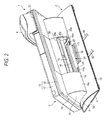
- Fig. 2 is a perspective view showing the telephone according to the embodiment of the invention when viewed from the rear side thereof;
- Fig. 3 is a perspective view showing a base serving as a fixed section in the embodiment of the invention.
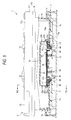
- Fig. 5 is a sectional view showing a position relation of the base and a concave portion and a lock lever of a main body in the embodiment of the invention
- Fig. 6 is an enlarged sectional view showing an F6 part in Fig. 5 ;
- Fig. 7 is a perspective view showing a fixing piece for allowing the lock lever to be rotatably supported by the base in the embodiment of the invention
- Fig. 8 is a perspective view showing the lock lever for keeping the main body at a desired tilt angle in the embodiment of the invention.
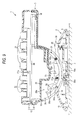
- Fig. 9 is a sectional view showing the telephone taken along Line F9-F9 in Fig. 5 ;
- Fig. 10 is a sectional view showing the telephone in the state where a locking of the main body using the lock lever is released in the embodiment of the invention
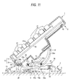
- Fig. 11 is a sectional view showing the telephone in the state where the main body is erected at a desired tilt angle in the embodiment of the invention
- Fig. 12 is a perspective view showing the telephone indicating a wiring path of a cable with respect to the base in the embodiment of the invention.
- Fig. 13 is a sectional view showing the telephone indicating the wiring path of the cable with respect to the base in the embodiment of the invention.
- a tilting mechanism includes: a fixed section including a guide surface depressed in an arc shape; and a movable section having an outer peripheral surface curved in an arc shape that comes in contact with the guide surface of the fixed section and tilting along the guide surface, the movable section including a concave portion cut out to open the outer peripheral surface, wherein: the concave portion includes: a pair of side surfaces opposed to each other; and guide grooves that are curved along a curvature of the outer peripheral surface of the movable section and are formed on the side surfaces; and the fixed section includes a plurality of shafts that are slidably fitted into the guide grooves.
- a tilting mechanism includes: a fixed section including: a pair of guide surfaces depressed in an arc shape; and a plurality of shafts positioned between the guide surfaces; a movable section including: an outer peripheral surface curved in an arc shape that comes in contact with the guide surfaces of the fixed section; a concave portion that is cut out to open the outer peripheral surface and has a pair of side surfaces opposed to each other; guide grooves that are formed on the side surfaces of the concave portion and curved along a curvature of the outer peripheral surface of the movable section and that allow the shafts to be slidably fitted thereto; and a plurality of engagement portions that are formed on the side surfaces of the concave portion and disposed at a predetermined interval in a longitudinal direction of the guide grooves; and a lock member that is supported by the fixed section and revolvable between an engagement position at which the lock member selectively engages with the engagement portion and a disengagement position at which the lock member is disengage
- an electronic apparatus includes: a base including: a pair of guide surfaces depressed in an arc shape; and a plurality of shafts positioned between the guide surfaces; a main body including: an outer peripheral surface curved in an arc shape that comes in contact with the guide surfaces of the base; a concave portion cut out to open the outer peripheral surface and includes a pair of side surfaces opposed to each other; guide grooves that are formed on the side surfaces of the concave portion and curved along a curvature of the outer peripheral surface of the main body and that allow the shafts to be slidably fitted thereto; and a plurality of engagement portions that are formed on the side surfaces of the concave portion and disposed at a predetermined interval in a longitudinal direction of the guide grooves; and a lock member that is supported by the base and revolvable between an engagement position at which the lock member selectively engages with the engagement portion and a disengagement position at which the lock member is disengaged from the engagement portion.
- the telephone 1 includes a base 2, a main body 3 of the apparatus, and a handset 4.
- the base 2 is an example of a fixed section disposed on the desk and includes a bottom plate 5 and a top cover 6.
- the bottom plate 5 is rectangular in shape. As shown in Fig. 3 , a pair of guide surfaces 7a and 7b and a convex portion 8 are formed on the upper surface of the bottom plate 5.
- the guide surfaces 7a and 7b are positioned on the left and right ends of the base 2, respectively, and are curved in an arc shape so as to be concaved.
- the convex portion 8 that protrudes upward from the bottom plate 5 is positioned between the guide surfaces 7a and 7b.
- the convex portion 8 includes left and right side-walls 9a and 9b and an upright wall 10.
- the side-walls 9a and 9b is spaced in the width direction of the base 2 and extends in the depth direction of the base 2.
- the upright wall 10 extends in the width direction of the base 2 so as to be suspended between the rear ends of the side-walls 9a and 9b.
- a through-hole 11 is formed on an area surrounded by the side-walls 9a and 9b and the upright wall 10 in the bottom plate 5.
- the top cover 6 includes an upper wall 13 for covering the upper part of the bottom plate 5.
- the upper wall 13 is curved in an arc shape so as to be convexed upward.
- An opening 14 is formed at the center portion of the upper wall 13.
- the opening 14 has a rectangular opening shape which extends in the width direction of the base 2 and the guide surfaces 7a and 7b and the convex portion 8 are positioned inside the opening 14.
- the main body 3 is an example of a movable section and is tiltably supported by the base 2 within a predetermined angle.
- the main body 3 includes a box-shaped housing 15.
- the housing 15 includes a bottom case 16 and a top cover 17.
- the bottom case 16 includes a rectangular bottom plate 18 and a leg section 19 protruding downward from the bottom plate 18.
- the leg section 19 is formed in a semi-cylindrical shape so as to extend in the width direction of the main body 3. For this reason, the leg section 19 includes an outer peripheral surface 19a which is curved in an arc shape. A curvature of the outer peripheral surface 19a of the leg section 19 corresponds to that of the guide surfaces 7a and 7b of the base 2.
- the top cover 17 is formed in a rectangular flat box-like shape which is opened toward the bottom case 16.
- the top cover 17 is connected to the outer periphery edge of the bottom plate 18 of the bottom case 16 and covers the upper part of the bottom case 16.
- the top cover 17 includes a flat upper surface 17a.
- a plurality of dial buttons 21, a plurality of fixed function buttons 22, and a plurality of free assign button 23 are disposed on the upper surface 17a of the top cover 17.
- an LCD display portion 24 is disposed on the upper surface of the top cover 17.
- the LCD display portion 24 indicates a telephone number, a calendar, a time, a calling/receiving state, and contents that are individually set in the free assign button 23.
- a handset placing portion 25 is formed on the left end portion of the upper surface 17a of the top cover 17.
- the handset 4 is disposed on the handset placing portion 25.
- the main body 3 is configured to be tiltable along the guide surfaces 7a and 7b.
- the leg section 19 of the main body 3 includes a concave portion 28 in which the outer peripheral surface 19a is cut out for an opening.
- the concave portion 28 is disposed on the center portion in the longitudinal direction of the leg section 19 and the convex portion 8 of the base 2 is placed inside the concave portion 28.
- the concave portion 28 includes a pair of left and right side surfaces 29a and 29b and a ceiling surface 30.
- the side surfaces 29a and 29b are opposed to each other in the width direction of the main body 3.
- One side surface 29a of the concave portion 28 is adjacent to one side surface 9a of the convex portion 8 and the other side surface 29b of the concave portion 28 is adjacent to the other side surface 9b of the convex portion 8.
- the ceiling surface 30 is suspended between the side surfaces 29a and 29b so as to face the opening 14 of the base 2.
- the main body 3 is tiltably supported by the base 2 with a tilting mechanism 32 interposed therebetween.
- the tilting mechanism 32 includes a pair of guide grooves 33a and 33b, a pair of shafts 34a and 34b, and a lock lever 35.
- the guide grooves 33a and 33b are formed on the side surfaces 29a and 29b of the concave portion 28, respectively, and exposed in the concave portion 28.
- the guide grooves 33a and 33b are curved in an arc shape so as to follow the guide surfaces 7a and 7b of the base 2.
- Cutouts 36a and 36b are formed on a corner portion formed by the outer peripheral surface 19a of the leg section 19 and the side surfaces 29a and 29b of the concave portion 28, respectively.
- the cutouts 36a and 36b are opened at the position slightly apart from the summit of the outer peripheral surface 19a of the leg section 19 and connect the outer peripheral surface 19a to the guide grooves 33a and 33b.
- five engagement portions 38 are formed on each of the side surfaces 29a and 29b of the concave portion 28.
- the engagement portions 38 are positioned above each of the guide grooves 33a and 33b.
- the engagement portions 38 include cutouts which are opened to the upper side of the guide grooves 33a and 33b and are arranged at a predetermined interval so as to follow the groove direction of the guide grooves 33a and 33b.
- the engagement portions 38 are arranged at a pitch of 10° in the curved direction of the guide grooves 33a and 33b so as to adjust the tilt angle of the main body 3 through, for example, five steps every 10°.
- the front edge 38a positioned on the front side of the main body 3 among the engagement portions 38 is inclined to the front side of the main body 3 in the direction from the bottom of the engagement portion 38 to the opening end thereof.
- the lock lever 35 is an example of a lock member for keeping the main body 3 at a desired tilt angle. As shown in Fig. 2 , the lock lever 35 is received in the opening 14 of the base 2 so as to be positioned between the side surfaces 29a and 29b of the concave portion 28.
- the lock lever 35 includes a base portion 39 and a pair of arm portions 40a and 40b.
- the base portion 39 is formed in a thin and long plate shape which is suspended between the side surfaces 29a and 29b of the concave portion 28 and positioned on the rear end portion of the opening 14.
- the base portion 39 includes a push button 41 on which users of the telephone 1 pushes with their hands. The push button 41 protrudes from the base portion 39 toward the rear side of the opening 14 and exposed on the upper surface of the top cover 6 of the base 2.
- Guide shafts 42a and 42b are formed on both ends in the longitudinal direction of the base portion 39.
- the guide shafts 42a and 42b horizontally protrudes from the both ends of the base portion 39 toward the side surfaces 29a and 29b of the concave portion 28 and disposed on the same axis.
- the guide shafts 42a and 42b are guided from the cutouts 36a and 36b to the guide grooves 33a and 33b so as to be slidably fitted into the guide grooves 33a and 33b.
- the guide shaft 42a of the lock lever 35 and the shaft 34a of the base 2 are spaced from the guide shaft 42b of the lock lever 35 and the shaft 34b of the base 2 in the groove direction of the guide grooves 33a and 33b, respectively.
- a pair of fitting holes 44a and 44b are formed through the base portion 39 of the lock lever 35.
- One fitting hole 44a is adjacent to one guide shaft 42a.
- the other fitting hole 44b is adjacent to the other guide shaft 42b.
- a guide surface 45 is formed inside each of the fitting holes 44a and 44b.
- the guide surface 45 is formed in an arc shape so as to be on the same axis along with the guide shafts 42a and 42b.
- a fixing piece 46 shown in Fig. 7 is each fitted into the inside of the fitting holes 44a and 44b.
- a protrusion portion 47 protruding from the guide surface 45 is formed on one end of the fixing piece 46.
- the protrusion portion 47 includes an outer peripheral surface 47a opposed to the guide surface 45.
- the outer peripheral surface 47a is curved in an arc shape so as to correspond to the curvature of the guide surface 45.
- the outer peripheral surface 47a of the fixing piece 46 is slidably pressed on the guide surface 45 of the lock lever 35.
- the lock lever 35 is rotatably supported by the bottom plate 5 of the base 2 using the outer peripheral surface 47a of the fixing piece 46 as a guide surface.
- the center of the rotation of the lock lever 35 is positioned at the rotation center line O1 of the guide shafts 42a and 42b.
- Claws 51a and 51b are formed on the front ends of the arm portions 40a and 40b.
- the claws 51a and 51b are configured to selectively engage with any one of the engagement portions 38 of the base 2.
- the front surfaces of the claws 51a and 51b are inclined so as to follow the front edge 38a of the engagement portion 38.
- the lock lever 35 is rotatably supported by the base 2 between an engagement position in which the claws 51a and 51b are hung on one of the engagement portions 38 of the base 2 and an engagement releasing position in which the claws 51a and 51b are upwardly detached from the engagement portion 38.
- a pair of compressed springs 52 are interposed between the push button 41 of the lock lever 35 and the bottom plate 5 of the base 2.
- the compressed coil spring 52 is an example of an elastic member and allows the lock lever 35 to be normally urged toward the engaging position. Accordingly, the claws 51a and 51b of the lock lever 35 engage with any one of the engagement portions 38.
- a print circuit board 54 is contained in the housing 15 of the main body 3.
- the print circuit board 54 is disposed in a direction horizontal to the upper surface 17a of the top cover 17.
- First to fourth modular jacks 55, 56, 57, and 58 and a single connector 59 are mounted on the lower surface of the front end portion of the print circuit board 54 (see Fig. 12 ).
- the first to fourth modular jacks 55, 56, 57, and 58 and the single connector 59 are arranged in a row in the width direction of the main body 3, and exposed on the ceiling surface 30 of the concave portion 28.
- the connector 59 is disposed between the second modular jack 56 and the third modular jack 57.
- the first modular jack 55 is provided for being connected to an add-on module connection cable 61.
- the second modular jack 56 is provided for being connected to a telephone line connection cable 62.
- the third modular jack 57 is provided for being connected to a head set connection cable (not shown), and Fig. 12 shows that the head set connection cable is separated from the third modular jack 57.
- the fourth modular jack 58 is provided for being connected to a hand set connection cable 63.
- the connector 59 is provided for being connected to an external speaker connection cable 64.
- the cables 61, 62, and 63 connected to the modular jacks 55, 56, and 58 and the cable 64 connected to the connector 59 are drawn from the ceiling surface 30 of the concave portion 28 to the inside of the concave portion 28 and drawn to the opposite surface of the bottom plate 5 of the base 2 via the through-hole 11.
- First to fourth wiring grooves 65, 66, 67, and 68 are formed on the opposite surface of the bottom plate 5 of the base 2.
- the first wiring groove 65 extends from the opening end of the through-hole 11 to the right edge of the bottom plate 5.
- the second and third wiring grooves 66 and 67 extends from the opening end of the through-hole 11 to the rear edge of the bottom plate 5 and disposed in parallel each other while being apart from each other in the width direction of the base 2.
- the fourth wiring groove 68 extends from the opening end of the through-hole 11 to the left edge of the bottom plate 5.
- a plurality of clamps 69 are formed on the opening edge of the first to fourth wiring grooves 65 to 68.
- the clamps 69 holds the cables 61 to 64 in the first to fourth wiring grooves 65 to 68.
- the upright wall 10 protruding from the bottom plate 5 of the base 2 is positioned in rear of the cables 61 to 64.
- the upper end of the upright wall 10 slightly protrudes from the opening 14 of the upper wall 13 of the base 2.
- a swelling portion 70 protruding downward is formed on the ceiling surface 30 of the concave portion 28 opposed to the upper wall 13 of the base 2.
- the swelling portion 70 is positioned in the rear of the cables 61 to 64.
- the lower end of the swelling portion 70 is adjacent to the upper end of the upright wall 10, and a small gap 71 for allowing the tilting of the main body 3 is formed between the lower end of the swelling portion 70 and the upper end of the upright wall 10.
- the upright wall 10 and the swelling portion 70 together cover the cables 61 to 64 passing through the concave portion 28 from the rear side of the telephone 1. Accordingly, even when the rear side of the ceiling surface 30 of the concave portion 28 is inclinedly lifted and the opening 14 of the base 2 is thereby largely opened to the rear side of the telephone 1 in the same case, as the main body 3 is tilted upward, the cables 61 to 64 are hardly seen from the rear side of the telephone 1.
- Fig. 9 shows that the main body 3 is in a horizontal posture, that is, the tilt angle is 0°.
- the claws 51a and 51b of the lock lever 35 engage with the second engagement portions 38 among the five engagement portions 38 formed on the side surfaces 29a and 29b of the concave portion 28.
- the push button 41 of the first lock lever 35 is pressed in arrow A direction in Fig. 10 by using a fingertip. In this way, the lock lever 35 rotates upward about the guide shafts 42a and 42b from the engagement position to the engagement releasing position, and the claws 51a and 51b of the lock lever 35 are separated from the second engagement portion 38.
- the fixed angle of the main body 3 is released and the main body 3 may be tilted at any angle along the guide grooves 33a and 33b of the main body 3 as long as the push button 41 of the lock lever 35 is pressed.
- the lock lever 35 rotates from the engagement releasing position to the engagement position due to an urging force of the compressed coil spring 52.
- the claws 51a and 51b of the lock lever 35 elastically engage with the fifth engagement portion 38.
- the main body 3 is maintained at the tilt angle of 40°.
- the concave portion 28 is formed on the leg section 19 of the main body 3 that is inserted through the opening 14 of the base 2 in such a manner that the outer peripheral surface 19a is cut out to be opened.
- the guide grooves 33a and 33b for guiding the tilting operation of the main body 3 are formed on the side surfaces 29a and 29b of the concave portion 28.
- the shafts 34a and 34b protruding toward the side surfaces 29a and 29b are formed inside of the opening 14 of the base 2, and the shafts 34a and 34b are allowed to be slidably fitted into the guide grooves 33a and 33b inside the concave portion 28.
- the guide grooves 33a and 33b for guiding the tilting operation of the main body 3 along with the shafts 34a and 34b are configured to be normally stopped inside the concave portion 28 even when the tilt angle of the main body 3 varies. Accordingly, the guide grooves 33a and 33b or the shafts 34a and 34b are not directly exposed on the base 2. In addition, the guide grooves 33a and 33b or the shafts 34a and 34b are hardly seen from the outside of the telephone 1.
- a plurality of engagement portions 38 engaging with the claws 51a and 51b or the lock lever 35 are formed the side surfaces 29a and 29b of the concave portion 28 so as to be adjacent to the guide grooves 33a and 33b.
- the engagement portion 38 is configured to be normally stopped inside the concave portion 28 even when the tilt angle of the main body 3 varies. Accordingly, the engagement portion 38 or the claws 51a and 51b are not directly exposed on the base 2, and the engagement portion 38 or the claws 51a and 51b are hardly seen from the outside of the telephone 1.
- the various cables 61 to 64 that pass through the inside of the concave portion 28 and are drawn by the first to fourth wiring grooves 65 to 68 in rear of the base 2 are covered from the rear side of the telephone 1 by the upright wall 10 protruding upward from the bottom plate 5 of the base 2 and the swelling portion 70 protruding from the ceiling surface 30 of the concave portion 28. For this reason, as shown in Fig.
- the appearance of the telephone 1 becomes good when viewed from the rear side of the telephone 1, which effectively contributes to improving the value of commodities of the telephone 1.
- the shaft 34a of the base 2 and the guide shaft 42a of the lock lever 35 are slidably fitted into the guide groove 33a of one side surface 29a of the concave portion 28, and the shaft 34a and the guide shaft 42a are spaced to each other in the groove direction of the guide groove 33a.
- the shaft 34b of the base 2 and the guide shaft 42b of the lock lever 35 are slidably fitted into the guide groove 33b of the other side surface 29b of the concave portion 28, and the shaft 34b and the guide shaft 42b are spaced from each other in the groove direction of the guide groove 33b.
- the side surfaces 29a and 29b of the concave portion 28 of the main body 3 are supported by the base 2 at two positions which are spaced from each other in the groove direction of the guide grooves 33a and 33b. For this reason, when the main body 3 is tilted along the guide grooves 33a and 33b, the main body 3 is hardly inclined with respect to the axis line of the shafts 34a and 34b or the guide shafts 42a and 42b.
- the main body 3 is allowed to be smoothly tilted along the guide grooves 33a and 33b, thereby easily adjusting the angle of the main body 3.
- the front edge 38a of the engagement portion 38 and the front surface of the claws 51a and 51b are inclined toward the front side of the telephone 1. For this reason, when the interlocked part of the engagement 38 and the claws 51a and 51b are overloaded due to the case where the main body 3 is tilted upward without pressing the push button 41 of the lock lever 35 by mistakes, a force for upwardly pressing the claws 51a and 51b is applied to the arm portions 40a and 40b of the lock lever 35.
- the lock lever 35 rotates in a clockwise, as shown in Fig. 9 , about the guide shafts 42a and 42b, and the claws 51a and 51b separate from the engagement portion 38. Accordingly, it is possible to prevent the engagement 38 and the claws 51a and 51b from being damaged.
- the electronic apparatus having the tilting mechanism according to the invention is not limited the telephone described in the embodiment, but the invention may be also applied to other electronic apparatus such as an information terminal apparatus or a portable display apparatus.
Landscapes
- Engineering & Computer Science (AREA)
- General Engineering & Computer Science (AREA)
- Mechanical Engineering (AREA)
- Signal Processing (AREA)
- Telephone Set Structure (AREA)
Abstract
According to one embodiment, a tilting mechanism includes: a fixed section (2) including a guide surface (7a,7b) depressed in an arc shape; and a movable section (19) having an outer peripheral surface (19a) curved in an arc shape that comes in contact with the guide surface (7a,7b) of the fixed section (2) and tilting along the guide surface (7a,7b), the movable section (19) including a concave portion cut out to open the outer peripheral surface (19a), wherein: the concave portion includes: a pair of side surfaces (29a,29b) opposed to each other; and guide grooves (33a,33b) that are curved along a curvature of the outer peripheral surface (19a) of the movable section (19) and are formed on the side surfaces; and the fixed section (2) includes a plurality of shafts (34a,34b) that are slidably fitted into the guide grooves (33a,33b).
Description
- One embodiment of the invention relates to a tilting mechanism for varying a tilt angle of a movable section with respect to a fixed section. In addition, another embodiment of the invention relates to an electronic apparatus such as a telephone in which a main body having a hand set and a display unit on a base thereof is tiltably attached, and more particularly, to a structure for varying a tilt angle of the main body with respect to the base.
- In an electronic apparatus such as a television-incorporated telephone set disclosed in
JP-A-10-150485 - The communication block generally contains a circuit component for a telephone communication and various operation buttons related to a telephone communication function are arranged on a front surface of the communication block. The display block generally contains a circuit component for a television or a CRT display and a display screen of the CRT display is exposed on a front surface of the display block.
- In such an electronic apparatus, the display block can be tilted with respect to the communication block so that users can adjust a display screen at their disposal.
- Specifically, the upper surface of the communication block is curved in an arc shape so as to be concaved, and a roller is rotatably supported by four corners of the curved part. On the other hand, the lower surface of the display block forms a sliding surface that is curved in an arc shape to protrude, and the roller rotatably comes in contact with the sliding surface. For this reason, the display block is configured to be tilted with respect to the communication block as the arc-shaped sliding surface is slided on the roller.
- In addition, according to
JP-A-10-150485 - The concave portions are arranged in a row at a predetermined interval in the tilting direction of the display block. The locking piece is elastic and a convex portion positioned on the front end thereof selectively engages with the concave portions of the display block. With such a configuration, the display block is maintained at any tilt angle so that the display screen faces a desired direction.
- According to the electronic apparatus disclosed in
JP-A-10-150485 - When a tiltable angle of the display block is increased, the roller positioned on the upper surface of the communication block may be directly exposed to the outside of the communication block in association with the tilting displacement of the display block.
- Since the upper surface of the communication block is easily seen in consideration of a place, the roller may give an uneasiness to users, thereby having a bad influence on the appearance of the electronic apparatus.
- An object of the present invention is to provide a tilting mechanism having a good appearance by hiding a configuration component for guiding a tilting operation of the movable section from the outside of the movable section or the fixed section.
- Another object of the present invention is to provide an electronic apparatus having a good appearance by hiding a configuration component for guiding the tilting operation of a main body and a configuration component for maintaining the main body at a desired tilt angle from the outside of the electronic apparatus.
- According to an aspect of the present invention, there is provided a tilting mechanism including: a fixed section including a guide surface depressed in an arc shape; and a plurality of shafts; and a movable section having an outer peripheral surface curved in an arc shape that comes in contact with the guide surface of the fixed section and tilting along the guide surface, the movable section including a concave portion cut out to open the outer peripheral surface, wherein: the concave portion includes: a pair of side surfaces opposed to each other; and guide grooves that are curved along a curvature of the outer peripheral surface of the movable section and are formed on the side surfaces; and the plurality of shafts are slidably fitted into the guide grooves.
- The fixed section may include an opening which the outer peripheral surface of the movable section is entered. The guide surface and the shaft may be positioned inside the opening.
- The movable section may include a plurality of cutouts that guide the shafts of the fixed section to the guide grooves. The cutouts may open the outer peripheral surface of the movable section.
- According to another aspect of the present invention, there is provided a tilting mechanism including: a fixed section including: a pair of guide surfaces depressed in an arc shape; and a plurality of shafts positioned between the guide surfaces; a movable section including: an outer peripheral surface curved in an arc shape that comes in contact with the guide surfaces of the fixed section; a concave portion that is cut out to open the outer peripheral surface and has a pair of side surfaces opposed to each other; guide grooves that are formed on the side surfaces of the concave portion and curved along a curvature of the outer peripheral surface of the movable section and that allow the shafts to be slidably fitted thereto; and a plurality of engagement portions that are formed on the side surfaces of the concave portion and disposed at a predetermined interval in a longitudinal direction of the guide grooves; and a lock member that is supported by the fixed section and revolvable between an engagement position at which the lock member selectively engages with the engagement portion and a disengagement position at which the lock member is disengaged from the engagement portion.
- The lock member may include a pair of guide shafts. The guide shafts may be slidably fitted into the guide grooves at a position spaced from the shafts of the fixed section in a longitudinal direction of the guide grooves. A revolution center of the lock member may be positioned on a center line of the guide shafts.
- The lock member may include: a base portion including a push button to be manually operated; and a pair of arm portions protruding from the base portion; a pair of guide shafts that are slidably fitted into the guide grooves are formed on the base portion; and claws that selectively engage with the engagement portions on the side surfaces of the fixed section are formed on the arm portions.
- The guide shafts may be slidably fitted into the guide grooves at a position spaced from the shafts of the fixed section in a longitudinal direction of the guide grooves. The revolution center of the lock member may be positioned on the center line of the guide shafts.
- The lock member may be positioned between the side surfaces of the concave portion. A push button of the lock member may be exposed from the concave portion.
- The lock member may be normally urged to the engagement position with an elastic member interposed therebetween.
- According to still another aspect of the present invention, there is provided an electronic apparatus including: a base including: a pair of guide surfaces depressed in an arc shape; and a plurality of shafts positioned between the guide surfaces; a main body including: an outer peripheral surface curved in an arc shape that comes in contact with the guide surfaces of the base; a concave portion cut out to open the outer peripheral surface and includes a pair of side surfaces opposed to each other; guide grooves that are formed on the side surfaces of the concave portion and curved along a curvature of the outer peripheral surface of the main body and that allow the shafts to be slidably fitted thereto; and a plurality of engagement portions that are formed on the side surfaces of the concave portion and disposed at a predetermined interval in a longitudinal direction of the guide grooves; and a lock member that is supported by the base and revolvable between an engagement position at which the lock member selectively engages with the engagement portion and a disengagement position at which the lock member is disengaged from the engagement portion.
- The lock member may include: a base including a push button to be manually operated; and a pair of arm portions protruding from the base; a pair of guide shafts that are slidably fitted into the guide grooves are formed on the base; claws that selectively engage with the engagement portions on the side surfaces of the fixed section are formed on the arm portions. The guide shafts may be slidably fitted into the guide grooves at the position spaced from the shafts of the fixed section in a longitudinal direction of the guide grooves and the revolution center of the lock member may be positioned on the center line of the guide shafts.
- The base may include an opening formed at a position opposed to the concave portion of the main body. The main body may include a connector to which a cable is connected on the front end of the concave portion. The cable may be drawn from an inside of the concave portion to a bottom of the base via the opening.
- The main body may include a convex portion protruding from an inner surface of the concave portion to the opening of the base. The base may include an upright wall protruding from the bottom of the base to the concave portion of the main body. The convex portion and the upright wall may be opposed to each other in rear of the cable.
- A gap that allows a tilt displacement of the main body may be formed between the lower end of the convex portion and the upper end of the upright wall
- A general architecture that implements the various feature of the invention will now be described with reference to the drawings. The drawings and the associated descriptions are provided to illustrate embodiments of the invention and not to limit the scope of the invention.
-
Fig. 1 is a perspective view showing a telephone according to an embodiment of the invention when viewed from the front side thereof; -
Fig. 2 is a perspective view showing the telephone according to the embodiment of the invention when viewed from the rear side thereof; -
Fig. 3 is a perspective view showing a base serving as a fixed section in the embodiment of the invention; -
Fig. 4 is a perspective view showing a bottom case constituting a movable section in the embodiment of the invention; -
Fig. 5 is a sectional view showing a position relation of the base and a concave portion and a lock lever of a main body in the embodiment of the invention; -
Fig. 6 is an enlarged sectional view showing an F6 part inFig. 5 ; -
Fig. 7 is a perspective view showing a fixing piece for allowing the lock lever to be rotatably supported by the base in the embodiment of the invention; -
Fig. 8 is a perspective view showing the lock lever for keeping the main body at a desired tilt angle in the embodiment of the invention; -
Fig. 9 is a sectional view showing the telephone taken along Line F9-F9 inFig. 5 ; -
Fig. 10 is a sectional view showing the telephone in the state where a locking of the main body using the lock lever is released in the embodiment of the invention; -
Fig. 11 is a sectional view showing the telephone in the state where the main body is erected at a desired tilt angle in the embodiment of the invention; -
Fig. 12 is a perspective view showing the telephone indicating a wiring path of a cable with respect to the base in the embodiment of the invention; and -
Fig. 13 is a sectional view showing the telephone indicating the wiring path of the cable with respect to the base in the embodiment of the invention. - Various embodiments according to the invention will be described hereinafter with reference to the accompanying drawings. In general, according to one embodiment of the invention, a tilting mechanism includes: a fixed section including a guide surface depressed in an arc shape; and a movable section having an outer peripheral surface curved in an arc shape that comes in contact with the guide surface of the fixed section and tilting along the guide surface, the movable section including a concave portion cut out to open the outer peripheral surface, wherein: the concave portion includes: a pair of side surfaces opposed to each other; and guide grooves that are curved along a curvature of the outer peripheral surface of the movable section and are formed on the side surfaces; and the fixed section includes a plurality of shafts that are slidably fitted into the guide grooves. Further, according to another embodiment of the invention, a tilting mechanism includes: a fixed section including: a pair of guide surfaces depressed in an arc shape; and a plurality of shafts positioned between the guide surfaces; a movable section including: an outer peripheral surface curved in an arc shape that comes in contact with the guide surfaces of the fixed section; a concave portion that is cut out to open the outer peripheral surface and has a pair of side surfaces opposed to each other; guide grooves that are formed on the side surfaces of the concave portion and curved along a curvature of the outer peripheral surface of the movable section and that allow the shafts to be slidably fitted thereto; and a plurality of engagement portions that are formed on the side surfaces of the concave portion and disposed at a predetermined interval in a longitudinal direction of the guide grooves; and a lock member that is supported by the fixed section and revolvable between an engagement position at which the lock member selectively engages with the engagement portion and a disengagement position at which the lock member is disengaged from the engagement portion. Further, according to another embodiment of the invention, an electronic apparatus includes: a base including: a pair of guide surfaces depressed in an arc shape; and a plurality of shafts positioned between the guide surfaces; a main body including: an outer peripheral surface curved in an arc shape that comes in contact with the guide surfaces of the base; a concave portion cut out to open the outer peripheral surface and includes a pair of side surfaces opposed to each other; guide grooves that are formed on the side surfaces of the concave portion and curved along a curvature of the outer peripheral surface of the main body and that allow the shafts to be slidably fitted thereto; and a plurality of engagement portions that are formed on the side surfaces of the concave portion and disposed at a predetermined interval in a longitudinal direction of the guide grooves; and a lock member that is supported by the base and revolvable between an engagement position at which the lock member selectively engages with the engagement portion and a disengagement position at which the lock member is disengaged from the engagement portion.
- Hereinafter, an embodiment of the invention will be described with reference to
Figs. 1 to 13 . -
Figs. 1 and2 show a telephone 1 as an example of an electronic apparatus. The telephone 1 related to the embodiment can be used for a general usage in an office or a household. For example, the telephone 1 may be used while being placed on a desk or hung on a wall. - The telephone 1 includes a
base 2, amain body 3 of the apparatus, and ahandset 4. For example, thebase 2 is an example of a fixed section disposed on the desk and includes abottom plate 5 and atop cover 6. - The
bottom plate 5 is rectangular in shape. As shown inFig. 3 , a pair ofguide surfaces convex portion 8 are formed on the upper surface of thebottom plate 5. The guide surfaces 7a and 7b are positioned on the left and right ends of thebase 2, respectively, and are curved in an arc shape so as to be concaved. - The
convex portion 8 that protrudes upward from thebottom plate 5 is positioned between the guide surfaces 7a and 7b. Theconvex portion 8 includes left and right side-walls upright wall 10. The side-walls base 2 and extends in the depth direction of thebase 2. Theupright wall 10 extends in the width direction of thebase 2 so as to be suspended between the rear ends of the side-walls hole 11 is formed on an area surrounded by the side-walls upright wall 10 in thebottom plate 5. - The
top cover 6 includes anupper wall 13 for covering the upper part of thebottom plate 5. Theupper wall 13 is curved in an arc shape so as to be convexed upward. Anopening 14 is formed at the center portion of theupper wall 13. Theopening 14 has a rectangular opening shape which extends in the width direction of thebase 2 and the guide surfaces 7a and 7b and theconvex portion 8 are positioned inside theopening 14. - The
main body 3 is an example of a movable section and is tiltably supported by thebase 2 within a predetermined angle. Themain body 3 includes a box-shapedhousing 15. Thehousing 15 includes abottom case 16 and atop cover 17. - The
bottom case 16 includes arectangular bottom plate 18 and aleg section 19 protruding downward from thebottom plate 18. Theleg section 19 is formed in a semi-cylindrical shape so as to extend in the width direction of themain body 3. For this reason, theleg section 19 includes an outerperipheral surface 19a which is curved in an arc shape. A curvature of the outerperipheral surface 19a of theleg section 19 corresponds to that of the guide surfaces 7a and 7b of thebase 2. - The
top cover 17 is formed in a rectangular flat box-like shape which is opened toward thebottom case 16. Thetop cover 17 is connected to the outer periphery edge of thebottom plate 18 of thebottom case 16 and covers the upper part of thebottom case 16. - The
top cover 17 includes a flatupper surface 17a. A plurality ofdial buttons 21, a plurality of fixedfunction buttons 22, and a plurality of free assignbutton 23 are disposed on theupper surface 17a of thetop cover 17. In addition, anLCD display portion 24 is disposed on the upper surface of thetop cover 17. For example, theLCD display portion 24 indicates a telephone number, a calendar, a time, a calling/receiving state, and contents that are individually set in the free assignbutton 23. - A
handset placing portion 25 is formed on the left end portion of theupper surface 17a of thetop cover 17. Thehandset 4 is disposed on thehandset placing portion 25. - As shown in
Fig. 5 , in theleg section 19 of themain body 3, a part of the outerperipheral surface 19a is inserted in theopening 14 of thebase 2. A part of the outerperipheral surface 19a of theleg section 19 comes in sliding-contact with the guide surfaces 7a and 7b of thebase 2. For this reason, themain body 3 is configured to be tiltable along the guide surfaces 7a and 7b. - As shown in
Figs. 2 ,4 , and5 , theleg section 19 of themain body 3 includes aconcave portion 28 in which the outerperipheral surface 19a is cut out for an opening. Theconcave portion 28 is disposed on the center portion in the longitudinal direction of theleg section 19 and theconvex portion 8 of thebase 2 is placed inside theconcave portion 28. - The
concave portion 28 includes a pair of left and right side surfaces 29a and 29b and aceiling surface 30. The side surfaces 29a and 29b are opposed to each other in the width direction of themain body 3. Oneside surface 29a of theconcave portion 28 is adjacent to oneside surface 9a of theconvex portion 8 and theother side surface 29b of theconcave portion 28 is adjacent to theother side surface 9b of theconvex portion 8. Theceiling surface 30 is suspended between the side surfaces 29a and 29b so as to face theopening 14 of thebase 2. - As shown in
Fig. 5 ,9 , and11 , themain body 3 is tiltably supported by thebase 2 with atilting mechanism 32 interposed therebetween. Thetilting mechanism 32 includes a pair ofguide grooves shafts lock lever 35. - The
guide grooves concave portion 28, respectively, and exposed in theconcave portion 28. Theguide grooves base 2.Cutouts peripheral surface 19a of theleg section 19 and the side surfaces 29a and 29b of theconcave portion 28, respectively. Thecutouts peripheral surface 19a of theleg section 19 and connect the outerperipheral surface 19a to theguide grooves - The
shafts base 2 horizontally protrude from the side surfaces 9a and 9b of theconvex portion 8 to the side surfaces 29a and 29b of theconcave portion 28 so as to be disposed on the same shaft. Theshafts guide grooves cutouts guide grooves main body 3 is configured to be tiltable along theguide grooves - As shown in
Fig. 4 and9 , fiveengagement portions 38 are formed on each of the side surfaces 29a and 29b of theconcave portion 28. Theengagement portions 38 are positioned above each of theguide grooves engagement portions 38 include cutouts which are opened to the upper side of theguide grooves guide grooves engagement portions 38 are arranged at a pitch of 10° in the curved direction of theguide grooves main body 3 through, for example, five steps every 10°. - In addition, according to the embodiment, the
front edge 38a positioned on the front side of themain body 3 among theengagement portions 38 is inclined to the front side of themain body 3 in the direction from the bottom of theengagement portion 38 to the opening end thereof. - The
lock lever 35 is an example of a lock member for keeping themain body 3 at a desired tilt angle. As shown inFig. 2 , thelock lever 35 is received in theopening 14 of thebase 2 so as to be positioned between the side surfaces 29a and 29b of theconcave portion 28. - As shown in
Fig. 8 , thelock lever 35 includes abase portion 39 and a pair ofarm portions base portion 39 is formed in a thin and long plate shape which is suspended between the side surfaces 29a and 29b of theconcave portion 28 and positioned on the rear end portion of theopening 14. Thebase portion 39 includes apush button 41 on which users of the telephone 1 pushes with their hands. Thepush button 41 protrudes from thebase portion 39 toward the rear side of theopening 14 and exposed on the upper surface of thetop cover 6 of thebase 2. -
Guide shafts base portion 39. Theguide shafts base portion 39 toward the side surfaces 29a and 29b of theconcave portion 28 and disposed on the same axis. Theguide shafts cutouts guide grooves guide grooves guide shaft 42a of thelock lever 35 and theshaft 34a of thebase 2 are spaced from theguide shaft 42b of thelock lever 35 and theshaft 34b of thebase 2 in the groove direction of theguide grooves - As shown in
Figs. 5 ,6 , and8 , a pair offitting holes base portion 39 of thelock lever 35. Onefitting hole 44a is adjacent to oneguide shaft 42a. The otherfitting hole 44b is adjacent to theother guide shaft 42b. Aguide surface 45 is formed inside each of thefitting holes guide surface 45 is formed in an arc shape so as to be on the same axis along with theguide shafts - A fixing
piece 46 shown inFig. 7 is each fitted into the inside of thefitting holes protrusion portion 47 protruding from theguide surface 45 is formed on one end of the fixingpiece 46. Theprotrusion portion 47 includes an outerperipheral surface 47a opposed to theguide surface 45. The outerperipheral surface 47a is curved in an arc shape so as to correspond to the curvature of theguide surface 45. - The lower ends of the fixing
pieces 46 fitted into thefitting holes attachment sheet 48 formed on thelower plate 5 of thebase 2 through thefitting holes piece 46 is fixed to theattachment sheet 48 by abolt 49. - With such a fixing operation, the outer
peripheral surface 47a of the fixingpiece 46 is slidably pressed on theguide surface 45 of thelock lever 35. For this reason, thelock lever 35 is rotatably supported by thebottom plate 5 of thebase 2 using the outerperipheral surface 47a of the fixingpiece 46 as a guide surface. The center of the rotation of thelock lever 35 is positioned at the rotation center line O1 of theguide shafts - One
arm portion 40a of thelock lever 35 extends from one end of thebase portion 39 toward the opposite side of thepush button 41 and is adjacent to the oneside surface 29a of theconcave portion 28. Similarly, theother arm portion 40b of thelock lever 35 extends from the other end of thebase portion 39 toward the opposite side of thepush button 41 and is adjacent to theother side surface 29b of theconcave portion 28. -
Claws arm portions claws engagement portions 38 of thebase 2. The front surfaces of theclaws front edge 38a of theengagement portion 38. - In this way, the
lock lever 35 is rotatably supported by thebase 2 between an engagement position in which theclaws engagement portions 38 of thebase 2 and an engagement releasing position in which theclaws engagement portion 38. - A pair of
compressed springs 52 are interposed between thepush button 41 of thelock lever 35 and thebottom plate 5 of thebase 2. Thecompressed coil spring 52 is an example of an elastic member and allows thelock lever 35 to be normally urged toward the engaging position. Accordingly, theclaws lock lever 35 engage with any one of theengagement portions 38. - As shown in
Figs. 9 and13 , aprint circuit board 54 is contained in thehousing 15 of themain body 3. Theprint circuit board 54 is disposed in a direction horizontal to theupper surface 17a of thetop cover 17. First to fourthmodular jacks single connector 59 are mounted on the lower surface of the front end portion of the print circuit board 54 (seeFig. 12 ). The first to fourthmodular jacks single connector 59 are arranged in a row in the width direction of themain body 3, and exposed on theceiling surface 30 of theconcave portion 28. Theconnector 59 is disposed between the secondmodular jack 56 and the thirdmodular jack 57. - The first
modular jack 55 is provided for being connected to an add-onmodule connection cable 61. The secondmodular jack 56 is provided for being connected to a telephoneline connection cable 62. The thirdmodular jack 57 is provided for being connected to a head set connection cable (not shown), andFig. 12 shows that the head set connection cable is separated from the thirdmodular jack 57. The fourthmodular jack 58 is provided for being connected to a hand setconnection cable 63. In addition, theconnector 59 is provided for being connected to an externalspeaker connection cable 64. - The
cables modular jacks cable 64 connected to theconnector 59 are drawn from theceiling surface 30 of theconcave portion 28 to the inside of theconcave portion 28 and drawn to the opposite surface of thebottom plate 5 of thebase 2 via the through-hole 11. - First to
fourth wiring grooves bottom plate 5 of thebase 2. Thefirst wiring groove 65 extends from the opening end of the through-hole 11 to the right edge of thebottom plate 5. The second andthird wiring grooves hole 11 to the rear edge of thebottom plate 5 and disposed in parallel each other while being apart from each other in the width direction of thebase 2. Thefourth wiring groove 68 extends from the opening end of the through-hole 11 to the left edge of thebottom plate 5. - The add-on
module connection cable 61 is drawn from the through-hole 11 to the right side of thebase 2 via thefirst wiring groove 65. The telephoneline connection cable 62 is drawn from the through-hole 11 to the rear side of thebase 2 via thesecond wiring groove 66. Similarly, the externalspeaker connection cable 64 is drawn from the through-hole 11 to the rear side of thebase 2 via thethird wiring groove 67. The hand setconnection cable 63 is drawn to the left side of thebase 2 via thefourth wiring groove 68 and drawn by thehand set 4. - According to the embodiment, a plurality of
clamps 69 are formed on the opening edge of the first tofourth wiring grooves 65 to 68. The clamps 69 holds thecables 61 to 64 in the first tofourth wiring grooves 65 to 68. - As shown in
Figs. 12 and13 , theupright wall 10 protruding from thebottom plate 5 of thebase 2 is positioned in rear of thecables 61 to 64. The upper end of theupright wall 10 slightly protrudes from theopening 14 of theupper wall 13 of thebase 2. - A swelling
portion 70 protruding downward is formed on theceiling surface 30 of theconcave portion 28 opposed to theupper wall 13 of thebase 2. The swellingportion 70 is positioned in the rear of thecables 61 to 64. The lower end of the swellingportion 70 is adjacent to the upper end of theupright wall 10, and asmall gap 71 for allowing the tilting of themain body 3 is formed between the lower end of the swellingportion 70 and the upper end of theupright wall 10. - For this reason, the
upright wall 10 and the swellingportion 70 together cover thecables 61 to 64 passing through theconcave portion 28 from the rear side of the telephone 1. Accordingly, even when the rear side of theceiling surface 30 of theconcave portion 28 is inclinedly lifted and theopening 14 of thebase 2 is thereby largely opened to the rear side of the telephone 1 in the same case, as themain body 3 is tilted upward, thecables 61 to 64 are hardly seen from the rear side of the telephone 1. - In the telephone 1 having such a configuration, a procedure by which the tilt angle of the
main body 3 varies will be described. -
Fig. 9 shows that themain body 3 is in a horizontal posture, that is, the tilt angle is 0°. When themain body 3 is in the horizontal posture, theclaws lock lever 35 engage with thesecond engagement portions 38 among the fiveengagement portions 38 formed on the side surfaces 29a and 29b of theconcave portion 28. - In order to change the tilt angle of the
main body 3, first thepush button 41 of thefirst lock lever 35 is pressed in arrow A direction inFig. 10 by using a fingertip. In this way, thelock lever 35 rotates upward about theguide shafts claws lock lever 35 are separated from thesecond engagement portion 38. - As a result, the fixed angle of the
main body 3 is released and themain body 3 may be tilted at any angle along theguide grooves main body 3 as long as thepush button 41 of thelock lever 35 is pressed. - For example, when the pressing operation of the
lock lever 35 is released after upwardly rotating themain body 3 from the horizontal posture to 40° by pressing thelock lever 35, thelock lever 35 rotates from the engagement releasing position to the engagement position due to an urging force of thecompressed coil spring 52. With such a rotation, as shown inFig. 11 theclaws lock lever 35 elastically engage with thefifth engagement portion 38. As a result, themain body 3 is maintained at the tilt angle of 40°. - In such a telephone 1, the
concave portion 28 is formed on theleg section 19 of themain body 3 that is inserted through theopening 14 of thebase 2 in such a manner that the outerperipheral surface 19a is cut out to be opened. In addition, theguide grooves main body 3 are formed on the side surfaces 29a and 29b of theconcave portion 28. Further, theshafts opening 14 of thebase 2, and theshafts guide grooves concave portion 28. - For this reason, the
guide grooves main body 3 along with theshafts concave portion 28 even when the tilt angle of themain body 3 varies. Accordingly, theguide grooves shafts base 2. In addition, theguide grooves shafts - Further, a plurality of
engagement portions 38 engaging with theclaws lock lever 35 are formed the side surfaces 29a and 29b of theconcave portion 28 so as to be adjacent to theguide grooves engagement portion 38 is configured to be normally stopped inside theconcave portion 28 even when the tilt angle of themain body 3 varies. Accordingly, theengagement portion 38 or theclaws base 2, and theengagement portion 38 or theclaws - As a result, even when the
main body 3 is maintained at any tilt angle in the range of 0° to 40°, the good appearance of the telephone 1 can be maintained, thereby improving the value of commodities. - In addition, according to the embodiment, the
various cables 61 to 64 that pass through the inside of theconcave portion 28 and are drawn by the first tofourth wiring grooves 65 to 68 in rear of thebase 2 are covered from the rear side of the telephone 1 by theupright wall 10 protruding upward from thebottom plate 5 of thebase 2 and the swellingportion 70 protruding from theceiling surface 30 of theconcave portion 28. For this reason, as shown inFig. 13 , even when the rear portion of theceiling surface 30 of theconcave portion 28 is inclinedly lifted and theconcave portion 28 is thereby largely opened to the rear side of the telephone 1 in the same case, as themain body 3 is tilted upward, thecables 61 to 64 passing through the inside of theconcave portion 28 are hardly seen from the rear side of the telephone 1. - Accordingly, the appearance of the telephone 1 becomes good when viewed from the rear side of the telephone 1, which effectively contributes to improving the value of commodities of the telephone 1.
- In addition, the
shaft 34a of thebase 2 and theguide shaft 42a of thelock lever 35 are slidably fitted into theguide groove 33a of oneside surface 29a of theconcave portion 28, and theshaft 34a and theguide shaft 42a are spaced to each other in the groove direction of theguide groove 33a. Similarly, theshaft 34b of thebase 2 and theguide shaft 42b of thelock lever 35 are slidably fitted into theguide groove 33b of theother side surface 29b of theconcave portion 28, and theshaft 34b and theguide shaft 42b are spaced from each other in the groove direction of theguide groove 33b. - In other words, the side surfaces 29a and 29b of the
concave portion 28 of themain body 3 are supported by thebase 2 at two positions which are spaced from each other in the groove direction of theguide grooves main body 3 is tilted along theguide grooves main body 3 is hardly inclined with respect to the axis line of theshafts guide shafts - As a result, the
main body 3 is allowed to be smoothly tilted along theguide grooves main body 3. - In addition, in the
lock lever 35 according to the embodiment, the outerperipheral surface 47a of the fixingpiece 46 defining the revolution center is positioned between thepush button 41 and theclaws lock lever 35 is tilted like a seesaw by pressing thepush button 41. For this reason, thepush button 41 may be farther apart from the revolution center of thelock lever 35, thereby enabling thepush button 41 to be largely exposed to the rear side of theopening 14 of thebase 2 in the same manner as specifically shown inFig. 2 . - Accordingly, the operability of pressing the
lock lever 35 using a fingertip is improved and the angle of themain body 3 is easily adjusted. - In addition, according to the embodiment, the
front edge 38a of theengagement portion 38 and the front surface of theclaws engagement 38 and theclaws main body 3 is tilted upward without pressing thepush button 41 of thelock lever 35 by mistakes, a force for upwardly pressing theclaws arm portions lock lever 35. - As a result, the
lock lever 35 rotates in a clockwise, as shown inFig. 9 , about theguide shafts claws engagement portion 38. Accordingly, it is possible to prevent theengagement 38 and theclaws - The electronic apparatus having the tilting mechanism according to the invention is not limited the telephone described in the embodiment, but the invention may be also applied to other electronic apparatus such as an information terminal apparatus or a portable display apparatus.
- While certain embodiments of the inventions have been described, these embodiments have been presented by way of example only, and are not intended to limit the scope of the inventions. Indeed, the novel methods and systems described herein may be embodied in a variety of other forms; furthermore, various omissions, substitutions and changes in the form of the methods and systems described herein may be made without departing from the spirit of the inventions. The accompanying claims and their equivalents are intended to cover such forms or modifications as would fall within the scope and spirit of the inventions.
Claims (14)
- A tilting mechanism comprising:a fixed section including a guide surface depressed in an arc shape; and a plurality of shafts; anda movable section having an outer peripheral surface curved in an arc shape that comes in contact with the guide surface of the fixed section and tilting along the guide surface, the movable section including a concave portion cut out to open the outer peripheral surface, wherein:the concave portion includes: a pair of side surfaces opposed to each other; and guide grooves that are curved along a curvature of the outer peripheral surface of the movable section and are formed on the side surfaces; andthe plurality of shafts are slidably fitted into the guide grooves.
- The tilting mechanism according to Claim 1, wherein:the fixed section includes an opening which the outer peripheral surface of the movable section is entered; andthe guide surface and the shaft are positioned inside the opening.
- The tilting mechanism according to Claim 1, wherein:the movable section includes a plurality of cutouts that guide the shafts of the fixed section to the guide grooves; andthe cutouts open the outer peripheral surface of the movable section.
- A tilting mechanism comprising:a fixed section including: a pair of guide surfaces depressed in an arc shape; and a plurality of shafts positioned between the guide surfaces;a movable section including: an outer peripheral surface curved in an arc shape that comes in contact with the guide surfaces of the fixed section; a concave portion that is cut out to open the outer peripheral surface and has a pair of side surfaces opposed to each other; guide grooves that are formed on the side surfaces of the concave portion and curved along a curvature of the outer peripheral surface of the movable section and that allow the shafts to be slidably fitted thereto; and a plurality of engagement portions that are formed on the side surfaces of the concave portion and disposed at a predetermined interval in a longitudinal direction of the guide grooves; anda lock member that is supported by the fixed section and revolvable between an engagement position at which the lock member selectively engages with the engagement portion and a disengagement position at which the lock member is disengaged from the engagement portion.
- The tilting mechanism according to Claim 4, wherein:the lock member includes a pair of guide shafts;the guide shafts are slidably fitted into the guide grooves at a position spaced from the shafts of the fixed section in a longitudinal direction of the guide grooves; anda revolution center of the lock member is positioned on a center line of the guide shafts.
- The tilting mechanism according to Claim 4, wherein:the lock member includes: a base portion including a push button to be manually operated; and a pair of arm portions protruding from the base portion;a pair of guide shafts that are slidably fitted into the guide grooves are formed on the base portion; andclaws that selectively engage with the engagement portions on the side surfaces of the fixed section are formed on the arm portions.
- The tilting mechanism according to Claim 6, wherein:the guide shafts are slidably fitted into the guide grooves at a position spaced from the shafts of the fixed section in a longitudinal direction of the guide grooves; andthe revolution center of the lock member is positioned on the center line of the guide shafts.
- The tilting mechanism according to Claim 6, wherein:the lock member is positioned between the side surfaces of the concave portion; anda push button of the lock member is exposed from the concave portion.
- The tilting mechanism according to Claim 4, wherein
the lock member is normally urged to the engagement position with an elastic member interposed therebetween. - An electronic apparatus comprising:a base including: a pair of guide surfaces depressed in an arc shape; and a plurality of shafts positioned between the guide surfaces;a main body including: an outer peripheral surface curved in an arc shape that comes in contact with the guide surfaces of the base; a concave portion cut out to open the outer peripheral surface and includes a pair of side surfaces opposed to each other; guide grooves that are formed on the side surfaces of the concave portion and curved along a curvature of the outer peripheral surface of the main body and that allow the shafts to be slidably fitted thereto; and a plurality of engagement portions that are formed on the side surfaces of the concave portion and disposed at a predetermined interval in a longitudinal direction of the guide grooves; anda lock member that is supported by the base and revolvable between an engagement position at which the lock member selectively engages with the engagement portion and a disengagement position at which the lock member is disengaged from the engagement portion.
- The electronic apparatus according to Claim 10, wherein:the lock member includes: a base including a push button to be manually operated; and a pair of arm portions protruding from the base;a pair of guide shafts that are slidably fitted into the guide grooves are formed on the base;claws that selectively engage with the engagement portions on the side surfaces of the fixed section are formed on the arm portions; andthe guide shafts are slidably fitted into the guide grooves at the position spaced from the shafts of the fixed section in a longitudinal direction of the guide grooves and the revolution center of the lock member is positioned on the center line of the guide shafts.
- The electronic apparatus according to Claim 10, wherein:the base includes an opening formed at a position opposed to the concave portion of the main body; andthe main body includes a connector to which a cable is connected on the front end of the concave portion and the cable is drawn from an inside of the concave portion to a bottom of the base via the opening.
- The electronic apparatus according to Claim 12, wherein:the main body includes a convex portion protruding from an inner surface of the concave portion to the opening of the base;the base includes an upright wall protruding from the bottom of the base to the concave portion of the main body; andthe convex portion and the upright wall are opposed to each other in rear of the cable.
- The electronic apparatus according to Claim 13, wherein
a gap that allows a tilt displacement of the main body is formed between the lower end of the convex portion and the upper end of the upright wall.
Applications Claiming Priority (1)
| Application Number | Priority Date | Filing Date | Title |
|---|---|---|---|
| JP2007116173A JP4734284B2 (en) | 2007-04-25 | 2007-04-25 | Variable angle mechanism and electronic equipment |
Publications (1)
| Publication Number | Publication Date |
|---|---|
| EP1985910A2 true EP1985910A2 (en) | 2008-10-29 |
Family
ID=39590201
Family Applications (1)
| Application Number | Title | Priority Date | Filing Date |
|---|---|---|---|
| EP08150010A Withdrawn EP1985910A2 (en) | 2007-04-25 | 2008-01-02 | Tilting mechanism and electronic apparatus |
Country Status (5)
| Country | Link |
|---|---|
| US (1) | US8090096B2 (en) |
| EP (1) | EP1985910A2 (en) |
| JP (1) | JP4734284B2 (en) |
| CN (1) | CN101296264A (en) |
| CA (1) | CA2618124A1 (en) |
Cited By (1)
| Publication number | Priority date | Publication date | Assignee | Title |
|---|---|---|---|---|
| GB2455842A (en) * | 2007-12-21 | 2009-06-24 | Toshiba Kk | Angle variable mechanism for desktop apparatus |
Families Citing this family (4)
| Publication number | Priority date | Publication date | Assignee | Title |
|---|---|---|---|---|
| US9239128B2 (en) * | 2011-05-31 | 2016-01-19 | Canon Kabushiki Kaisha | Image forming apapratus |
| JP5718832B2 (en) * | 2012-01-27 | 2015-05-13 | 富士通フロンテック株式会社 | Information processing device |
| JP6347046B2 (en) * | 2014-07-30 | 2018-06-27 | パナソニックIpマネジメント株式会社 | Terminal device |
| JP6773348B1 (en) * | 2019-09-12 | 2020-10-21 | Necプラットフォームズ株式会社 | How to assemble the angle adjustment mechanism, desktop equipment and angle adjustment mechanism |
Citations (1)
| Publication number | Priority date | Publication date | Assignee | Title |
|---|---|---|---|---|
| JPH10150485A (en) | 1996-11-16 | 1998-06-02 | Sony Corp | Television integrated phone |
Family Cites Families (7)
| Publication number | Priority date | Publication date | Assignee | Title |
|---|---|---|---|---|
| JPH0745965A (en) | 1993-07-30 | 1995-02-14 | Sanyo Electric Co Ltd | Tilt angle regulating mechanism for information apparatus |
| GB2330477B (en) * | 1998-01-26 | 1999-09-01 | Mitel Corp | Variable angle mechanism for desktop telephone |
| US6215869B1 (en) * | 1998-11-17 | 2001-04-10 | Sony Corporation | Articulating telephone base |
| JP2003087382A (en) | 2001-01-10 | 2003-03-20 | Toshiba Corp | Variable angle device for electronic equipment |
| CA2366784C (en) * | 2001-01-10 | 2007-03-13 | Kabushiki Kaisha Toshiba | Electronic equipment mounting angle varying apparatus |
| JP2003130036A (en) * | 2001-10-25 | 2003-05-08 | Sharp Corp | Electronics |
| JP2003182464A (en) * | 2001-12-21 | 2003-07-03 | Toyoda Gosei Co Ltd | Vehicle control device |
-
2007
- 2007-04-25 JP JP2007116173A patent/JP4734284B2/en not_active Expired - Fee Related
-
2008
- 2008-01-02 EP EP08150010A patent/EP1985910A2/en not_active Withdrawn
- 2008-01-10 US US11/972,149 patent/US8090096B2/en not_active Expired - Fee Related
- 2008-01-22 CA CA002618124A patent/CA2618124A1/en not_active Abandoned
- 2008-01-23 CN CNA2008100039487A patent/CN101296264A/en active Pending
Patent Citations (1)
| Publication number | Priority date | Publication date | Assignee | Title |
|---|---|---|---|---|
| JPH10150485A (en) | 1996-11-16 | 1998-06-02 | Sony Corp | Television integrated phone |
Cited By (3)
| Publication number | Priority date | Publication date | Assignee | Title |
|---|---|---|---|---|
| GB2455842A (en) * | 2007-12-21 | 2009-06-24 | Toshiba Kk | Angle variable mechanism for desktop apparatus |
| GB2455842B (en) * | 2007-12-21 | 2010-06-09 | Toshiba Kk | Angle variable mechanism and desktop apparatus |
| US7751555B2 (en) | 2007-12-21 | 2010-07-06 | Kabushiki Kaisha Toshiba | Angle variable mechanism and desktop apparatus |
Also Published As
| Publication number | Publication date |
|---|---|
| JP2008277925A (en) | 2008-11-13 |
| US8090096B2 (en) | 2012-01-03 |
| CA2618124A1 (en) | 2008-10-25 |
| JP4734284B2 (en) | 2011-07-27 |
| CN101296264A (en) | 2008-10-29 |
| US20080267389A1 (en) | 2008-10-30 |
Similar Documents
| Publication | Publication Date | Title |
|---|---|---|
| JP4416804B2 (en) | Mobile device | |
| US7751555B2 (en) | Angle variable mechanism and desktop apparatus | |
| US7388578B2 (en) | Touch display PDA phone with slide keypad | |
| US6862459B2 (en) | Switching device | |
| US8259443B2 (en) | Tilting portable electronic device | |
| EP0770298B1 (en) | An interconnection mechanism for a tiltable telephone display unit | |
| US8090096B2 (en) | Tilting mechanism and electronic apparatus | |
| JP2006086099A (en) | Button structure and portable electronic equipment | |
| US20110105204A1 (en) | Sliding-type portable terminal | |
| JP2006287941A (en) | Slide-type mobile terminal | |
| KR20120059866A (en) | Key pad assembly for portable terminal | |
| US20090188781A1 (en) | Rubber key device | |
| JP4309732B2 (en) | Information equipment | |
| JP4733062B2 (en) | Foldable mobile communication terminal | |
| US20050212772A1 (en) | Foldable keyboard | |
| JP4843575B2 (en) | Tilt structure and electronic equipment | |
| JPH086670A (en) | Portable electronic devices | |
| US20020114446A1 (en) | Method for navigating among various functions of an electronic apparatus | |
| US20050099396A1 (en) | Foldable keyboard | |
| JP2019123244A (en) | Image formation device | |
| KR100587350B1 (en) | Height adjustment pedestal structure of flat panel display | |
| JP2008035023A (en) | Foldable mobile device | |
| JP3157080U (en) | HINGE AND COVER SLIDE DEVICE HAVING THE HINGE | |
| JPH10135651A (en) | Electronic device housing structure |
Legal Events
| Date | Code | Title | Description |
|---|---|---|---|
| PUAI | Public reference made under article 153(3) epc to a published international application that has entered the european phase |
Free format text: ORIGINAL CODE: 0009012 |
|
| 17P | Request for examination filed |
Effective date: 20080104 |
|
| AK | Designated contracting states |
Kind code of ref document: A2 Designated state(s): AT BE BG CH CY CZ DE DK EE ES FI FR GB GR HR HU IE IS IT LI LT LU LV MC MT NL NO PL PT RO SE SI SK TR |
|
| AX | Request for extension of the european patent |
Extension state: AL BA MK RS |
|
| STAA | Information on the status of an ep patent application or granted ep patent |
Free format text: STATUS: THE APPLICATION HAS BEEN WITHDRAWN |
|
| 18W | Application withdrawn |
Effective date: 20090529 |