EP1985893A2 - Actuator arrangement - Google Patents
Actuator arrangement Download PDFInfo
- Publication number
- EP1985893A2 EP1985893A2 EP08251524A EP08251524A EP1985893A2 EP 1985893 A2 EP1985893 A2 EP 1985893A2 EP 08251524 A EP08251524 A EP 08251524A EP 08251524 A EP08251524 A EP 08251524A EP 1985893 A2 EP1985893 A2 EP 1985893A2
- Authority
- EP
- European Patent Office
- Prior art keywords
- screw shaft
- output member
- arrangement according
- arrangement
- nut
- Prior art date
- Legal status (The legal status is an assumption and is not a legal conclusion. Google has not performed a legal analysis and makes no representation as to the accuracy of the status listed.)
- Granted
Links
Images



Classifications
-
- B—PERFORMING OPERATIONS; TRANSPORTING
- B64—AIRCRAFT; AVIATION; COSMONAUTICS
- B64C—AEROPLANES; HELICOPTERS
- B64C13/00—Control systems or transmitting systems for actuating flying-control surfaces, lift-increasing flaps, air brakes, or spoilers
- B64C13/24—Transmitting means
- B64C13/26—Transmitting means without power amplification or where power amplification is irrelevant
- B64C13/28—Transmitting means without power amplification or where power amplification is irrelevant mechanical
- B64C13/30—Transmitting means without power amplification or where power amplification is irrelevant mechanical using cable, chain, or rod mechanisms
-
- F—MECHANICAL ENGINEERING; LIGHTING; HEATING; WEAPONS; BLASTING
- F16—ENGINEERING ELEMENTS AND UNITS; GENERAL MEASURES FOR PRODUCING AND MAINTAINING EFFECTIVE FUNCTIONING OF MACHINES OR INSTALLATIONS; THERMAL INSULATION IN GENERAL
- F16H—GEARING
- F16H37/00—Combinations of mechanical gearings, not provided for in groups F16H1/00 - F16H35/00
- F16H37/12—Gearings comprising primarily toothed or friction gearing, links or levers, and cams, or members of at least two of these types
- F16H37/124—Gearings comprising primarily toothed or friction gearing, links or levers, and cams, or members of at least two of these types for interconverting rotary motion and reciprocating motion
-
- Y—GENERAL TAGGING OF NEW TECHNOLOGICAL DEVELOPMENTS; GENERAL TAGGING OF CROSS-SECTIONAL TECHNOLOGIES SPANNING OVER SEVERAL SECTIONS OF THE IPC; TECHNICAL SUBJECTS COVERED BY FORMER USPC CROSS-REFERENCE ART COLLECTIONS [XRACs] AND DIGESTS
- Y10—TECHNICAL SUBJECTS COVERED BY FORMER USPC
- Y10T—TECHNICAL SUBJECTS COVERED BY FORMER US CLASSIFICATION
- Y10T74/00—Machine element or mechanism
- Y10T74/18—Mechanical movements
- Y10T74/18568—Reciprocating or oscillating to or from alternating rotary
- Y10T74/18576—Reciprocating or oscillating to or from alternating rotary including screw and nut
- Y10T74/18608—Single input split into two intermediate outputs that are subsequently superposed into a single output
Definitions
- This invention relates to an actuator arrangement suitable for use in driving a flight control surface of an aircraft wing between retracted and extended positions.
- the pinion gear is mounted, through appropriate bearings, to the front spar of the wing, for example, and the rack member is connected to the wing slat. In use, rotation of the pinion gear drives the rack member, and hence the wing slat, for translating movement relative to the front spar.
- the rack member used in such an arrangement is typically of rigid form and translates, in use, by the same distance as the wing slat.
- the rack member may pass through parts of the wing usually used to accommodate, for example, the aircraft's fuel tanks necessitating the redesign of the fuel tanks.
- an actuator arrangement comprising a first screw shaft, a first nut cooperating with the first screw shaft such that rotation of the first screw shaft causes the first nut to translate thereon, a second screw shaft, a second nut cooperating with the second screw shaft such that rotation of the second screw shaft causes the second nut to translate thereon, and first and second linkages connecting the first and second nuts, respectively, to an output member, rotation of the first and second screw shafts to cause translation or the first and second nuts towards one another causing extending movement of the output member and rotation of the first and second screw shafts to cause translation of the first and second nuts away from one another causing retracting movement of the output member.
- Such an arrangement is advantageous in that, as the use of a rigid, translating rack member is avoided, and all components of the actuator arrangement are located to the same side of the front spar at an times, the formation of openings in the front spar of the aircraft's wing can be avoided
- the first and second screw shafts are conveniently coaxial with one another.
- the output member is designed to accommodate angular, tilting movement of a wing slat connected to the output member relative to the first and second linkages.
- At least a pair of actuator arrangements of the type described hereinbefore is associated with a single wing slat.
- synchronisation means are provided to ensure that the actuator arrangements are operated simultaneously at the same speed as one another.
- Guide track means may be provided to guide the wing slat for movement.
- the shape of the guide track means can be chosen to define a desired profile or path of movement for the wing slat.
- an initial part of the extending movement of the wing slat can be substantially linear or along a shallow arc, the wing slat moving or pivoting through a relatively large angle as its fully extended position is reached.
- the actuator arrangement may further comprise guide means for adjusting the vertical position of the output member relative to a datum position during extending and retracting movement thereof
- the guide means may comprise a guide track along which a follower rides to control the vertical position of the output member.
- the follower is preferably connected to at least one of the linkages.
- Two or more such guide tracks may be associated with the actuator arrangement, if desired.
- the guide means may comprise a linkage arrangement operated by a second actuator arrangement and connected to the output member.
- adjustment of the linkage arrangement by the second actuator arrangement can be used to adjust the vertical position and angle of the output member.
- a front spar 10 of an aircraft wing carries a pair of gearboxes 12.
- Each gearbox 12 is arranged to drive respective first and second screw shafts 14, 16 for rotation.
- the screw shafts 14, 16 are supported, in use, by the front spar 10 through appropriate support bearings (not shown).
- the screw shafts 14, 16 are arranged coaxially with one another and each screw shaft 14, 16 is provided with a screw thread formation (not shown).
- each screw shaft 14, 16 is a respective nut 18, 20, the nuts 18, 20 being formed with grooves within which are located ball or roller components which also cooperate with the screw thread formations of the screw shafts 14, 16 such that rotation of the screw shafts 14, 16, whilst the nuts 18, 20 are held against rotation, causes each nut 18, 20 to translate along the respective screw shaft 14, 16 in a ball or roller-screw like fashion.
- gearbox 12 and the handedness of the thread formations are chosen such that when each of the first nuts 18 is driven towards the right in the orientation illustrated, the second nuts 20 are driven towards the left, and vice versa.
- rotation of the screw shafts 14, 16 results in the first and second nuts 18, 20 being driven either towards one another or away from one another.
- each nut 18, 20 Pivotally connected to each nut 18, 20 is a respective linkage 22, 24, the linkages 22, 24 of each actuator arrangement being pivotally connected at their ends remote from the nuts 18, 20 to a respective output member 26.
- the aircraft wing is provided with a pair of guide tracks 28 arranged to support and guide the movement of a flight control surface in the form of a slat 30.
- the output members 26 of the two actuator arrangements are pivotally mounted upon the slat 30. It will be appreciated that the mounting of the output members 26 on the slat 30 holds the linkages 22, 24 such that only limited angular movement of the nuts 18, 20 is permitted.
- the first and second nuts 18, 20 of each actuator arrangement In use, with the slat 30 in a fully retracted position, the first and second nuts 18, 20 of each actuator arrangement will be spaced apart from one another by a relatively large distance.
- the first and second screw shafts 14, 16 of each actuator arrangement are driven to cause the nuts 18, 20 associated therewith to be driven towards one another.
- the movement of the nuts 18, 20 towards one another is transmitted through the linkages 22, 24 to the output members 26, driving the output members 26 in a direction substantially perpendicular to the axis of rotation of the screw shafts 14, 16, away from the screw shafts 14, 16.
- the output members 26 As the output members 26 are secured to the slat 30, the movement of the output members 26 drives the slat 30 towards its extended position.
- the guide tracks 28 support the slat 30 and guide the slat 30 for movement, thus the shape of the guide tracks 28 can be chosen to result in the slat 30 being driven along a desired profile or path of movement the pivotal mounting of the output members 26 to the slat 30, and a small amount of angular movement of the nuts 18, 20, accommodating variations in the direction of movement of the slat 30 and angular or tilting movement thereof
- Movement of the slat 30 in the reverse direction is achieved by rotation of the screw shafts 14, 16 in the reverse rotary direction resulting in the nuts 18, 20 of each actuator arrangement moving away from one another, thus drawing the output members 26 and slat 30 to the position shown.
- a tie member 32 may be provided to tie one of the screw shafts of one actuator arrangement to one of the screw shafts of the other actuator arrangement, thereby ensuring that rotation of these two screw shafts is synchronised.
- the tie member 32 may further serve to transmit drive between the actuator arrangements, and between actuator arrangements associated with other control surfaces to be moved simultaneously along with the slat 30.
- actuator arrangements described hereinbefore are such that they can be accommodated alongside the front spar of the wing and do not need to pass through the front spar. Weakening of the front spar and reinforcement of the front spar can thus be avoided, and it may be possible to avoid having to redesign or place unnecessary design constraints upon, for example, the aircraft's fuel tanks. Further, as mentioned hereinbefore, movement of the slat over a relatively complex profile can be attained.
- FIG. 1 there is illustrated a pair of actuator arrangements 110 mounted to a front spar 112 of an aircraft's wing and operable to drive a slat panel 114 thereof between retracted and extended positions.
- Each actuator arrangement 110 comprises a gearbox 116 secured to the front spar 112 and arranged to drive respective first and second screw shafts 118 for rotation.
- the screw shafts 118 are supported, in use, by the front spar 112 through appropriate support bearings (not shown).
- the screw shafts 118 are arranged coaxially with one another and each screw shaft 118 is provided with a screw thread formation (not shown).
- each screw shaft 118 Associated with each screw shaft 118 is a respective nut 120, the nuts 120 being formed with grooves within which are located ball or roller components which also cooperate with the screw thread formations of the screw shafts 118 such that rotation of the screw shafts 118, whilst the nuts 120 are held against rotation, causes each nul 120 to translate along the respective screw shaft 118 in a ball or roller-screw like fashion.
- the nature of the gearbox 116 and the handedness of the thread formations are chosen such that the nuts 120 are either driven towards one another or away one another, depending upon the direction in which the actuator arrangement is being driven.
- each nut 120 Pivotally connected to each nut 120 is a respective linkage 122, 124, the linkages 122, 124 of each actuator arrangement 110 being pivotally connected at their ends remote from the nuts 120 to an output member 138.
- each actuator arrangement 110 Also mounted to the front spar 112, and located above the gearbox 116, shafts 118 and nuts 120 of each actuator arrangement 110 is a second gearbox 126 arranged to drive screw shafts 128 upon which nuts 130 are mounted, the rotation of the screw shafts 128 and handedness of the threads thereof being such that the nuts 130 are driven either towards or away from one another.
- Linkages 132, 134 connect each nut 130 to a connecting member 136. It will be appreciated that the shafts 128, nuts 130 and linkages 132, 134 form a second actuator, which operates to drive the connecting member for movement in a manner similar to that by which the output member 138 is driven by the shafts 118, nuts 120 and linkages 122, 124.
- the connecting member 136 and output member 138 are coupled to one another by a connector 140 which further serves to mount the slat panel 114 to the output member 138.
- the nuts 120, 130 allow the linkages 122, 124, 132. 134 to pivot about the axes of rotation of the screw shafts 118, 128.
- the nature of the pivotal connections between the linkages 122, 124 and the output member 138 are such that the attitude of the output member 138 is fixed relative to the linkages 122, 124.
- the connection of the connector 140 to the output member 138 and connection member 136 is such that the attitude of the connection member 136 is fixed relative to the output member 138 and linkages 122, 124.
- the connection between the linkages 132, 134 and the connection member 136 permits relative movement in the attitudes thereof.
- the first and second nuts 120 of each actuator arrangement In use, with the slat panel 114 in a fully retracted position, the first and second nuts 120 of each actuator arrangement will be spaced apart from one another by a relatively large distance. Similarly, the nuts 130 will be spaced apart from one another.
- the first and second screw shafts 118 of each actuator arrangement are driven to cause the nuts 120 associated therewith to be driven towards one another.
- the movement of the nuts 120 towards one another is transmitted through the linkages 122,124 to the output members 138, driving the output members 138 in a direction substantially perpendicular to the axis of rotation of the screw shafts 118, away from the screw shafts 118, As the output members 138 are secured to the slat panel 114, the movement of the output members 138 drives the slat panel 114 towards its extended position.
- the angle of the linkages 122, 124, and hence the vertical position and the angle of the output member 138 and the slat panel 114 itself can be controlled and adjusted as the slat panel 114 is moved from its retracted position towards its extended position, thereby enabling movement of the slat panel 114 over a relatively complex path of movement without requiring the slat panel 114 to be guided by guide tracks.
- the arrangement illustrated is designed such that the angle of attack of the slat panel 114 increases as the slat panel 114 is moved to its extended position.
- Retracting movement is achieved by driving the screw shafts 118, 128 in the reverse direction, driving the nuts 120 and the nuts 130 apart and causing the linkages 122, 124, 132, 134 and the output member 138 to return to the position shown in Figure 3 .
- the two sets of shafts 118, 128 may be driven simultaneously at the same speed as one another, for example by a common motor, or alternatively a more complex control and drive scheme may be employed in the driving of the shafts 118, 128.
- Figures 5 and 6 illustrate an arrangement similar to that of Figures 2 to 4 but in which the connection member 136 is omitted, both sets of linkages 122, 124, 132, 134 being connected to the output member 138. Again, the connections of the linkages 122, 124 to the output member 138 are such that the attitude of the output member 138 is fixed relative to the linkages 122, 124, but moveable relative to the linkages 132, 134. Operation of the of the embodiment of Figures 5 and 6 is very similar to that of Figures 2 to 4 and so will not be described in further detail.
- each actuator arrangement 110 includes a pair of screw shafts 118 rotatable by a gearbox 116, each screw shaft 118 cooperating with a respective nut 120 such that rotation of each screw shaft 118 causes translation of the associated nut 120.
- the nuts 120 are arranged to translate either towards one another or away from one another, depending upon the direction of the input drive.
- Each nut 120 has a linkage 122, 124 pivotally connected thereto, the linkages 122,124 being connected to an output member 138 which is connected to the slat panel 114.
- the connection of the output member 138 to the linkages 122, 124 and the slat panel 114 is such that the attitude of the slat panel 114 is fixed relative to that of the linkages 122, 124.
- a guide track 142 is rigidly connected to the front spar 112, for example by being rigidly mounted upon the gearbox 116.
- a follower 144 carried by a support bar 146 is arranged to run along the guide track 142, and to hold the support bar 146 in an orientation substantially perpendicular to the guide track 142.
- the follower 144 is secured to a central part of the support bar 146.
- Pins 148 carried by the linkages 122, 124 are received in slots (not shown) provided in the support bar 146.
- the arrangement is such that the guide track 142, follower 144 and support bar 146 provide support for the linkages 122, 124, output member 138 and slat panel 114.
- the guide track 142 is of curved form.
- the actuator arrangements 110 are driven such that the nuts 120 of each actuator arrangement 110 are driven towards one another, this movement being transmitted to the linkages 122, 124, causing the output member 138 and slat panel 114 to move as shown in Figure 10 .
- Retraction of the slat panel 114 is achieved by reversing the direction in which the actuators are driven, the reverse movement being along substantially the same path of movement.
- Figure 11 shows an arrangement similar to that of Figure 7 to 10 but in which the support bar 146 is of increased length, protruding beyond the linkages 122, 124, the support bar 146 having two followers 144 associated therewith, each running along a respective guide track 142 secured (by means not shown) to the front spar 112.
- two guide tracks 142 are associated with each actuator arrangement 110, it may be possible to improve the load bearing capability of the actuator arrangement 110, or alternatively use smaller dimension guide tracks than in the arrangement of Figure 7 to 10 .
- FIG. 11 embodiment only illustrates one actuator arrangement 110 associated with the slat panel 114, it is anticipated that two such actuator arrangements may be used therewith.
- the actuator arrangement illustrated in Figures 2 to 4 and Figures 5 and 6 may be further modified to incorporate a guide track 142, follower 144 and support bar 146, for example of the general type illustrated in Figures 7 to 10 or, alternatively, a pair of guide tracks 142, associated followers 144 and an increased length support bar 146, for example of the general type illustrated in Figure 11 .
- the angular movement of the linkages 122, 124 is fairly small, thus only a relatively small adjustment in the attitude of the slat 114 is achievable, the slat 114 being non-rotatably secured to the output member 138 and linkages 122, 124. If a greater degree of adjustment is required then this could be achieved by allowing angular movement between the slat 114 and the linkages 122, 124 such that their attitudes are not fixed relative to one another, and providing an additional arrangement for controlling the angle or attitude of the slat.
- a guide track could be provided for the slat.
- an additional linkage or actuator arrangement may be provided to allow control over the angle of the slat.
Landscapes
- Engineering & Computer Science (AREA)
- Mechanical Engineering (AREA)
- General Engineering & Computer Science (AREA)
- Automation & Control Theory (AREA)
- Aviation & Aerospace Engineering (AREA)
- Transmission Devices (AREA)
- Blinds (AREA)
Abstract
Description
- This invention relates to an actuator arrangement suitable for use in driving a flight control surface of an aircraft wing between retracted and extended positions.
- One form of actuator used in driving a flight control surface, for example in the form of a wing slat, between retracted and extended positions comprises a pinion gear driven, in use, by a motor and gearbox arrangement, and an elongate toothed rack member, the-teeth of which cooperate with the teeth of the pinion gear such that rotation of the pinion gear causes the rack member to translate. The pinion gear is mounted, through appropriate bearings, to the front spar of the wing, for example, and the rack member is connected to the wing slat. In use, rotation of the pinion gear drives the rack member, and hence the wing slat, for translating movement relative to the front spar.
- The rack member used in such an arrangement is typically of rigid form and translates, in use, by the same distance as the wing slat. In order to accommodate such movement of the rack member, it may be necessary to provide an opening in the front spar through which part of the rack member can pass. This is undesirable as the surrounding part of the front spar requires reinforcement in order to maintain the structural integrity thereof, and this carries weight penalties. Further, the rack member may pass through parts of the wing usually used to accommodate, for example, the aircraft's fuel tanks necessitating the redesign of the fuel tanks.
- An additional disadvantage of such an arrangement is that the path of movement of the wing slat is dictated by the shape of the rack member, which is typically of shallow arcuate form, and so achieving relatively complex profiles for the path of movement of the wing slat is difficult.
- It is an object of the invention to provide an actuator arrangement in which these disadvantages are obviated or mitigated.
- According to the present invention there is provided an actuator arrangement comprising a first screw shaft, a first nut cooperating with the first screw shaft such that rotation of the first screw shaft causes the first nut to translate thereon, a second screw shaft, a second nut cooperating with the second screw shaft such that rotation of the second screw shaft causes the second nut to translate thereon, and first and second linkages connecting the first and second nuts, respectively, to an output member, rotation of the first and second screw shafts to cause translation or the first and second nuts towards one another causing extending movement of the output member and rotation of the first and second screw shafts to cause translation of the first and second nuts away from one another causing retracting movement of the output member.
- Such an arrangement is advantageous in that, as the use of a rigid, translating rack member is avoided, and all components of the actuator arrangement are located to the same side of the front spar at an times, the formation of openings in the front spar of the aircraft's wing can be avoided
- The first and second screw shafts are conveniently coaxial with one another.
- Preferably, the output member is designed to accommodate angular, tilting movement of a wing slat connected to the output member relative to the first and second linkages.
- Preferably at least a pair of actuator arrangements of the type described hereinbefore is associated with a single wing slat. Preferably, synchronisation means are provided to ensure that the actuator arrangements are operated simultaneously at the same speed as one another.
- Guide track means may be provided to guide the wing slat for movement.
- It will be appreciated that, in such an arrangement, the shape of the guide track means can be chosen to define a desired profile or path of movement for the wing slat. For example, an initial part of the extending movement of the wing slat can be substantially linear or along a shallow arc, the wing slat moving or pivoting through a relatively large angle as its fully extended position is reached.
- Alternatively, or additionally, the actuator arrangement may further comprise guide means for adjusting the vertical position of the output member relative to a datum position during extending and retracting movement thereof
- The guide means may comprise a guide track along which a follower rides to control the vertical position of the output member. The follower is preferably connected to at least one of the linkages. Such an arrangement is advantageous in that the guide track is relatively short in length and positioned in a relatively convenient location compared to arrangements in which a slat to be moved by the actuator arrangement bas guide tracks associated therewith.
- Two or more such guide tracks may be associated with the actuator arrangement, if desired.
- Alternatively, the guide means may comprise a linkage arrangement operated by a second actuator arrangement and connected to the output member. In such an arrangement, adjustment of the linkage arrangement by the second actuator arrangement can be used to adjust the vertical position and angle of the output member.
- The invention will further be described, by way of example, with reference to the accompanying drawings, in which:
-
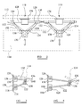
Figure 1 is a diagrammatic view of a pair of actuator arrangements in accordance with one embodiment of the invention, in use. -
Figure 2 is a diagrammatic plan view illustrating an actuator arrangement in accordance with another embodiment of the invention, -
Figures 3 and 4 are side views illustrating the arrangement ofFigure 2 in retracted and extended positions; -
Figures 5 and 6 are views similar toFigures 3 and 4 illustrating a modification; -
Figure 7 is a diagrammatic plan view illustrating another alternative embodiment; -
Figures 8 and 9 are side views illustrating the arrangement ofFigure 7 in retracted and extended positions; -
Figure 10 is a plan view illustrating the operation of the arrangement ofFigure 7 ; and -
Figure 11 is a diagrammatic plan view illustrating a further embodiment. - As illustrated in
Figure 1 , afront spar 10 of an aircraft wing carries a pair ofgearboxes 12. Eachgearbox 12 is arranged to drive respective first andsecond screw shafts screw shafts screw shafts screw shaft - Associated with each
screw shaft respective nut nuts screw shafts screw shafts nuts nut respective screw shaft - The nature of the
gearbox 12 and the handedness of the thread formations are chosen such that when each of thefirst nuts 18 is driven towards the right in the orientation illustrated, thesecond nuts 20 are driven towards the left, and vice versa. Thus, for each actuator arrangement, rotation of thescrew shafts second nuts - Pivotally connected to each
nut respective linkage linkages nuts respective output member 26. - The aircraft wing is provided with a pair of
guide tracks 28 arranged to support and guide the movement of a flight control surface in the form of aslat 30. Theoutput members 26 of the two actuator arrangements are pivotally mounted upon the slat 30. It will be appreciated that the mounting of theoutput members 26 on theslat 30 holds thelinkages nuts - In use, with the
slat 30 in a fully retracted position, the first andsecond nuts slat 30 towards its extended position, either to a fully extended position or to an intermediate position, the first andsecond screw shafts nuts nuts linkages output members 26, driving theoutput members 26 in a direction substantially perpendicular to the axis of rotation of thescrew shafts screw shafts output members 26 are secured to theslat 30, the movement of theoutput members 26 drives theslat 30 towards its extended position. - As mentioned hereinbefore, the
guide tracks 28 support theslat 30 and guide theslat 30 for movement, thus the shape of theguide tracks 28 can be chosen to result in theslat 30 being driven along a desired profile or path of movement the pivotal mounting of theoutput members 26 to theslat 30, and a small amount of angular movement of thenuts - Movement of the
slat 30 in the reverse direction is achieved by rotation of thescrew shafts nuts output members 26 and slat 30 to the position shown. - In order to ensure that both actuator arrangements operate, in use, simultaneously and at the same speed as one another, a
tie member 32 may be provided to tie one of the screw shafts of one actuator arrangement to one of the screw shafts of the other actuator arrangement, thereby ensuring that rotation of these two screw shafts is synchronised. Thetie member 32 may further serve to transmit drive between the actuator arrangements, and between actuator arrangements associated with other control surfaces to be moved simultaneously along with the slat 30. - The nature of the actuator arrangements described hereinbefore is such that they can be accommodated alongside the front spar of the wing and do not need to pass through the front spar. Weakening of the front spar and reinforcement of the front spar can thus be avoided, and it may be possible to avoid having to redesign or place unnecessary design constraints upon, for example, the aircraft's fuel tanks. Further, as mentioned hereinbefore, movement of the slat over a relatively complex profile can be attained.
- It may be possible, by using a more complex form of linkage arrangement, to support and guide the slat for movement using the actuator arrangement alone, avoiding the use of guide tracks.
- Referring next to
Figures 2 to 4 there is illustrated a pair ofactuator arrangements 110 mounted to afront spar 112 of an aircraft's wing and operable to drive aslat panel 114 thereof between retracted and extended positions. - Each
actuator arrangement 110 comprises agearbox 116 secured to thefront spar 112 and arranged to drive respective first andsecond screw shafts 118 for rotation. Thescrew shafts 118 are supported, in use, by the front spar 112 through appropriate support bearings (not shown). Thescrew shafts 118 are arranged coaxially with one another and eachscrew shaft 118 is provided with a screw thread formation (not shown). - Associated with each
screw shaft 118 is arespective nut 120, thenuts 120 being formed with grooves within which are located ball or roller components which also cooperate with the screw thread formations of thescrew shafts 118 such that rotation of thescrew shafts 118, whilst thenuts 120 are held against rotation, causes eachnul 120 to translate along therespective screw shaft 118 in a ball or roller-screw like fashion. - The nature of the
gearbox 116 and the handedness of the thread formations are chosen such that thenuts 120 are either driven towards one another or away one another, depending upon the direction in which the actuator arrangement is being driven. - Pivotally connected to each
nut 120 is arespective linkage linkages actuator arrangement 110 being pivotally connected at their ends remote from thenuts 120 to anoutput member 138. - Also mounted to the
front spar 112, and located above thegearbox 116,shafts 118 andnuts 120 of eachactuator arrangement 110 is asecond gearbox 126 arranged to drivescrew shafts 128 upon whichnuts 130 are mounted, the rotation of thescrew shafts 128 and handedness of the threads thereof being such that thenuts 130 are driven either towards or away from one another.Linkages nut 130 to a connectingmember 136. It will be appreciated that theshafts 128,nuts 130 andlinkages output member 138 is driven by theshafts 118,nuts 120 andlinkages - The connecting
member 136 andoutput member 138 are coupled to one another by aconnector 140 which further serves to mount theslat panel 114 to theoutput member 138. - The
nuts linkages screw shafts linkages output member 138 are such that the attitude of theoutput member 138 is fixed relative to thelinkages connector 140 to theoutput member 138 andconnection member 136 is such that the attitude of theconnection member 136 is fixed relative to theoutput member 138 andlinkages linkages connection member 136 permits relative movement in the attitudes thereof. - In use, with the
slat panel 114 in a fully retracted position, the first andsecond nuts 120 of each actuator arrangement will be spaced apart from one another by a relatively large distance. Similarly, thenuts 130 will be spaced apart from one another. When it is desired to move theslat panel 114 towards its extended position, either to a fully extended position or to an intermediate position, the first andsecond screw shafts 118 of each actuator arrangement are driven to cause thenuts 120 associated therewith to be driven towards one another. The movement of thenuts 120 towards one another is transmitted through the linkages 122,124 to theoutput members 138, driving theoutput members 138 in a direction substantially perpendicular to the axis of rotation of thescrew shafts 118, away from thescrew shafts 118, As theoutput members 138 are secured to theslat panel 114, the movement of theoutput members 138 drives theslat panel 114 towards its extended position. - Simultaneously with this movement the
screw shafts 128 are rotated, driving thenuts 130 towards one another, and this movement is transmitted by thelinkages connection member 136 to theoutput member 138. - As shown in
Figures 3 and 4 , by appropriate control over the rate of movement of theconnection member 136 relative to that of theoutput member 138, the angle of thelinkages output member 138 and theslat panel 114 itself can be controlled and adjusted as theslat panel 114 is moved from its retracted position towards its extended position, thereby enabling movement of theslat panel 114 over a relatively complex path of movement without requiring theslat panel 114 to be guided by guide tracks. As shown inFigures 3 and 4 , the arrangement illustrated is designed such that the angle of attack of theslat panel 114 increases as theslat panel 114 is moved to its extended position. - Retracting movement is achieved by driving the
screw shafts nuts 120 and thenuts 130 apart and causing thelinkages output member 138 to return to the position shown inFigure 3 . - The two sets of
shafts shafts -
Figures 5 and 6 illustrate an arrangement similar to that ofFigures 2 to 4 but in which theconnection member 136 is omitted, both sets oflinkages output member 138. Again, the connections of thelinkages output member 138 are such that the attitude of theoutput member 138 is fixed relative to thelinkages linkages Figures 5 and 6 is very similar to that ofFigures 2 to 4 and so will not be described in further detail. - Referring next to
Figures 7 to 10 , aslat panel 114 is again moveable relative to afront spar 112 by a pair ofactuator arrangements 110. As in the arrangement ofFigures 2 to 4 eachactuator arrangement 110 includes a pair ofscrew shafts 118 rotatable by agearbox 116, eachscrew shaft 118 cooperating with arespective nut 120 such that rotation of eachscrew shaft 118 causes translation of the associatednut 120. In use, thenuts 120 are arranged to translate either towards one another or away from one another, depending upon the direction of the input drive. Eachnut 120 has alinkage output member 138 which is connected to theslat panel 114. The connection of theoutput member 138 to thelinkages slat panel 114 is such that the attitude of theslat panel 114 is fixed relative to that of thelinkages - A
guide track 142 is rigidly connected to thefront spar 112, for example by being rigidly mounted upon thegearbox 116. Afollower 144 carried by asupport bar 146 is arranged to run along theguide track 142, and to hold thesupport bar 146 in an orientation substantially perpendicular to theguide track 142. Thefollower 144 is secured to a central part of thesupport bar 146.Pins 148 carried by thelinkages support bar 146. - The arrangement is such that the
guide track 142,follower 144 andsupport bar 146 provide support for thelinkages output member 138 andslat panel 114. - As shown in
Figures 8 and 9 theguide track 142 is of curved form. - In use, starting from the retracted position shown in
Figure 8 if it is desired to move theslat panel 114 towards its extended position, theactuator arrangements 110 are driven such that thenuts 120 of eachactuator arrangement 110 are driven towards one another, this movement being transmitted to thelinkages output member 138 andslat panel 114 to move as shown inFigure 10 . It will be appreciated that during this movement, thepins 148 drive thesupport bar 146 for movement and move along the slots provided in thesupport bar 146 as shown inFigure 10 , drawing thefollower 144 along theguide track 142 and, as shown inFigure 8 and 9 , this movement results in the attitude of thelinkages output member 138 andslat panel 114 changing as theslat panel 114 is moved towards its extended position. Again, this is achieved without providing guide tracks for the slat panel itself. - Retraction of the
slat panel 114 is achieved by reversing the direction in which the actuators are driven, the reverse movement being along substantially the same path of movement. -
Figure 11 shows an arrangement similar to that ofFigure 7 to 10 but in which thesupport bar 146 is of increased length, protruding beyond thelinkages support bar 146 having twofollowers 144 associated therewith, each running along arespective guide track 142 secured (by means not shown) to thefront spar 112. As twoguide tracks 142 are associated with eachactuator arrangement 110, it may be possible to improve the load bearing capability of theactuator arrangement 110, or alternatively use smaller dimension guide tracks than in the arrangement ofFigure 7 to 10 . - Although the
Figure 11 embodiment only illustrates oneactuator arrangement 110 associated with theslat panel 114, it is anticipated that two such actuator arrangements may be used therewith. - It will be appreciated that where additional stability and control over the angle of attack and vertical position of the
slat panel 114 is required, the actuator arrangement illustrated inFigures 2 to 4 andFigures 5 and 6 , respectively, may be further modified to incorporate aguide track 142,follower 144 andsupport bar 146, for example of the general type illustrated inFigures 7 to 10 or, alternatively, a pair of guide tracks 142, associatedfollowers 144 and an increasedlength support bar 146, for example of the general type illustrated inFigure 11 . - In the arrangements of
Figures 7 to 11 , the angular movement of thelinkages slat 114 is achievable, theslat 114 being non-rotatably secured to theoutput member 138 andlinkages slat 114 and thelinkages - A wide range of modifications and alterations may be made to the arrangements described hereinbefore without departing from the scope of the invention
Claims (15)
- An actuator arrangement comprising a first screw shaft (14, 118), a first nut (18, 120) cooperating with the first screw shaft (14, 118) such that rotation of the first screw shaft (14, 118) causes the first nut (18, 120) to translate thereon, a second screw shaft (16, 118), a second nut (20, 120) cooperating with the second screw shaft (16, 118) such that rotation of the second screw shaft (16, 118) causes the second nut (20, 120) to translate thereon, and first and second linkages (22, 24, 122, 124) connecting the first and second nuts (18, 20, 120), respectively, to an output member (26, 138), rotation of the first and second screw shafts (14, 16, 118) to cause translation of the first and second nuts (18, 20, 120) towards one another causing extending movement of the output member (26, 138) and rotation of the first and second screw shafts (14, 16, 118) to cause translation of the first and second nuts (18, 20, 120) away from one another causing retracting movement of the output member (26, 138).
- An arrangement according to Claim 1, wherein the first and second screw shafts (14, 16, 118) are coaxial with one another.
- An arrangement according to Claim 1 or Claim 2, wherein the output member (26, 138) is designed to accommodate angular, tilting movement of a wing slat connected to the output member (26, 138) relative to the first and second linkages (22, 24, 122, 124).
- An arrangement according to any of the preceding claims, wherein at least a pair of actuator arrangements is associated with a single wing slat.
- An arrangement according to Claim 4, further comprising synchronisation means to ensure that the actuator arrangements are operated simultaneously at the same speed as one another.
- An arrangement according to any of the preceding claims, further comprising guide track means provided to guide the wing slat for movement.
- An arrangement according to any of the preceding claims, further comprising guide means for adjusting the vertical position of the output member (136, 138) relative to a datum position during extending and retracting movement thereof
- An arrangement according to Claim 7, wherein the guide means comprises a guide track (142) along which a follower (144) rides to control the vertical position of the output member (138).
- An arrangement according to Claim 8, wherein the follower (144) is connected to at least one of the linkages (122, 124),
- An arrangement according to Claim 8 or Claim 9, wherein two or more such guide tracks (142) are associated with the actuator arrangement.
- An arrangement according to Claim 7, wherein the guide means comprises a linkage arrangement (132) operated by a second actuator arrangement and connected to the output member (136, 138).
- An arrangement according to Claim 11, wherein the second actuator arrangement comprises a first screw shaft (128), a first nut (130) cooperating with the first screw shaft (128) such that rotation of the first screw shaft (128) causes the first nut (130) to translate thereon, a second screw shaft (128), a second nut (130) cooperating with the second screw shaft (128) such that rotation of the second screw shaft (128) causes the second nut (130) to translate thereon, and first and second linkages (132, 134) connecting the first and second nuts (130), respectively, to the output member (136,138).
- An arrangement according to Claim 11 or Claim 12, wherein the guide means further comprises a guide track (142) along which a follower (144) rides to control the vertical position of the output member (138).
- An arrangement according to Claim 13, wherein the follower (144) is connected to at least one of the linkages (122,124).
- An arrangement according to Claim 13 or Claim 14, wherein two or more such guide tracks (142) are associated with the actuator arrangement.
Applications Claiming Priority (2)
| Application Number | Priority Date | Filing Date | Title |
|---|---|---|---|
| GB0707999A GB0707999D0 (en) | 2007-04-25 | 2007-04-25 | Actuator arrangement |
| GB0709741A GB0709741D0 (en) | 2007-05-22 | 2007-05-22 | Actuator arrangement |
Publications (3)
| Publication Number | Publication Date |
|---|---|
| EP1985893A2 true EP1985893A2 (en) | 2008-10-29 |
| EP1985893A3 EP1985893A3 (en) | 2009-04-15 |
| EP1985893B1 EP1985893B1 (en) | 2010-07-21 |
Family
ID=39637704
Family Applications (1)
| Application Number | Title | Priority Date | Filing Date |
|---|---|---|---|
| EP08251524A Active EP1985893B1 (en) | 2007-04-25 | 2008-04-25 | Flight control surface actuator arrangement |
Country Status (3)
| Country | Link |
|---|---|
| US (1) | US8104710B2 (en) |
| EP (1) | EP1985893B1 (en) |
| DE (1) | DE602008001820D1 (en) |
Cited By (7)
| Publication number | Priority date | Publication date | Assignee | Title |
|---|---|---|---|---|
| EP2433863A3 (en) * | 2010-04-13 | 2012-06-06 | Airbus Operations Limited | Slat support assembly |
| EP2272752A3 (en) * | 2009-07-07 | 2012-06-06 | Goodrich Actuation Systems Limited | Actuator arrangement |
| US8858171B2 (en) | 2009-01-20 | 2014-10-14 | Airbus Operations Limited | Bearing assembly |
| CN107878732A (en) * | 2016-09-30 | 2018-04-06 | 空中客车德国运营有限责任公司 | System for driving and guiding trailing edge control surface |
| US20180273161A1 (en) * | 2017-03-24 | 2018-09-27 | Airbus Operations Gmbh | Wing for an aircraft |
| EP3501978A1 (en) * | 2017-12-21 | 2019-06-26 | Airbus Operations GmbH | Wing for an aircraft |
| US10822072B2 (en) | 2017-03-24 | 2020-11-03 | Airbus Operations Gmbh | Wing for an aircraft |
Families Citing this family (14)
| Publication number | Priority date | Publication date | Assignee | Title |
|---|---|---|---|---|
| DE102007001741A1 (en) * | 2007-01-11 | 2008-07-17 | Siemens Ag | Device for linear movement of a valve member |
| GB0808349D0 (en) * | 2008-05-09 | 2008-06-18 | Airbus Uk Ltd | Spoiler deployment mechanism |
| GB0823392D0 (en) * | 2008-12-23 | 2009-01-28 | Goodrich Actuation Systems Ltd | Drive arrangement |
| GB0917693D0 (en) * | 2009-10-09 | 2009-11-25 | Goodrich Actuation Systems Ltd | Actuator arrangement |
| EP2496473B1 (en) * | 2009-11-04 | 2020-09-30 | John Mcmurray Clark | A compound motion structure |
| DE102010053396B4 (en) | 2010-12-03 | 2014-12-24 | Airbus Defence and Space GmbH | Transmission of a control force |
| DE102011014835B4 (en) * | 2011-03-23 | 2015-09-03 | Airbus Operations Gmbh | Apparatus for adjusting a control surface of an aircraft model, control unit, aircraft model and use of an aircraft model |
| US9586675B2 (en) * | 2014-06-09 | 2017-03-07 | The Boeing Company | Apparatus and method for arrestment of a flight control surface |
| US10030695B2 (en) * | 2015-07-30 | 2018-07-24 | Nec Corporation | Multi-degree-of-freedom adjustment mechanism |
| RU2619487C2 (en) * | 2015-09-14 | 2017-05-16 | И-Кан Ан | Parallel circuit screw gear |
| EP3498596A1 (en) * | 2017-12-14 | 2019-06-19 | Tallinn University of Technology | Actuating mechanism for trailing edge flaps and leading edge slats |
| KR102648067B1 (en) * | 2021-09-07 | 2024-03-18 | (주)미래컴퍼니 | Device transmitting driving force for surgical instruments and surgical instrument including the same |
| DE102022124050B3 (en) * | 2022-09-20 | 2023-12-07 | Syntegon Technology Gmbh | Transport device |
| CN116241149A (en) * | 2022-12-22 | 2023-06-09 | 重庆璧合科技有限责任公司 | Automobile tailgate opening and closing system |
Family Cites Families (17)
| Publication number | Priority date | Publication date | Assignee | Title |
|---|---|---|---|---|
| US2698753A (en) * | 1950-07-18 | 1955-01-04 | Globe Auto Glass Co | Window regulator |
| US3229545A (en) | 1963-11-26 | 1966-01-18 | Apogee Consultants & Res Inc | Actuator |
| US4284254A (en) * | 1980-02-13 | 1981-08-18 | The United States Of America As Represented By The Secretary Of The Air Force | Low profile precision actuator |
| JP2627235B2 (en) | 1992-01-25 | 1997-07-02 | オークマ株式会社 | Mold clamping drive |
| US5378282A (en) | 1993-06-28 | 1995-01-03 | Pollard; Willard L. | Robotic tool manipulating apparatus |
| US5651513A (en) * | 1995-03-01 | 1997-07-29 | Northrop Grumman Corporation | Linear flap drive system |
| EP0791438B1 (en) | 1996-02-07 | 2002-05-29 | Verein Deutscher Werkzeugmaschinenfabriken e.V. (VDW) | Device for moving a body in space |
| US6010097A (en) * | 1997-10-16 | 2000-01-04 | Northrop Grumman Corporation | Scissor linkage type slotted flap mechanism |
| US6382566B1 (en) | 1998-12-29 | 2002-05-07 | The Boeing Company | Method and apparatus for detecting skew and asymmetry of an airplane flap |
| US6378282B1 (en) * | 2000-04-03 | 2002-04-30 | James P. Carlton | Fruit harvesting apparatus |
| ITMI20010830A1 (en) | 2001-04-19 | 2002-10-19 | Consiglio Nazionale Ricerche | PARALLEL KINEMATIC MODULAR AND RECONFIGURABLE ROBOT |
| US20040200928A1 (en) * | 2003-04-14 | 2004-10-14 | Arthur Degenholtz | Actuator and flap arrangement with actuator interconnection |
| DE10328717B3 (en) * | 2003-06-25 | 2004-12-02 | Eads Deutschland Gmbh | Operating device for control flap on rear edge of aircraft wing has pyramid transmission device connected on one side to wing structure and on other to flap |
| US6755376B1 (en) * | 2003-07-10 | 2004-06-29 | James Broberg | Dual control horn |
| DE102004047008A1 (en) * | 2004-09-28 | 2006-03-30 | Liebherr-Aerospace Lindenberg Gmbh | Device for adjusting aircraft altitude fins |
| US7607611B2 (en) * | 2005-05-11 | 2009-10-27 | Honeywell International Inc. | Flight control surface actuation system with redundantly configured and lockable actuator assemblies |
| WO2008121451A2 (en) * | 2007-02-16 | 2008-10-09 | Parker-Hannifin Corporation | Aircraft flight control actuation system with direct acting, force limiting, actuator |
-
2008
- 2008-04-24 US US12/108,907 patent/US8104710B2/en active Active
- 2008-04-25 EP EP08251524A patent/EP1985893B1/en active Active
- 2008-04-25 DE DE602008001820T patent/DE602008001820D1/en active Active
Cited By (12)
| Publication number | Priority date | Publication date | Assignee | Title |
|---|---|---|---|---|
| US8858171B2 (en) | 2009-01-20 | 2014-10-14 | Airbus Operations Limited | Bearing assembly |
| EP2272752A3 (en) * | 2009-07-07 | 2012-06-06 | Goodrich Actuation Systems Limited | Actuator arrangement |
| US8517314B2 (en) | 2009-07-07 | 2013-08-27 | Goodrich Actuation Systems Limited | Actuator arrangement |
| EP2433863A3 (en) * | 2010-04-13 | 2012-06-06 | Airbus Operations Limited | Slat support assembly |
| US8424801B2 (en) | 2010-04-13 | 2013-04-23 | Airbus Operations Limited | Slat support assembly |
| CN107878732A (en) * | 2016-09-30 | 2018-04-06 | 空中客车德国运营有限责任公司 | System for driving and guiding trailing edge control surface |
| US20180273161A1 (en) * | 2017-03-24 | 2018-09-27 | Airbus Operations Gmbh | Wing for an aircraft |
| US10822072B2 (en) | 2017-03-24 | 2020-11-03 | Airbus Operations Gmbh | Wing for an aircraft |
| US11034435B2 (en) * | 2017-03-24 | 2021-06-15 | Airbus Operations Gmbh | Wing for an aircraft |
| EP3501978A1 (en) * | 2017-12-21 | 2019-06-26 | Airbus Operations GmbH | Wing for an aircraft |
| US11136111B2 (en) | 2017-12-21 | 2021-10-05 | Airbus Operations Gmbh | Wing for an aircraft |
| US11713107B2 (en) | 2017-12-21 | 2023-08-01 | Airbus Operations Gmbh | Wing for an aircraft |
Also Published As
| Publication number | Publication date |
|---|---|
| US8104710B2 (en) | 2012-01-31 |
| DE602008001820D1 (en) | 2010-09-02 |
| EP1985893B1 (en) | 2010-07-21 |
| EP1985893A3 (en) | 2009-04-15 |
| US20090200420A1 (en) | 2009-08-13 |
Similar Documents
| Publication | Publication Date | Title |
|---|---|---|
| US8104710B2 (en) | Actuator arrangement | |
| CN102007036B (en) | Slat deployment mechanism | |
| EP2309150B1 (en) | Actuator arrangement | |
| EP2433863B1 (en) | Slat support assembly | |
| CN101959754B (en) | High lift system for aircraft | |
| CN101909991B (en) | High lift system for an aircraft | |
| EP2669188B1 (en) | A hinge assembly for rotatably mounting a control surface on an aircraft | |
| EP2778061A1 (en) | Tiltrotor control system with two rise/fall actuators | |
| EP3501978B1 (en) | Wing for an aircraft | |
| CA2706413A1 (en) | Landing flap kinematics driven by way of a pinion drive | |
| EP4112450A1 (en) | Wing for an aircraft | |
| US6641089B2 (en) | Flap arrangement for varying the aerodynamic lift generated by an aerodynamic element of an aircraft | |
| WO2011070345A1 (en) | Slat support assembly | |
| GB2458683A (en) | Aircraft slat deployment mechanism | |
| CN207711949U (en) | A kind of farm machinery navigation display screen driving device | |
| US5470129A (en) | Adjustable vehicle seat | |
| EP1988308A2 (en) | Actuator | |
| EP3661778B1 (en) | Open roof construction for a vehicle | |
| CN111824390B (en) | Unmanned aerial vehicle with scalable wing | |
| CN101008435A (en) | Multi-degree-of-freedom motion platform used for pose adjustment | |
| CN219371389U (en) | Transmission device for antenna | |
| CN207823767U (en) | A kind of rear stock stop for mold plate shearing machine | |
| CN220488089U (en) | Mechanism for changing output action direction | |
| EP1619119B1 (en) | Wing assembly for an ultralight aircraft, and ultralight aircraft provided with such wing assembly | |
| JP2025176630A (en) | Unmanned aerial vehicle takeoff and landing port |
Legal Events
| Date | Code | Title | Description |
|---|---|---|---|
| PUAI | Public reference made under article 153(3) epc to a published international application that has entered the european phase |
Free format text: ORIGINAL CODE: 0009012 |
|
| AK | Designated contracting states |
Kind code of ref document: A2 Designated state(s): AT BE BG CH CY CZ DE DK EE ES FI FR GB GR HR HU IE IS IT LI LT LU LV MC MT NL NO PL PT RO SE SI SK TR |
|
| AX | Request for extension of the european patent |
Extension state: AL BA MK RS |
|
| PUAL | Search report despatched |
Free format text: ORIGINAL CODE: 0009013 |
|
| AK | Designated contracting states |
Kind code of ref document: A3 Designated state(s): AT BE BG CH CY CZ DE DK EE ES FI FR GB GR HR HU IE IS IT LI LT LU LV MC MT NL NO PL PT RO SE SI SK TR |
|
| AX | Request for extension of the european patent |
Extension state: AL BA MK RS |
|
| 17P | Request for examination filed |
Effective date: 20091014 |
|
| AKX | Designation fees paid |
Designated state(s): DE ES FR GB IT |
|
| GRAP | Despatch of communication of intention to grant a patent |
Free format text: ORIGINAL CODE: EPIDOSNIGR1 |
|
| RBV | Designated contracting states (corrected) |
Designated state(s): DE ES FR GB IT |
|
| RIC1 | Information provided on ipc code assigned before grant |
Ipc: F16H 37/12 20060101AFI20100316BHEP |
|
| RTI1 | Title (correction) |
Free format text: FLIGHT CONTROL SURFACE ACTUATOR ARRANGEMENT |
|
| GRAS | Grant fee paid |
Free format text: ORIGINAL CODE: EPIDOSNIGR3 |
|
| GRAA | (expected) grant |
Free format text: ORIGINAL CODE: 0009210 |
|
| AK | Designated contracting states |
Kind code of ref document: B1 Designated state(s): DE ES FR GB IT |
|
| REG | Reference to a national code |
Ref country code: GB Ref legal event code: FG4D |
|
| REF | Corresponds to: |
Ref document number: 602008001820 Country of ref document: DE Date of ref document: 20100902 Kind code of ref document: P |
|
| PLBE | No opposition filed within time limit |
Free format text: ORIGINAL CODE: 0009261 |
|
| STAA | Information on the status of an ep patent application or granted ep patent |
Free format text: STATUS: NO OPPOSITION FILED WITHIN TIME LIMIT |
|
| PG25 | Lapsed in a contracting state [announced via postgrant information from national office to epo] |
Ref country code: IT Free format text: LAPSE BECAUSE OF FAILURE TO SUBMIT A TRANSLATION OF THE DESCRIPTION OR TO PAY THE FEE WITHIN THE PRESCRIBED TIME-LIMIT Effective date: 20100721 |
|
| 26N | No opposition filed |
Effective date: 20110426 |
|
| PG25 | Lapsed in a contracting state [announced via postgrant information from national office to epo] |
Ref country code: ES Free format text: LAPSE BECAUSE OF FAILURE TO SUBMIT A TRANSLATION OF THE DESCRIPTION OR TO PAY THE FEE WITHIN THE PRESCRIBED TIME-LIMIT Effective date: 20101101 |
|
| REG | Reference to a national code |
Ref country code: DE Ref legal event code: R097 Ref document number: 602008001820 Country of ref document: DE Effective date: 20110426 |
|
| REG | Reference to a national code |
Ref country code: FR Ref legal event code: PLFP Year of fee payment: 9 |
|
| REG | Reference to a national code |
Ref country code: FR Ref legal event code: PLFP Year of fee payment: 10 |
|
| REG | Reference to a national code |
Ref country code: FR Ref legal event code: PLFP Year of fee payment: 11 |
|
| PGFP | Annual fee paid to national office [announced via postgrant information from national office to epo] |
Ref country code: DE Payment date: 20250319 Year of fee payment: 18 |
|
| PGFP | Annual fee paid to national office [announced via postgrant information from national office to epo] |
Ref country code: GB Payment date: 20260319 Year of fee payment: 19 |
|
| PGFP | Annual fee paid to national office [announced via postgrant information from national office to epo] |
Ref country code: FR Payment date: 20260320 Year of fee payment: 19 |