EP1985870A2 - A joint for a shape memory material - Google Patents
A joint for a shape memory material Download PDFInfo
- Publication number
- EP1985870A2 EP1985870A2 EP08251150A EP08251150A EP1985870A2 EP 1985870 A2 EP1985870 A2 EP 1985870A2 EP 08251150 A EP08251150 A EP 08251150A EP 08251150 A EP08251150 A EP 08251150A EP 1985870 A2 EP1985870 A2 EP 1985870A2
- Authority
- EP
- European Patent Office
- Prior art keywords
- component
- shape memory
- joint
- memory material
- half dovetail
- Prior art date
- Legal status (The legal status is an assumption and is not a legal conclusion. Google has not performed a legal analysis and makes no representation as to the accuracy of the status listed.)
- Granted
Links
- 239000012781 shape memory material Substances 0.000 title claims abstract description 40
- 229910001285 shape-memory alloy Inorganic materials 0.000 claims description 11
- 229910045601 alloy Inorganic materials 0.000 claims description 8
- 239000000956 alloy Substances 0.000 claims description 8
- 229910001000 nickel titanium Inorganic materials 0.000 claims description 6
- 238000010438 heat treatment Methods 0.000 claims description 4
- 239000002184 metal Substances 0.000 claims description 3
- 229910052751 metal Inorganic materials 0.000 claims description 3
- 229910001069 Ti alloy Inorganic materials 0.000 claims description 2
- 239000007789 gas Substances 0.000 description 9
- 239000003570 air Substances 0.000 description 6
- 238000005452 bending Methods 0.000 description 3
- 239000000446 fuel Substances 0.000 description 3
- 230000001141 propulsive effect Effects 0.000 description 3
- 239000012080 ambient air Substances 0.000 description 2
- 230000000295 complement effect Effects 0.000 description 2
- 238000000034 method Methods 0.000 description 2
- 239000010936 titanium Substances 0.000 description 2
- RTAQQCXQSZGOHL-UHFFFAOYSA-N Titanium Chemical compound [Ti] RTAQQCXQSZGOHL-UHFFFAOYSA-N 0.000 description 1
- HZEWFHLRYVTOIW-UHFFFAOYSA-N [Ti].[Ni] Chemical compound [Ti].[Ni] HZEWFHLRYVTOIW-UHFFFAOYSA-N 0.000 description 1
- 238000002485 combustion reaction Methods 0.000 description 1
- 230000000694 effects Effects 0.000 description 1
- 230000002349 favourable effect Effects 0.000 description 1
- 229910000765 intermetallic Inorganic materials 0.000 description 1
- 239000000203 mixture Substances 0.000 description 1
- 238000007789 sealing Methods 0.000 description 1
- 229910052719 titanium Inorganic materials 0.000 description 1
- 230000007704 transition Effects 0.000 description 1
- 238000011144 upstream manufacturing Methods 0.000 description 1
Images


Classifications
-
- B—PERFORMING OPERATIONS; TRANSPORTING
- B64—AIRCRAFT; AVIATION; COSMONAUTICS
- B64D—EQUIPMENT FOR FITTING IN OR TO AIRCRAFT; FLIGHT SUITS; PARACHUTES; ARRANGEMENT OR MOUNTING OF POWER PLANTS OR PROPULSION TRANSMISSIONS IN AIRCRAFT
- B64D29/00—Power-plant nacelles, fairings or cowlings
-
- F—MECHANICAL ENGINEERING; LIGHTING; HEATING; WEAPONS; BLASTING
- F16—ENGINEERING ELEMENTS AND UNITS; GENERAL MEASURES FOR PRODUCING AND MAINTAINING EFFECTIVE FUNCTIONING OF MACHINES OR INSTALLATIONS; THERMAL INSULATION IN GENERAL
- F16B—DEVICES FOR FASTENING OR SECURING CONSTRUCTIONAL ELEMENTS OR MACHINE PARTS TOGETHER, e.g. NAILS, BOLTS, CIRCLIPS, CLAMPS, CLIPS OR WEDGES; JOINTS OR JOINTING
- F16B2200/00—Constructional details of connections not covered for in other groups of this subclass
- F16B2200/30—Dovetail-like connections
-
- F—MECHANICAL ENGINEERING; LIGHTING; HEATING; WEAPONS; BLASTING
- F16—ENGINEERING ELEMENTS AND UNITS; GENERAL MEASURES FOR PRODUCING AND MAINTAINING EFFECTIVE FUNCTIONING OF MACHINES OR INSTALLATIONS; THERMAL INSULATION IN GENERAL
- F16B—DEVICES FOR FASTENING OR SECURING CONSTRUCTIONAL ELEMENTS OR MACHINE PARTS TOGETHER, e.g. NAILS, BOLTS, CIRCLIPS, CLAMPS, CLIPS OR WEDGES; JOINTS OR JOINTING
- F16B2200/00—Constructional details of connections not covered for in other groups of this subclass
- F16B2200/77—Use of a shape-memory material
Definitions
- the present invention relates to a joint for a shape memory material and in particular to a joint between a shape memory material component and another component, more particularly to a joint between a shape memory alloy component and another component.
- Shape memory alloys have previously been limited to small section components and relatively fragile components.
- shape memory alloy components particularly NiTi shape memory alloys
- other components are notoriously difficult with most applications using mechanical joints.
- the use of welded joints has been investigated but an acceptable solution has not been found. Welded joints are not practical, acceptable, because brittle intermetallics are formed.
- the present invention seeks to provide a novel joint between a shape memory material component and another component, which reduces, preferably overcomes, the above-mentioned problem.
- the present invention provides a joint between a first component and a second component, the second component comprising a shape memory material component, the first component having a half dovetail shaped slot, the shape memory material second component having a half dovetail shaped attachment feature and the half dovetail shaped attachment feature of the shape memory material second component locating in the half dovetail shaped slot in the first component.
- the second shape memory material comprises a shape memory alloy.
- the second shape memory material comprises a NiTi alloy.
- the first component comprises a metal or an alloy.
- the first component comprises a Ti alloy.
- the first component and the second component constitute a tab, the tab extending in a downstream direction from a downstream end of a gas turbine exhaust nozzle, the second component comprising an actuator to move the tab between a second non-deployed position and a first deployed position.
- the exhaust nozzle may be a fan exhaust nozzle or a core exhaust nozzle.
- the first component is joined to the second component at the downstream end of the tab.
- heating means to heat the second component such that the second component moves the first component between the second non-deployed position and the first deployed position.
- a turbofan gas turbine engine 10 as shown in figure 1 , comprises in axial flow series an air intake 5, a propulsive fan 2, a core engine 4 and an exhaust nozzle assembly 16 all disposed about an engine axis 1.
- the core engine 4 comprises in axial flow series a series of compressors 6, a combustor 8 and a series of turbines 9.
- the direction of airflow through the turbofan gas turbine engine 10 in operation is indicated by arrow A and the terms upstream and downstream are used with reference to this general flow direction.
- Air is drawn through the air intake 5 and is compressed by the fan 2.
- the airflow from the fan 2 is split between a flow through the core engine 4 and a bypass flow.
- the flow through the core engine 4 flows through the compressors 6 where it is further compressed and into the combustor 8 where it is mixed with fuel and the fuel is burnt in the air in the combustor 8.
- the combustion of the fuel in the compressed air in the combustor 8 produces hot gases, which exit the combustor 8 and flow downstream through and drive the turbines 9.
- the turbines 9 drive the compressors 6 and fan 2 via shafts 11 which drivingly connect the turbines 9 with the compressors 6 and the fan 2.
- the exhaust gases leaving the turbine 9 flow through the exhaust nozzle assembly 16 to provide propulsive thrust.
- the remainder of the air from the fan 2, the bypass flow flows within a bypass duct 7 around the core engine 4.
- the bypass flow which has been accelerated by the fan 2 also flows to the exhaust nozzle assembly 16 where it is exhausted, as a bypass exhaust stream to provide further, the majority of the, propulsive thrust.
- the velocity of the bypass exhaust stream is significantly lower than the velocity of the core engine exhaust stream. Turbulent mixing of the bypass exhaust stream and the core engine exhaust stream occurs in the region of, and downstream of, the exhaust nozzle assembly 16. These two exhaust streams also mix with the ambient air surrounding and downstream of the exhaust nozzle assembly 16. This mixing of the two exhaust streams and the ambient air produces noise.
- the exhaust nozzle assembly 16 comprises two concentric exhaust nozzles, a radially outer bypass exhaust nozzle 12 and a radially inner core exhaust nozzle 14.
- the core exhaust nozzle 14 is defined at its radially outer extent by a generally frusto-conical core nozzle wall 15 and at its radially inner extent by a frusto-conical engine plug structure 22.
- the bypass exhaust nozzle 12 is defined its radially outer extent by a nacelle 17 and at its radially inner extent by the nozzle wall 15.
- the exhaust nozzle assembly 16 is shown more clearly in figure 2 and it comprises noise reduction means comprising a number of tabs.
- a plurality of circumferentially spaced tabs 20 extend from the downstream end of the core exhaust nozzle 14 and in particular from the downstream end of the frusto-conical core nozzle wall 15.
- the tabs 20 are of trapezoidal shape with the sides of the tabs 20 circumferentially tapering away from each other in a downstream direction to form a plurality of circumferentially disposed notches, or spaces, 21 defined between adjacent tabs 20.
- the notches 21 are complementary to the shape of the tabs 20 and are of trapezoidal shape with the notches 21 increasing in dimension in a downstream direction.
- the tabs 20 and notches 21 are evenly circumferentially spaced.
- a plurality of circumferentially spaced tabs 18 extend from the downstream end of the bypass exhaust nozzle 12 and in particular from the downstream end of the nacelle 17.
- the tabs 18 are of trapezoidal shape with the sides of the tabs 18 circumferentially tapering away from each other in a downstream direction to form a plurality of circumferentially disposed notches, or spaces, 19 defined between adjacent tabs 18.
- the notches 19 are complementary to the shape of the tabs 18 and are of trapezoidal shape with the notches 19 increasing in dimension in a downstream direction.
- the tabs 18 and notches 19 are evenly circumferentially spaced.
- the tabs 18, 20, as shown in figures 3 and 4 comprise a first component 30 and a second component 32.
- the second component 32 comprises a shape memory material component.
- the first component 30 has a half dovetail shaped slot 34 and the shape memory material second component 32 has a half dovetail shaped attachment feature 36 and the half dovetail shaped attachment feature 36 of the shape memory material second component 32 locates in the half dovetail shaped slot 34 in the first component 30.
- the second shape memory material comprises a shape memory alloy, and for example the second shape memory material comprises a nickel-titanium, NiTi, alloy.
- the first component 30 comprises a metal or an alloy, for example the first component 30 comprises a titanium, Ti, alloy.
- the first component 30 and the second component 32 together constitute a tab 18, 20 and the tab 18, 20 extends in a downstream direction from a downstream end of a gas turbine exhaust nozzle, the fan, or bypass, exhaust nozzle 12 or the core exhaust nozzle 14.
- the second component 32 comprises an actuator to move the tab 18, 20 between a second non-deployed position and a first deployed position.
- the first component 30 is joined to the second component 32 at the downstream end 18B of the tab 18, 20. There are heating means to heat the second component 32 such that the second component 32 moves the first component 30 between the second non-deployed position and the first deployed position.
- the heating means may comprise electrical or other suitable heaters.
- the first component 30 is also joined to the second component 32 at axially spaced positions 31 by screws, bolts or rivets.
- the half dovetail attachment feature 36 is provided at a first end 38 of the second component 32 and the half dovetail attachment feature 36 comprises a projection 44 extending from a first side 40 of the half dovetail attachment feature 36 and a flat surface 46 on a second side 42 of the half dovetail attachment feature 36.
- the half dovetail slot 34 comprises a recess 52 extending from a first side 48 of the half dovetail slot 34 and a flat surface 54 on a second side 50 of the half dovetail slot 34.
- the projection 44 on the half dovetail attachment feature 36 locates in the recess 52.
- Point A of the joint between the half dovetail slot 34 in the first component 30 and the half dovetail attachment feature 36 of the shape memory material second component 32 is arranged such that the flat surface 46 on the second side 42 of the second component 32 and the flat surface 54 on the second side 50 of the first component 30 are substantially free to slide relative to each other, to significantly reduce the bending stresses at point D in the first component 30 and allow a thinner section at point D and hence allow a thinner section of the first component 30.
- Point B of the joint is the point where the first side 48 of the half dovetail slot 34 in the first component 30 takes most of the load from the projection 44 on the first side 40 of the half dovetail attachment feature 36 of the shape memory material second component 32.
- the load is transferred directly by abutment from the projection 44 of the half dovetail attachment feature 36 of the second component 32 to the first side 48 of the half dovetail slot 34 in the first component 30.
- Point C of the joint is the point where the first side 48 of the half dovetail slot 34 in the first component 30 is arranged such that under all load conditions, especially when point E on the shape memory material second component 32 moves upwards in figure 3 , it has a positive closing load.
- the half dovetail attachment feature 36 shape memory material second component 32 is arranged to have a smooth transition between points F and G to minimise stresses during operation.
- the net effect is a smooth, thin, method of joining a shape memory material second component 32 to a first component 30 and converting tension and varying angles in the shape memory material second component 32 into bending in the first component 30.
- each tab 18, 20 is positioned such that the shape memory material second component 32 is positioned radially within the first component 30.
- the shape memory material second components 32 are heated in operation to cause the shape memory material components 32 to change shape and each shape memory material second component 32 applies a tensile force on the first component 30 of the respective tab 18.
- the tensile force applied by the shape memory material second component 32 causes the first component 30 of the respective tab 18 to bend such that the downstream end 18B of the respective tab 18 moves substantially radially inwards to the deployed position as shown by arrow R in figure 3 .
- the shape memory material second components 32 are not heated the first component 30 of the respective tab 18 returns to its original position and the downstream end 18B of the tab 18 moves substantially radially outwards to the non-deployed position shown in figure 3 .
- FIG. 5 A further variation of the joint is shown in figure 5 , and this differs in that the first side 48 of the half dovetail slot 34 in' the first component 30 also has a second recess 56 to define a lip 58 between the recess 52 and the second recess 56.
- This lip 58 is intentionally weakened by the second recess 56 to provide controlled bending of the lip 58 to reduce the interface loads between the projection 44 on the first side 42 on the half dovetail attachment feature 36 on the second component 32 and the first side 48 on the half dovetail slot 34 in the first component 30.
- the present invention has been described with reference to the shape memory material second component being positioned radially within the first component and to move the first component from a non-deployed position to a deployed position to change the shape of a tab, it may be equally possible for the shape memory material second component to be positioned radially outside the first component and to move the first component from a non-deployed position to a deployed position to change the shape of a tab or other member.
- tabs 80 and 82 there are two sets of tabs 80 and 82.
- the tabs 80 are rigidly fixed in a deployed position and the tabs 82 comprise a first component 30 and a shape memory material second component 32.
- the tabs 82 are movable between a deployed position as shown in figure 6 and a non-deployed position, where they are circumferentially aligned with tabs 80.
- At take off and climb the tabs 82 are deployed for noise reduction and the exit area of the nozzle is enlarged. The enlargement reduces the velocity of the gas stream and intrinsically reduces noise.
- the shape memory material second component 32 is positioned radially outside the first component 30 and moves the first component 30 from a non-deployed position to a deployed position to change the shape of the tab 82.
- the advantage of the present invention is that it allows a shape memory material component to be joined to another component with a mechanical joint and not a metallurgical joint.
- the joint is thin. The joint minimises stresses in both the components.
- the half dovetail joint provides a method of fixing and maintaining a more favourable stress condition on the shape memory material second component, which might otherwise undergo excessive strain when in an easily deformed, cold, condition.
Landscapes
- Engineering & Computer Science (AREA)
- Aviation & Aerospace Engineering (AREA)
- Structures Of Non-Positive Displacement Pumps (AREA)
- Connection Of Plates (AREA)
- Joining Of Building Structures In Genera (AREA)
Abstract
Description
- The present invention relates to a joint for a shape memory material and in particular to a joint between a shape memory material component and another component, more particularly to a joint between a shape memory alloy component and another component.
- Shape memory alloys have previously been limited to small section components and relatively fragile components.
- There is a requirement for large, high integrity, components with embedded shape memory alloy actuators. Large, high integrity, components comprising parent alloys components/structures and shape memory alloy actuators/components are required and these must be joined under high loading.
- The joining of shape memory alloy components, particularly NiTi shape memory alloys, to other components is notoriously difficult with most applications using mechanical joints. The use of welded joints has been investigated but an acceptable solution has not been found. Welded joints are not practical, acceptable, because brittle intermetallics are formed.
- Accordingly the present invention seeks to provide a novel joint between a shape memory material component and another component, which reduces, preferably overcomes, the above-mentioned problem.
- Accordingly the present invention provides a joint between a first component and a second component, the second component comprising a shape memory material component, the first component having a half dovetail shaped slot, the shape memory material second component having a half dovetail shaped attachment feature and the half dovetail shaped attachment feature of the shape memory material second component locating in the half dovetail shaped slot in the first component.
- Preferably the second shape memory material comprises a shape memory alloy.
- Preferably the second shape memory material comprises a NiTi alloy.
- Preferably the first component comprises a metal or an alloy.
- Preferably the first component comprises a Ti alloy.
- Preferably the first component and the second component constitute a tab, the tab extending in a downstream direction from a downstream end of a gas turbine exhaust nozzle, the second component comprising an actuator to move the tab between a second non-deployed position and a first deployed position.
- The exhaust nozzle may be a fan exhaust nozzle or a core exhaust nozzle.
- Preferably the first component is joined to the second component at the downstream end of the tab.
- Preferably there are heating means to heat the second component such that the second component moves the first component between the second non-deployed position and the first deployed position.
- The present invention will be more fully described by way of example with reference to the accompanying drawings in which:-
-
Figure 1 shows a turbofan gas turbine engine having an exhaust nozzle having noise reducing tabs comprising components joined according to the present invention. -
Figure 2 is an enlarged perspective view of the exhaust nozzle having noise reducing tabs comprising components joined according to the present invention. -
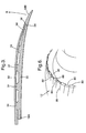
Figure 3 is an enlarged cross-sectional view of a noise reducing tab comprising components joined according to the present invention. -
Figure 4 is a further enlarged cross-sectional view of the joint between the components of the tab shown infigure 3 . -
Figure 5 is a further enlarged alternative cross-sectional view of the joint between the components of the tab shown infigure 3 . -
Figure 6 is an enlarged perspective view of an alternative exhaust nozzle having noise reducing tables comprising components joined according to the present invention. - A turbofan
gas turbine engine 10, as shown infigure 1 , comprises in axial flow series anair intake 5, apropulsive fan 2, acore engine 4 and anexhaust nozzle assembly 16 all disposed about anengine axis 1. Thecore engine 4 comprises in axial flow series a series ofcompressors 6, acombustor 8 and a series ofturbines 9. The direction of airflow through the turbofangas turbine engine 10 in operation is indicated by arrow A and the terms upstream and downstream are used with reference to this general flow direction. Air is drawn through theair intake 5 and is compressed by thefan 2. The airflow from thefan 2 is split between a flow through thecore engine 4 and a bypass flow. The flow through thecore engine 4 flows through thecompressors 6 where it is further compressed and into thecombustor 8 where it is mixed with fuel and the fuel is burnt in the air in thecombustor 8. The combustion of the fuel in the compressed air in thecombustor 8 produces hot gases, which exit thecombustor 8 and flow downstream through and drive theturbines 9. Theturbines 9 drive thecompressors 6 andfan 2 viashafts 11 which drivingly connect theturbines 9 with thecompressors 6 and thefan 2. - The exhaust gases leaving the
turbine 9 flow through theexhaust nozzle assembly 16 to provide propulsive thrust. The remainder of the air from thefan 2, the bypass flow, flows within abypass duct 7 around thecore engine 4. The bypass flow, which has been accelerated by thefan 2 also flows to theexhaust nozzle assembly 16 where it is exhausted, as a bypass exhaust stream to provide further, the majority of the, propulsive thrust. - The velocity of the bypass exhaust stream is significantly lower than the velocity of the core engine exhaust stream. Turbulent mixing of the bypass exhaust stream and the core engine exhaust stream occurs in the region of, and downstream of, the
exhaust nozzle assembly 16. These two exhaust streams also mix with the ambient air surrounding and downstream of theexhaust nozzle assembly 16. This mixing of the two exhaust streams and the ambient air produces noise. - The
exhaust nozzle assembly 16 comprises two concentric exhaust nozzles, a radially outerbypass exhaust nozzle 12 and a radially innercore exhaust nozzle 14. Thecore exhaust nozzle 14 is defined at its radially outer extent by a generally frusto-conicalcore nozzle wall 15 and at its radially inner extent by a frusto-conicalengine plug structure 22. Thebypass exhaust nozzle 12 is defined its radially outer extent by anacelle 17 and at its radially inner extent by thenozzle wall 15. - The
exhaust nozzle assembly 16 is shown more clearly infigure 2 and it comprises noise reduction means comprising a number of tabs. A plurality of circumferentially spacedtabs 20 extend from the downstream end of thecore exhaust nozzle 14 and in particular from the downstream end of the frusto-conicalcore nozzle wall 15. As shown thetabs 20 are of trapezoidal shape with the sides of thetabs 20 circumferentially tapering away from each other in a downstream direction to form a plurality of circumferentially disposed notches, or spaces, 21 defined betweenadjacent tabs 20. Thenotches 21 are complementary to the shape of thetabs 20 and are of trapezoidal shape with thenotches 21 increasing in dimension in a downstream direction. Thetabs 20 andnotches 21 are evenly circumferentially spaced. - Similarly a plurality of circumferentially spaced
tabs 18 extend from the downstream end of thebypass exhaust nozzle 12 and in particular from the downstream end of thenacelle 17. As shown thetabs 18 are of trapezoidal shape with the sides of thetabs 18 circumferentially tapering away from each other in a downstream direction to form a plurality of circumferentially disposed notches, or spaces, 19 defined betweenadjacent tabs 18. Thenotches 19 are complementary to the shape of thetabs 18 and are of trapezoidal shape with thenotches 19 increasing in dimension in a downstream direction. Thetabs 18 andnotches 19 are evenly circumferentially spaced. - The
tabs figures 3 and4 , comprise afirst component 30 and asecond component 32. Thesecond component 32 comprises a shape memory material component. Thefirst component 30 has a half dovetail shapedslot 34 and the shape memory materialsecond component 32 has a half dovetail shapedattachment feature 36 and the half dovetail shapedattachment feature 36 of the shape memory materialsecond component 32 locates in the half dovetail shapedslot 34 in thefirst component 30. The second shape memory material comprises a shape memory alloy, and for example the second shape memory material comprises a nickel-titanium, NiTi, alloy. Thefirst component 30 comprises a metal or an alloy, for example thefirst component 30 comprises a titanium, Ti, alloy. - The
first component 30 and thesecond component 32 together constitute atab tab exhaust nozzle 12 or thecore exhaust nozzle 14. Thesecond component 32 comprises an actuator to move thetab - The
first component 30 is joined to thesecond component 32 at thedownstream end 18B of thetab second component 32 such that thesecond component 32 moves thefirst component 30 between the second non-deployed position and the first deployed position. The heating means may comprise electrical or other suitable heaters. Thefirst component 30 is also joined to thesecond component 32 at axially spacedpositions 31 by screws, bolts or rivets. - The half
dovetail attachment feature 36 is provided at afirst end 38 of thesecond component 32 and the halfdovetail attachment feature 36 comprises aprojection 44 extending from afirst side 40 of the halfdovetail attachment feature 36 and aflat surface 46 on asecond side 42 of the halfdovetail attachment feature 36. Thehalf dovetail slot 34 comprises arecess 52 extending from afirst side 48 of thehalf dovetail slot 34 and aflat surface 54 on asecond side 50 of thehalf dovetail slot 34. Theprojection 44 on the half dovetail attachment feature 36 locates in therecess 52. - Point A of the joint between the
half dovetail slot 34 in thefirst component 30 and the halfdovetail attachment feature 36 of the shape memory materialsecond component 32 is arranged such that theflat surface 46 on thesecond side 42 of thesecond component 32 and theflat surface 54 on thesecond side 50 of thefirst component 30 are substantially free to slide relative to each other, to significantly reduce the bending stresses at point D in thefirst component 30 and allow a thinner section at point D and hence allow a thinner section of thefirst component 30. - Point B of the joint is the point where the
first side 48 of thehalf dovetail slot 34 in thefirst component 30 takes most of the load from theprojection 44 on thefirst side 40 of the halfdovetail attachment feature 36 of the shape memory materialsecond component 32. The load is transferred directly by abutment from theprojection 44 of the halfdovetail attachment feature 36 of thesecond component 32 to thefirst side 48 of thehalf dovetail slot 34 in thefirst component 30. - Point C of the joint is the point where the
first side 48 of thehalf dovetail slot 34 in thefirst component 30 is arranged such that under all load conditions, especially when point E on the shape memory materialsecond component 32 moves upwards infigure 3 , it has a positive closing load. - The half
dovetail attachment feature 36 shape memory materialsecond component 32 is arranged to have a smooth transition between points F and G to minimise stresses during operation. The net effect is a smooth, thin, method of joining a shape memory materialsecond component 32 to afirst component 30 and converting tension and varying angles in the shape memory materialsecond component 32 into bending in thefirst component 30. - In use each
tab second component 32 is positioned radially within thefirst component 30. The shape memory materialsecond components 32 are heated in operation to cause the shapememory material components 32 to change shape and each shape memory materialsecond component 32 applies a tensile force on thefirst component 30 of therespective tab 18. The tensile force applied by the shape memory materialsecond component 32 causes thefirst component 30 of therespective tab 18 to bend such that thedownstream end 18B of therespective tab 18 moves substantially radially inwards to the deployed position as shown by arrow R infigure 3 . When the shape memory materialsecond components 32 are not heated thefirst component 30 of therespective tab 18 returns to its original position and thedownstream end 18B of thetab 18 moves substantially radially outwards to the non-deployed position shown infigure 3 . - A further variation of the joint is shown in
figure 5 , and this differs in that thefirst side 48 of thehalf dovetail slot 34 in' thefirst component 30 also has asecond recess 56 to define alip 58 between therecess 52 and thesecond recess 56. Thislip 58 is intentionally weakened by thesecond recess 56 to provide controlled bending of thelip 58 to reduce the interface loads between theprojection 44 on thefirst side 42 on the halfdovetail attachment feature 36 on thesecond component 32 and thefirst side 48 on thehalf dovetail slot 34 in thefirst component 30. - Although the present invention has been described with reference to the shape memory material second component being positioned radially within the first component and to move the first component from a non-deployed position to a deployed position to change the shape of a tab, it may be equally possible for the shape memory material second component to be positioned radially outside the first component and to move the first component from a non-deployed position to a deployed position to change the shape of a tab or other member.
- In these circumstances, as shown in
figure 6 there are two sets oftabs tabs 80 are rigidly fixed in a deployed position and thetabs 82 comprise afirst component 30 and a shape memory materialsecond component 32. Thetabs 82 are movable between a deployed position as shown infigure 6 and a non-deployed position, where they are circumferentially aligned withtabs 80. At take off and climb thetabs 82 are deployed for noise reduction and the exit area of the nozzle is enlarged. The enlargement reduces the velocity of the gas stream and intrinsically reduces noise. At cruise thetabs 82 are in the non-deployed position and theedges tabs second component 32 is positioned radially outside thefirst component 30 and moves thefirst component 30 from a non-deployed position to a deployed position to change the shape of thetab 82. - Although the present invention has been described with reference to a NiTi shape memory alloy it is equally applicable to other shape memory alloys.
- The advantage of the present invention is that it allows a shape memory material component to be joined to another component with a mechanical joint and not a metallurgical joint. The joint is thin. The joint minimises stresses in both the components.
- The half dovetail joint provides a method of fixing and maintaining a more favourable stress condition on the shape memory material second component, which might otherwise undergo excessive strain when in an easily deformed, cold, condition.
Claims (10)
- A joint between a first component (30) and a second shape memory material component (32) characterised in that, the first component (30) having a half dovetail shaped slot (34), the shape memory material second component (32) having a half dovetail shaped attachment feature (36) and the half dovetail shaped attachment feature (36) of the shape memory material second component (32) locating in the half dovetail shaped slot (34) in the first component (30).
- A joint as claimed in claim 1 wherein the second shape memory material component (32) comprises a shape memory alloy.
- A joint as claimed in claim 2 wherein the second shape memory material component (32) comprises a NiTi alloy.
- A joint as claimed in any of claims 1 to 3 wherein the first component (30) comprises a metal or an alloy.
- A joint as claimed in claim 4 wherein the first component (30) comprises a Ti alloy.
- A joint as claimed in any of claims 1 to 5 wherein the first component (30) and the second component (32) constitute a tab (20, 18), the tab (20, 18) extending in a downstream direction from a downstream end of a gas turbine exhaust nozzle (12, 14), the second component (32) comprising an actuator to move the tab (20, 18) between a second non-deployed position and a first deployed position.
- A joint as claimed in claim 6 wherein the exhaust nozzle (12, 14) is a fan exhaust nozzle (12) or a core exhaust nozzle (14).
- A joint as claimed in claim 7 wherein the first component (30) is joined to the second component (32) at the downstream end (18B) of the tab (20, 18).
- A joint as claimed in claim 7 or claim 8 wherein there are heating means to heat the second component (32) such that the second component (32) moves the first component (30) between the second non-deployed position and the first deployed position.
- A gas turbine engine comprising a joint as claimed in any of claims 1 to 11.
Applications Claiming Priority (1)
| Application Number | Priority Date | Filing Date | Title |
|---|---|---|---|
| GBGB0707756.3A GB0707756D0 (en) | 2007-04-23 | 2007-04-23 | A joint for a shape memory material |
Publications (3)
| Publication Number | Publication Date |
|---|---|
| EP1985870A2 true EP1985870A2 (en) | 2008-10-29 |
| EP1985870A3 EP1985870A3 (en) | 2009-12-23 |
| EP1985870B1 EP1985870B1 (en) | 2011-12-21 |
Family
ID=38135217
Family Applications (1)
| Application Number | Title | Priority Date | Filing Date |
|---|---|---|---|
| EP08251150A Ceased EP1985870B1 (en) | 2007-04-23 | 2008-03-28 | A joint for a shape memory material |
Country Status (3)
| Country | Link |
|---|---|
| US (1) | US8205434B2 (en) |
| EP (1) | EP1985870B1 (en) |
| GB (1) | GB0707756D0 (en) |
Families Citing this family (6)
| Publication number | Priority date | Publication date | Assignee | Title |
|---|---|---|---|---|
| GB0820175D0 (en) * | 2008-11-05 | 2008-12-10 | Rolls Royce Plc | A gas turbine engine variable area exhuast nozzle |
| GB201115860D0 (en) * | 2011-09-14 | 2011-10-26 | Rolls Royce Plc | A variable geometry structure |
| US9394852B2 (en) | 2012-01-31 | 2016-07-19 | United Technologies Corporation | Variable area fan nozzle with wall thickness distribution |
| US8375699B1 (en) * | 2012-01-31 | 2013-02-19 | United Technologies Corporation | Variable area fan nozzle with wall thickness distribution |
| EP3660279B1 (en) * | 2013-03-15 | 2026-02-25 | RTX Corporation | Variable area fan nozzle with wall thickness distribution |
| US9719536B2 (en) * | 2014-07-03 | 2017-08-01 | The Boeing Company | Assemblies including shape memory alloy fittings and composite structural members |
Citations (1)
| Publication number | Priority date | Publication date | Assignee | Title |
|---|---|---|---|---|
| WO2005047714A1 (en) | 2003-11-17 | 2005-05-26 | Telezygology Inc | Fasteners and other assemblies |
Family Cites Families (7)
| Publication number | Priority date | Publication date | Assignee | Title |
|---|---|---|---|---|
| US6326089B1 (en) * | 1998-03-28 | 2001-12-04 | Raymond J. Claxton | Multi-element composite object |
| US6089781A (en) * | 1998-08-12 | 2000-07-18 | Hughes Electronics Corporation | Structure utilizing a shape-memory alloy fastener |
| US7578132B2 (en) * | 2001-03-03 | 2009-08-25 | Rolls-Royce Plc | Gas turbine engine exhaust nozzle |
| US7600301B2 (en) * | 2002-06-19 | 2009-10-13 | Telezygology, Inc. | Fixing and release systems and fastener networks |
| GB2393927A (en) | 2002-10-09 | 2004-04-14 | Bae Systems Plc | A method of assembling components |
| GB0414869D0 (en) * | 2004-07-02 | 2004-08-04 | Rolls Royce Plc | Shape memory material actuation |
| GB2444935B (en) * | 2006-12-06 | 2009-06-10 | Rolls Royce Plc | A turbofan gas turbine engine |
-
2007
- 2007-04-23 GB GBGB0707756.3A patent/GB0707756D0/en not_active Ceased
-
2008
- 2008-03-28 EP EP08251150A patent/EP1985870B1/en not_active Ceased
- 2008-04-02 US US12/078,633 patent/US8205434B2/en not_active Expired - Fee Related
Patent Citations (1)
| Publication number | Priority date | Publication date | Assignee | Title |
|---|---|---|---|---|
| WO2005047714A1 (en) | 2003-11-17 | 2005-05-26 | Telezygology Inc | Fasteners and other assemblies |
Also Published As
| Publication number | Publication date |
|---|---|
| EP1985870B1 (en) | 2011-12-21 |
| EP1985870A3 (en) | 2009-12-23 |
| US20080256957A1 (en) | 2008-10-23 |
| GB0707756D0 (en) | 2007-05-30 |
| US8205434B2 (en) | 2012-06-26 |
Similar Documents
| Publication | Publication Date | Title |
|---|---|---|
| US8291710B2 (en) | Gas turbine engine exhaust nozzle having a composite article having a shape memory material member | |
| EP3000979B1 (en) | Clamped vane arc segment having load-transmitting features | |
| US8205434B2 (en) | Joint for a shape memory material | |
| CN100510369C (en) | Methods and apparatus for operating gas turbine engines | |
| US7578132B2 (en) | Gas turbine engine exhaust nozzle | |
| US9617953B2 (en) | Gas turbine engine variable area exhaust nozzle | |
| JP2006052725A (en) | Heat-resistant blade assembly | |
| US11420755B2 (en) | Shape memory alloy isolator for a gas turbine engine | |
| EP3211315B1 (en) | Combustor assembly | |
| CN105765168B (en) | Radial Tie Bolt Support Spring | |
| EP3015650A1 (en) | Gas turbine engine component with converging/diverging cooling passage | |
| JP2009150382A (en) | Insulated flange bolt | |
| CN106837560A (en) | Gas turbine gearbox input shaft | |
| CA2945236C (en) | Additively manufactured connection for a turbine nozzle | |
| CN107120690B (en) | burner assembly | |
| GB2547108A (en) | A flange joint assembly for use in a gas turbine engine | |
| US20190203611A1 (en) | Combustor Assembly for a Turbine Engine | |
| EP2410152A2 (en) | Fan case assembly and method | |
| EP3354578B1 (en) | Flexible joints assembly with flexure rods | |
| US7909569B2 (en) | Turbine support case and method of manufacturing | |
| EP4039940A1 (en) | Gas turbine engine assembly and method of disassembling same | |
| US7302793B2 (en) | Methods and apparatus to reduce turbine engine nozzle basesheet stresses | |
| US20260036064A1 (en) | Crushable bearing ring for a fan assembly | |
| EP2959119B1 (en) | Gas turbine engine attachment structure and method therefor |
Legal Events
| Date | Code | Title | Description |
|---|---|---|---|
| PUAI | Public reference made under article 153(3) epc to a published international application that has entered the european phase |
Free format text: ORIGINAL CODE: 0009012 |
|
| AK | Designated contracting states |
Kind code of ref document: A2 Designated state(s): AT BE BG CH CY CZ DE DK EE ES FI FR GB GR HR HU IE IS IT LI LT LU LV MC MT NL NO PL PT RO SE SI SK TR |
|
| AX | Request for extension of the european patent |
Extension state: AL BA MK RS |
|
| PUAL | Search report despatched |
Free format text: ORIGINAL CODE: 0009013 |
|
| AK | Designated contracting states |
Kind code of ref document: A3 Designated state(s): AT BE BG CH CY CZ DE DK EE ES FI FR GB GR HR HU IE IS IT LI LT LU LV MC MT NL NO PL PT RO SE SI SK TR |
|
| AX | Request for extension of the european patent |
Extension state: AL BA MK RS |
|
| 17P | Request for examination filed |
Effective date: 20091202 |
|
| 17Q | First examination report despatched |
Effective date: 20091230 |
|
| AKX | Designation fees paid |
Designated state(s): DE FR GB |
|
| REG | Reference to a national code |
Ref country code: DE Ref legal event code: R079 Ref document number: 602008012135 Country of ref document: DE Free format text: PREVIOUS MAIN CLASS: F16B0001000000 Ipc: B64D0029000000 |
|
| GRAP | Despatch of communication of intention to grant a patent |
Free format text: ORIGINAL CODE: EPIDOSNIGR1 |
|
| RIC1 | Information provided on ipc code assigned before grant |
Ipc: B64D 29/00 20060101AFI20110811BHEP Ipc: F16B 1/00 20060101ALI20110811BHEP |
|
| GRAS | Grant fee paid |
Free format text: ORIGINAL CODE: EPIDOSNIGR3 |
|
| GRAA | (expected) grant |
Free format text: ORIGINAL CODE: 0009210 |
|
| AK | Designated contracting states |
Kind code of ref document: B1 Designated state(s): DE FR GB |
|
| REG | Reference to a national code |
Ref country code: GB Ref legal event code: FG4D |
|
| REG | Reference to a national code |
Ref country code: DE Ref legal event code: R096 Ref document number: 602008012135 Country of ref document: DE Effective date: 20120216 |
|
| PLBE | No opposition filed within time limit |
Free format text: ORIGINAL CODE: 0009261 |
|
| STAA | Information on the status of an ep patent application or granted ep patent |
Free format text: STATUS: NO OPPOSITION FILED WITHIN TIME LIMIT |
|
| 26N | No opposition filed |
Effective date: 20120924 |
|
| REG | Reference to a national code |
Ref country code: DE Ref legal event code: R097 Ref document number: 602008012135 Country of ref document: DE Effective date: 20120924 |
|
| REG | Reference to a national code |
Ref country code: FR Ref legal event code: PLFP Year of fee payment: 8 |
|
| REG | Reference to a national code |
Ref country code: FR Ref legal event code: PLFP Year of fee payment: 9 |
|
| REG | Reference to a national code |
Ref country code: FR Ref legal event code: PLFP Year of fee payment: 10 |
|
| REG | Reference to a national code |
Ref country code: FR Ref legal event code: PLFP Year of fee payment: 11 |
|
| PGFP | Annual fee paid to national office [announced via postgrant information from national office to epo] |
Ref country code: DE Payment date: 20190327 Year of fee payment: 12 Ref country code: FR Payment date: 20190325 Year of fee payment: 12 |
|
| PGFP | Annual fee paid to national office [announced via postgrant information from national office to epo] |
Ref country code: GB Payment date: 20190404 Year of fee payment: 12 |
|
| REG | Reference to a national code |
Ref country code: DE Ref legal event code: R119 Ref document number: 602008012135 Country of ref document: DE |
|
| PG25 | Lapsed in a contracting state [announced via postgrant information from national office to epo] |
Ref country code: FR Free format text: LAPSE BECAUSE OF NON-PAYMENT OF DUE FEES Effective date: 20200331 Ref country code: DE Free format text: LAPSE BECAUSE OF NON-PAYMENT OF DUE FEES Effective date: 20201001 |
|
| GBPC | Gb: european patent ceased through non-payment of renewal fee |
Effective date: 20200328 |
|
| PG25 | Lapsed in a contracting state [announced via postgrant information from national office to epo] |
Ref country code: GB Free format text: LAPSE BECAUSE OF NON-PAYMENT OF DUE FEES Effective date: 20200328 |