EP1985852A2 - Driving device and method of manufacturing the same - Google Patents
Driving device and method of manufacturing the same Download PDFInfo
- Publication number
- EP1985852A2 EP1985852A2 EP08007653A EP08007653A EP1985852A2 EP 1985852 A2 EP1985852 A2 EP 1985852A2 EP 08007653 A EP08007653 A EP 08007653A EP 08007653 A EP08007653 A EP 08007653A EP 1985852 A2 EP1985852 A2 EP 1985852A2
- Authority
- EP
- European Patent Office
- Prior art keywords
- rod
- sma
- driving device
- caulking portion
- base member
- Prior art date
- Legal status (The legal status is an assumption and is not a legal conclusion. Google has not performed a legal analysis and makes no representation as to the accuracy of the status listed.)
- Withdrawn
Links
Images




Classifications
-
- F—MECHANICAL ENGINEERING; LIGHTING; HEATING; WEAPONS; BLASTING
- F03—MACHINES OR ENGINES FOR LIQUIDS; WIND, SPRING, OR WEIGHT MOTORS; PRODUCING MECHANICAL POWER OR A REACTIVE PROPULSIVE THRUST, NOT OTHERWISE PROVIDED FOR
- F03G—SPRING, WEIGHT, INERTIA OR LIKE MOTORS; MECHANICAL-POWER PRODUCING DEVICES OR MECHANISMS, NOT OTHERWISE PROVIDED FOR OR USING ENERGY SOURCES NOT OTHERWISE PROVIDED FOR
- F03G7/00—Mechanical-power-producing mechanisms, not otherwise provided for or using energy sources not otherwise provided for
- F03G7/06—Mechanical-power-producing mechanisms, not otherwise provided for or using energy sources not otherwise provided for using expansion or contraction of bodies due to heating, cooling, moistening, drying or the like
- F03G7/061—Mechanical-power-producing mechanisms, not otherwise provided for or using energy sources not otherwise provided for using expansion or contraction of bodies due to heating, cooling, moistening, drying or the like characterised by the actuating element
- F03G7/0614—Mechanical-power-producing mechanisms, not otherwise provided for or using energy sources not otherwise provided for using expansion or contraction of bodies due to heating, cooling, moistening, drying or the like characterised by the actuating element using shape memory elements
-
- F—MECHANICAL ENGINEERING; LIGHTING; HEATING; WEAPONS; BLASTING
- F03—MACHINES OR ENGINES FOR LIQUIDS; WIND, SPRING, OR WEIGHT MOTORS; PRODUCING MECHANICAL POWER OR A REACTIVE PROPULSIVE THRUST, NOT OTHERWISE PROVIDED FOR
- F03G—SPRING, WEIGHT, INERTIA OR LIKE MOTORS; MECHANICAL-POWER PRODUCING DEVICES OR MECHANISMS, NOT OTHERWISE PROVIDED FOR OR USING ENERGY SOURCES NOT OTHERWISE PROVIDED FOR
- F03G7/00—Mechanical-power-producing mechanisms, not otherwise provided for or using energy sources not otherwise provided for
- F03G7/06—Mechanical-power-producing mechanisms, not otherwise provided for or using energy sources not otherwise provided for using expansion or contraction of bodies due to heating, cooling, moistening, drying or the like
- F03G7/061—Mechanical-power-producing mechanisms, not otherwise provided for or using energy sources not otherwise provided for using expansion or contraction of bodies due to heating, cooling, moistening, drying or the like characterised by the actuating element
- F03G7/0616—Mechanical-power-producing mechanisms, not otherwise provided for or using energy sources not otherwise provided for using expansion or contraction of bodies due to heating, cooling, moistening, drying or the like characterised by the actuating element characterised by the material or the manufacturing process, e.g. the assembly
-
- F—MECHANICAL ENGINEERING; LIGHTING; HEATING; WEAPONS; BLASTING
- F03—MACHINES OR ENGINES FOR LIQUIDS; WIND, SPRING, OR WEIGHT MOTORS; PRODUCING MECHANICAL POWER OR A REACTIVE PROPULSIVE THRUST, NOT OTHERWISE PROVIDED FOR
- F03G—SPRING, WEIGHT, INERTIA OR LIKE MOTORS; MECHANICAL-POWER PRODUCING DEVICES OR MECHANISMS, NOT OTHERWISE PROVIDED FOR OR USING ENERGY SOURCES NOT OTHERWISE PROVIDED FOR
- F03G7/00—Mechanical-power-producing mechanisms, not otherwise provided for or using energy sources not otherwise provided for
- F03G7/06—Mechanical-power-producing mechanisms, not otherwise provided for or using energy sources not otherwise provided for using expansion or contraction of bodies due to heating, cooling, moistening, drying or the like
- F03G7/066—Actuator control or monitoring
- F03G7/0665—Actuator control or monitoring controlled displacement, e.g. by using a lens positioning actuator
-
- Y—GENERAL TAGGING OF NEW TECHNOLOGICAL DEVELOPMENTS; GENERAL TAGGING OF CROSS-SECTIONAL TECHNOLOGIES SPANNING OVER SEVERAL SECTIONS OF THE IPC; TECHNICAL SUBJECTS COVERED BY FORMER USPC CROSS-REFERENCE ART COLLECTIONS [XRACs] AND DIGESTS
- Y10—TECHNICAL SUBJECTS COVERED BY FORMER USPC
- Y10T—TECHNICAL SUBJECTS COVERED BY FORMER US CLASSIFICATION
- Y10T29/00—Metal working
- Y10T29/49—Method of mechanical manufacture
- Y10T29/49002—Electrical device making
- Y10T29/49117—Conductor or circuit manufacturing
- Y10T29/49174—Assembling terminal to elongated conductor
Definitions
- the present invention relates to a driving device and method of manufacturing the same, particularly to a driving device provided with a shape memory alloy and method of manufacturing the same.
- SMA shape memory alloy
- the SMA is typically represented by a titanium-nickel alloy. It has a property that even if the SMA is deformed at a temperature lower than the temperature called “transformation point", it goes back to the original state by martensite transformation when it is heated above that temperature.
- the SMA is made in the form of a string, and is expanded and contracted along the length by electricity-powered heat control, whereby the SMA can be used as an actuator.
- Such an SMA has a wire size as small as several tens of microns. This allows downsizing of an apparatus equipped with the SMA actuator. Thus, studies have been made to mount the SMA on various types of apparatuses.
- such a string-like SMA is supported on a base member, which is provided on a frame or casing, through a fixing member to fix both ends thereof, and is extended to a driven member. Further, there is provided is on or around the fixing member an electrical connection terminal to which a lead wire or a flexible printed circuit board for applying electricity to the SMA is to be connected.
- an SMA is pinch-held to be fixed by pressure contact in a pinching section formed by bending a plate-formed member.
- a lead wire for supplying electricity to the SMA is inserted between an annular washer member provided at the sandwiching section and the base member, and is secured by a screw (Unexamined Japanese Patent Application Publication No. 2006-189036 ).
- an SMA is fixed by press-fitting together with a ball or wedge into the hole provided in a base member, and a lead wire for supplying electricity to the SMA is soldered onto the connection terminal arranged in the vicinity of the hole of the base member (Unexamined Japanese Patent Application Publication No. 2002-98911 ).
- An object of the present invention is to solve the aforementioned problems and to provide a driving device and method of manufacturing the driving device that ensure stable fixing of the SMA, without causing difficulties in downsizing the device, and without adversely affecting the performance of the SMA.
- one embodiment according to one aspect of the present invention is a driving device, comprising:
- another embodiment is a method of manufacturing a driving device, the method comprising the steps of:
- the lens driving device of one of typical embodiments of driving devices according to an embodiment of the present invention. It should be noted that the present invention is not restricted thereto, although the present invention is described with reference to the illustrated embodiments.
- Fig. 1a is a plan view showing the external view of the lens driving device 1.
- Fig. 1b is a front view thereof.
- the major portions of the lens driving device 1 include a base member 100, pantograph section 110, SMA fixing member 121, SMA 125, and lens barrel 150.
- the SMA fixing member 121 corresponds to the rod-like member of the present invention.
- Both ends of the SMA 125 are fixed on the top end of the SMA fixing member 121 by caulking.
- the details of the method of caulking of the SMA 125 will be described later.
- the SMA 125 which has a string-like shape with a diameter of, for example, several tens of microns, is extended so as to be twisted around two string-shaped spacers 112 provided on the pantograph section 110 and a tension guide 101 provided on the base member 100.
- a lens barrel 150 equipped with a lens is held on the pantograph section 110 by hook sections 152.
- An image pickup element 151 such as a CCD (Charge Coupled Device) or CMOS sensor is provided under the lens barrel 150, wherein this image pickup element generates an image signal by photoelectric conversion of the optical image of a subject formed by the lens.
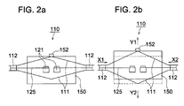
- Fig. 2a is a schematic diagram showing the front view of the situation of the pantograph section 110 wherein electric current is not applied to the SMA 125.
- Fig. 2b is a schematic diagram showing the front view of the situation of the pantograph section 110 wherein electric current is applied to the SMA 125.
- the pantograph section 110 includes two sheet-like drive arms 111 provided on the upper and lower portions and two spacers 112 sandwiched between the two drive arms 111.
- the spacer 112 is made of polyimide, for example.
- the SMA 125 contracts, whereby two spacers 112 are pulled in the arrow-marked directions X1 and X2, respectively, and are moved inwardly.
- two drive arms 111 bend in the arrow-marked directions Y1 and Y2, respectively.
- the lens barrel 150 held by the drive arm 111 through the hook sections 152 is pushed up and is moved to the arrow-marked direction Y1.
- the lens barrel is driven by power on/off control of the SMA 125, as shown above.
- Fig. 3a is a schematic diagram showing the front view of an example of the shape of the caulking portion of the SMA fixing member 121.
- Figs. 3b through 3d are schematic diagrams of the front view showing the shape in other examples of the caulking portion of the SMA fixing member 121.
- Figs. 3e and 3f are the schematic diagrams showing the shape in other examples of the caulking portion of the SMA fixing member 121, as viewed obliquely from the forward position on the front.
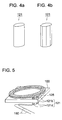
- Fig. 4a is a schematic diagram showing the perspective view of the shape of an example of the SMA fixing member 121.
- Fig. 4b is a schematic diagram showing the perspective view of the shape of another example of the SMA fixing member 121.
- a V-shaped groove 121v is formed around the side surface of the SMA fixing member 121, and the SMA 125 is pinch-held in this groove 121v.
- the end portion 121b as the caulking portion of the SMA fixing member 121 is deformed and the SMA 125 is fixed by pressure contact (caulking).
- the diameter d1 of the end portion 121b is made smaller than the diameter d2 of the non-deformation portion 121c.
- the SMA fixing member 121 when the SMA fixing member 121 is press-fit into the base member 100, deformation may occur if the end portion 121b of the SMA fixing member 121 is pushed. Accordingly, the non-deformation portion 121c is pushed into the base member 100 for press-fitting. In this case as well, the diameter d1 of the end portion 121b is smaller than the diameter d2 of the non-deformation portion 121c to ensure that the end portion 121b will not be caught by the press-fit hole of the base member 100.
- Fig. 3b shows the shape of another example of the caulking portion.
- the v-shaped groove 121v can be arranged in a part of the side surface of the end portion 121b of the SMA fixing member 121.
- Fig. 3c shows the shape of still another example of the caulking portion.
- the groove 121v can be arranged on the end face 121a of the SMA fixing member 121.
- the end portion 121b of the SMA fixing member 121 is caulked by the pressure applied in the direction Y2 with a caulking jig 5, shown in Fig. 3c , with a taper 5a formed on the inner surface.
- a taper 121t can be formed on the end portion 121b of the SMA fixing member 121. This will avoid catching of the end portion 121b when the SMA fixing member 121 is pushed into the base member 100 to be fixed.
- Fig. 3e shows the shape of a further example of the caulking portion.
- two grooves 121v can be arranged in the shape of a cross on the end face 121a of the SMA fixing member 121. This increases the degree of freedom in the direction of rotation when the SMA fixing member 121 is pushed into the base member 100.
- the taper 121t can be formed on the end portion 121b of the SMA fixing member 121. This will avoid catching of the end portion 121b when the SMA fixing member 121 is pushed into the base member 100 to be fixed.
- Any of the shapes shown in Figs. 3a through 3f can be easily formed by the well known machining operation.
- the SMA fixing member 121 has a cross section of a circular shape or a polygonal shape. If the groove 121v is formed around the side surface of the SMA fixing member 121 as shown in Fig. 3a , there is no need of taking the rotational direction into account when the SMA fixing member 121 is fixed onto the base member 100.
- the SMA fixing member 121 is preferably formed in a cylinder, as shown in Fig. 4a .
- the groove 121v is formed in a doglegged shape on a part of the side surface of the SMA fixing member 121, as shown in Fig.
- the SMA fixing member 121 is preferably formed in a polyangular prismatic shape, which has directionality, as shown in Fig. 4b .
- the SMA fixing member 121 shown in Fig. 4b is octangular prismatic as an, for example, but the present invention is not restricted thereto. It can be shaped in an N-angular prismatic shape (wherein N is a positive integer) or D-cut formed.
- the SMA fixing member 121 is preferably made of SUS steel or copper-family metal material having a Young's modulus of not less than 50 and not more than 250 GPa, with consideration given to the holding force and caulking pressure. Further, such a metal material can be adjusted to have a desired Young's modulus by controlling the percentage of alloy components, the volume of additives used, or heat treatment. In case of the SUS steel, adjustment can be made by controlling the percentage of alloy components or heat treatment so that the SUS steel is in optimum conditions for caulking. Further, the copper-family metal in the sense in which it is used here refers to the alloy mainly composed of copper or to pure copper.
- the surface of the SUS steel is preferably provided with nickel plating to improve the efficiency of soldering the power-feeding members such as a lead wire or a flexible printed circuit board for applying electric current to the SMA 125.
- a single rod-like member namely, the SMA fixing member 121 is used for two purposes of fixing the SMA 125 and connecting with the power-feeding member for supplying current to the SMA 125, and the SMA fixing member 121 is fixed by penetrating the base member 110.
- This arrangement allows the SMA fixing member 121 to be installed in a small space whose area is equal to the area of the cross section in the radial direction, whereby downsizing of the apparatus is achieved.
- Fig. 5 is a schematic diagram showing a method of connecting between the SMA fixing members 121 and the lead wires 180.
- the lead wires 180 are soldered onto the end portion 121d (the electrical connection portion of the present invention) which is on the side opposite to the caulking portion 121b of the SMA fixing member 121with the base member 100 in-between.
- the distance between the caulking portion 121b on which the SMA 125 is fixed by pressure contact and the end portion 121d to which the lead wire 180 is soldered can be not less than at least the thickness of the base member 100. Heat is also released to the base member 100. This arrangement reduces the transmission of heat to the SMA 125 at the time of soldering, and minimizes the possible deterioration in the performance of the SMA 125.
- the base member 100 is required to have a strength for stable holding of the lens barrel 150, and is formed to have a predetermined thickness to meet this requirement. Further, the base member 100 is made of a nonconducting material to avoid electric short-circuiting between two SMA fixing members 121 to be connected with the power-feeding members. If the base member 100 is made of a conducting material, insulating treatment is provided between the base member 100 and the two SMA fixing members 121.
- the SMA fixing members 121 can be fixed onto the base member 100 (securing step) by the insert mold method wherein the SMA fixing members 121 are molded integrally with the base member 100. Alternatively, the SMA fixing members 121 are pushed into the holes to be fixed in position, the holes which are provided beforehand in the base member 100.
- the direction of the groove 121v should be determined in conformity to the direction of the SMA 125 to be mounted.
- the SMA fixing member 121 is formed to have directionality, as shown in Fig. 4 (b) , and the position of the groove 121v is determined in the direction of the SMA 125.
- the hole for press-fitting is designed to have a polygonal or D-cut form that allows the direction to be determined.
- Fig. 6 is a schematic diagram showing the method of extending the SMA 125.
- Fig. 7 is a schematic diagram showing how to caulk the SMA fixing member 121 with the SMA 125.
- the SMA 125 is locked on the two spacers 112 mounted on the pantograph section 110 and the tension guide 101 mounted on the base member 100, and is extended so that a predetermined tension is applied.
- the caulking portions 121b of the SMA fixing members 121 located on both sides of the extended SMA 125 are pressed by the pressure in the direction Y2 to caulk, and the SMA 125 is held to be sandwiched between the SMA fixing members 121 (caulking step).
- the SMA fixing member 121 Since the SMA fixing member 121 is fixed by penetrating the base member 100, the end face 121e opposite to the end face 121a used for caulking of the SMA fixing member 212 can be supported when caulking is executed. This arrangement allows the caulking force to be applied directly to the rod-like member without being applied through other members. This eliminates unstable factors in the caulking work. Thus, the SMA is securely fixed in position and stable production is ensured.
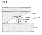
- Fig. 8 is a schematic diagram showing the relationship between the cut-in angle of the groove 121v and the static friction force between the SMA 125 and SMA fixing member 121.
- the cut-in angle of the caulking portion must be set to a proper value. The details will be described below.
- the friction force Q1 must be set at a level greater than the slip-out force P1.
- the cut-in angle ⁇ and static friction force ⁇ are required to satisfy the following relationship of Relationship 1: F ⁇ cos ⁇ ⁇ sin ⁇ ⁇ ⁇ ⁇ F ⁇ cos ⁇ ⁇ cos ⁇
- Relationship 2 is the result of simplifying the Relationship 1.
- the cut-in angle ⁇ is set at the value satisfying Relationship 2.
- the SMA 125 is controlled according to the principle that the resistance value of the SMA 125 has a linear relationship with the deformation value. To put it more specifically, the deformation value required to move the lens barrel 150 by a predetermined distance can be calculated from the overall length of the SMA 125. Thus, The resistance corresponding to the deformation value of the SMA 125 required to move the lens barrel 150 to a target position is calculated. This is followed by driving the lens barrel 150 by controlling the drive voltage of the SMA 125 so that the resistance value of the SMA 125 becomes the target resistance, whereby the lens barrel 150 is driven.
- Fig. 9 shows an example of a control system 10 of the lens driving device 1.
- the control system 10 includes a comparator section 201, control section 202, drive section 203 and resistance detecting section 204.
- the drive voltage of the SMA 125 is controlled so that the resistance value of the SMA 125 approaches the target resistance inputted from a camera body (not illustrated) or the like.
- the resistance detecting section 204 detects the resistance of the SMA 125 mounted on the lens driving device 1.
- the comparator section 201 compares between the resistance of the SMA 125 detected by the resistance detecting section 204 and the target resistance inputted from the camera body, whereby difference is calculated.
- the control section 202 calculates the drive voltage for the SMA 125 in conformity to the difference calculated by the resistance detecting section 204.
- the drive section 203 generates the drive voltage based on the drive voltage for the SMA 125 calculated by the control section 202, and applies it to the SMA 125.
- the SMA 125 is deformed by the drive voltage applied from the drive section 203 so that the lens barrel 150 is driven. This procedure is repeated until the difference calculated by the comparator section 201 is reduced to zero, whereby the lens barrel 150 is driven up to the target position.
- one rod-like member is used to fix the SMA thereto, and to connect with the power-feeding member for supplying electric current to the SMA.
- This rod-like member is fixed by penetrating the base member. This arrangement allows the rod-like member to be installed in a small space whose area is equal to the area of the cross section in the radial direction, whereby downsizing of the apparatus is achieved.
- the SMA is fixed onto one end of the rod-like member penetrating the base member, and power-feeding members were connected to the other end.
- a predetermined thickness is required to be thick enough to ensure that the base member is strong enough to hold the rod-like member penetrating the same. This arrangement prevents the performance of the SMA from being deteriorated, because when the conductive members are soldered onto the rod-like member, enough distance is secured to prevent the transmitted heat from affecting the performance of the SMA. This avoids the possible deterioration in the performance of the SMA.
- the rod-like member When pressure contact, namely, a caulking work of the rod-like member is conducted, the rod-like member can be supported at the end opposite to the end to be caulked, because the rod-like member extends through the base member to be fixed thereto.
- This arrangement allows the caulking force to be applied directly to the rod-like member without being applied through other members. This eliminates unstable factors in the caulking work.
- the SMA is securely fixed in position and stable production is ensured.
Landscapes
- Engineering & Computer Science (AREA)
- Chemical & Material Sciences (AREA)
- Combustion & Propulsion (AREA)
- Mechanical Engineering (AREA)
- General Engineering & Computer Science (AREA)
- Manufacturing & Machinery (AREA)
- Lens Barrels (AREA)
Abstract
Description
- This application is based on Japanese Patent Application No.
2007-112826 filed on April 23, 2007 - The present invention relates to a driving device and method of manufacturing the same, particularly to a driving device provided with a shape memory alloy and method of manufacturing the same.
- In recent years, attempts have been made to use as actuators various forms of driving devices provided with a shape memory alloy (hereinafter referred to as "SMA"). The SMA is typically represented by a titanium-nickel alloy. It has a property that even if the SMA is deformed at a temperature lower than the temperature called "transformation point", it goes back to the original state by martensite transformation when it is heated above that temperature. Normally, the SMA is made in the form of a string, and is expanded and contracted along the length by electricity-powered heat control, whereby the SMA can be used as an actuator.
- Such an SMA has a wire size as small as several tens of microns. This allows downsizing of an apparatus equipped with the SMA actuator. Thus, studies have been made to mount the SMA on various types of apparatuses.
- Incidentally, generally, such a string-like SMA is supported on a base member, which is provided on a frame or casing, through a fixing member to fix both ends thereof, and is extended to a driven member. Further, there is provided is on or around the fixing member an electrical connection terminal to which a lead wire or a flexible printed circuit board for applying electricity to the SMA is to be connected.
- For example, according to one of the techniques known in the conventional art, an SMA is pinch-held to be fixed by pressure contact in a pinching section formed by bending a plate-formed member. A lead wire for supplying electricity to the SMA is inserted between an annular washer member provided at the sandwiching section and the base member, and is secured by a screw (Unexamined Japanese Patent Application Publication No.
2006-189036 - In another known technique, an SMA is fixed by press-fitting together with a ball or wedge into the hole provided in a base member, and a lead wire for supplying electricity to the SMA is soldered onto the connection terminal arranged in the vicinity of the hole of the base member (Unexamined Japanese Patent Application Publication No.
2002-98911 - However, the technique disclosed in the Unexamined Japanese Patent Application Publication No.
2006-189036 - In the technique disclosed in the Unexamined Japanese Patent Application Publication No.
2002-98911 - An object of the present invention is to solve the aforementioned problems and to provide a driving device and method of manufacturing the driving device that ensure stable fixing of the SMA, without causing difficulties in downsizing the device, and without adversely affecting the performance of the SMA.
- In view of forgoing, one embodiment according to one aspect of the present invention is a driving device, comprising:
- a base member;
- a string-like shape memory alloy; and
- a rod-like member which is made of metal, extends through the base member and is secured to the base member; the rod-like member including:
- a caulking portion on a first end of the rod-like member by which the shape memory alloy is pinch-held; and
- an electrical connection portion on a second end of the rod-like member for supplying electricity to the shape memory alloy.
- According to another aspect of the present invention, another embodiment is a method of manufacturing a driving device, the method comprising the steps of:
- securing a rod-like metal member having a caulking portion on a first end thereof to a base member, the rod-like metal member extending through the base member with at least a part of the caulking portion protruded from the base member; and
- caulking the caulking portion to pinch-hold a string-like shape memory alloy,
-
-
Figs. 1a and 1b are external views of a lens driving device as an embodiment of the present invention; -
Figs. 2a and 2b are schematic diagrams representing the operation of the pantograph section; -
Figs. 3a, 3b, 3c, 3d, 3e and 3f are schematic diagrams representing the shape of the caulking portion of the SMA fixing member; -
Figs. 4a and 4b are schematic diagrams representing the shape of the SMA fixing member; -
Fig. 5 is a schematic diagram showing a method of connecting between the SMA fixing member and the lead wire; -
Fig. 6 is a schematic diagram showing a method of installing the SMA; -
Fig. 7 is a schematic diagram showing how to caulk the SMA fixing member with the SMA; -
Fig. 8 is a schematic diagram showing the cut-in angle of the caulking portion of the SMA fixing member; and -
Fig. 9 is a block diagram of the control system. - Referring to the drawings, the following describes the lens driving device of one of typical embodiments of driving devices according to an embodiment of the present invention. It should be noted that the present invention is not restricted thereto, although the present invention is described with reference to the illustrated embodiments.
- In the first place, the structure of the lens driving device will be explained with reference to
Figs. 1a and 1b. Fig. 1a is a plan view showing the external view of thelens driving device 1.Fig. 1b is a front view thereof. - As shown in
Fig. 1a , the major portions of thelens driving device 1 include abase member 100,pantograph section 110, SMAfixing member 121, SMA 125, andlens barrel 150. - As shown in
Fig. 1b , two rod-like metalSMA fixing members 121 are fixed in a form of penetrating thebase member 100. The SMA fixingmember 121 corresponds to the rod-like member of the present invention. - Both ends of the SMA 125 are fixed on the top end of the
SMA fixing member 121 by caulking. The details of the method of caulking of the SMA 125 will be described later. - The SMA 125, which has a string-like shape with a diameter of, for example, several tens of microns, is extended so as to be twisted around two string-
shaped spacers 112 provided on thepantograph section 110 and atension guide 101 provided on thebase member 100. - At the center of the
base member 100, alens barrel 150 equipped with a lens (not illustrated) is held on thepantograph section 110 byhook sections 152. Animage pickup element 151 such as a CCD (Charge Coupled Device) or CMOS sensor is provided under thelens barrel 150, wherein this image pickup element generates an image signal by photoelectric conversion of the optical image of a subject formed by the lens. - Referring to
Figs. 2a and 2b , the following describes the structure and operation of thepantograph section 110.Fig. 2a is a schematic diagram showing the front view of the situation of thepantograph section 110 wherein electric current is not applied to theSMA 125.Fig. 2b is a schematic diagram showing the front view of the situation of thepantograph section 110 wherein electric current is applied to theSMA 125. - As shown in
Fig. 2a , thepantograph section 110 includes two sheet-like drive arms 111 provided on the upper and lower portions and twospacers 112 sandwiched between the two drivearms 111. Thespacer 112 is made of polyimide, for example. - As shown in
Fig. 2b , when electric current is applied to theSMA 125, theSMA 125 contracts, whereby twospacers 112 are pulled in the arrow-marked directions X1 and X2, respectively, and are moved inwardly. As thespacer 112 moves inwardly, two drivearms 111 bend in the arrow-marked directions Y1 and Y2, respectively. Then thelens barrel 150 held by thedrive arm 111 through thehook sections 152 is pushed up and is moved to the arrow-marked direction Y1. Thus, the lens barrel is driven by power on/off control of theSMA 125, as shown above. - Referring to
Figs. 3a, 3b, 3c, 3d, 3e and 3f , andFigs. 4a and 4b , the following describes theSMA fixing member 121.Fig. 3a is a schematic diagram showing the front view of an example of the shape of the caulking portion of theSMA fixing member 121.Figs. 3b through 3d are schematic diagrams of the front view showing the shape in other examples of the caulking portion of theSMA fixing member 121.Figs. 3e and 3f are the schematic diagrams showing the shape in other examples of the caulking portion of theSMA fixing member 121, as viewed obliquely from the forward position on the front.Fig. 4a is a schematic diagram showing the perspective view of the shape of an example of theSMA fixing member 121.Fig. 4b is a schematic diagram showing the perspective view of the shape of another example of theSMA fixing member 121. - As shown in
Fig. 3a , a V-shapedgroove 121v is formed around the side surface of theSMA fixing member 121, and theSMA 125 is pinch-held in thisgroove 121v. When a load is applied to theend face 121a of theSMA fixing member 121 in the direction Y2, theend portion 121b as the caulking portion of theSMA fixing member 121 is deformed and theSMA 125 is fixed by pressure contact (caulking). To prevent theSMA 125 from being cut off when theend portion 121b deformed by caulking covers over anon-deformation portion 121c, the diameter d1 of theend portion 121b is made smaller than the diameter d2 of thenon-deformation portion 121c. As will be described later, when theSMA fixing member 121 is press-fit into thebase member 100, deformation may occur if theend portion 121b of theSMA fixing member 121 is pushed. Accordingly, thenon-deformation portion 121c is pushed into thebase member 100 for press-fitting. In this case as well, the diameter d1 of theend portion 121b is smaller than the diameter d2 of thenon-deformation portion 121c to ensure that theend portion 121b will not be caught by the press-fit hole of thebase member 100. -
Fig. 3b shows the shape of another example of the caulking portion. As shown inFig. 3b , the v-shapedgroove 121v can be arranged in a part of the side surface of theend portion 121b of theSMA fixing member 121. -
Fig. 3c shows the shape of still another example of the caulking portion. As shown inFig. 3c , thegroove 121v can be arranged on theend face 121a of theSMA fixing member 121. In this case, theend portion 121b of theSMA fixing member 121 is caulked by the pressure applied in the direction Y2 with acaulking jig 5, shown inFig. 3c , with ataper 5a formed on the inner surface. Further, as shown inFig. 3d , ataper 121t can be formed on theend portion 121b of theSMA fixing member 121. This will avoid catching of theend portion 121b when theSMA fixing member 121 is pushed into thebase member 100 to be fixed. -
Fig. 3e shows the shape of a further example of the caulking portion. As shown inFig. 3e , twogrooves 121v can be arranged in the shape of a cross on theend face 121a of theSMA fixing member 121. This increases the degree of freedom in the direction of rotation when theSMA fixing member 121 is pushed into thebase member 100. Further, as shown inFig. 3f , thetaper 121t can be formed on theend portion 121b of theSMA fixing member 121. This will avoid catching of theend portion 121b when theSMA fixing member 121 is pushed into thebase member 100 to be fixed. Any of the shapes shown inFigs. 3a through 3f can be easily formed by the well known machining operation. - As shown in
Figs. 4a and 4b , theSMA fixing member 121 has a cross section of a circular shape or a polygonal shape. If thegroove 121v is formed around the side surface of theSMA fixing member 121 as shown inFig. 3a , there is no need of taking the rotational direction into account when theSMA fixing member 121 is fixed onto thebase member 100. Thus, theSMA fixing member 121 is preferably formed in a cylinder, as shown inFig. 4a . In the meantime, when thegroove 121v is formed in a doglegged shape on a part of the side surface of theSMA fixing member 121, as shown inFig. 3b , direction must be taken into account when theSMA fixing member 121 is fixed onto thebase member 100. Thus, theSMA fixing member 121 is preferably formed in a polyangular prismatic shape, which has directionality, as shown inFig. 4b . TheSMA fixing member 121 shown inFig. 4b is octangular prismatic as an, for example, but the present invention is not restricted thereto. It can be shaped in an N-angular prismatic shape (wherein N is a positive integer) or D-cut formed. - Since the
SMA 125 is held in position by the elasticity of the caulkedSMA fixing member 121, theSMA fixing member 121 is preferably made of SUS steel or copper-family metal material having a Young's modulus of not less than 50 and not more than 250 GPa, with consideration given to the holding force and caulking pressure. Further, such a metal material can be adjusted to have a desired Young's modulus by controlling the percentage of alloy components, the volume of additives used, or heat treatment. In case of the SUS steel, adjustment can be made by controlling the percentage of alloy components or heat treatment so that the SUS steel is in optimum conditions for caulking. Further, the copper-family metal in the sense in which it is used here refers to the alloy mainly composed of copper or to pure copper. Similarly to the case of the SUS steel, adjustment can be made by controlling the percentage of alloy components or heat treatment so that the SUS steel is in the optimum conditions for caulking. It should be pointed out that the copper-family metal is characterized in that it is easily cut, and plating work is not needed because it can be directly soldered without additional surface treatment. This reduces the production cost. Further, when SUS steel is used for theSMA fixing member 121, as will be described later, the surface of the SUS steel is preferably provided with nickel plating to improve the efficiency of soldering the power-feeding members such as a lead wire or a flexible printed circuit board for applying electric current to theSMA 125. - As described above, a single rod-like member, namely, the
SMA fixing member 121 is used for two purposes of fixing theSMA 125 and connecting with the power-feeding member for supplying current to theSMA 125, and theSMA fixing member 121 is fixed by penetrating thebase member 110. This arrangement allows theSMA fixing member 121 to be installed in a small space whose area is equal to the area of the cross section in the radial direction, whereby downsizing of the apparatus is achieved. - Referring to
Fig. 5 , the following describes the procedure of connecting theSMA fixing member 121 to the power-feeding member such as a lead wire or a flexible printed circuit board for applying electric current to theSMA 125.Fig. 5 is a schematic diagram showing a method of connecting between theSMA fixing members 121 and thelead wires 180. - As shown in
Fig. 5 , thelead wires 180 are soldered onto theend portion 121d (the electrical connection portion of the present invention) which is on the side opposite to thecaulking portion 121b of the SMA fixing member 121with thebase member 100 in-between. In this case, the distance between thecaulking portion 121b on which theSMA 125 is fixed by pressure contact and theend portion 121d to which thelead wire 180 is soldered can be not less than at least the thickness of thebase member 100. Heat is also released to thebase member 100. This arrangement reduces the transmission of heat to theSMA 125 at the time of soldering, and minimizes the possible deterioration in the performance of theSMA 125. - The following describes the procedure of fixing the
SMA fixing member 121 onto thebase member 100. - The
base member 100 is required to have a strength for stable holding of thelens barrel 150, and is formed to have a predetermined thickness to meet this requirement. Further, thebase member 100 is made of a nonconducting material to avoid electric short-circuiting between twoSMA fixing members 121 to be connected with the power-feeding members. If thebase member 100 is made of a conducting material, insulating treatment is provided between thebase member 100 and the twoSMA fixing members 121. - The
SMA fixing members 121 can be fixed onto the base member 100 (securing step) by the insert mold method wherein theSMA fixing members 121 are molded integrally with thebase member 100. Alternatively, theSMA fixing members 121 are pushed into the holes to be fixed in position, the holes which are provided beforehand in thebase member 100. - As shown in
Fig. 3b , when the V-shapedgroove 121v of theSMA fixing member 121 is not axially symmetric and has directionality, the direction of thegroove 121v should be determined in conformity to the direction of theSMA 125 to be mounted. In this case, theSMA fixing member 121 is formed to have directionality, as shown inFig. 4 (b) , and the position of thegroove 121v is determined in the direction of theSMA 125. For example, in the case of insert mold method, there is provided in the die the shape by which the direction can be determined. Further, in the case of press-fitting, the hole for press-fitting is designed to have a polygonal or D-cut form that allows the direction to be determined. - Referring to
Figs. 6 and 7 , the following describes the procedure of caulking.Fig. 6 is a schematic diagram showing the method of extending theSMA 125.Fig. 7 is a schematic diagram showing how to caulk theSMA fixing member 121 with theSMA 125. - As shown in
Fig. 6 , theSMA 125 is locked on the twospacers 112 mounted on thepantograph section 110 and thetension guide 101 mounted on thebase member 100, and is extended so that a predetermined tension is applied. - As shown in
Fig. 7 , thecaulking portions 121b of theSMA fixing members 121 located on both sides of theextended SMA 125 are pressed by the pressure in the direction Y2 to caulk, and theSMA 125 is held to be sandwiched between the SMA fixing members 121 (caulking step). - Since the
SMA fixing member 121 is fixed by penetrating thebase member 100, theend face 121e opposite to theend face 121a used for caulking of the SMA fixing member 212 can be supported when caulking is executed. This arrangement allows the caulking force to be applied directly to the rod-like member without being applied through other members. This eliminates unstable factors in the caulking work. Thus, the SMA is securely fixed in position and stable production is ensured. - Referring to
Fig. 8 , the following describes the cut-in angle of the V-shapedgroove 121v formed in theSMA fixing member 121.Fig. 8 is a schematic diagram showing the relationship between the cut-in angle of thegroove 121v and the static friction force between theSMA 125 andSMA fixing member 121. - To prevent the
SMA 125 from slipping out of thegroove 121v at the time of caulking work, the cut-in angle of the caulking portion must be set to a proper value. The details will be described below. - Assume that caulking force is F, the cut-in angle of the
groove 121v is Θ, and the coefficient of static friction between theSMA 125 andSMA fixing member 121 is µ. The slip-out force P1 and friction force Q1 on the upper surface (slope) 121vU of thegroove 121v can be calculated by the followingFormulas 1 and 2 in conformity toFig. 8 :

- To prevent the
SMA 125 from slipping out of thegroove 121v, the friction force Q1 must be set at a level greater than the slip-out force P1. To be more specific, according to theFormulas 1 and 2, the cut-in angle Θ and static friction force µ are required to satisfy the following relationship of Relationship 1:
- Relationship 2 is the result of simplifying the
Relationship 1. The cut-in angle Θ is set at the value satisfying Relationship 2.
- The following describes how to drive the
lens driving device 1. TheSMA 125 is controlled according to the principle that the resistance value of theSMA 125 has a linear relationship with the deformation value. To put it more specifically, the deformation value required to move thelens barrel 150 by a predetermined distance can be calculated from the overall length of theSMA 125. Thus, The resistance corresponding to the deformation value of theSMA 125 required to move thelens barrel 150 to a target position is calculated. This is followed by driving thelens barrel 150 by controlling the drive voltage of theSMA 125 so that the resistance value of theSMA 125 becomes the target resistance, whereby thelens barrel 150 is driven. -
Fig. 9 shows an example of acontrol system 10 of thelens driving device 1. As shown inFig. 9 , thecontrol system 10 includes acomparator section 201,control section 202,drive section 203 andresistance detecting section 204. The drive voltage of theSMA 125 is controlled so that the resistance value of theSMA 125 approaches the target resistance inputted from a camera body (not illustrated) or the like. - In the first place, the
resistance detecting section 204 detects the resistance of theSMA 125 mounted on thelens driving device 1. Thecomparator section 201 compares between the resistance of theSMA 125 detected by theresistance detecting section 204 and the target resistance inputted from the camera body, whereby difference is calculated. Thecontrol section 202 calculates the drive voltage for theSMA 125 in conformity to the difference calculated by theresistance detecting section 204. Thedrive section 203 generates the drive voltage based on the drive voltage for theSMA 125 calculated by thecontrol section 202, and applies it to theSMA 125. TheSMA 125 is deformed by the drive voltage applied from thedrive section 203 so that thelens barrel 150 is driven. This procedure is repeated until the difference calculated by thecomparator section 201 is reduced to zero, whereby thelens barrel 150 is driven up to the target position. - According to the present embodiment, one rod-like member is used to fix the SMA thereto, and to connect with the power-feeding member for supplying electric current to the SMA. This rod-like member is fixed by penetrating the base member. This arrangement allows the rod-like member to be installed in a small space whose area is equal to the area of the cross section in the radial direction, whereby downsizing of the apparatus is achieved.
- Further, the SMA is fixed onto one end of the rod-like member penetrating the base member, and power-feeding members were connected to the other end. In this arrangement, a predetermined thickness is required to be thick enough to ensure that the base member is strong enough to hold the rod-like member penetrating the same. This arrangement prevents the performance of the SMA from being deteriorated, because when the conductive members are soldered onto the rod-like member, enough distance is secured to prevent the transmitted heat from affecting the performance of the SMA. This avoids the possible deterioration in the performance of the SMA.
- When pressure contact, namely, a caulking work of the rod-like member is conducted, the rod-like member can be supported at the end opposite to the end to be caulked, because the rod-like member extends through the base member to be fixed thereto. This arrangement allows the caulking force to be applied directly to the rod-like member without being applied through other members. This eliminates unstable factors in the caulking work. Thus, the SMA is securely fixed in position and stable production is ensured.
Claims (12)
- A driving device, comprising:a base member;a string-like shape memory alloy; anda rod-like member which is made of metal, extends through the base member and is secured to the base member; the rod-like member including:a caulking portion on a first end of the rod-like member by which the shape memory alloy is pinch-held; andan electrical connection portion on a second end of the rod-like member for supplying electricity to the shape memory alloy.
- The driving device of claim 1, wherein a whole part of the caulking portion is located within an imaginary extended side surface of the rod-like member.
- The driving device of claim 1 or 2, wherein the rod-like member is made of metal which has a Young's modulus of not less than 50 GPa and not greater than 250 GPa.
- The driving device of claim 3, wherein the rod-like member includes a cupper family metal.
- The driving device of claim 3, wherein the rod-like member includes an SUS steel.
- The driving device of anyone of the preceding claims, wherein the electrical connection portion is nickel plated.
- The driving device of anyone of the preceding claims, wherein the caulking portion is caulked in a longitudinal direction of the rod-like member.
- The driving device of anyone of the preceding claims 1 to 6, wherein the caulking portion is caulked in a radial direction of the rod-like member.
- The driving device of anyone of the preceding claims, wherein the rod-like member has a cross-section of a circular or polygonal shape.
- A method of manufacturing a driving device, the method comprising the steps of:securing a rod-like metal member having a caulking portion on a first end thereof to a base member, the rod-like metal member extending through the base member with at least a part of the caulking portion protruded from the base member; andcaulking the caulking portion to pinch-hold a string-like shape memory alloy,wherein a second end of the rod-like member functions as an electrical connection portion for supplying electricity to the shape memory alloy.
- The method of claim 10, wherein before the caulking portion is caulked, a cross-section of the caulking portion has a diameter smaller than a diameter of a cross-section of a portion of the rod-like member except the caulking portion.
- The method of claim 10 or 11, wherein the caulking portion includes a V-shaped groove to be suppressed by caulking, the shape memory alloy is to be pinch-held in the V-shaped groove by pressing the caulking portion with the shape memory alloy sandwiched in the V-shaped groove, and an angle Θ between inner surfaces of the V-shaped groove and a coefficient of static friction µ between the inner surface of the V-shaped groove and the shape memory alloy satisfy the following relationship:

Applications Claiming Priority (1)
| Application Number | Priority Date | Filing Date | Title |
|---|---|---|---|
| JP2007112826 | 2007-04-23 |
Publications (2)
| Publication Number | Publication Date |
|---|---|
| EP1985852A2 true EP1985852A2 (en) | 2008-10-29 |
| EP1985852A3 EP1985852A3 (en) | 2013-11-27 |
Family
ID=39563278
Family Applications (1)
| Application Number | Title | Priority Date | Filing Date |
|---|---|---|---|
| EP08007653.2A Withdrawn EP1985852A3 (en) | 2007-04-23 | 2008-04-18 | Driving device and method of manufacturing the same |
Country Status (3)
| Country | Link |
|---|---|
| US (1) | US7975477B2 (en) |
| EP (1) | EP1985852A3 (en) |
| JP (1) | JP4924519B2 (en) |
Families Citing this family (10)
| Publication number | Priority date | Publication date | Assignee | Title |
|---|---|---|---|---|
| KR20110081166A (en) * | 2008-10-02 | 2011-07-13 | 코니카 미놀타 옵토 인코포레이티드 | Driving device and imaging device |
| JP5245126B2 (en) * | 2009-03-03 | 2013-07-24 | コニカミノルタ株式会社 | Drive device |
| JP5211015B2 (en) * | 2009-11-04 | 2013-06-12 | 日立マクセル株式会社 | Imaging device |
| WO2012023605A1 (en) * | 2010-08-20 | 2012-02-23 | 株式会社青電舎 | Shock-driven actuator |
| JP6769602B2 (en) * | 2016-08-02 | 2020-10-14 | 株式会社テージーケー | Actuator |
| CN107942468B (en) * | 2017-11-13 | 2020-06-19 | 北京小米移动软件有限公司 | Image acquisition module and terminal |
| JP7061250B2 (en) * | 2019-01-29 | 2022-04-28 | 翌 中安 | Linear actuator |
| WO2021000162A1 (en) * | 2019-06-30 | 2021-01-07 | 瑞声光学解决方案私人有限公司 | Lens module |
| CN214540194U (en) * | 2021-03-12 | 2021-10-29 | 广东海德亚科技有限公司 | Lens module and electronic equipment |
| KR102609145B1 (en) * | 2021-09-07 | 2023-12-05 | 삼성전기주식회사 | Lens module and camera module including same |
Citations (3)
| Publication number | Priority date | Publication date | Assignee | Title |
|---|---|---|---|---|
| JP2002098911A (en) | 2000-09-22 | 2002-04-05 | Minolta Co Ltd | Apparatus using shape memory alloy cord and drive unit |
| JP2006189036A (en) | 2004-12-06 | 2006-07-20 | Konica Minolta Holdings Inc | Drive device |
| JP2007112826A (en) | 2005-10-18 | 2007-05-10 | Matsushita Electric Works Ltd | Resin composition, prepreg, laminate |
Family Cites Families (8)
| Publication number | Priority date | Publication date | Assignee | Title |
|---|---|---|---|---|
| JPS55146676A (en) * | 1979-04-27 | 1980-11-15 | Hitachi Ltd | Setter for beginning of tape |
| US4761955A (en) * | 1987-07-16 | 1988-08-09 | The Boeing Company | Rotary actuator utilizing a shape memory alloy |
| US5186420A (en) * | 1991-11-08 | 1993-02-16 | The United States Of America As Represented By The Secretary Of The Navy | Articulated fin/wing control system |
| US6006522A (en) * | 1998-08-10 | 1999-12-28 | Lockheed Martin Corporation | Translational actuator |
| JP2004076882A (en) * | 2002-08-20 | 2004-03-11 | Toki Corporation Kk | Alloy wire fastening method |
| EP1626177A1 (en) * | 2003-05-12 | 2006-02-15 | Mitsubishi Denki Kabushiki Kaisha | Drive device |
| JP2006267178A (en) * | 2005-03-22 | 2006-10-05 | Matsushita Electric Ind Co Ltd | Lens driving device and driving device |
| JP2007004121A (en) * | 2005-05-27 | 2007-01-11 | Konica Minolta Opto Inc | Motor, motor device and lens drive mechanism using the same |
-
2008
- 2008-04-14 JP JP2008104600A patent/JP4924519B2/en not_active Expired - Fee Related
- 2008-04-18 EP EP08007653.2A patent/EP1985852A3/en not_active Withdrawn
- 2008-04-18 US US12/105,571 patent/US7975477B2/en not_active Expired - Fee Related
Patent Citations (3)
| Publication number | Priority date | Publication date | Assignee | Title |
|---|---|---|---|---|
| JP2002098911A (en) | 2000-09-22 | 2002-04-05 | Minolta Co Ltd | Apparatus using shape memory alloy cord and drive unit |
| JP2006189036A (en) | 2004-12-06 | 2006-07-20 | Konica Minolta Holdings Inc | Drive device |
| JP2007112826A (en) | 2005-10-18 | 2007-05-10 | Matsushita Electric Works Ltd | Resin composition, prepreg, laminate |
Also Published As
| Publication number | Publication date |
|---|---|
| JP4924519B2 (en) | 2012-04-25 |
| EP1985852A3 (en) | 2013-11-27 |
| JP2008291834A (en) | 2008-12-04 |
| US7975477B2 (en) | 2011-07-12 |
| US20080256946A1 (en) | 2008-10-23 |
Similar Documents
| Publication | Publication Date | Title |
|---|---|---|
| EP1985852A2 (en) | Driving device and method of manufacturing the same | |
| CN103590989B (en) | Drive unit with and manufacture method | |
| JP5211015B2 (en) | Imaging device | |
| US8754950B2 (en) | Driving device and imaging device | |
| US8059346B2 (en) | Linear drive systems and methods thereof | |
| JP4956670B2 (en) | Electrical plug connector | |
| KR101765571B1 (en) | Driving device and structure of fixing the same | |
| US20090302708A1 (en) | Shape memory alloy actuator | |
| KR102468966B1 (en) | An electrical contact having a plurality of mating sections | |
| US8062080B2 (en) | Wedge connector assembly | |
| US10199750B2 (en) | Press-fit terminal | |
| KR102378010B1 (en) | Actuator | |
| CN1377450A (en) | Structure for electrically contacting a valve | |
| JP5245126B2 (en) | Drive device | |
| US7880349B2 (en) | Stator lead retainer device | |
| WO2011058609A1 (en) | Joint structure | |
| JP2010090709A (en) | Driving device | |
| EP3554201B1 (en) | Method and device for processing a radial electronic component | |
| JP4804814B2 (en) | Press-fit terminal | |
| KR101283705B1 (en) | Cameramodule piezoelectric autofocus actuator | |
| US20220190519A1 (en) | Electrical connector for a bus bar | |
| CN121382759A (en) | Spacing column and mounting method thereof | |
| JPH10150783A (en) | Piezoelectric actuator | |
| CN120320128A (en) | Connectors and car windshields | |
| JP2018034159A (en) | Conductive member made of two member |
Legal Events
| Date | Code | Title | Description |
|---|---|---|---|
| PUAI | Public reference made under article 153(3) epc to a published international application that has entered the european phase |
Free format text: ORIGINAL CODE: 0009012 |
|
| AK | Designated contracting states |
Kind code of ref document: A2 Designated state(s): AT BE BG CH CY CZ DE DK EE ES FI FR GB GR HR HU IE IS IT LI LT LU LV MC MT NL NO PL PT RO SE SI SK TR |
|
| AX | Request for extension of the european patent |
Extension state: AL BA MK RS |
|
| PUAL | Search report despatched |
Free format text: ORIGINAL CODE: 0009013 |
|
| AK | Designated contracting states |
Kind code of ref document: A3 Designated state(s): AT BE BG CH CY CZ DE DK EE ES FI FR GB GR HR HU IE IS IT LI LT LU LV MC MT NL NO PL PT RO SE SI SK TR |
|
| AX | Request for extension of the european patent |
Extension state: AL BA MK RS |
|
| RIC1 | Information provided on ipc code assigned before grant |
Ipc: F03G 7/06 20060101AFI20131021BHEP |
|
| AKY | No designation fees paid | ||
| REG | Reference to a national code |
Ref country code: DE Ref legal event code: R108 |
|
| REG | Reference to a national code |
Ref country code: DE Ref legal event code: R108 Effective date: 20140730 |
|
| STAA | Information on the status of an ep patent application or granted ep patent |
Free format text: STATUS: THE APPLICATION IS DEEMED TO BE WITHDRAWN |
|
| 18D | Application deemed to be withdrawn |
Effective date: 20140528 |