EP1985836A2 - Pressure regulator - Google Patents
Pressure regulator Download PDFInfo
- Publication number
- EP1985836A2 EP1985836A2 EP08151755A EP08151755A EP1985836A2 EP 1985836 A2 EP1985836 A2 EP 1985836A2 EP 08151755 A EP08151755 A EP 08151755A EP 08151755 A EP08151755 A EP 08151755A EP 1985836 A2 EP1985836 A2 EP 1985836A2
- Authority
- EP
- European Patent Office
- Prior art keywords
- pressure regulator
- pressure
- regulator according
- housing
- adjustment member
- Prior art date
- Legal status (The legal status is an assumption and is not a legal conclusion. Google has not performed a legal analysis and makes no representation as to the accuracy of the status listed.)
- Granted
Links
Images

Classifications
-
- F—MECHANICAL ENGINEERING; LIGHTING; HEATING; WEAPONS; BLASTING
- F02—COMBUSTION ENGINES; HOT-GAS OR COMBUSTION-PRODUCT ENGINE PLANTS
- F02M—SUPPLYING COMBUSTION ENGINES IN GENERAL WITH COMBUSTIBLE MIXTURES OR CONSTITUENTS THEREOF
- F02M37/00—Apparatus or systems for feeding liquid fuel from storage containers to carburettors or fuel-injection apparatus; Arrangements for purifying liquid fuel specially adapted for, or arranged on, internal-combustion engines
- F02M37/0011—Constructional details; Manufacturing or assembly of elements of fuel systems; Materials therefor
- F02M37/0023—Valves in the fuel supply and return system
- F02M37/0029—Pressure regulator in the low pressure fuel system
-
- G—PHYSICS
- G05—CONTROLLING; REGULATING
- G05D—SYSTEMS FOR CONTROLLING OR REGULATING NON-ELECTRIC VARIABLES
- G05D16/00—Control of fluid pressure
- G05D16/04—Control of fluid pressure without auxiliary power
- G05D16/10—Control of fluid pressure without auxiliary power the sensing element being a piston or plunger
- G05D16/103—Control of fluid pressure without auxiliary power the sensing element being a piston or plunger the sensing element placed between the inlet and outlet
Definitions
- the present invention relates to a pressure regulator, particularly, but not exclusively, a pressure regulator used to avoid overpressure in the fuel delivery system of an automobile.
- Pressure regulators which allow the activation pressure to be adjusted are known.
- An example of such a regulator is described in United States Patent No. 5,186, 147 .
- these adjustable regulators remain difficult to manufacture and install.
- the geometrical arrangement of such known regulators makes access and manipulation of the adjustment means difficult.
- Pressure actuated head member 14 rests within a correspondingly shaped seat 11 of the housing 12 and is also provided with an adjustment member 16.
- the adjustment member 16 and pressure actuated head member 14 are urged toward the seat 11 of the housing 12 due to a resilient force provided by the resilient member 18 which is buckled between the adjusting member 16 and a securing point 20 on the inside surface of the housing 12.
- the term “buckled” will be understood by the skilled reader to mean that the member is temporarily warped, bent or otherwise deformed from its otherwise normal shape in order to provide resilience. In other words, once buckled there is a tendency for the material of the resilient member 18 to return to it's original shape.
- the length of the partial though bore 30 and the adjustment member 16 are similar, such that when the adjustment member 16 sits within the partial though bore 16 its head is relatively flush with the outer surface of the semi-hemispherical head 14A of the head member 14 (although it will be appreciated that the relative flushness of the adjustment member and the outer surface of the semi-hemispherical head 14A will vary as the adjustment member is adjusted up and down the longitudinal axis L of the regulator 12).
- the cylindrical tail section 14B of the head member 14 in conjunction with the similarly shaped internal valve seat 11 of the regulator, ensures that the head member 14 does not tilt as it moves along the longitudinal axis L.
- An access window 22 is provided in the wall of the regulator housing 12 opposite the securing point 20. This provides access to the inner wall of the regulator housing 12 during manufacture to allow tooling of the securing point 20.
- a longitudinal ridge 24 protrudes from the inner wall of the regulator housing 12 opposite the access window 22.
- a detent 26 which terminates in a ledge (securing point 20) is formed on the longitudinal ridge 24.
- the internal bore of the regulator 12 is provided with a series of fluid communication passageways 32 spaced around the circumference of the head member 14.
- the fluid communication passageways extend longitudinally from the top (adjacent the intersection between the cylindrical tail section 14B and the semi-hemispherical head section 14A) and toward the bottom (adjacent the lower end of the cylindrical tail section 14B).
- Three longitudinal grooves 15 are also provided on the upper external wall of the regulator 12. These grooves 15 ensure a constant thickness is provided in the material (typically plastic) wall thereby providing an improved injection process.
- the head member 14 In use, when the bore pressure on one side of the regulator 10 (left hand side in Fig. 2 ) increases beyond a threshold pressure, the head member 14 will be urged toward the other side of the regulator 10. As the head member 14 moves it lifts from its seat 11 in the housing 12 thereby allowing fluid to flow between the resultant gap between the semi-hemispherical had member 14A and the seat 11, through the fluid communication passageways 32 and hence out through the bottom of the regulator 12.
- the closing force provided by the resilient member 18 can be easily adjusted by inserting a suitable tool into the tool socket 17 and rotating the adjustment member 16.
- the top of the hemispherical nose section 14A is provided with a transverse holding slot 31 adjacent the through bore 30 which allows the nose section 14A to be held against rotation as the adjustment member 16 is rotated.
- the closing force is related to the radius of curvature of the resilient member 18 such that rotating the adjustment member 16 alters the radius of curvature of the resilient member 18.
- the force provided by the resilient member 18 can be increased by screwing the adjusting member 16 further into the partial through bore 30 whereas if a relatively low maximum pressure is desired before the pressure regulator 10 will allow fluid to flow through it, the force provided by the resilient member 18 can be decreased by screwing the adjusting member 16 further out of the partial through bore 30.
Landscapes
- Engineering & Computer Science (AREA)
- Physics & Mathematics (AREA)
- Chemical & Material Sciences (AREA)
- Combustion & Propulsion (AREA)
- Mechanical Engineering (AREA)
- General Engineering & Computer Science (AREA)
- Fluid Mechanics (AREA)
- General Physics & Mathematics (AREA)
- Automation & Control Theory (AREA)
- Control Of Fluid Pressure (AREA)
Abstract
Description
- The present invention relates to a pressure regulator, particularly, but not exclusively, a pressure regulator used to avoid overpressure in the fuel delivery system of an automobile.
- Pressure regulators are used in a variety of applications. In general, although often part of a large and complicated system, the pressure regulator itself often performs essentially the same function regardless of the application. That is, it allows fluid to pass from a first zone to a second zone when the fluid pressure in the first zone is greater than a threshold predetermined maximum. With reference to
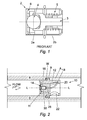
Fig. 1 , this can be achieved by providing a generallycylindrical housing 2 which encloses acup 3, ball 4 and coiled spring 5. The ball 4 sits in thecup 3 and the two together constitute a head member. The spring 5 serves as resilient means. Thecup 3 and ball 4 are held within thehousing 2 under the tension of the compressed spring 5 by acover 6 such that the ball covers an opening in one end of the housing. When fluid on the remote side of thehousing 2 to the ball 4 (left hand side ofFig. 1 ) reaches a threshold activation pressure, and the force on the ball exceeds the force exerted by the spring 5, the spring 5 will begin to compress thereby allowing thecup 3 and ball 4 to move (to the right hand side inFig. 1 ) in order to allow fluid to flow through the opening, into thehousing 2. The fluid will continue to flow into thehousing 2 until the pressure level drops below the threshold at which point the action of the spring 5 will return the ball 4 to the closed position. - A disadvantage of such arrangements is that the housing normally comprises a pair of sections (2a and 2b as shown in
Fig. 1 ) which are snap-fitted together during manufacture. This makes it difficult to provide any way of adjusting the regulator's activation pressure. Another disadvantage is that the coiled spring, ball and cup require relatively large components and are relatively difficult to manufacture. - Pressure regulators which allow the activation pressure to be adjusted are known. An example of such a regulator is described in United States Patent No.
5,186, 147 . However, typically, these adjustable regulators remain difficult to manufacture and install. Furthermore, the geometrical arrangement of such known regulators makes access and manipulation of the adjustment means difficult. - According to the present invention there is provided a pressure regulator comprising:
- a housing;
- a pressure actuated head member adapted to be actuable between an open and a closed position when a sufficient pressure differential across the housing is present;
an adjustment member provided on the pressure actuated head member, wherein the adjustment member is movable along the longitudinal axis of the pressure regulator; - resilient means for imparting a resilient force on the adjustment member thereby to urge the pressure actuated head member toward the closed position, wherein adjustment of the adjustment member varies the force exerted by the resilient means and thereby the force exerted on the head member.
- Preferred features and advantages of the invention will be apparent from the following description and the claims.
- Embodiments of the present invention will now be described, by way of example only, with reference to the accompanying drawings, in which:-
-
Fig. 1 is a transverse cross sectional view of a non-adjustable prior art regulator not in accordance with the present invention; -
Fig. 2 is a transverse cross sectional view of a pressure regulator according to the present invention, where the pressure regulator is installed in a nominal bore of a fuel delivery system; -
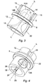
Fig. 3 is a partial cut-away perspective view of the pressure regulator according to the present invention where the head of the pressure regulator is in the closed position; -
Fig. 4 is a perspective view from the underside of the pressure regulator ofFig. 3 ; -
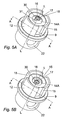
Fig. 5A is perspective view from the upper end of the pressure regulator where the head of the pressure regulator is in the closed position; -
Fig. 5B is perspective view from the upper end of the pressure regulator where the head of the pressure regulator is in the open position; -
Fig. 6 is a cut-away perspective illustration viewed along the line A-A ofFig. 5 ; and -
Fig. 7 is a perspective view from the underside of the pressure regulator ofFig. 3 , where the head of the pressure regulator is in the open position and the resilient member is buckled by a greater amount than that shown inFig. 4 . - Referring to
Fig. 2 , apressure regulator 10 has ahousing 12 installed in a nominal bore B in which the pressure is to be regulated. InFig. 2 , the upper end of thepressure regulator 10 is toward the left hand side of the bore B and the lower end toward the right hand side of the bore B such that the flow of fluid from a relatively high pressure zone (on the left of regulator 10) to a relatively low pressure zone (on the right of the regulator 10) is regulated. - A
sealing ridge 9 extends around the outer circumference of thehousing 12 in order to close an annulus A between thehousing 12 and the bore B. A washer W is provided on theridge 9 in order to provide a fluid tight seal there across. - Pressure actuated
head member 14 rests within a correspondingly shapedseat 11 of thehousing 12 and is also provided with anadjustment member 16. Theadjustment member 16 and pressure actuatedhead member 14 are urged toward theseat 11 of thehousing 12 due to a resilient force provided by theresilient member 18 which is buckled between the adjustingmember 16 and asecuring point 20 on the inside surface of thehousing 12. In this regard, the term "buckled" will be understood by the skilled reader to mean that the member is temporarily warped, bent or otherwise deformed from its otherwise normal shape in order to provide resilience. In other words, once buckled there is a tendency for the material of theresilient member 18 to return to it's original shape. - As seen in
Fig. 5A and Fig. 5B , atool socket 17 is provided in the top of theadjustment member 16. In the present embodiment the tool (not shown)socket 17 is shaped to receive an end of a hexagonal adjustment tool such as an Allen key, although it could alternatively be shaped to receive any suitable shape of tool. - The
resilient member 16 may be formed of any suitably resilient material. An example of a suitable resilient member is a strip of metal having a width and breadth that is substantially less than its length. Theresilient member 16 is restrained at its lower end by being wedged against the lip formed at securingpoint 20 and at its upper end by insertion into anorifice 28 in the rear of thecylindrical tail section 14B to engage the lower end surface of theadjustment member 16. This is best illustrated byFig. 6 . - The pressure actuated
head member 14 has asemi-hemispherical nose section 14A and acylindrical tail section 14B.Adjustment member 16 is positioned within an enlarged partial throughbore 30 in thenose section 14A of thehead member 14 and comprises a threaded screw (not shown) which co-operates with a corresponding screw thread (not shown) in the inner walls of the enlarged partial throughbore 30 such that rotation of theadjustment member 16 causes it to move up and down the longitudinal axis L of theregulator 10. As shown inFig. 2 ,5A and 5B , the length of the partial though bore 30 and theadjustment member 16 are similar, such that when theadjustment member 16 sits within the partial though bore 16 its head is relatively flush with the outer surface of thesemi-hemispherical head 14A of the head member 14 (although it will be appreciated that the relative flushness of the adjustment member and the outer surface of thesemi-hemispherical head 14A will vary as the adjustment member is adjusted up and down the longitudinal axis L of the regulator 12). In this regard, thecylindrical tail section 14B of thehead member 14, in conjunction with the similarly shapedinternal valve seat 11 of the regulator, ensures that thehead member 14 does not tilt as it moves along the longitudinal axis L. - An
access window 22 is provided in the wall of theregulator housing 12 opposite thesecuring point 20. This provides access to the inner wall of theregulator housing 12 during manufacture to allow tooling of thesecuring point 20. With particular reference toFigs. 4 and7 , alongitudinal ridge 24 protrudes from the inner wall of theregulator housing 12 opposite theaccess window 22. A detent 26 which terminates in a ledge (securing point 20) is formed on thelongitudinal ridge 24. - Referring to
Figs. 3 and6 , the internal bore of theregulator 12 is provided with a series offluid communication passageways 32 spaced around the circumference of thehead member 14. The fluid communication passageways extend longitudinally from the top (adjacent the intersection between thecylindrical tail section 14B and thesemi-hemispherical head section 14A) and toward the bottom (adjacent the lower end of thecylindrical tail section 14B). Threelongitudinal grooves 15 are also provided on the upper external wall of theregulator 12. Thesegrooves 15 ensure a constant thickness is provided in the material (typically plastic) wall thereby providing an improved injection process. - In use, when the bore pressure on one side of the regulator 10 (left hand side in
Fig. 2 ) increases beyond a threshold pressure, thehead member 14 will be urged toward the other side of theregulator 10. As thehead member 14 moves it lifts from itsseat 11 in thehousing 12 thereby allowing fluid to flow between the resultant gap between the semi-hemispherical hadmember 14A and theseat 11, through thefluid communication passageways 32 and hence out through the bottom of theregulator 12. - Once the overpressure has been released, the
resilient member 18, which by now will have been buckled further by thehead member 14, urges thehead member 14 back toward the closed position in order to prevent flow of fluid through the regulator. - In order to adjust the pressure at which the
regulator 12 will open to allow flow of fluid through, the closing force provided by theresilient member 18 can be easily adjusted by inserting a suitable tool into thetool socket 17 and rotating theadjustment member 16. In this regard, the top of thehemispherical nose section 14A is provided with atransverse holding slot 31 adjacent the throughbore 30 which allows thenose section 14A to be held against rotation as theadjustment member 16 is rotated. As seen in the figure, the closing force is related to the radius of curvature of theresilient member 18 such that rotating theadjustment member 16 alters the radius of curvature of theresilient member 18. Therefore if a relatively high maximum pressure is desired before thepressure regulator 10 will allow fluid to flow through it, the force provided by theresilient member 18 can be increased by screwing the adjustingmember 16 further into the partial throughbore 30 whereas if a relatively low maximum pressure is desired before thepressure regulator 10 will allow fluid to flow through it, the force provided by theresilient member 18 can be decreased by screwing the adjustingmember 16 further out of the partial throughbore 30. - Modifications and improvements may be made to the foregoing without departing from the scope of the invention.
Claims (14)
- A pressure regulator comprising:-a housing (12);a pressure actuated head member (14) having a partial through bore (30) therein and being actuable between an open and a closed position when a sufficient pressure differential across the housing (12) is present;an adjustment member (16) provided in the partial through bore (30) of the pressure actuated head member (14), wherein the adjustment member (16) is movable along the partial through bore (30) of the pressure actuated head member (14);resilient means (18) for imparting a resilient force on the adjustment member (16) thereby to urge the pressure actuated head member (14) toward the closed position, wherein adjustment of the adjustment member (14) along the partial through bore (30) varies the force exerted by the resilient means (18) and thereby the force exerted on the pressure actuated head member (14).
- A pressure regulator according to claim 1, wherein a securing point (20) is provided on the housing (12) to secure the resilient means (18) thereto.
- A pressure regulator according to claim 2, wherein the securing point (20) comprises a longitudinal ridge (24) protruding from an inner wall of the regulator housing (12), the longitudinal ridge (24) having a detent (26) which terminates in a ledge for receiving one end of the resilient means (18).
- A pressure regulator according to either of claims 2 or 3, wherein an access window (22) is provided through a wall of the regulator housing (12) opposite the securing point (20) in order to allow tooling of the securing point (20).
- A pressure regulator according to any of claims 2 to 4, wherein the resilient means comprises an elongate resilient member (18) positioned between the adjustment member (16) and the securing point (20) on the housing (12).
- A pressure regulator according to claim 5, wherein the elongate resilient member (18) is positioned between the adjustment member (16) and the securing point (20) of the housing (12) in a buckled state.
- A pressure regulator according to either of claims 5 or 6, wherein the resilient means (18) comprises a buckled strip of metal having a width and breadth that is substantially less than the strip's length.
- A pressure regulator according to any of claims 5 to 7, wherein the base of the head member (14) is provided with an orifice (28) to receive the top of the elongate resilient member (18) therethrough such that the top of the elongate resilient member (18) protrudes into the partial through bore (30) and abuts against the base of the adjustment member (16).
- A pressure regulator according to claim 8, wherein the adjustment member (16) comprises a threaded screw arrangement which when screwed in one direction causes the adjustment member (16) to pass into the partial through bore (30) thereby increasing the buckle of the resilient means (18) and when screwed in the opposite direction causes the adjustment member (16) to allow the buckle of the resilient means (18) to decrease.
- A pressure regulator according to claim 9, wherein the threaded screw arrangement is provided with a flush head capable of receiving a tool suitable for adjustment of the adjustment member (16).
- A pressure regulator according to any preceding claim, wherein the pressure actuated head member (14) comprises a rounded nose section (14A) and the regulator housing (12) comprises a correspondingly shaped seat (11) such that when the rounded nose section (14A) abuts against the correspondingly shaped seat (11), a substantially fluid-tight seal is created therebetween.
- A pressure regulator according to any preceding claim, wherein the pressure actuated head member (14) comprises a cylindrical tail section (14B).
- A pressure regulator according to claims 11 or 12, wherein at least a fluid communication passageway (32) is provided around the pressure actuated head member (14) such that when the pressure actuated head member moves from the seat (11), fluid may flow there along from one side of the pressure regulator to the other.
- A pressure regulator according to claim 13, wherein a plurality of fluid communication passageways (32) are spaced around the circumference of the cylindrical tail section (14B).
Priority Applications (1)
| Application Number | Priority Date | Filing Date | Title |
|---|---|---|---|
| EP08151755.9A EP1985836B1 (en) | 2007-04-24 | 2008-02-21 | Pressure regulator |
Applications Claiming Priority (2)
| Application Number | Priority Date | Filing Date | Title |
|---|---|---|---|
| EP07106807A EP1985835A1 (en) | 2007-04-24 | 2007-04-24 | Pressure regulator |
| EP08151755.9A EP1985836B1 (en) | 2007-04-24 | 2008-02-21 | Pressure regulator |
Publications (3)
| Publication Number | Publication Date |
|---|---|
| EP1985836A2 true EP1985836A2 (en) | 2008-10-29 |
| EP1985836A3 EP1985836A3 (en) | 2011-05-11 |
| EP1985836B1 EP1985836B1 (en) | 2014-09-10 |
Family
ID=38521646
Family Applications (2)
| Application Number | Title | Priority Date | Filing Date |
|---|---|---|---|
| EP07106807A Withdrawn EP1985835A1 (en) | 2007-04-24 | 2007-04-24 | Pressure regulator |
| EP08151755.9A Not-in-force EP1985836B1 (en) | 2007-04-24 | 2008-02-21 | Pressure regulator |
Family Applications Before (1)
| Application Number | Title | Priority Date | Filing Date |
|---|---|---|---|
| EP07106807A Withdrawn EP1985835A1 (en) | 2007-04-24 | 2007-04-24 | Pressure regulator |
Country Status (1)
| Country | Link |
|---|---|
| EP (2) | EP1985835A1 (en) |
Citations (2)
| Publication number | Priority date | Publication date | Assignee | Title |
|---|---|---|---|---|
| US5183074A (en) | 1991-09-30 | 1993-02-02 | Cla-Val Co. | Pressure-reducing valve, and aircraft fueling system incorporating the same |
| US5186147A (en) | 1991-04-09 | 1993-02-16 | Mallory, Inc. | Multi-port return type pressure regulator |
Family Cites Families (5)
| Publication number | Priority date | Publication date | Assignee | Title |
|---|---|---|---|---|
| US814285A (en) * | 1905-04-15 | 1906-03-06 | Edward E Gold | Pressure-regulator. |
| US2925824A (en) * | 1952-12-15 | 1960-02-23 | Edward A Rockwell | Fluid control valve |
| US4310142A (en) * | 1980-03-13 | 1982-01-12 | Tom Mcguane Industries, Inc. | Fuel pressure regulator assembly |
| US4543935A (en) * | 1984-08-21 | 1985-10-01 | Walbro Corporation | Pressure regulator with variable response |
| US5113831A (en) * | 1989-12-27 | 1992-05-19 | Barry Grant | Fuel pressure regulator |
-
2007
- 2007-04-24 EP EP07106807A patent/EP1985835A1/en not_active Withdrawn
-
2008
- 2008-02-21 EP EP08151755.9A patent/EP1985836B1/en not_active Not-in-force
Patent Citations (2)
| Publication number | Priority date | Publication date | Assignee | Title |
|---|---|---|---|---|
| US5186147A (en) | 1991-04-09 | 1993-02-16 | Mallory, Inc. | Multi-port return type pressure regulator |
| US5183074A (en) | 1991-09-30 | 1993-02-02 | Cla-Val Co. | Pressure-reducing valve, and aircraft fueling system incorporating the same |
Also Published As
| Publication number | Publication date |
|---|---|
| EP1985836A3 (en) | 2011-05-11 |
| EP1985835A1 (en) | 2008-10-29 |
| EP1985836B1 (en) | 2014-09-10 |
Similar Documents
| Publication | Publication Date | Title |
|---|---|---|
| US6554022B2 (en) | Regulator with improved seat | |
| US5518026A (en) | Filler neck butterfly check valve | |
| US20010032675A1 (en) | Bi-directional pressure relief valve | |
| US20100276623A1 (en) | Pressure control valve | |
| US3465787A (en) | Spring-biased valve with anti-chattering feature | |
| JPS62118170A (en) | Variable flow control valve | |
| US7165573B2 (en) | Compressed natural gas pressure regulator | |
| US3626975A (en) | Pressure relief valve | |
| CN109854428B (en) | Axial fluid pressure regulator | |
| EP3239628A1 (en) | Expansion valve | |
| US5137049A (en) | Pressure relief valve | |
| US5000222A (en) | Tamper resistant adjustment range control for the adjustment screw of a control device | |
| US3380474A (en) | Flap valve device | |
| US4611624A (en) | Line piercing valve assembly | |
| EP1985836B1 (en) | Pressure regulator | |
| EP1500855B1 (en) | Pressure control valve | |
| CN100472110C (en) | Built-in components for fitting into gas or liquid pipelines | |
| US5544855A (en) | Valve | |
| CN217272150U (en) | Split type enhanced damping type overflow valve | |
| US2945508A (en) | Pressure relief valve | |
| US20020047053A1 (en) | Pressure regulator | |
| US3958792A (en) | Valve with radially expansive valve plug | |
| US5407329A (en) | Pressure regulator for fuel injection devices | |
| EP0412861B1 (en) | Relief valve for hydraulic circuits | |
| CN219570470U (en) | Low-noise plug-in type overflow valve for hydraulic switch machine |
Legal Events
| Date | Code | Title | Description |
|---|---|---|---|
| PUAI | Public reference made under article 153(3) epc to a published international application that has entered the european phase |
Free format text: ORIGINAL CODE: 0009012 |
|
| AK | Designated contracting states |
Kind code of ref document: A2 Designated state(s): AT BE BG CH CY CZ DE DK EE ES FI FR GB GR HR HU IE IS IT LI LT LU LV MC MT NL NO PL PT RO SE SI SK TR |
|
| AX | Request for extension of the european patent |
Extension state: AL BA MK RS |
|
| PUAL | Search report despatched |
Free format text: ORIGINAL CODE: 0009013 |
|
| AK | Designated contracting states |
Kind code of ref document: A3 Designated state(s): AT BE BG CH CY CZ DE DK EE ES FI FR GB GR HR HU IE IS IT LI LT LU LV MC MT NL NO PL PT RO SE SI SK TR |
|
| AX | Request for extension of the european patent |
Extension state: AL BA MK RS |
|
| 17P | Request for examination filed |
Effective date: 20111111 |
|
| AKX | Designation fees paid |
Designated state(s): AT BE BG CH CY CZ DE DK EE ES FI FR GB GR HR HU IE IS IT LI LT LU LV MC MT NL NO PL PT RO SE SI SK TR |
|
| GRAP | Despatch of communication of intention to grant a patent |
Free format text: ORIGINAL CODE: EPIDOSNIGR1 |
|
| INTG | Intention to grant announced |
Effective date: 20140128 |
|
| GRAS | Grant fee paid |
Free format text: ORIGINAL CODE: EPIDOSNIGR3 |
|
| GRAA | (expected) grant |
Free format text: ORIGINAL CODE: 0009210 |
|
| AK | Designated contracting states |
Kind code of ref document: B1 Designated state(s): AT BE BG CH CY CZ DE DK EE ES FI FR GB GR HR HU IE IS IT LI LT LU LV MC MT NL NO PL PT RO SE SI SK TR |
|
| REG | Reference to a national code |
Ref country code: GB Ref legal event code: FG4D |
|
| REG | Reference to a national code |
Ref country code: CH Ref legal event code: EP |
|
| REG | Reference to a national code |
Ref country code: IE Ref legal event code: FG4D |
|
| REG | Reference to a national code |
Ref country code: AT Ref legal event code: REF Ref document number: 686826 Country of ref document: AT Kind code of ref document: T Effective date: 20141015 |
|
| REG | Reference to a national code |
Ref country code: DE Ref legal event code: R096 Ref document number: 602008034302 Country of ref document: DE Effective date: 20141023 |
|
| PG25 | Lapsed in a contracting state [announced via postgrant information from national office to epo] |
Ref country code: FI Free format text: LAPSE BECAUSE OF FAILURE TO SUBMIT A TRANSLATION OF THE DESCRIPTION OR TO PAY THE FEE WITHIN THE PRESCRIBED TIME-LIMIT Effective date: 20140910 Ref country code: NO Free format text: LAPSE BECAUSE OF FAILURE TO SUBMIT A TRANSLATION OF THE DESCRIPTION OR TO PAY THE FEE WITHIN THE PRESCRIBED TIME-LIMIT Effective date: 20141210 Ref country code: GR Free format text: LAPSE BECAUSE OF FAILURE TO SUBMIT A TRANSLATION OF THE DESCRIPTION OR TO PAY THE FEE WITHIN THE PRESCRIBED TIME-LIMIT Effective date: 20141211 Ref country code: LT Free format text: LAPSE BECAUSE OF FAILURE TO SUBMIT A TRANSLATION OF THE DESCRIPTION OR TO PAY THE FEE WITHIN THE PRESCRIBED TIME-LIMIT Effective date: 20140910 Ref country code: ES Free format text: LAPSE BECAUSE OF FAILURE TO SUBMIT A TRANSLATION OF THE DESCRIPTION OR TO PAY THE FEE WITHIN THE PRESCRIBED TIME-LIMIT Effective date: 20140910 Ref country code: SE Free format text: LAPSE BECAUSE OF FAILURE TO SUBMIT A TRANSLATION OF THE DESCRIPTION OR TO PAY THE FEE WITHIN THE PRESCRIBED TIME-LIMIT Effective date: 20140910 |
|
| REG | Reference to a national code |
Ref country code: NL Ref legal event code: VDEP Effective date: 20140910 |
|
| REG | Reference to a national code |
Ref country code: FR Ref legal event code: PLFP Year of fee payment: 8 |
|
| REG | Reference to a national code |
Ref country code: LT Ref legal event code: MG4D |
|
| PG25 | Lapsed in a contracting state [announced via postgrant information from national office to epo] |
Ref country code: HR Free format text: LAPSE BECAUSE OF FAILURE TO SUBMIT A TRANSLATION OF THE DESCRIPTION OR TO PAY THE FEE WITHIN THE PRESCRIBED TIME-LIMIT Effective date: 20140910 Ref country code: CY Free format text: LAPSE BECAUSE OF FAILURE TO SUBMIT A TRANSLATION OF THE DESCRIPTION OR TO PAY THE FEE WITHIN THE PRESCRIBED TIME-LIMIT Effective date: 20140910 Ref country code: LV Free format text: LAPSE BECAUSE OF FAILURE TO SUBMIT A TRANSLATION OF THE DESCRIPTION OR TO PAY THE FEE WITHIN THE PRESCRIBED TIME-LIMIT Effective date: 20140910 |
|
| REG | Reference to a national code |
Ref country code: AT Ref legal event code: MK05 Ref document number: 686826 Country of ref document: AT Kind code of ref document: T Effective date: 20140910 |
|
| PG25 | Lapsed in a contracting state [announced via postgrant information from national office to epo] |
Ref country code: NL Free format text: LAPSE BECAUSE OF FAILURE TO SUBMIT A TRANSLATION OF THE DESCRIPTION OR TO PAY THE FEE WITHIN THE PRESCRIBED TIME-LIMIT Effective date: 20140910 |
|
| PG25 | Lapsed in a contracting state [announced via postgrant information from national office to epo] |
Ref country code: SK Free format text: LAPSE BECAUSE OF FAILURE TO SUBMIT A TRANSLATION OF THE DESCRIPTION OR TO PAY THE FEE WITHIN THE PRESCRIBED TIME-LIMIT Effective date: 20140910 Ref country code: CZ Free format text: LAPSE BECAUSE OF FAILURE TO SUBMIT A TRANSLATION OF THE DESCRIPTION OR TO PAY THE FEE WITHIN THE PRESCRIBED TIME-LIMIT Effective date: 20140910 Ref country code: PT Free format text: LAPSE BECAUSE OF FAILURE TO SUBMIT A TRANSLATION OF THE DESCRIPTION OR TO PAY THE FEE WITHIN THE PRESCRIBED TIME-LIMIT Effective date: 20150112 Ref country code: IS Free format text: LAPSE BECAUSE OF FAILURE TO SUBMIT A TRANSLATION OF THE DESCRIPTION OR TO PAY THE FEE WITHIN THE PRESCRIBED TIME-LIMIT Effective date: 20150110 Ref country code: RO Free format text: LAPSE BECAUSE OF FAILURE TO SUBMIT A TRANSLATION OF THE DESCRIPTION OR TO PAY THE FEE WITHIN THE PRESCRIBED TIME-LIMIT Effective date: 20140910 Ref country code: EE Free format text: LAPSE BECAUSE OF FAILURE TO SUBMIT A TRANSLATION OF THE DESCRIPTION OR TO PAY THE FEE WITHIN THE PRESCRIBED TIME-LIMIT Effective date: 20140910 |
|
| PG25 | Lapsed in a contracting state [announced via postgrant information from national office to epo] |
Ref country code: PL Free format text: LAPSE BECAUSE OF FAILURE TO SUBMIT A TRANSLATION OF THE DESCRIPTION OR TO PAY THE FEE WITHIN THE PRESCRIBED TIME-LIMIT Effective date: 20140910 Ref country code: AT Free format text: LAPSE BECAUSE OF FAILURE TO SUBMIT A TRANSLATION OF THE DESCRIPTION OR TO PAY THE FEE WITHIN THE PRESCRIBED TIME-LIMIT Effective date: 20140910 |
|
| REG | Reference to a national code |
Ref country code: DE Ref legal event code: R097 Ref document number: 602008034302 Country of ref document: DE |
|
| PG25 | Lapsed in a contracting state [announced via postgrant information from national office to epo] |
Ref country code: BE Free format text: LAPSE BECAUSE OF NON-PAYMENT OF DUE FEES Effective date: 20150228 |
|
| PLBE | No opposition filed within time limit |
Free format text: ORIGINAL CODE: 0009261 |
|
| STAA | Information on the status of an ep patent application or granted ep patent |
Free format text: STATUS: NO OPPOSITION FILED WITHIN TIME LIMIT |
|
| PG25 | Lapsed in a contracting state [announced via postgrant information from national office to epo] |
Ref country code: DK Free format text: LAPSE BECAUSE OF FAILURE TO SUBMIT A TRANSLATION OF THE DESCRIPTION OR TO PAY THE FEE WITHIN THE PRESCRIBED TIME-LIMIT Effective date: 20140910 |
|
| 26N | No opposition filed |
Effective date: 20150611 |
|
| PG25 | Lapsed in a contracting state [announced via postgrant information from national office to epo] |
Ref country code: IT Free format text: LAPSE BECAUSE OF FAILURE TO SUBMIT A TRANSLATION OF THE DESCRIPTION OR TO PAY THE FEE WITHIN THE PRESCRIBED TIME-LIMIT Effective date: 20140910 |
|
| PG25 | Lapsed in a contracting state [announced via postgrant information from national office to epo] |
Ref country code: LU Free format text: LAPSE BECAUSE OF FAILURE TO SUBMIT A TRANSLATION OF THE DESCRIPTION OR TO PAY THE FEE WITHIN THE PRESCRIBED TIME-LIMIT Effective date: 20150221 |
|
| REG | Reference to a national code |
Ref country code: CH Ref legal event code: PL |
|
| GBPC | Gb: european patent ceased through non-payment of renewal fee |
Effective date: 20150221 |
|
| PG25 | Lapsed in a contracting state [announced via postgrant information from national office to epo] |
Ref country code: LI Free format text: LAPSE BECAUSE OF NON-PAYMENT OF DUE FEES Effective date: 20150228 Ref country code: MC Free format text: LAPSE BECAUSE OF FAILURE TO SUBMIT A TRANSLATION OF THE DESCRIPTION OR TO PAY THE FEE WITHIN THE PRESCRIBED TIME-LIMIT Effective date: 20140910 Ref country code: CH Free format text: LAPSE BECAUSE OF NON-PAYMENT OF DUE FEES Effective date: 20150228 |
|
| REG | Reference to a national code |
Ref country code: IE Ref legal event code: MM4A |
|
| PG25 | Lapsed in a contracting state [announced via postgrant information from national office to epo] |
Ref country code: SI Free format text: LAPSE BECAUSE OF FAILURE TO SUBMIT A TRANSLATION OF THE DESCRIPTION OR TO PAY THE FEE WITHIN THE PRESCRIBED TIME-LIMIT Effective date: 20140910 |
|
| PG25 | Lapsed in a contracting state [announced via postgrant information from national office to epo] |
Ref country code: IE Free format text: LAPSE BECAUSE OF NON-PAYMENT OF DUE FEES Effective date: 20150221 Ref country code: GB Free format text: LAPSE BECAUSE OF NON-PAYMENT OF DUE FEES Effective date: 20150221 |
|
| REG | Reference to a national code |
Ref country code: FR Ref legal event code: PLFP Year of fee payment: 9 |
|
| PGFP | Annual fee paid to national office [announced via postgrant information from national office to epo] |
Ref country code: DE Payment date: 20160226 Year of fee payment: 9 |
|
| PGFP | Annual fee paid to national office [announced via postgrant information from national office to epo] |
Ref country code: FR Payment date: 20160217 Year of fee payment: 9 |
|
| PG25 | Lapsed in a contracting state [announced via postgrant information from national office to epo] |
Ref country code: BE Free format text: LAPSE BECAUSE OF FAILURE TO SUBMIT A TRANSLATION OF THE DESCRIPTION OR TO PAY THE FEE WITHIN THE PRESCRIBED TIME-LIMIT Effective date: 20140910 |
|
| PG25 | Lapsed in a contracting state [announced via postgrant information from national office to epo] |
Ref country code: MT Free format text: LAPSE BECAUSE OF FAILURE TO SUBMIT A TRANSLATION OF THE DESCRIPTION OR TO PAY THE FEE WITHIN THE PRESCRIBED TIME-LIMIT Effective date: 20140910 |
|
| PG25 | Lapsed in a contracting state [announced via postgrant information from national office to epo] |
Ref country code: HU Free format text: LAPSE BECAUSE OF FAILURE TO SUBMIT A TRANSLATION OF THE DESCRIPTION OR TO PAY THE FEE WITHIN THE PRESCRIBED TIME-LIMIT; INVALID AB INITIO Effective date: 20080221 Ref country code: BG Free format text: LAPSE BECAUSE OF FAILURE TO SUBMIT A TRANSLATION OF THE DESCRIPTION OR TO PAY THE FEE WITHIN THE PRESCRIBED TIME-LIMIT Effective date: 20140910 |
|
| PG25 | Lapsed in a contracting state [announced via postgrant information from national office to epo] |
Ref country code: TR Free format text: LAPSE BECAUSE OF FAILURE TO SUBMIT A TRANSLATION OF THE DESCRIPTION OR TO PAY THE FEE WITHIN THE PRESCRIBED TIME-LIMIT Effective date: 20140910 |
|
| REG | Reference to a national code |
Ref country code: DE Ref legal event code: R119 Ref document number: 602008034302 Country of ref document: DE |
|
| REG | Reference to a national code |
Ref country code: FR Ref legal event code: ST Effective date: 20171031 |
|
| PG25 | Lapsed in a contracting state [announced via postgrant information from national office to epo] |
Ref country code: FR Free format text: LAPSE BECAUSE OF NON-PAYMENT OF DUE FEES Effective date: 20170228 Ref country code: DE Free format text: LAPSE BECAUSE OF NON-PAYMENT OF DUE FEES Effective date: 20170901 |