EP1985545A2 - Article carrier for fragile articles and corresponding blank - Google Patents
Article carrier for fragile articles and corresponding blank Download PDFInfo
- Publication number
- EP1985545A2 EP1985545A2 EP08160606A EP08160606A EP1985545A2 EP 1985545 A2 EP1985545 A2 EP 1985545A2 EP 08160606 A EP08160606 A EP 08160606A EP 08160606 A EP08160606 A EP 08160606A EP 1985545 A2 EP1985545 A2 EP 1985545A2
- Authority
- EP
- European Patent Office
- Prior art keywords
- panels
- tubular structure
- side wall
- article
- cushion member
- Prior art date
- Legal status (The legal status is an assumption and is not a legal conclusion. Google has not performed a legal analysis and makes no representation as to the accuracy of the status listed.)
- Withdrawn
Links
- 230000003019 stabilising effect Effects 0.000 claims abstract description 18
- 239000003292 glue Substances 0.000 claims description 29
- 229910003460 diamond Inorganic materials 0.000 claims description 4
- 239000010432 diamond Substances 0.000 claims description 4
- 239000011087 paperboard Substances 0.000 description 5
- 239000000463 material Substances 0.000 description 4
- 238000004026 adhesive bonding Methods 0.000 description 2
- 238000010276 construction Methods 0.000 description 2
- 238000000034 method Methods 0.000 description 2
- 238000004806 packaging method and process Methods 0.000 description 2
- 239000000969 carrier Substances 0.000 description 1
- 238000004519 manufacturing process Methods 0.000 description 1
- 239000002304 perfume Substances 0.000 description 1
- 230000000087 stabilizing effect Effects 0.000 description 1
Images



Classifications
-
- B—PERFORMING OPERATIONS; TRANSPORTING
- B65—CONVEYING; PACKING; STORING; HANDLING THIN OR FILAMENTARY MATERIAL
- B65D—CONTAINERS FOR STORAGE OR TRANSPORT OF ARTICLES OR MATERIALS, e.g. BAGS, BARRELS, BOTTLES, BOXES, CANS, CARTONS, CRATES, DRUMS, JARS, TANKS, HOPPERS, FORWARDING CONTAINERS; ACCESSORIES, CLOSURES, OR FITTINGS THEREFOR; PACKAGING ELEMENTS; PACKAGES
- B65D5/00—Rigid or semi-rigid containers of polygonal cross-section, e.g. boxes, cartons or trays, formed by folding or erecting one or more blanks made of paper
- B65D5/42—Details of containers or of foldable or erectable container blanks
- B65D5/44—Integral, inserted or attached portions forming internal or external fittings
- B65D5/50—Internal supporting or protecting elements for contents
- B65D5/5028—Elements formed separately from the container body
- B65D5/5035—Paper elements
- B65D5/5045—Tubular lining and supporting elements
-
- B—PERFORMING OPERATIONS; TRANSPORTING
- B65—CONVEYING; PACKING; STORING; HANDLING THIN OR FILAMENTARY MATERIAL
- B65D—CONTAINERS FOR STORAGE OR TRANSPORT OF ARTICLES OR MATERIALS, e.g. BAGS, BARRELS, BOTTLES, BOXES, CANS, CARTONS, CRATES, DRUMS, JARS, TANKS, HOPPERS, FORWARDING CONTAINERS; ACCESSORIES, CLOSURES, OR FITTINGS THEREFOR; PACKAGING ELEMENTS; PACKAGES
- B65D5/00—Rigid or semi-rigid containers of polygonal cross-section, e.g. boxes, cartons or trays, formed by folding or erecting one or more blanks made of paper
- B65D5/42—Details of containers or of foldable or erectable container blanks
- B65D5/44—Integral, inserted or attached portions forming internal or external fittings
- B65D5/50—Internal supporting or protecting elements for contents
- B65D5/5002—Integral elements for containers having tubular body walls
- B65D5/5007—Integral elements for containers having tubular body walls formed by inwardly protruding of folded parts of the body
Definitions
- the present invention relates to a carton and carton blank for forming the cartons. More particularly, the invention relates to a carton and blank for packaging fragile articles such as bottles of perfume for example.
- the present invention and its preferred embodiments seek to overcome or at least mitigate the problems of the prior art.
- One aspect of the invention provides a receptacle for packaging fragile articles comprising a plurality of side wall panels hinged together to form a collapsible upright tubular structure for receiving an article and an article support structure at the lower end of the tubular structure for supporting the article, wherein the support structure comprises a plurality of displaceable strips secured together such that when the tubular structure is erected from a flap collapsed form, the displaceable strips are automatically displaced into the tubular structure to form a supporting means.
- at least one of the displaceable strips may be provided along its upper edge with a foldable flap for providing a platform for the article.
- each pair having a respective displaceable strip wherein the displaceable strips are partially connected.
- the displaceable strips may be partially connected along a common lower edge.
- the support structure may further comprise a pair of glue flaps to secure part of the displaceable strips together.
- a second aspect of the invention provides a cushion member for placement into an outer carton comprising a plurality of side wall panels hinged together to form a collapsible upright tubular structure for receiving an article, and stabilising means hingedly connected to the tubular structure for frictional engagement with the inside surface of the outer carton.
- the stabilising means comprises a friction panel extending from the tubular structure to one of the side walls of the outer carton. More preferably, the stabilising means comprises a second friction panel extending from the opposing part of the tubular structure to an opposing side wall of the outer carton.
- a third aspect of the invention provides an article carrier comprising an outer carton and a cushion member, wherein the outer carton has four side walls and the cushion member has a diamond shaped cross section with its four sides disposed intermediate the adjacent side wall of the outer carton wherein the friction panels are hinged respectively to two diametrically opposed corners of the cushion member.
- a fourth aspect of the invention provides an article carrier comprising a plurality of side wall panels hinged together to form a collapsible upright tubular structure for receiving an article and top protection means hinged to the tubular structure wherein the top protection means comprises a first and second top panels hinged respectively to two adjacent side wall panels and wherein there further comprises a gusset panel intermediate and hinged to the first and second top panels.
- the top protection means comprises a first and second top panels hinged respectively to two adjacent side wall panels and wherein there further comprises a gusset panel intermediate and hinged to the first and second top panels.
- a fifth aspect of the invention provides a blank for forming an article carrier for holding fragile articles, which blank comprising a first series of panels and a second series of panels, each series including opposite end panels forming the stabilising means and medial panels for forming a tubular structure wherein the first and second series are hinged together along a common lower edge of the end panels.
- a sixth aspect of the invention provides a blank for forming a receptacle comprising two pairs of mutually hinged side wall panels to form a collapsible upright tubular structure for receiving an article and an article support structure at the lower end of the tubular structure for supporting the article, wherein each pair of side wall panels having a respective displaceable strip for forming a support structure.
- at least one of the displaceable strips is provided along its upper edge with a foldable flap for providing a platform for the article in a set up condition.
- the displaceable strips are partially connected along a common lower edge.
- the support structure may further comprise a pair of glue flaps to secure part of the displaceable strips together in a set up carton.
- a blank for forming a cushion member for placement into an outer carton comprising a plurality of side wall panels hinged together to form a collapsible upright tubular structure for receiving an article, and stabilising means comprising a pair of friction panels extending from the tubular structure to one of the side walls of the outer carton.
- a blank for forming an article carrier comprising a plurality of side panels hinged together to form a collapsible upright tubular structure for receiving an article and top protection means hinged to the tubular structure wherein the top protection structure comprises a first and second top panels hinged respectively to two adjacent side wall panels and wherein there further comprises a gusset panel intermediate and hinged to the top panels.
- the top protection structure comprises a first and second top panels hinged respectively to two adjacent side wall panels and wherein there further comprises a gusset panel intermediate and hinged to the top panels.
- there may further comprise a glue flap struck from the gusset panel and foldably connected to one of the top panels which glue flap is adapted to be placed in face contacting relationship with the other one of the top panels.
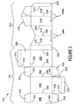
- FIG. 1 there is shown a blank 10 for forming a cushion member or receptacle made from paperboard or other like foldably sheet material.
- the cushion member is adapted to be placed in an outer carton.
- the blank 10 comprises a plurality of side wall panels including a first side wall panel 12, a second side wall panel 14 hingedly connected together along fold line 30.
- the side wall panels 12, 14, 16, 18 are connected together to form a collapsible upright tubular structure for receiving an article
- stabilising means hingedly connected to the panels forming the tubular structure, which stabilising means is adapted for frictional engagement with the inside surface of an outer carton, described below.
- stabilising means is provided by support panels 20, 22 and 24, 26 which are adapted to protrude outwardly beyond one or more corners of the tubular structure.
- support panel 20 is hingedly connected to first side wall panel 12 along fold line 28.
- Support panels 22 and 24 are hingedly connected to second side wall panel 14 and third side wall panel 16 along fold lines 32 and 36 respectively.
- support panels 22 and 24 are hingedly connected together along a common side edge by fold line 34.
- Support panel 26 is hingedly connected to fourth side wall panel 18 along fold line 40.
- article support structure 51 ( Figure 4 ), which comprises a plurality of displaceable strips 49, 49a secured together.
- the first displaceable strip 49 is provided by two outer parts 42, 44 sandwiching central part 46 hingedly connected together in series along fold lines 54 and 56.
- the second displaceable strip 49a is provided by two outer parts 42a, 44a sandwiching central part 46a hingedly connected in series along fold lines 54a, 56a.
- the first displaceable strip 49 is hingedly connected to the first and second side wall panels 12, 14 along fold lines 50 and 52 thereby to bisect fold line 30.
- the second displaceable strip 49a is hingedly connected to the third and fourth side wall panels 16, 18 along fold lines 52a and 50a thereby to bisect fold line 38.
- a top protection structure 59 for supporting an upper portion of an article contained within the cushion member.
- the top protection structure 59 comprises first and second upper panels 60 and 64 that are hingedly connected to third and fourth side wall panels 16 and 18 along fold lines 62 and 66 respectively.
- the fold lines 70 and 72 are arranged such that the gusset panel is, preferably, triangular in shape and is adapted to be folded into face contacting relationship with panels 60 and 64, described below.
- the glue tab 74 is substantially semicircular in shape.
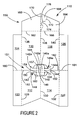
- FIG. 2 A second embodiment of cushion member is illustrated in Figure 2 which shows a blank formed from paperboard or similar foldable sheet material.
- the cushion member is provided with a top protection structure 159, stabilising means and article support structure 151 formed from panels similar to those described in the first embodiment and therefore like parts are designated by the same reference numeral with the prefix'1"and are not therefore described in any greater detail. Only the differences between the first and second embodiments shall be described below.
- first support panel 120, first and second side wall panels 112 and 114 and second support panel 122 are hingedly connected together in series along fold lines 128, 130 and 132 respectively to form one side of the tubular structure.
- support panel 124, third and fourth side wall panels 116,118 and support panel 126 are hingedly connected together in series along fold lines 136, 138 and 140 to form the other side of the cushion member.
- These panels forming each side of the tubular carton are hingedly connected along their respective lower edges.
- the hinged connection is along co-linear fold lines 180 and 181 extending across support panels 120/124, 122/126 only.
- first and second side wall panels 112, 114 are separated from third and fourth side wall panels 116, 118 by cut line 182 which is aligned with and extends between fold lines 180 and 181.
- Cut line 182 extends into the article support structure 151 to separate the opposing outer parts 142, 142a and 144, 144a of the displaceable strips 149, 149a.
- the central displaceable strips 146 and 146a are hingedly connected together along fold line 184. It will be seen from Figure 2 that fold line 184 interrupts cut line 182.
- the platform may further comprise a platform for holding the article.
- the platform is provided by one or more foldable flaps 148 and 148a hingedly connected to the upper edge of the central parts 146, 146a of the displaceable strips.
- the first and second embodiments illustrated in Figures 1 and 2 are adapted to be placed within an outer carton C, an example of which is illustrated in Figure 8 .
- the article support structure 51, 151 and top protection structure 59, 159 could be applied to other types of carton or article carrier, for example wraparound or basket carriers where it is provided to support and/or protect an article.
- FIG. 3 there is shown a blank 210 in which the cushion member 201 and outer carton 301 are formed from a unitary blank of paperboard of similar foldable sheet material.
- the cushion member 201 is similar to the first embodiment and like reference numerals are used to designate common features prefixed with the numeral"2".
- first, second, third and fourth side wall panels 212, 214, 216, 218 hingedly connected together in series along fold lines 230, 234 and 238.
- Article support means formed from displaceable strips 249 and 249a are struck from the first and second side wall panels 212, 214 and third and fourth side wall panels 216, 218 respectively.
- the displaceable strips 249, 249a correspond to the strips 49,49a of the first embodiment.
- top protection structure 259 substantially the same as structure 59 described above.
- the stabilising means is provided at one edge of the tubular structure and is formed by panel 220 hingedly connected to the first side wall panel 212 along fold line 228.
- a glue flap 226 is hingedly connected to the fourth side wall panel 218 along fold line 240 to be glued to the first side wall panel 212.
- the outer carton 301 is constructed from first end panel 286, front panel 288, second end wall panel 290 and rear panel 292 hingedly connected together one to the next along fold lines 294, 296, 298 respectively.
- top and bottom wall panels 306 and securing flaps 310 hingedly connected along fold lines 312 to the top and bottom wall panels which in turn are connected to front and rear panels 288, 292 respectively along fold lines 308.
- the cushion member is hingedly connected to a side edge of one of the panels forming the outer carton.
- the cushion member 201 is hingedly connected to rear panel 292 along fold line 300.
- the cushion member of the first, second and third embodiments is not limited to a rectangular or diamond tubular shape and could comprise other panels to define other polygonal shapes and sizes, depending upon the article to be contained within the cushion member.
- the cushion member and/or article carrier of the present invention can be formed by a series of sequential folding and gluing operations which can be formed in a straight-line machine so that the carton is not required to be rotated or inverted to complete its construction.
- the folding process is not limited to that described below and can be altered according to particular manufacturing requirements.
- side wall panels 12, 14 and support panels 20 and 22 are folded about fold line 34 in direction X ( Figure 1 ) into face contacting relationship with corresponding support panels 24 and 26 and side panels 16 and 18 respectively, as shown in Figure 4 .
- the support panels 22, 24 and 20,26 are secured together by glue or other suitable means known in the art.
- glue is applied to part or all of the section G.
- the central part 46 and 46a of the displaceable strip may be secured together.
- the glue flaps 48, 48a are secured together by glue designated by letter G or other suitable means known in the art.
- Figure 4 shows the carton in a flat collapsed condition ready to be placed in a set up condition to receive the article.
- side panels 12 and 14 are folded out of alignment along fold line 30 and likewise third and fourth side wall panels 16 and 18 are folded out of alignment along fold line 38.
- This folding action causes support panels 20/26 and 22/24 to be folded out of alignment with the adjacent side wall panel along fold lines 28/40 and 32/36.
- an open ended tubular structure is formed, as shown in Figure 5 .
- the structure is diamond shaped although it is envisaged that the carton could be rectangular, trapezoidal, square or another polygonal form.
- the support structure 51 is automatically displaced into the tubular structure whereby the outer parts 42, 42a, 44, 44a of the displaceable strips are folded along fold lines 50, 50a and 52, 52a in an inward direction, shown in Figure 7 , such that the central parts 46, 46a of the displaceable strips remain within a central region of the tubular structure.
- glue flaps 48 and 48a can be folded along their upper edges into a substantially perpendicular relationship with the respective central parts 46, 46a (not shown) of the displaceable strips 49, 49a.
- the glue flaps 48, 48a may be adapted to frictionally engage the base wall of the outer carton, thereby to provide additional stability to the article support structure 51 and in some embodiments is secured thereto by glue or other suitable known means. Thereafter, the article is loaded by relative vertical movement between the article and cushion member. The cushion member and article is loaded into an outer carton C.
- the second embodiment shown in Figure 2 is constructed in a like manner by reference to Figures 2 and 6 whereby support panels 120 and 122 and first and second side panels 112 and 114 are folded about fold line 180, 181 and 184 into face contacting relationship with the respective side wall support panels 124, 126 and third and fourth side wall panels 116 and 118.
- support panels 120, 124 and 122, 126 are secured together by glue or other suitable means known in the art. Construction of the article support structure 151 is substantially the same as for the first embodiment described above and shown in Figure 6 . It is not therefore described in any greater detail.
- the flaps 148, 148a forming the platform structure may be secured together by glue or other suitable means known in the art to provide a double ply platform.
- glue or other suitable means known in the art In order to construct and load the tubular structure of the second embodiment the same folding procedure is carried out as that described above for the first embodiment, so that the platform structure 143 is folded into a substantially horizontal arrangement shown in Figure 6 thereby to provide a platform on which the article rests.
- the flaps 148, 148a may remain unglued and may be folded away from each other to take the respective horizontal positions. In this option, the central parts 146,146a of the displaceable strips 149, 149a may be glued together.
- the support or stabilizing panels 20, 26 and 24, 28 are folded along their common side edges with the tubular structure, such that the support panels are in a substantially parallel arrangement, so that the cushion member can be inserted into the carton, for example a rectangular carton.
- the nature of the paperboard or like material is resilient such that the stabilising panels 22/24 and 20/26 will tend to return to its original orientation with respect to the tubular structure in directions Y and Z ( Figure 7 ) and thus when inserting the carton will frictionally engage the inside surface of the outer carton, shown in Figures 7 and 8 .
- top protecting structure 59 In those cartons with top protecting structure 59, it is constructed by folding upper panels 60 and 64 out of alignment along fold line 70 to allow the tubular structure to be formed as shown in Figure 5 .
- gusset panel 68 In order to close the top protection structure 59, gusset panel 68 is folded along fold lines 70 and 72 to be placed in overlapping face contacting relationship with the upper surface of panel 60 and thereafter the glue tab 74 is secured to the upper surface of panel 60 by glue or other suitable means known in the art.
- the completed top protection structure is shown in Figure 8 and the top 106 and end flaps 102 of the outer carton C are folded over and secured in a closed form as is well known.
- the third embodiment shown in Figure 3 is formed whereby the cushion member 201 is constructed first in a similar manner to the first embodiment described above whereby first and second side wall panels 212 and 214 are placed in face contacting relationship with third and fourth side wall panels 216, 218 and the glue flaps and/or central parts of the displaceable strips 249, 249a of the support structure are glued together as described above.
- the glue flap 226 is folded along the fold line 240 and glued to the inside surface of the first side wall panel 212.
- the panels forming the outer carton are folded about the cushion member in a wraparound fashion whereby panels 290, 292 are folded about fold line 300 into face contacting relationship with side panels 216 and 218 of the cushion member and panels 286 and 288 are folded about fold line 296 to come into face contacting relationship with the opposing side wall panels 212, 214 of the cushion member and is secured together by gluing end panel 286 to support panel 220 thereby to form the carton in a flat collapsed condition.
- the end panels 286,290 and the front and rear panels 288, 292 are separated to form a tubular structure which causes the cushion member side walls 212, 214 and 216, 218 to be separated.
- the support structure 249, 249a is automatically deployed in the manner described above so that an article A can be placed within the cushion member.
- the top protection structure 259 is formed as described above and the base and top panels of the carton can be closed as is well known in the art.
- a carton C substantially similar to that illustrated in Figure 8 .
- the support structure 51; 151; 249, 249a of the invention can be automatically erected so as to act as a strut by employing configurations other than those described above, without departing from the scope of invention.
- the support structure 51 need not be centrally positioned.
- the support structure strengthens the overall carton structure and assists in maintaining a tubular structure when for example the carton is stored on a supermarket shelf.
- the platform 48, 143 provides further support for the article contained within it.
- the support structure can be adapted so that the panels will tend to crumple for example in a vertical plane in the event of excessive or sudden movement of the article within the carton for example during transit, thereby to dissipate the forces, and reduce the risk the article will be damaged.
- hinged connection should not be construed as necessarily referring to a single fold line only: indeed it is envisaged that hinged connection can be formed from one or more of one of the following, a score line, a frangible line or a fold line, without departing from the scope of invention.
- the present invention and it preferred embodiments relate to a carton and/or cushion member which is shaped to provide satisfactory rigidity to hold fragile items such as bottles securely but with a degree of flexibility.
- the shape of the blank minimises the amount of paperboard required for the carton.
- the carton can be constructed from a flat collapsed condition to a position of use by hand or automatic machinery.
- the base configured to act as a. strut can be replaced by a strut formed from other panels of the carton and/or can include one or more struts without departing from the scope of invention.
Landscapes
- Engineering & Computer Science (AREA)
- Mechanical Engineering (AREA)
- Cartons (AREA)
- Packages (AREA)
- Wrapping Of Specific Fragile Articles (AREA)
- Buffer Packaging (AREA)
- Packaging Of Annular Or Rod-Shaped Articles, Wearing Apparel, Cassettes, Or The Like (AREA)
- Mounting, Exchange, And Manufacturing Of Dies (AREA)
- Crushing And Pulverization Processes (AREA)
- Control And Other Processes For Unpacking Of Materials (AREA)
- Refuse Receptacles (AREA)
Abstract
Description
- The present invention relates to a carton and carton blank for forming the cartons. More particularly, the invention relates to a carton and blank for packaging fragile articles such as bottles of perfume for example.
- It is known to provide a two part package comprising an inner cushion member and an outer carton, see for example
US 2 692 077 (KUHLMAN ) orUS 4 114 796 . However, in such cartons, the base, sides and tops of the article can be prone to damage when moved or stored. - The present invention and its preferred embodiments seek to overcome or at least mitigate the problems of the prior art.
- One aspect of the invention provides a receptacle for packaging fragile articles comprising a plurality of side wall panels hinged together to form a collapsible upright tubular structure for receiving an article and an article support structure at the lower end of the tubular structure for supporting the article, wherein the support structure comprises a plurality of displaceable strips secured together such that when the tubular structure is erected from a flap collapsed form, the displaceable strips are automatically displaced into the tubular structure to form a supporting means. Preferably, at least one of the displaceable strips may be provided along its upper edge with a foldable flap for providing a platform for the article.
- According to an optional feature of this aspect of the invention there may comprise two pairs of mutually hinged side wall panels, each pair having a respective displaceable strip wherein the displaceable strips are partially connected. In one embodiment, the displaceable strips may be partially connected along a common lower edge.
- Alternatively, a portion of the displaceable strips may be in face contacting relationship and are secured thereto. Optionally, the support structure may further comprise a pair of glue flaps to secure part of the displaceable strips together.
- A second aspect of the invention provides a cushion member for placement into an outer carton comprising a plurality of side wall panels hinged together to form a collapsible upright tubular structure for receiving an article, and stabilising means hingedly connected to the tubular structure for frictional engagement with the inside surface of the outer carton.
- Preferably, the stabilising means comprises a friction panel extending from the tubular structure to one of the side walls of the outer carton. More preferably, the stabilising means comprises a second friction panel extending from the opposing part of the tubular structure to an opposing side wall of the outer carton.
- A third aspect of the invention provides an article carrier comprising an outer carton and a cushion member, wherein the outer carton has four side walls and the cushion member has a diamond shaped cross section with its four sides disposed intermediate the adjacent side wall of the outer carton wherein the friction panels are hinged respectively to two diametrically opposed corners of the cushion member.
- A fourth aspect of the invention provides an article carrier comprising a plurality of side wall panels hinged together to form a collapsible upright tubular structure for receiving an article and top protection means hinged to the tubular structure wherein the top protection means comprises a first and second top panels hinged respectively to two adjacent side wall panels and wherein there further comprises a gusset panel intermediate and hinged to the first and second top panels. Preferably, there further comprises a glue flap struck from the gusset panel and foldably connected to one of the top panels which glue flap is adapted to be placed in face contacting relationship with the other one of the top panels. A fifth aspect of the invention provides a blank for forming an article carrier for holding fragile articles, which blank comprising a first series of panels and a second series of panels, each series including opposite end panels forming the stabilising means and medial panels for forming a tubular structure wherein the first and second series are hinged together along a common lower edge of the end panels.
- A sixth aspect of the invention provides a blank for forming a receptacle comprising two pairs of mutually hinged side wall panels to form a collapsible upright tubular structure for receiving an article and an article support structure at the lower end of the tubular structure for supporting the article, wherein each pair of side wall panels having a respective displaceable strip for forming a support structure. Optionally, at least one of the displaceable strips is provided along its upper edge with a foldable flap for providing a platform for the article in a set up condition.
- According to an optional feature of the sixth aspect of the invention, the displaceable strips are partially connected along a common lower edge.
- According to an optional feature of the sixth aspect of the invention, the support structure may further comprise a pair of glue flaps to secure part of the displaceable strips together in a set up carton.
- According to a seventh aspect of the invention there is provided a blank for forming a cushion member for placement into an outer carton comprising a plurality of side wall panels hinged together to form a collapsible upright tubular structure for receiving an article, and stabilising means comprising a pair of friction panels extending from the tubular structure to one of the side walls of the outer carton.
- According to an eighth aspect of the invention, there is provided a blank for forming an article carrier comprising a plurality of side panels hinged together to form a collapsible upright tubular structure for receiving an article and top protection means hinged to the tubular structure wherein the top protection structure comprises a first and second top panels hinged respectively to two adjacent side wall panels and wherein there further comprises a gusset panel intermediate and hinged to the top panels. Optionally, there may further comprise a glue flap struck from the gusset panel and foldably connected to one of the top panels which glue flap is adapted to be placed in face contacting relationship with the other one of the top panels.
- Exemplary embodiments of the present invention will now be described, by way of example only, with reference to the accompanying drawings in which:-
-
FIGURE 1 is a plan view of a blank for forming an article cushion member according to the first embodiment of the invention; -
FIGURE 2 is a plan view of a blank for forming an article cushion member of a second embodiment; -
FIGURE 3 is a plan view of a blank for forming an article cushion member and outer carton according to a third embodiment; -
FIGURE 4 is a perspective view of the cushion member of the first embodiment partially formed and in a flat collapsed condition; -
FIGURE 5 is a perspective view of the first embodiment set up and loaded with an article; -
FIGURE 6 is a perspective view from the underside showing the article support means according to one aspect of the invention; -
FIGURE 7 is a bottom plan view of the article support means and outer carton shown inFigure 6 ; and -
FIGURE 8 is a perspective view from above illustrating the top protection structure according to another aspect of the invention. - Referring to the drawings, and in particular
Figure 1 there is shown a blank 10 for forming a cushion member or receptacle made from paperboard or other like foldably sheet material. - The cushion member is adapted to be placed in an outer carton. In this embodiment, the blank 10 comprises a plurality of side wall panels including a first
side wall panel 12, a secondside wall panel 14 hingedly connected together alongfold line 30. There further comprises thirdside wall panel 16 and fourthside wall panel 18 hingedly connected together alongfold line 38. Theside wall panels support panels - Thus it can be seen from
Figure 1 thatsupport panel 20 is hingedly connected to firstside wall panel 12 alongfold line 28.Support panels side wall panel 14 and thirdside wall panel 16 alongfold lines support panels fold line 34.Support panel 26 is hingedly connected to fourthside wall panel 18 alongfold line 40. - Another aspect of the invention is provided by article support structure 51 (
Figure 4 ), which comprises a plurality ofdisplaceable strips Figure 1 , the firstdisplaceable strip 49 is provided by twoouter parts central part 46 hingedly connected together in series alongfold lines displaceable strip 49a is provided by twoouter parts fold lines - Preferably, the first
displaceable strip 49 is hingedly connected to the first and secondside wall panels fold lines fold line 30. The seconddisplaceable strip 49a is hingedly connected to the third and fourthside wall panels fold lines fold line 38. In one class of embodiments, there further comprises aglue flap displaceable strips fold line top protection structure 59 for supporting an upper portion of an article contained within the cushion member. In this embodiment, thetop protection structure 59 comprises first and secondupper panels side wall panels fold lines gusset panel 68 intermediateupper panels fold lines fold lines panels glue tab 74 struck from thegusset panel 68 and connected to one of theupper panels 64, which glue tab extends intogusset panel 68 and is separated therefrom bycut line 76. In this embodiment, theglue tab 74 is substantially semicircular in shape. - A second embodiment of cushion member is illustrated in
Figure 2 which shows a blank formed from paperboard or similar foldable sheet material. In this embodiment, the cushion member is provided with atop protection structure 159, stabilising means andarticle support structure 151 formed from panels similar to those described in the first embodiment and therefore like parts are designated by the same reference numeral with the prefix'1"and are not therefore described in any greater detail. Only the differences between the first and second embodiments shall be described below. - It will be seen that the
first support panel 120, first and secondside wall panels second support panel 122 are hingedly connected together in series alongfold lines support panel 124, third and fourth side wall panels 116,118 andsupport panel 126 are hingedly connected together in series alongfold lines co-linear fold lines support panels 120/124, 122/126 only. Thus first and secondside wall panels side wall panels cut line 182 which is aligned with and extends betweenfold lines Cut line 182 extends into thearticle support structure 151 to separate the opposingouter parts displaceable strips displaceable strips fold line 184. It will be seen fromFigure 2 that foldline 184 interrupts cutline 182. - There may further comprise a platform for holding the article. In this embodiment, the platform is provided by one or more
foldable flaps central parts - The first and second embodiments illustrated in
Figures 1 and2 are adapted to be placed within an outer carton C, an example of which is illustrated inFigure 8 . However, it is envisaged that thearticle support structure top protection structure - Turning to the third embodiment illustrated in
Figure 3 there is shown a blank 210 in which thecushion member 201 andouter carton 301 are formed from a unitary blank of paperboard of similar foldable sheet material. Thecushion member 201 is similar to the first embodiment and like reference numerals are used to designate common features prefixed with the numeral"2". - It will be seen that there comprises first, second, third and fourth
side wall panels fold lines displaceable strips side wall panels side wall panels - The displaceable strips 249, 249a correspond to the
strips - Preferably, there further comprises a
top protection structure 259 substantially the same asstructure 59 described above. - In this embodiment, the stabilising means is provided at one edge of the tubular structure and is formed by
panel 220 hingedly connected to the firstside wall panel 212 alongfold line 228. - A
glue flap 226 is hingedly connected to the fourthside wall panel 218 alongfold line 240 to be glued to the firstside wall panel 212. - The
outer carton 301 is constructed fromfirst end panel 286,front panel 288, secondend wall panel 290 andrear panel 292 hingedly connected together one to the next alongfold lines support flaps 302 hingedly connected to upper and lower edges of theend wall panels - There further comprises top and
bottom wall panels 306 and securingflaps 310 hingedly connected alongfold lines 312 to the top and bottom wall panels which in turn are connected to front andrear panels - The cushion member is hingedly connected to a side edge of one of the panels forming the outer carton. In this embodiment the
cushion member 201 is hingedly connected torear panel 292 alongfold line 300. - The cushion member of the first, second and third embodiments is not limited to a rectangular or diamond tubular shape and could comprise other panels to define other polygonal shapes and sizes, depending upon the article to be contained within the cushion member.
- It is envisaged that the cushion member and/or article carrier of the present invention can be formed by a series of sequential folding and gluing operations which can be formed in a straight-line machine so that the carton is not required to be rotated or inverted to complete its construction. The folding process is not limited to that described below and can be altered according to particular manufacturing requirements.
- Turning to the first embodiment shown in
Figure 1 , in order to set up the cushion member into a position of use,side wall panels support panels fold line 34 in direction X (Figure 1 ) into face contacting relationship withcorresponding support panels side panels Figure 4 . - Optionally, the
support panels - In order to form the
article support structure 51 shown inFigure 7 , thecentral part 46 and 46a of the displaceable strip may be secured together. In those embodiments with glue flaps, the glue flaps 48, 48a are secured together by glue designated by letter G or other suitable means known in the art.Figure 4 shows the carton in a flat collapsed condition ready to be placed in a set up condition to receive the article. - In order to put the
cushion member 10 into a position of use,side panels fold line 30 and likewise third and fourthside wall panels fold line 38. This folding action causessupport panels 20/26 and 22/24 to be folded out of alignment with the adjacent side wall panel alongfold lines 28/40 and 32/36. - By folding the side wall panels in an outward direction, an open ended tubular structure is formed, as shown in
Figure 5 . In this embodiment the structure is diamond shaped although it is envisaged that the carton could be rectangular, trapezoidal, square or another polygonal form. - As the tubular structure is constructed, the
support structure 51 is automatically displaced into the tubular structure whereby theouter parts fold lines Figure 7 , such that thecentral parts 46, 46a of the displaceable strips remain within a central region of the tubular structure. Thereafter, glue flaps 48 and 48a can be folded along their upper edges into a substantially perpendicular relationship with the respectivecentral parts 46, 46a (not shown) of the displaceable strips 49, 49a. In use, the glue flaps 48, 48a may be adapted to frictionally engage the base wall of the outer carton, thereby to provide additional stability to thearticle support structure 51 and in some embodiments is secured thereto by glue or other suitable known means. Thereafter, the article is loaded by relative vertical movement between the article and cushion member. The cushion member and article is loaded into an outer carton C. - The second embodiment shown in
Figure 2 is constructed in a like manner by reference toFigures 2 and6 wherebysupport panels second side panels fold line wall support panels side wall panels support panels article support structure 151 is substantially the same as for the first embodiment described above and shown inFigure 6 . It is not therefore described in any greater detail. - In those embodiments with a
platform structure 143 shown inFigure 6 , theflaps platform structure 143 is folded into a substantially horizontal arrangement shown inFigure 6 thereby to provide a platform on which the article rests. Alternatively, theflaps displaceable strips - In those embodiments with stabilising means, the support or stabilizing
panels panels 22/24 and 20/26 will tend to return to its original orientation with respect to the tubular structure in directions Y and Z (Figure 7 ) and thus when inserting the carton will frictionally engage the inside surface of the outer carton, shown inFigures 7 and 8 . - In those cartons with top protecting
structure 59, it is constructed by foldingupper panels fold line 70 to allow the tubular structure to be formed as shown inFigure 5 . In order to close thetop protection structure 59,gusset panel 68 is folded alongfold lines panel 60 and thereafter theglue tab 74 is secured to the upper surface ofpanel 60 by glue or other suitable means known in the art. The completed top protection structure is shown inFigure 8 and the top 106 and endflaps 102 of the outer carton C are folded over and secured in a closed form as is well known. - The third embodiment shown in
Figure 3 is formed whereby thecushion member 201 is constructed first in a similar manner to the first embodiment described above whereby first and secondside wall panels side wall panels displaceable strips glue flap 226 is folded along thefold line 240 and glued to the inside surface of the firstside wall panel 212. Thereafter, the panels forming the outer carton are folded about the cushion member in a wraparound fashion wherebypanels fold line 300 into face contacting relationship withside panels panels fold line 296 to come into face contacting relationship with the opposingside wall panels end panel 286 to supportpanel 220 thereby to form the carton in a flat collapsed condition. - In order to construct the tubular structure and carton C, the end panels 286,290 and the front and
rear panels member side walls support structure top protection structure 259 is formed as described above and the base and top panels of the carton can be closed as is well known in the art. Thus there is provided a carton C substantially similar to that illustrated inFigure 8 . - It is envisaged that the
support structure 51; 151; 249, 249a of the invention can be automatically erected so as to act as a strut by employing configurations other than those described above, without departing from the scope of invention. For example, thesupport structure 51 need not be centrally positioned. The support structure strengthens the overall carton structure and assists in maintaining a tubular structure when for example the carton is stored on a supermarket shelf. Theplatform - Furthermore the support structure can be adapted so that the panels will tend to crumple for example in a vertical plane in the event of excessive or sudden movement of the article within the carton for example during transit, thereby to dissipate the forces, and reduce the risk the article will be damaged.
- It will be recognised that as used herein, directional references such as "top", "base", "end", "side", "upper" and "lower" do not limit the respective panels to such orientation, but merely serve to distinguish these panels from one another. Any reference to hinged connection should not be construed as necessarily referring to a single fold line only: indeed it is envisaged that hinged connection can be formed from one or more of one of the following, a score line, a frangible line or a fold line, without departing from the scope of invention.
- The present invention and it preferred embodiments relate to a carton and/or cushion member which is shaped to provide satisfactory rigidity to hold fragile items such as bottles securely but with a degree of flexibility. The shape of the blank minimises the amount of paperboard required for the carton. The carton can be constructed from a flat collapsed condition to a position of use by hand or automatic machinery. Furthermore, the base configured to act as a. strut can be replaced by a strut formed from other panels of the carton and/or can include one or more struts without departing from the scope of invention.
Claims (10)
- A cushion member for placement into an outer carton comprising a plurality of side wall panels hinged together to form a collapsible upright tubular structure for receiving an article, and stabilising means hingedly connected to the tubular structure for frictional engagement with the inside surface of the outer carton.
- The cushion member as claimed in claim 1 wherein the stabilising means comprises a friction panel extending from the tubular structure to one of the side walls of the outer carton.
- The cushion member as claimed in claim 2 wherein the stabilising means comprises a second friction panel extending from the opposing part of the tubular structure to an opposing side wall of the outer carton.
- A blank for forming a cushion member for placement into an outer carton comprising a plurality of side wall panels hinged together to form a collapsible upright tubular structure for receiving an article, and stabilising means comprising a pair of friction panels extending from the tubular structure to one of the side walls of the outer carton.
- An article carrier comprising an outer carton and a cushion member as claimed in claims 1 to 3, wherein the outer carton has four side walls and the cushion member has a diamond shaped cross section with its four sides disposed intermediate the adjacent side wall of the outer carton wherein the friction panels are hinged respectively to two diametrically opposed corners of the cushion member.
- An article carrier comprising a plurality of side wall panels hinged together to form a collapsible upright tubular structure for receiving an article and top protection means hinged to the tubular structure wherein the top protection means comprises a first and second top panels hinged respectively to two adjacent side wall panels and wherein there further comprises a gusset panel intermediate and hinged to the first and second top panels.
- The article carrier as claimed in claim 6 wherein there further comprises a glue tab struck from the gusset panel and connected to one of the top panels which glue tab is adapted to be placed in face contacting relationship with the other one of the top panels.
- A blank for forming an article carrier comprising a plurality of side panels hinged together to form a collapsible upright tubular structure for receiving an article and a top protection structure hinged to the tubular structure wherein the top protection structure comprises a first and second top panels hinged respectively to two adjacent side wall panels and wherein there further comprises a gusset panel intermediate and hinged to the first and second top panels.
- The blank for forming an article carrier as claimed in claim 8 wherein there further comprises a glue tab struck from the gusset panel and connected to one of the top panels which glue tab is adapted to be placed in face contacting relationship with the other one of the top panels
- A blank for forming an article carrier for holding fragile articles, which blank comprises a first series of panels and a second series of panels, each series including opposite end panels forming the stabilising means and medial panels for forming a tubular structure wherein the first and second series are hinged together along a common lower edge of the end panels.
Applications Claiming Priority (2)
| Application Number | Priority Date | Filing Date | Title |
|---|---|---|---|
| GBGB0002991.8A GB0002991D0 (en) | 2000-02-10 | 2000-02-10 | Carton and carton blank |
| EP01910550A EP1409356B1 (en) | 2000-02-10 | 2001-02-09 | Article carrier for fragile articles and corresponding blank |
Related Parent Applications (2)
| Application Number | Title | Priority Date | Filing Date |
|---|---|---|---|
| EP01910550A Division EP1409356B1 (en) | 2000-02-10 | 2001-02-09 | Article carrier for fragile articles and corresponding blank |
| EP01910550.1 Division | 2001-02-09 |
Publications (2)
| Publication Number | Publication Date |
|---|---|
| EP1985545A2 true EP1985545A2 (en) | 2008-10-29 |
| EP1985545A3 EP1985545A3 (en) | 2010-09-22 |
Family
ID=9885260
Family Applications (2)
| Application Number | Title | Priority Date | Filing Date |
|---|---|---|---|
| EP08160606A Withdrawn EP1985545A3 (en) | 2000-02-10 | 2001-02-09 | Article carrier for fragile articles and corresponding blank |
| EP01910550A Expired - Lifetime EP1409356B1 (en) | 2000-02-10 | 2001-02-09 | Article carrier for fragile articles and corresponding blank |
Family Applications After (1)
| Application Number | Title | Priority Date | Filing Date |
|---|---|---|---|
| EP01910550A Expired - Lifetime EP1409356B1 (en) | 2000-02-10 | 2001-02-09 | Article carrier for fragile articles and corresponding blank |
Country Status (7)
| Country | Link |
|---|---|
| EP (2) | EP1985545A3 (en) |
| AT (1) | ATE404442T1 (en) |
| AU (1) | AU2001238145A1 (en) |
| CA (1) | CA2399622C (en) |
| DE (1) | DE60135389D1 (en) |
| GB (1) | GB0002991D0 (en) |
| WO (1) | WO2001058768A2 (en) |
Cited By (1)
| Publication number | Priority date | Publication date | Assignee | Title |
|---|---|---|---|---|
| US11673708B2 (en) | 2020-05-11 | 2023-06-13 | Packaging Corporation Of America | Single-piece package to contain and protect product |
Families Citing this family (1)
| Publication number | Priority date | Publication date | Assignee | Title |
|---|---|---|---|---|
| CN207943275U (en) | 2017-10-10 | 2018-10-09 | 苏州伍洲设计包装有限公司 | A kind of packing box |
Citations (2)
| Publication number | Priority date | Publication date | Assignee | Title |
|---|---|---|---|---|
| US2692077A (en) | 1948-12-11 | 1954-10-19 | Rca Corp | Package for radio tubes and the like |
| US4114796A (en) | 1976-10-26 | 1978-09-19 | Consolidated Packaging, Inc. | Container having braced partitions |
Family Cites Families (7)
| Publication number | Priority date | Publication date | Assignee | Title |
|---|---|---|---|---|
| GB367069A (en) * | 1930-12-02 | 1932-02-18 | Edison Swan Electric Co Ltd | Improvements relating to the packing of fragile articles |
| US2643814A (en) * | 1948-11-06 | 1953-06-30 | Waddington Ltd J | Carton for round-ended articles |
| FR1097410A (en) * | 1954-03-26 | 1955-07-05 | Ferembal Sa | Packaging and presentation box |
| US3075683A (en) * | 1961-11-07 | 1963-01-29 | Donrico Inc | Shockproof or cushioned carton |
| US3217960A (en) * | 1963-06-13 | 1965-11-16 | Downingtown Paper Company | Protective shock-resistant carton |
| FR2170930B1 (en) * | 1972-02-03 | 1974-05-10 | Alpes Cartonnerie Modern | |
| US4335842A (en) * | 1980-12-12 | 1982-06-22 | W. J. Bradford Paper Company | Three compartment divider |
-
2000
- 2000-02-10 GB GBGB0002991.8A patent/GB0002991D0/en not_active Ceased
-
2001
- 2001-02-09 WO PCT/US2001/004427 patent/WO2001058768A2/en not_active Ceased
- 2001-02-09 EP EP08160606A patent/EP1985545A3/en not_active Withdrawn
- 2001-02-09 DE DE60135389T patent/DE60135389D1/en not_active Expired - Fee Related
- 2001-02-09 CA CA002399622A patent/CA2399622C/en not_active Expired - Fee Related
- 2001-02-09 EP EP01910550A patent/EP1409356B1/en not_active Expired - Lifetime
- 2001-02-09 AT AT01910550T patent/ATE404442T1/en not_active IP Right Cessation
- 2001-02-09 AU AU2001238145A patent/AU2001238145A1/en not_active Abandoned
Patent Citations (2)
| Publication number | Priority date | Publication date | Assignee | Title |
|---|---|---|---|---|
| US2692077A (en) | 1948-12-11 | 1954-10-19 | Rca Corp | Package for radio tubes and the like |
| US4114796A (en) | 1976-10-26 | 1978-09-19 | Consolidated Packaging, Inc. | Container having braced partitions |
Cited By (1)
| Publication number | Priority date | Publication date | Assignee | Title |
|---|---|---|---|---|
| US11673708B2 (en) | 2020-05-11 | 2023-06-13 | Packaging Corporation Of America | Single-piece package to contain and protect product |
Also Published As
| Publication number | Publication date |
|---|---|
| EP1409356A2 (en) | 2004-04-21 |
| EP1409356B1 (en) | 2008-08-13 |
| WO2001058768A3 (en) | 2003-05-01 |
| AU2001238145A1 (en) | 2001-08-20 |
| GB0002991D0 (en) | 2000-03-29 |
| WO2001058768A2 (en) | 2001-08-16 |
| CA2399622C (en) | 2007-10-16 |
| ATE404442T1 (en) | 2008-08-15 |
| CA2399622A1 (en) | 2001-08-16 |
| DE60135389D1 (en) | 2008-09-25 |
| EP1985545A3 (en) | 2010-09-22 |
Similar Documents
| Publication | Publication Date | Title |
|---|---|---|
| US6474473B2 (en) | Shipping and display container for bottles | |
| US7073705B2 (en) | Carton with a glued insert and a blank combination for forming the same | |
| US7063208B2 (en) | Article carrier and blank therefor | |
| US6189687B1 (en) | Article carrier and blank therefor | |
| US6666333B2 (en) | Carton and carton blank | |
| US6789678B2 (en) | Carton for fragile article | |
| US20030034273A1 (en) | Carton and a cushion member for placement into a carton | |
| WO2002030764A2 (en) | Carton and carton blanks | |
| US6505739B2 (en) | Carton and carton blank | |
| US6568585B2 (en) | Carton and carton blank | |
| US20050224390A1 (en) | Carton insert and packaged carton | |
| US4264006A (en) | Shadow box with improved platform assembly | |
| EP1409356B1 (en) | Article carrier for fragile articles and corresponding blank | |
| EP1125850B1 (en) | Carton and carton blank | |
| US6945390B2 (en) | Article carrier with handle-reinforcing bridging structure | |
| CA2417599C (en) | Carton and carton blank | |
| CA2391215C (en) | Carton and carton blanks | |
| WO2003053796A1 (en) | Carton and carton blank | |
| US6866144B2 (en) | Carton and carton blank | |
| EP1124740B1 (en) | Carton and carton blank | |
| CA2067995C (en) | Display carrier with dividing member | |
| EP1141377B1 (en) | Carton and carton blank | |
| EP1528005A1 (en) | Carton and carton blanks | |
| EP1259433B1 (en) | Carton and carton blank | |
| WO2004063027A2 (en) | Tray container and blank |
Legal Events
| Date | Code | Title | Description |
|---|---|---|---|
| PUAI | Public reference made under article 153(3) epc to a published international application that has entered the european phase |
Free format text: ORIGINAL CODE: 0009012 |
|
| 17P | Request for examination filed |
Effective date: 20080717 |
|
| AC | Divisional application: reference to earlier application |
Ref document number: 1409356 Country of ref document: EP Kind code of ref document: P |
|
| AK | Designated contracting states |
Kind code of ref document: A2 Designated state(s): AT BE CH CY DE DK ES FI FR GB GR IE IT LI LU MC NL PT SE TR |
|
| RAP1 | Party data changed (applicant data changed or rights of an application transferred) |
Owner name: MEADWESTVACO PACKAGING SYSTEMS LLC |
|
| PUAL | Search report despatched |
Free format text: ORIGINAL CODE: 0009013 |
|
| AK | Designated contracting states |
Kind code of ref document: A3 Designated state(s): AT BE CH CY DE DK ES FI FR GB GR IE IT LI LU MC NL PT SE TR |
|
| STAA | Information on the status of an ep patent application or granted ep patent |
Free format text: STATUS: THE APPLICATION IS DEEMED TO BE WITHDRAWN |
|
| 18D | Application deemed to be withdrawn |
Effective date: 20100901 |