EP1985368A1 - Microtube picking device for pharmaceutical development - Google Patents
Microtube picking device for pharmaceutical development Download PDFInfo
- Publication number
- EP1985368A1 EP1985368A1 EP08004801A EP08004801A EP1985368A1 EP 1985368 A1 EP1985368 A1 EP 1985368A1 EP 08004801 A EP08004801 A EP 08004801A EP 08004801 A EP08004801 A EP 08004801A EP 1985368 A1 EP1985368 A1 EP 1985368A1
- Authority
- EP
- European Patent Office
- Prior art keywords
- microtube
- picking
- picking device
- accommodating hole
- pharmaceutical development
- Prior art date
- Legal status (The legal status is an assumption and is not a legal conclusion. Google has not performed a legal analysis and makes no representation as to the accuracy of the status listed.)
- Granted
Links
Images



Classifications
-
- G—PHYSICS
- G01—MEASURING; TESTING
- G01N—INVESTIGATING OR ANALYSING MATERIALS BY DETERMINING THEIR CHEMICAL OR PHYSICAL PROPERTIES
- G01N35/00—Automatic analysis not limited to methods or materials provided for in any single one of groups G01N1/00 - G01N33/00; Handling materials therefor
- G01N35/02—Automatic analysis not limited to methods or materials provided for in any single one of groups G01N1/00 - G01N33/00; Handling materials therefor using a plurality of sample containers moved by a conveyor system past one or more treatment or analysis stations
- G01N35/04—Details of the conveyor system
-
- B—PERFORMING OPERATIONS; TRANSPORTING
- B01—PHYSICAL OR CHEMICAL PROCESSES OR APPARATUS IN GENERAL
- B01L—CHEMICAL OR PHYSICAL LABORATORY APPARATUS FOR GENERAL USE
- B01L9/00—Supporting devices; Holding devices
- B01L9/50—Clamping means, e.g. tongs
-
- G—PHYSICS
- G01—MEASURING; TESTING
- G01N—INVESTIGATING OR ANALYSING MATERIALS BY DETERMINING THEIR CHEMICAL OR PHYSICAL PROPERTIES
- G01N35/00—Automatic analysis not limited to methods or materials provided for in any single one of groups G01N1/00 - G01N33/00; Handling materials therefor
- G01N35/02—Automatic analysis not limited to methods or materials provided for in any single one of groups G01N1/00 - G01N33/00; Handling materials therefor using a plurality of sample containers moved by a conveyor system past one or more treatment or analysis stations
- G01N35/04—Details of the conveyor system
- G01N2035/0401—Sample carriers, cuvettes or reaction vessels
- G01N2035/0406—Individual bottles or tubes
- G01N2035/041—Individual bottles or tubes lifting items out of a rack for access
-
- G—PHYSICS
- G01—MEASURING; TESTING
- G01N—INVESTIGATING OR ANALYSING MATERIALS BY DETERMINING THEIR CHEMICAL OR PHYSICAL PROPERTIES
- G01N35/00—Automatic analysis not limited to methods or materials provided for in any single one of groups G01N1/00 - G01N33/00; Handling materials therefor
- G01N35/0099—Automatic analysis not limited to methods or materials provided for in any single one of groups G01N1/00 - G01N33/00; Handling materials therefor comprising robots or similar manipulators
Definitions
- the present invention relates to a microtube picking device for pharmaceutical development suitable for taking out or taking in a selected microtube accommodated in a storage rack in high density in a field of pharmaceutical development, study and the like.
- a storage and a transfer have been carried out by sealing a sample-solved solution into a vessel called a microtube having an upper part and a lower part.
- the upper part is larger in outline than the lower part.
- a plurality of the microtubes stand vertically in a storage rack, defined as a grid shape, for example a storage rack defined into 96 in 8 rows and 12 columns (hereinafter referred to as "96 tube racks") to accommodate them.
- a storage rack having a total defined number of 384 microtube in 16 rows and 24 columns hereinafter referred to as "384 tube racks" has been also known to accommodate smaller microtube.
- a microtube picking device 500 for pharmaceutical development As a microtube picking device for pharmaceutical development for taking a selected microtube out of or into such a 96 tube racks or 384 tube racks, a microtube picking device 500 for pharmaceutical development as shown in FIG. 9 has been known.
- This microtube picking device 500 for pharmaceutical development has insertion holes 532, into which the microtube are loosely supported.
- the insertion holes have a cross section smaller than the upper parts and larger than the lower parts of the microtube which fit to a lower part of the microtube 510 to support the microtube, and are formed in a storage rack 530.
- the picking device 500 has a plunger member 540 which may be protruded to displace a selected microtube 510 directly above through the insertion hole 532 of the storage rack 530 by abutting the bottom surface of the microtube 510.
- the plunger member is at a lower position than the storage rack 530, and a concurrently-lifting prevention member 560 is positioned above the top surfaces of the surrounding microtube so that the microtube pushed up with the plunger member 540 does not lift the surrounding microtube together exists at upper position than microtube 510,
- the microtube picking device 500 has opposed gripping members 522, which provide a space slightly smaller in size than the size of the upper part of the protruded up microtube 510 and sandwich the microtube between the opposed gripping members to grip the microtube 510 which was advanced in accordance with a protrusion-up operation by the plunger member 540 under the microtube 510 by allowing the space between the resilient gripping members 522 to be narrowed to accommodate the microtube,
- the gripping members 522 are provided on both sides of the microtube 510 and are deflected, unbalance occurs in the respective amounts of deflections of the members 522 and the microtube becomes off-center and the position of the microtube 510 is not kept properly centered. Thus, since the position of the microtube 510 is shifted, the microtube 510 cannot be re-inserted into the storage rack 530.
- the microtube since the sandwich directions of the gripping members 522 are directed to opposed two surfaces, the microtube sometimes is inclined to a direction perpendicular to the surfaces. As a result a phenomenon that the microtube 510 cannot be re-inserted into the storage rack 530 occurs.
- one object of the present invention is to provide a microtube picking device for pharmaceutical development in which the picking of a microtube can be reliably carried out without producing friction in a gripping member and without shifting the centered position of the microtube.
- a microtube picking device for pharmaceutical development having a picking member, which clamps a microtube, which seals a sample for pharmaceutical development, when a selected one microtube is taken out of a storage rack, which vertically accommodates a plurality of microtube in a matrix manner and accommodates a microtube at a predetermined accommodation position in said storage rack, characterized in that said picking member has a microtube accommodating hole whose internal surfaces are disposed in a polygonal array and has at least one latch member having elastic force, which presses and fixes said microtube to two adjacent opposite surfaces of the microtube accommodating hole.
- One of the embodiments of the invention further solves the above-mentioned problems by attaching a latch member to each of two adjacent surfaces of the microtube accommodating hole, one for each of the two opposite surfaces.
- metal used in the latch member has sufficient elastic force
- the metal is not limited. However, as such metals are expensive, an easily workable steel is preferably used.
- a microtube picking device for pharmaceutical development having a picking member, which clamps a microtube which seals a sample for pharmaceutical development, when a selected one microtube is taken out of a storage rack, which vertically accommodates a plurality of microtubes in a matrix manner and accommodates a microtube at a predetermined accommodation position in said storage rack
- said picking member has a microtube accommodating hole whose internal surface is a polygon and has at least one latch member having elastic force, which presses and fixes said microtube to adjacent two surfaces of the microtube accommodating hole, the microtube is positioned by being abutted on the adjacent two surfaces, which are reference surfaces of the microtube accommodating hole.
- the microtube does not incline and is clamped at the same position in the microtube accommodating hole. Further, since the clamping position and the clamping stance of the microtube are constant, the microtube can be reinserted into a storage rack.
- the same magnitude force is applied by the two latch members, and due to the relationship between action and reaction, a uniform force is applied to the clamped microtube from the all directions.
- a uniform force is applied to the clamped microtube from the all directions.
- the latch member When the latch member is formed of metal, if the latch member collides with a tab of an aluminum foil covering the opening portion of the microtube, it does not produce friction. Thus the endurance of the latch member is improved.
- FIG. 1 is a perspective view of a picking member of a microtube picking device for pharmaceutical development according to example 1.
- FIG. 2 is a perspective view of the picking member shown in FIG. 1 viewed from a direction of an arrow II.
- FIG. 3 is a front view of the picking member shown in FIG. 1 viewed from a direction of an arrow III.
- FIG. 4 is a side view of the picking member shown in FIG. 3 viewed from a direction of an arrow IV.
- FIG. 5 is a top view of the picking member shown in FIG. 3 viewed from a direction of an arrow V.
- FIG. 6 is a bottom view of the picking member shown in FIG. 3 viewed from a direction of an arrow VI.
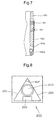
- FIG. 7 is a fragmentary cross section taken on the line VII-VII of FIG. 5 .
- FIG. 8 is a top view of a picking member of a microtube picking device for pharmaceutical development according to example 2.
- FIG. 9 is a diagrammatic view explaining a prior art microtube picking device.
- the present invention comprises a microtube picking device for pharmaceutical development having a picking member, which grips a microtube containing a sample for pharmaceutical development, so that a selected one microtube may be taken out of a storage rack, which vertically accommodates a plurality of microtubes in a matrix manner and accommodates the selected microtube at a predetermined accommodation position in said storage rack.
- the picking member has a microtube-accommodating hole whose internal surface is a polygon and has at least one latch member having elastic force, which presses and fixes said microtube to adjacent two surfaces of the microtube accommodating hole.
- the present invention provides a microtube picking device for pharmaceutical development in which a latch member does not shift the insertion position of the selected microtube in the storage rack and picking and reinsertion of the microtube can be reliably performed.
- a latch member does not shift the insertion position of the selected microtube in the storage rack and picking and reinsertion of the microtube can be reliably performed.
- Any concrete form of the picking device or other configurations and the like may be used.
- FIGS. 1-7 illustrate a first example of a picking member 100 used in a microtube picking device for pharmaceutical development according to the present invention.
- the member comprises a pair of side members 110 and 120 having an L-shaped cross-section fixed together to provide a microtube accommodating hole 150 whose combined internal portion is a box space of a square cross section.
- the side member 120 is a latch supporting member, which supports two latch members 130 and 140 formed as plate springs of steel iron.
- the latch member 140 has a free and circularly bent end 130a as shown in FIG 7 and by a hidden line in FIG. 4 .
- the latch member 140 has the same shape as the latch member 130 as shown by a hidden line in FIG. 3 .
- the end circular portions 130a and 140a of these latch members 130 and 140 are respectively protruded past the interior surface into the microtube accommodating hole 150 through insertion orifices 120a and 120b provided below a portion where the latch members 130 and 140 of the latch supporting member 120 are adhered, for example by fasteners 131 and 141.
- the latch slides over the upper part, past the junction between the upper part and the lower part and engages against the lower part, and when the microtube is pushed downwardly out of the microtube accommodating hole 150 for reinsertion into a rack, the above-mentioned configuration of the latch members 130 and 140 can smoothly slide over the junction and the upper part of the microtube.
- a horizontal cross-sectional shape of the microtube is a square of 4.3 mm. per side
- the free end circular portions 130a and 140a are respectively retracted backward by 0.4 mm and the microtube is pressed against two reference surfaces 110a and 110b forming a microtube accommodating hole 150 of the reference latch member 110, which crosses at a right angle, so that the microtube can be held at a correct position without being inclined or fallen down.
- the wall members 120 At the bottom of the microtube accommodating hole 150 as shown in FIG. 6 , the wall members 120 have tapered portions 120c and 130b to facilitate the operation when the microtube is taken in or taken out of the microtube accommodating hole 150. Therefore the coming in and going out of the microtube becomes smooth.
- the picking members are basically the same as the illustrated microtube picking device for pharmaceutical development, The description of the different configurations of other parts are omitted.
- a resilient metallic plate spring is utilized in example 1, if there is room for it, a coil spring may be combined with a plate to produce the pressing of the microtube against the two opposite surfaces of the microtube accommodating hole.
- Example 2 which is another embodiment according to the present invention, will be described with reference to FIG. 8 .
- FIG. 8 is a top view of a picking member 200 in example 2.
- This picking member 200 has a target of a cylindrical microtube 250.
- the micro-tube-receiving hole of the member 200 is formed by surfaces arrayed in a triangular orientation, and uses two surfaces at 60 degrees as reference surfaces 210 and 220.
- the microtube 250 is clamped by pressing the microtube 250 against the reference surfaces 210 and 220 in a direction by a spring member 230, which is mounted on the third wall opposite the corner between the two reference surfaces, and enters the hole through an orifice in the third wall. In this case the microtube can be held at a correct position without being inclined.
- the latch member 230 slides over the upper part, past the junction between the upper part and the lower part and engages against the lower part, and when the microtube is pushed downwardly out of the microtube accommodating hole for reinsertion into a rack, the latch member 230 can smoothly slide over the junction and the upper part of the microtube as in example 1.
- microtube picking device for pharmaceutical development of the present invention reliable taking out and accommodation operation of a microtube accommodated in a tube rack 384, which have been difficult, is not only realized but also the technical idea can be applied to a tube-shaped vessel other than the microtube.
- the industrial applicability is very high.
Landscapes
- Physics & Mathematics (AREA)
- Health & Medical Sciences (AREA)
- Life Sciences & Earth Sciences (AREA)
- Chemical & Material Sciences (AREA)
- Analytical Chemistry (AREA)
- Biochemistry (AREA)
- General Health & Medical Sciences (AREA)
- General Physics & Mathematics (AREA)
- Immunology (AREA)
- Pathology (AREA)
- Automatic Analysis And Handling Materials Therefor (AREA)
Abstract
Description
- The present invention relates to a microtube picking device for pharmaceutical development suitable for taking out or taking in a selected microtube accommodated in a storage rack in high density in a field of pharmaceutical development, study and the like.
- In a field of pharmaceutical development, study and the like, a storage and a transfer have been carried out by sealing a sample-solved solution into a vessel called a microtube having an upper part and a lower part. The upper part is larger in outline than the lower part. A plurality of the microtubes stand vertically in a storage rack, defined as a grid shape, for example a storage rack defined into 96 in 8 rows and 12 columns (hereinafter referred to as "96 tube racks") to accommodate them. Further, a storage rack having a total defined number of 384 microtube in 16 rows and 24 columns (hereinafter referred to as "384 tube racks") has been also known to accommodate smaller microtube.
- As a microtube picking device for pharmaceutical development for taking a selected microtube out of or into such a 96 tube racks or 384 tube racks, a
microtube picking device 500 for pharmaceutical development as shown inFIG. 9 has been known. Thismicrotube picking device 500 for pharmaceutical development hasinsertion holes 532, into which the microtube are loosely supported. The insertion holes have a cross section smaller than the upper parts and larger than the lower parts of the microtube which fit to a lower part of themicrotube 510 to support the microtube, and are formed in astorage rack 530. Thepicking device 500 has aplunger member 540 which may be protruded to displace aselected microtube 510 directly above through theinsertion hole 532 of thestorage rack 530 by abutting the bottom surface of themicrotube 510. The plunger member is at a lower position than thestorage rack 530, and a concurrently-lifting prevention member 560 is positioned above the top surfaces of the surrounding microtube so that the microtube pushed up with theplunger member 540 does not lift the surrounding microtube together exists at upper position thanmicrotube 510, Themicrotube picking device 500 has opposedgripping members 522, which provide a space slightly smaller in size than the size of the upper part of the protruded upmicrotube 510 and sandwich the microtube between the opposed gripping members to grip themicrotube 510 which was advanced in accordance with a protrusion-up operation by theplunger member 540 under themicrotube 510 by allowing the space between theresilient gripping members 522 to be narrowed to accommodate the microtube, Themicrotube picking device 500 also has a dispensingplunger member 550, which discharges themicrotube 510 gripped by the pickingmember 520. The material of aresilient gripping members 522 is preferably a plastic such as polypropylene having sufficient elastic force at a very low temperature to grip the microtube. (SeeFig. 1 of Japanese Laid-Open Patent Publication No.2006-214919 - It is generally the practice, when using the 384 tube racks, to form a closure on the microtube by fusion-welding an aluminum foil to an opening portion of the top of the microtube. A small tab portion of the aluminum foil is extended beyond a wall of the opening of the microtube. Thus there is a problem that the tab portion causes friction to occur with the
resilient gripping member 522. - Further, since the gripping
members 522 are provided on both sides of themicrotube 510 and are deflected, unbalance occurs in the respective amounts of deflections of themembers 522 and the microtube becomes off-center and the position of themicrotube 510 is not kept properly centered. Thus, since the position of themicrotube 510 is shifted, themicrotube 510 cannot be re-inserted into thestorage rack 530. - Further, since the sandwich directions of the gripping
members 522 are directed to opposed two surfaces, the microtube sometimes is inclined to a direction perpendicular to the surfaces. As a result a phenomenon that themicrotube 510 cannot be re-inserted into thestorage rack 530 occurs. - Accordingly, one object of the present invention is to provide a microtube picking device for pharmaceutical development in which the picking of a microtube can be reliably carried out without producing friction in a gripping member and without shifting the centered position of the microtube.
- The object is solved by the features of claim 1. Further advantageous features are the subject-matter of the dependent claims. According to one aspect of the invention, a microtube picking device for pharmaceutical development is provided having a picking member, which clamps a microtube, which seals a sample for pharmaceutical development, when a selected one microtube is taken out of a storage rack, which vertically accommodates a plurality of microtube in a matrix manner and accommodates a microtube at a predetermined accommodation position in said storage rack, characterized in that said picking member has a microtube accommodating hole whose internal surfaces are disposed in a polygonal array and has at least one latch member having elastic force, which presses and fixes said microtube to two adjacent opposite surfaces of the microtube accommodating hole.
- One of the embodiments of the invention further solves the above-mentioned problems by attaching a latch member to each of two adjacent surfaces of the microtube accommodating hole, one for each of the two opposite surfaces.
- According to a further aspect the above-mentioned problems are solved by forming the latch member of metal.
- If metal used in the latch member has sufficient elastic force, the metal is not limited. However, as such metals are expensive, an easily workable steel is preferably used.
- In a microtube picking device for pharmaceutical development having a picking member, which clamps a microtube which seals a sample for pharmaceutical development, when a selected one microtube is taken out of a storage rack, which vertically accommodates a plurality of microtubes in a matrix manner and accommodates a microtube at a predetermined accommodation position in said storage rack, said picking member has a microtube accommodating hole whose internal surface is a polygon and has at least one latch member having elastic force, which presses and fixes said microtube to adjacent two surfaces of the microtube accommodating hole, the microtube is positioned by being abutted on the adjacent two surfaces, which are reference surfaces of the microtube accommodating hole. Thus the microtube does not incline and is clamped at the same position in the microtube accommodating hole. Further, since the clamping position and the clamping stance of the microtube are constant, the microtube can be reinserted into a storage rack.
- In the embodiment in which two latch members face the adjacent reference surfaces of the microtube accommodating hole respectively, the same magnitude force is applied by the two latch members, and due to the relationship between action and reaction, a uniform force is applied to the clamped microtube from the all directions. Thus the microtube can be stabilized when being inserted into the storage rack.
- When the latch member is formed of metal, if the latch member collides with a tab of an aluminum foil covering the opening portion of the microtube, it does not produce friction. Thus the endurance of the latch member is improved.
-
FIG. 1 is a perspective view of a picking member of a microtube picking device for pharmaceutical development according to example 1. -
FIG. 2 is a perspective view of the picking member shown inFIG. 1 viewed from a direction of an arrow II. -
FIG. 3 is a front view of the picking member shown inFIG. 1 viewed from a direction of an arrow III. -
FIG. 4 is a side view of the picking member shown inFIG. 3 viewed from a direction of an arrow IV. -
FIG. 5 is a top view of the picking member shown inFIG. 3 viewed from a direction of an arrow V. -
FIG. 6 is a bottom view of the picking member shown inFIG. 3 viewed from a direction of an arrow VI. -
FIG. 7 is a fragmentary cross section taken on the line VII-VII ofFIG. 5 . -
FIG. 8 is a top view of a picking member of a microtube picking device for pharmaceutical development according to example 2. -
FIG. 9 is a diagrammatic view explaining a prior art microtube picking device. - The present invention comprises a microtube picking device for pharmaceutical development having a picking member, which grips a microtube containing a sample for pharmaceutical development, so that a selected one microtube may be taken out of a storage rack, which vertically accommodates a plurality of microtubes in a matrix manner and accommodates the selected microtube at a predetermined accommodation position in said storage rack. The picking member has a microtube-accommodating hole whose internal surface is a polygon and has at least one latch member having elastic force, which presses and fixes said microtube to adjacent two surfaces of the microtube accommodating hole. The present invention provides a microtube picking device for pharmaceutical development in which a latch member does not shift the insertion position of the selected microtube in the storage rack and picking and reinsertion of the microtube can be reliably performed. Any concrete form of the picking device or other configurations and the like may be used.
-
FIGS. 1-7 illustrate a first example of a pickingmember 100 used in a microtube picking device for pharmaceutical development according to the present invention. The member comprises a pair ofside members hole 150 whose combined internal portion is a box space of a square cross section. Theside member 120 is a latch supporting member, which supports twolatch members - The
latch member 140 has a free and circularlybent end 130a as shown inFIG 7 and by a hidden line inFIG. 4 . Thelatch member 140 has the same shape as thelatch member 130 as shown by a hidden line inFIG. 3 . The endcircular portions latch members microtube accommodating hole 150 throughinsertion orifices latch members latch supporting member 120 are adhered, for example byfasteners microtube accommodating hole 150, the latch slides over the upper part, past the junction between the upper part and the lower part and engages against the lower part, and when the microtube is pushed downwardly out of themicrotube accommodating hole 150 for reinsertion into a rack, the above-mentioned configuration of thelatch members - Since in example 1, a horizontal cross-sectional shape of the microtube is a square of 4.3 mm. per side, the shape of an internal surface of the
microtube accommodating hole 150 is set to a square of L1 = L2 = 4.4 mm. per side, as shown inFIG. 6 . As shown inFIG. 5 , the top endcircular portions latch members microtube accommodating hole 150 by D = 0.5 mm. That is when a microtube is advanced into themicrotube accommodating hole 150 through an internal portion at a lower end of a pickingmember 100 in accordance with a protrusion-up operation by a protrusion-up member of a microtube picking device for pharmaceutical development, the free endcircular portions reference surfaces hole 150 of thereference latch member 110, which crosses at a right angle, so that the microtube can be held at a correct position without being inclined or fallen down. - At the bottom of the
microtube accommodating hole 150 as shown inFIG. 6 , thewall members 120 have taperedportions microtube accommodating hole 150. Therefore the coming in and going out of the microtube becomes smooth. - Although there are different configurations of parts of the microtube picking device other than the picking member, the picking members are basically the same as the illustrated microtube picking device for pharmaceutical development, The description of the different configurations of other parts are omitted. Further, although a resilient metallic plate spring is utilized in example 1, if there is room for it, a coil spring may be combined with a plate to produce the pressing of the microtube against the two opposite surfaces of the microtube accommodating hole.
- Example 2, which is another embodiment according to the present invention, will be described with reference to
FIG. 8 . -
FIG. 8 is a top view of a pickingmember 200 in example 2. This pickingmember 200 has a target of acylindrical microtube 250. The micro-tube-receiving hole of themember 200 is formed by surfaces arrayed in a triangular orientation, and uses two surfaces at 60 degrees as reference surfaces 210 and 220. Themicrotube 250 is clamped by pressing themicrotube 250 against the reference surfaces 210 and 220 in a direction by aspring member 230, which is mounted on the third wall opposite the corner between the two reference surfaces, and enters the hole through an orifice in the third wall. In this case the microtube can be held at a correct position without being inclined. When the microtube is inserted upwardly into the microtube accommodating hole, thelatch member 230 slides over the upper part, past the junction between the upper part and the lower part and engages against the lower part, and when the microtube is pushed downwardly out of the microtube accommodating hole for reinsertion into a rack, thelatch member 230 can smoothly slide over the junction and the upper part of the microtube as in example 1. - According to the microtube picking device for pharmaceutical development of the present invention, reliable taking out and accommodation operation of a microtube accommodated in a tube rack 384, which have been difficult, is not only realized but also the technical idea can be applied to a tube-shaped vessel other than the microtube. The industrial applicability is very high.
Claims (5)
- A microtube picking device for pharmaceutical development for use with a storage rack, which vertically accommodates a plurality of microtubes in a matrix manner and accommodates each microtube at a predetermined accommodation position, a microtube picking device having a picking member, which clamps a microtube when it is selected and taken out, wherein
said picking member has a microtube accommodating hole having a plurality of internal surfaces disposed in a polygonal array, and includes at least one latch member having elastic force, which presses and fixes said microtube to against two adjacent surfaces of the microtube accommodating hole. - A microtube picking device for pharmaceutical development according to claim 1, characterized in that said microtube accommodating hole has two additional internal surfaces opposite said two adjacent surfaces of said microtube accommodating hole, and at least two latch members, one of said at least two latch members being mounted in each of said two opposite surfaces of the microtube accommodating hole.
- A microtube picking device for pharmaceutical development according to claim 1 or 2, wherein said two adjacent surfaces of the hole form a corner and said hole has a third surface wall opposite said corner, said latch member being mounted in said third surface.
- A microtube picking device for pharmaceutical development according to any of claims 1 to 3, wherein said latch member is formed of metal.
- A microtube picking device for pharmaceutical development according to any of claims 1 to 4, wherein said at least one latch member is mounted in at least one of said plurality of surfaces, said surface being formed by a wall member having an orifice, said latch member being mounted in said orifice and having a free end biased past the interior surface of said wall to engage the microtube and press it against at least one of said two adjacent surfaces.
Applications Claiming Priority (1)
| Application Number | Priority Date | Filing Date | Title |
|---|---|---|---|
| JP2007114156A JP4425291B2 (en) | 2007-04-24 | 2007-04-24 | Micro tube picking device for drug discovery |
Publications (2)
| Publication Number | Publication Date |
|---|---|
| EP1985368A1 true EP1985368A1 (en) | 2008-10-29 |
| EP1985368B1 EP1985368B1 (en) | 2010-11-03 |
Family
ID=39495714
Family Applications (1)
| Application Number | Title | Priority Date | Filing Date |
|---|---|---|---|
| EP08004801A Active EP1985368B1 (en) | 2007-04-24 | 2008-03-14 | Microtube picking device for pharmaceutical development |
Country Status (4)
| Country | Link |
|---|---|
| US (1) | US7867455B2 (en) |
| EP (1) | EP1985368B1 (en) |
| JP (1) | JP4425291B2 (en) |
| DE (1) | DE602008003255D1 (en) |
Cited By (2)
| Publication number | Priority date | Publication date | Assignee | Title |
|---|---|---|---|---|
| WO2017215957A1 (en) * | 2016-06-16 | 2017-12-21 | Hamilton Storage Gmbh | Gripping device |
| WO2018041516A1 (en) * | 2016-09-02 | 2018-03-08 | Hamilton Storage Gmbh | Method for receiving a sample vessel from a sample carrier, and device designed to carry out the method |
Families Citing this family (2)
| Publication number | Priority date | Publication date | Assignee | Title |
|---|---|---|---|---|
| JP5166996B2 (en) * | 2008-06-30 | 2013-03-21 | シスメックス株式会社 | Analysis equipment |
| JP4926235B2 (en) * | 2009-12-25 | 2012-05-09 | 株式会社椿本チエイン | Drug container transfer device |
Citations (6)
| Publication number | Priority date | Publication date | Assignee | Title |
|---|---|---|---|---|
| US4740025A (en) * | 1986-12-29 | 1988-04-26 | Zymark Corporation | Compound gripper device |
| WO1996027442A1 (en) * | 1995-03-03 | 1996-09-12 | Pharmacia & Upjohn Ab | A test tube holder insert |
| US5651941A (en) * | 1992-06-29 | 1997-07-29 | Dade International Inc. | Sample tube carrier |
| WO2005102617A1 (en) * | 2004-04-27 | 2005-11-03 | Carl Zeiss Jena Gmbh | Gripper |
| JP2006214919A (en) | 2005-02-04 | 2006-08-17 | Tsubakimoto Chain Co | Drug discovery container picking device |
| EP1745850A2 (en) * | 2005-07-22 | 2007-01-24 | Tsubakimoto Chain Co. | Sample storage system for pharmaceutical development |
Family Cites Families (10)
| Publication number | Priority date | Publication date | Assignee | Title |
|---|---|---|---|---|
| JPS599692A (en) | 1982-07-09 | 1984-01-19 | 株式会社リコー | Horizontal scanning retrace time display method on CRT display |
| USD290401S (en) * | 1983-12-28 | 1987-06-16 | Pharmacia Ab | Module holder for test tubes |
| JPH049668A (en) | 1990-04-26 | 1992-01-14 | Teijin Seiki Co Ltd | Sorting device |
| US5372786A (en) * | 1993-07-02 | 1994-12-13 | Abbott Laboratories | Method of holding a sample container |
| US5407640A (en) * | 1993-07-02 | 1995-04-18 | Abbott Laboratories | Sample container holder |
| US5948360A (en) | 1994-07-11 | 1999-09-07 | Tekmar Company | Autosampler with robot arm |
| US5885529A (en) * | 1996-06-28 | 1999-03-23 | Dpc Cirrus, Inc. | Automated immunoassay analyzer |
| US6123205A (en) | 1997-11-26 | 2000-09-26 | Bayer Corporation | Sample tube rack |
| US5952218A (en) * | 1998-04-02 | 1999-09-14 | Akzo Nobel, N.V. | Container holder reflectance flag |
| JP2004223646A (en) | 2003-01-22 | 2004-08-12 | Tosoh Corp | Container transport device |
-
2007
- 2007-04-24 JP JP2007114156A patent/JP4425291B2/en active Active
-
2008
- 2008-03-06 US US12/043,167 patent/US7867455B2/en not_active Expired - Fee Related
- 2008-03-14 EP EP08004801A patent/EP1985368B1/en active Active
- 2008-03-14 DE DE602008003255T patent/DE602008003255D1/en active Active
Patent Citations (6)
| Publication number | Priority date | Publication date | Assignee | Title |
|---|---|---|---|---|
| US4740025A (en) * | 1986-12-29 | 1988-04-26 | Zymark Corporation | Compound gripper device |
| US5651941A (en) * | 1992-06-29 | 1997-07-29 | Dade International Inc. | Sample tube carrier |
| WO1996027442A1 (en) * | 1995-03-03 | 1996-09-12 | Pharmacia & Upjohn Ab | A test tube holder insert |
| WO2005102617A1 (en) * | 2004-04-27 | 2005-11-03 | Carl Zeiss Jena Gmbh | Gripper |
| JP2006214919A (en) | 2005-02-04 | 2006-08-17 | Tsubakimoto Chain Co | Drug discovery container picking device |
| EP1745850A2 (en) * | 2005-07-22 | 2007-01-24 | Tsubakimoto Chain Co. | Sample storage system for pharmaceutical development |
Cited By (3)
| Publication number | Priority date | Publication date | Assignee | Title |
|---|---|---|---|---|
| WO2017215957A1 (en) * | 2016-06-16 | 2017-12-21 | Hamilton Storage Gmbh | Gripping device |
| WO2018041516A1 (en) * | 2016-09-02 | 2018-03-08 | Hamilton Storage Gmbh | Method for receiving a sample vessel from a sample carrier, and device designed to carry out the method |
| US11215625B2 (en) | 2016-09-02 | 2022-01-04 | Hamilton Storage Gmbh | Method for receiving a sample vessel from a sample carrier, and device designed to carry out the method |
Also Published As
| Publication number | Publication date |
|---|---|
| US20080267826A1 (en) | 2008-10-30 |
| US7867455B2 (en) | 2011-01-11 |
| JP4425291B2 (en) | 2010-03-03 |
| EP1985368B1 (en) | 2010-11-03 |
| JP2008268114A (en) | 2008-11-06 |
| DE602008003255D1 (en) | 2010-12-16 |
Similar Documents
| Publication | Publication Date | Title |
|---|---|---|
| CN101029857B (en) | Storage unit and transfer system for storing and providing biological samples | |
| JP2721741B2 (en) | Slide holder device | |
| CN101489441B (en) | Rack device and incubator with the same | |
| CA2606352C (en) | Device for loading reagent cards for clinical analysers | |
| US7867455B2 (en) | Microtube picking device for pharmaceutical development | |
| JP2008267950A (en) | Fluid handling device | |
| EP1976374A1 (en) | Sample support and sample store, especially for the cryopreservation of biological samples | |
| CN105498886A (en) | Laboratory bench with table panel elements | |
| US20080206112A1 (en) | Modular test tube holder | |
| US7674433B2 (en) | Tube for storing fluid | |
| US20150108076A1 (en) | Test tube rack insert device | |
| WO2001060519A1 (en) | Well plate holder | |
| GB2520521A (en) | Universal Rack System | |
| US9545634B2 (en) | Offset sample tube holder | |
| US20200316608A1 (en) | Holder for placing analysis plates, and analysis kit | |
| JP2008506607A (en) | Microplate storage device and method | |
| CN220166197U (en) | Anti-volatilization component of micropore plate | |
| US20120298674A1 (en) | Storage case for biochip | |
| CN220214991U (en) | Splash-proof liquid reagent rack, splash-proof liquid reagent bin and sample analyzer | |
| CN206970592U (en) | Test tube support for automatic Building storehouse system | |
| CN217256197U (en) | Part storage device | |
| CN220084875U (en) | Consumable stacking device and sample processing device with same | |
| EP1689649B1 (en) | Vessel tray | |
| JP7519078B2 (en) | Wall shelf rail | |
| TWI859045B (en) | Article storage structure |
Legal Events
| Date | Code | Title | Description |
|---|---|---|---|
| PUAI | Public reference made under article 153(3) epc to a published international application that has entered the european phase |
Free format text: ORIGINAL CODE: 0009012 |
|
| 17P | Request for examination filed |
Effective date: 20080909 |
|
| AK | Designated contracting states |
Kind code of ref document: A1 Designated state(s): AT BE BG CH CY CZ DE DK EE ES FI FR GB GR HR HU IE IS IT LI LT LU LV MC MT NL NO PL PT RO SE SI SK TR |
|
| AX | Request for extension of the european patent |
Extension state: AL BA MK RS |
|
| 17Q | First examination report despatched |
Effective date: 20081014 |
|
| AKX | Designation fees paid |
Designated state(s): CH DE FR GB LI NL |
|
| GRAP | Despatch of communication of intention to grant a patent |
Free format text: ORIGINAL CODE: EPIDOSNIGR1 |
|
| GRAS | Grant fee paid |
Free format text: ORIGINAL CODE: EPIDOSNIGR3 |
|
| GRAA | (expected) grant |
Free format text: ORIGINAL CODE: 0009210 |
|
| AK | Designated contracting states |
Kind code of ref document: B1 Designated state(s): CH DE FR GB LI NL |
|
| REG | Reference to a national code |
Ref country code: GB Ref legal event code: FG4D |
|
| REG | Reference to a national code |
Ref country code: CH Ref legal event code: EP |
|
| REF | Corresponds to: |
Ref document number: 602008003255 Country of ref document: DE Date of ref document: 20101216 Kind code of ref document: P |
|
| REG | Reference to a national code |
Ref country code: CH Ref legal event code: NV Representative=s name: R. A. EGLI & CO. PATENTANWAELTE |
|
| REG | Reference to a national code |
Ref country code: NL Ref legal event code: T3 |
|
| PLBE | No opposition filed within time limit |
Free format text: ORIGINAL CODE: 0009261 |
|
| STAA | Information on the status of an ep patent application or granted ep patent |
Free format text: STATUS: NO OPPOSITION FILED WITHIN TIME LIMIT |
|
| 26N | No opposition filed |
Effective date: 20110804 |
|
| REG | Reference to a national code |
Ref country code: DE Ref legal event code: R097 Ref document number: 602008003255 Country of ref document: DE Effective date: 20110804 |
|
| PGFP | Annual fee paid to national office [announced via postgrant information from national office to epo] |
Ref country code: NL Payment date: 20150210 Year of fee payment: 8 |
|
| REG | Reference to a national code |
Ref country code: FR Ref legal event code: PLFP Year of fee payment: 9 |
|
| REG | Reference to a national code |
Ref country code: NL Ref legal event code: MM Effective date: 20160401 |
|
| PG25 | Lapsed in a contracting state [announced via postgrant information from national office to epo] |
Ref country code: NL Free format text: LAPSE BECAUSE OF NON-PAYMENT OF DUE FEES Effective date: 20160401 |
|
| REG | Reference to a national code |
Ref country code: FR Ref legal event code: PLFP Year of fee payment: 10 |
|
| REG | Reference to a national code |
Ref country code: FR Ref legal event code: PLFP Year of fee payment: 11 |
|
| PGFP | Annual fee paid to national office [announced via postgrant information from national office to epo] |
Ref country code: CH Payment date: 20250401 Year of fee payment: 18 |
|
| REG | Reference to a national code |
Ref country code: CH Ref legal event code: U11 Free format text: ST27 STATUS EVENT CODE: U-0-0-U10-U11 (AS PROVIDED BY THE NATIONAL OFFICE) Effective date: 20260401 |
|
| PGFP | Annual fee paid to national office [announced via postgrant information from national office to epo] |
Ref country code: GB Payment date: 20260202 Year of fee payment: 19 |
|
| PGFP | Annual fee paid to national office [announced via postgrant information from national office to epo] |
Ref country code: DE Payment date: 20260128 Year of fee payment: 19 |
|
| PGFP | Annual fee paid to national office [announced via postgrant information from national office to epo] |
Ref country code: FR Payment date: 20260209 Year of fee payment: 19 |