EP1985254B1 - Laser system - Google Patents
Laser system Download PDFInfo
- Publication number
- EP1985254B1 EP1985254B1 EP07008465A EP07008465A EP1985254B1 EP 1985254 B1 EP1985254 B1 EP 1985254B1 EP 07008465 A EP07008465 A EP 07008465A EP 07008465 A EP07008465 A EP 07008465A EP 1985254 B1 EP1985254 B1 EP 1985254B1
- Authority
- EP
- European Patent Office
- Prior art keywords
- laser
- optical
- articulated arm
- laser system
- arm
- Prior art date
- Legal status (The legal status is an assumption and is not a legal conclusion. Google has not performed a legal analysis and makes no representation as to the accuracy of the status listed.)
- Active
Links
Images

Classifications
-
- H—ELECTRICITY
- H01—ELECTRIC ELEMENTS
- H01S—DEVICES USING THE PROCESS OF LIGHT AMPLIFICATION BY STIMULATED EMISSION OF RADIATION [LASER] TO AMPLIFY OR GENERATE LIGHT; DEVICES USING STIMULATED EMISSION OF ELECTROMAGNETIC RADIATION IN WAVE RANGES OTHER THAN OPTICAL
- H01S3/00—Lasers, i.e. devices using stimulated emission of electromagnetic radiation in the infrared, visible or ultraviolet wave range
- H01S3/005—Optical devices external to the laser cavity, specially adapted for lasers, e.g. for homogenisation of the beam or for manipulating laser pulses, e.g. pulse shaping
-
- A—HUMAN NECESSITIES
- A61—MEDICAL OR VETERINARY SCIENCE; HYGIENE
- A61B—DIAGNOSIS; SURGERY; IDENTIFICATION
- A61B18/00—Surgical instruments, devices or methods for transferring non-mechanical forms of energy to or from the body
- A61B18/18—Surgical instruments, devices or methods for transferring non-mechanical forms of energy to or from the body by applying electromagnetic radiation, e.g. microwaves
- A61B18/20—Surgical instruments, devices or methods for transferring non-mechanical forms of energy to or from the body by applying electromagnetic radiation, e.g. microwaves using laser
- A61B18/201—Surgical instruments, devices or methods for transferring non-mechanical forms of energy to or from the body by applying electromagnetic radiation, e.g. microwaves using laser with beam delivery through a hollow tube, e.g. forming an articulated arm ; Hand-pieces therefor
-
- B—PERFORMING OPERATIONS; TRANSPORTING
- B23—MACHINE TOOLS; METAL-WORKING NOT OTHERWISE PROVIDED FOR
- B23K—SOLDERING OR UNSOLDERING; WELDING; CLADDING OR PLATING BY SOLDERING OR WELDING; CUTTING BY APPLYING HEAT LOCALLY, e.g. FLAME CUTTING; WORKING BY LASER BEAM
- B23K26/00—Working by laser beam, e.g. welding, cutting or boring
- B23K26/02—Positioning or observing the workpiece, e.g. with respect to the point of impact; Aligning, aiming or focusing the laser beam
- B23K26/06—Shaping the laser beam, e.g. by masks or multi-focusing
- B23K26/064—Shaping the laser beam, e.g. by masks or multi-focusing by means of optical elements, e.g. lenses, mirrors or prisms
- B23K26/0643—Shaping the laser beam, e.g. by masks or multi-focusing by means of optical elements, e.g. lenses, mirrors or prisms comprising mirrors
-
- B—PERFORMING OPERATIONS; TRANSPORTING
- B23—MACHINE TOOLS; METAL-WORKING NOT OTHERWISE PROVIDED FOR
- B23K—SOLDERING OR UNSOLDERING; WELDING; CLADDING OR PLATING BY SOLDERING OR WELDING; CUTTING BY APPLYING HEAT LOCALLY, e.g. FLAME CUTTING; WORKING BY LASER BEAM
- B23K26/00—Working by laser beam, e.g. welding, cutting or boring
- B23K26/02—Positioning or observing the workpiece, e.g. with respect to the point of impact; Aligning, aiming or focusing the laser beam
- B23K26/06—Shaping the laser beam, e.g. by masks or multi-focusing
- B23K26/064—Shaping the laser beam, e.g. by masks or multi-focusing by means of optical elements, e.g. lenses, mirrors or prisms
- B23K26/0648—Shaping the laser beam, e.g. by masks or multi-focusing by means of optical elements, e.g. lenses, mirrors or prisms comprising lenses
-
- B—PERFORMING OPERATIONS; TRANSPORTING
- B23—MACHINE TOOLS; METAL-WORKING NOT OTHERWISE PROVIDED FOR
- B23K—SOLDERING OR UNSOLDERING; WELDING; CLADDING OR PLATING BY SOLDERING OR WELDING; CUTTING BY APPLYING HEAT LOCALLY, e.g. FLAME CUTTING; WORKING BY LASER BEAM
- B23K26/00—Working by laser beam, e.g. welding, cutting or boring
- B23K26/02—Positioning or observing the workpiece, e.g. with respect to the point of impact; Aligning, aiming or focusing the laser beam
- B23K26/06—Shaping the laser beam, e.g. by masks or multi-focusing
- B23K26/0665—Shaping the laser beam, e.g. by masks or multi-focusing by beam condensation on the workpiece, e.g. for focusing
-
- B—PERFORMING OPERATIONS; TRANSPORTING
- B23—MACHINE TOOLS; METAL-WORKING NOT OTHERWISE PROVIDED FOR
- B23K—SOLDERING OR UNSOLDERING; WELDING; CLADDING OR PLATING BY SOLDERING OR WELDING; CUTTING BY APPLYING HEAT LOCALLY, e.g. FLAME CUTTING; WORKING BY LASER BEAM
- B23K26/00—Working by laser beam, e.g. welding, cutting or boring
- B23K26/08—Devices involving relative movement between laser beam and workpiece
- B23K26/0869—Devices involving movement of the laser head in at least one axial direction
- B23K26/0876—Devices involving movement of the laser head in at least one axial direction in at least two axial directions
- B23K26/0884—Devices involving movement of the laser head in at least one axial direction in at least two axial directions in at least three axial directions, e.g. manipulators, robots
-
- B—PERFORMING OPERATIONS; TRANSPORTING
- B23—MACHINE TOOLS; METAL-WORKING NOT OTHERWISE PROVIDED FOR
- B23K—SOLDERING OR UNSOLDERING; WELDING; CLADDING OR PLATING BY SOLDERING OR WELDING; CUTTING BY APPLYING HEAT LOCALLY, e.g. FLAME CUTTING; WORKING BY LASER BEAM
- B23K26/00—Working by laser beam, e.g. welding, cutting or boring
- B23K26/70—Auxiliary operations or equipment
- B23K26/702—Auxiliary equipment
- B23K26/707—Auxiliary equipment for monitoring laser beam transmission optics
-
- H—ELECTRICITY
- H01—ELECTRIC ELEMENTS
- H01S—DEVICES USING THE PROCESS OF LIGHT AMPLIFICATION BY STIMULATED EMISSION OF RADIATION [LASER] TO AMPLIFY OR GENERATE LIGHT; DEVICES USING STIMULATED EMISSION OF ELECTROMAGNETIC RADIATION IN WAVE RANGES OTHER THAN OPTICAL
- H01S3/00—Lasers, i.e. devices using stimulated emission of electromagnetic radiation in the infrared, visible or ultraviolet wave range
- H01S3/05—Construction or shape of optical resonators; Accommodation of active medium therein; Shape of active medium
- H01S3/08—Construction or shape of optical resonators or components thereof
- H01S3/08059—Constructional details of the reflector, e.g. shape
-
- H—ELECTRICITY
- H01—ELECTRIC ELEMENTS
- H01S—DEVICES USING THE PROCESS OF LIGHT AMPLIFICATION BY STIMULATED EMISSION OF RADIATION [LASER] TO AMPLIFY OR GENERATE LIGHT; DEVICES USING STIMULATED EMISSION OF ELECTROMAGNETIC RADIATION IN WAVE RANGES OTHER THAN OPTICAL
- H01S3/00—Lasers, i.e. devices using stimulated emission of electromagnetic radiation in the infrared, visible or ultraviolet wave range
- H01S3/05—Construction or shape of optical resonators; Accommodation of active medium therein; Shape of active medium
- H01S3/08—Construction or shape of optical resonators or components thereof
- H01S3/08081—Unstable resonators
Definitions
- the invention relates to a laser system according to the features of the preamble of claim 1.
- the transmission of a laser beam from a laser source to a target location is realized either by a flexible light guide or along an optical path within an articulated arm.
- the articulated arm is preferred for a couple of reasons: Fibers cannot withstand high optical power densities. When focusing a high power laser beam into a fiber, optical breakdown can occur before the beam reaches the fiber. In addition, unwanted nonlinear optical effects occur in the fibers.
- the optical components of the articulated arm are exposed to conditions very close to damage threshold.
- the brightness of the output beam is even further increased, contributing particularly to thermal loading of the optical components.
- the main characteristics of the beam emerging from such a laser are exceptional uniformity of the near-field beam profile and very low beam divergence so that, in this way, diffraction-limited conditions are approached.
- the uniform top hat profile is one of the most desirable profiles for many applications since it offers unique light-to-matter interaction conditions across the whole beam area.
- any change in laser resonator conditions in particular variations related to the laser rod lensing due to different pumping conditions, result in accentuated variations of the beam farther away from the laser output.
- the beam diameter is influenced in this way but the beam profile quality also deteriorates in comparison to highly desired near-field top hat conditions; this is usually unacceptable for laser applications.
- an optical arrangement of the articulated arm may be considered that is based on the imaging of the plane of invariant beam profile onto the target plane.
- Such an optical arrangement is based on the fact that the beam change close to the laser output mirror is small and virtually does not change with the variation of the pumping conditions. This is particularly true in the case of unstable laser resonator concept with variable reflectivity output mirrors that can be optimized in such a way that beam profile propagation characteristics very close to the plane wave diffraction on a circular aperture are produced. The beam profile in the vicinity of the laser output is therefore close to top hat shape, and changes of beam diameter due to different lensing properties of the laser rod are small.
- Such an imaging of the plane of invariant beam profile onto the target plane is proposed in WO 01/78633 A2 .
- WO 01/78633 A2 does not teach in detail how imaging can be performed to achieve the desired goal.
- the optical arrangement of a high power laser system is usually designed in a way to maintain a reasonably large beam diameter throughout the beam path in the system. This approach reduces loading of the optical components and ionization of the air, but leads to a poor imaging quality.
- US 4,941,093 discloses a laser arm with an optical arrangement.
- the laser arm may be purged with nitrogen.
- a laser hand piece is known, which is optionally evacuated.
- the present invention has therefore the object to further develop a laser system of the aforementioned kind such that its optical transmission quality is improved, in particular at very high power density of the laser beam.
- the present invention proposes that in each of the at least two arm sections of the articulated arm at least one focal point of the laser beam is provided within the optical path, and that the optical arrangement comprises at least two optical cells each with an input window and an output window, through which cells the laser beam is passed.
- An optical cell is provided in each one of the at least two arm sections, respectively.
- the focal points are positioned within the optical cells.
- the optical cells have a gas fill with an energy threshold for ionization or plasma generation which threshold is increased relative to that of ambient air.
- the proposed solution means turning away from the conventional beam guiding concept, in which a beam diameter as large as possible is maintained along the entire optical path for reducing power density.
- the arrangement of a focus-like crossing area in the laser beam enables a configuration of the optical arrangement with exact imaging quality. Divergence phenomena or the like can be avoided almost completely, at least in approximation, at the target location; this improves the working results of the laser system.
- the laser beam has a waist-like constriction with increased power density. Because this area is located within the optical cell, ionization or plasma generation is reliably prevented. A deterioration of the optical transmission or even an optical breakdown can be excluded even at high power density, because the increased energy threshold of the gas fill within the optical cell reliably prevents ionization or plasma generation.
- the increased energy threshold of the gas fill can be achieved in different ways. For example, it can be expedient to select a suitable gas that is different from atmospheric air. Alternatively, or in combination therewith, a reduction of the pressure of the gas fill in the optical cell relative to standard atmosphere can be advantageous. When employing vacuum, preferably air is used as an inexpensive gas fill that is available anywhere and is easy to handle technologically.
- the reduced pressure in the optical cell is in particular ⁇ 600 mbar, expediently ⁇ 400 mbar, and preferably ⁇ 180 mbar; this raises effectively the ionization and plasma generation threshold.
- An even more reduced vacuum of the gas fill down to complete vacuum can be expedient also.
- the optical cell can be connected permanently to a suitable vacuum source.
- the optical cell is gas-tightly sealed after adjusting the gas fill or the vacuum.
- the sealed laser system is independent of gas sources and vacuum sources. The laser system has a simple configuration and is reliable in regard to handling.
- the input window and/or the output window can be configured so as to be optically neutral, i.e., in the form of a plane-parallel glass plate, for example.
- the input window and/or the output window are formed by a convergent lens.
- windows that are configured as convergent lenses also provide an optical function.
- the convergent lens at the input side it is possible to generate within the optical cell the crossing point of the incoming, essentially parallel laser beam.
- the crossing beam section that widens in the output direction can be focused again such that the beam on the output side becomes parallel again, and that the cross-section of the output side remains completely on the optical path of the articulated arm. The number of optical component modules is therefore kept small.
- the optical cell is arranged in an arm section of the articulated arm that can be moved in an articulated way. This provides for a sufficiently long interruption-free travel length in order to achieve an excellent imaging quality.
- the articulated arm has at least two arm sections that can be moved in an articulated way, and an optical cell is arranged in each one of the two arm sections. In this connection, the transmission of the laser beam is realized, at least along a significant portion of the entire transmission path, within such an optical cell.
- the length of the two arm sections can be matched optimally to the requirements of the user. Impractical lengths of an individual arm section that would be required otherwise for an excellent imaging quality can be avoided in this way.
- the laser source is advantageously a pulsed high power laser with a pulse energy of at least 200 mJ, preferably at least 400 mJ, and in particular at least 800 mJ up to 1.6 J or greater.
- the laser source is a Q-switched laser with technology of variable reflectivity and with unstable resonator concept.
- the laser source has a plane with at least approximately invariable beam profile wherein the optical arrangement is designed for imaging the plane with at least approximately invariable beam profile on the target location.
- the divergence properties of the beam are no longer relevant for the beam diameter and the energy distribution within the beam diameter at the target location.
- the plane that is generated at the target location has in all operating states of the laser system an almost constant top hat-shaped beam profile.
- the focal point of the guided beam within the optical cell enables imaging of the desired uniform top hat profile on the target location without gas ionization or plasma generation within the optical path causing impairment of the intensity of the laser beam and its distribution across the beam cross-section.
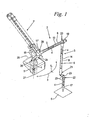
- Fig. 1 shows in a perspective view a laser system embodied in accordance with the invention, comprising a laser source 1 and a manually guided articulated arm 2.
- the articulated arm 2 comprises a stationary support 24 that is pivotable by means of a pivot joint 26 about a vertical pivot axis 27; a first arm section 13 and a second arm section 14; an articulated arm section 22; and a hand piece 17.
- the first arm section 13 is supported by means of a pivot joint 28 with a horizontal pivot axis 25 on the stationary support 24.
- an additional pivot joint 19 is provided with which the second arm section 14 is pivotably supported on the first arm section 13.
- the hand piece 17 is arranged in the area of the free end 21 of the second arm section 14.
- the articulated arm section 22 is arranged that comprises at least two, in the illustrated embodiment three, angle pieces 23 to provide free movement of the hand piece 17.
- the articulated arm referenced by reference numeral 2 and shown in solid lines, is illustrated in an angular position that is provided for operation.
- the articulated arm 2 can be pivoted back and forth between its operating position and a rest position in which the articulated arm is identified by reference numeral 2'.
- the articulated arm 2' rests with its hand piece 17' in the indicated support device 18.
- the articulated arm 2 can also be manually pivoted as a whole about the vertical pivot axis 27. In neutral angle, the articulated arm 2 can be moved from its illustrated operating position into the rest position indicated by 2' and placed onto the support device 18.
- a laser source 1 In operation of the illustrated laser system, a laser source 1 generates a laser beam that is indicated by arrows 4 and is guided along an optical path 5 in the articulated arm 2 to the target location 6.
- the articulated arm 2 has an optical arrangement 3 that will be explained in detail in connection with Figs. 3 and 4 . It comprises two optical cells 8, illustrated in dashed lines; the arm section 13 and the arm section 14 each have one of the optical cells 8 arranged therein.
- the optical arrangement 3 comprises angled mirrors, not illustrated, in the articulations and the angle members 23 of the articulated arm 2 as well as input window 9, output window 10, convergent lenses 11, 12, and lenses 29, 30 of the hand piece 17, as illustrated in Figs. 3 and 4 .
- the laser source 1 is a pulsed high-power solid-state laser with a pulse energy of at least 200 mJ, preferably at least 400 mJ, and in particular at least 800 mJ.
- the laser source 1 is configured as a Q-switched laser with technology of variable rate reflectivity and unstable resonator concept.
- the articulated arm 2 including its hand piece 17 is configured for a medical application. However, configurations and applications of the laser source 1 and of the articulated arm 2 different from medical applications can be expedient.
- Fig. 2 shows in a schematic illustration an optical arrangement 3 with optical path 5 in accordance with the prior art.
- the indicated laser source 1 generates at the output side of its correlated output mirror 38 a laser beam 4 with circular cross-section.
- the energy distribution in this circular cross-section is at least approximately constant so that a top hat-shaped beam profile 16 results.
- the bundle of approximately parallel rays of the laser beam 4 is focused in a hand piece, comparable to the hand piece 17 according to Fig. 1 , by means of schematically illustrated lenses 29, 30 to the desired diameter and guided to the target location 6.
- a central beam 31 as well as two marginal beams 32, 33 are shown in the illustration.
- its lensing properties are subject to change; this is illustrated by central rays 31', 31 " as well as by marginal rays 32', 32", 33', 33''.
- the beam diameter is limited with beams 32" and 33' in case of low laser rod lensing and with beams 32' and 33" in case of strong laser rod lensing. It can be seen that the diverging central rays 31', 31" and the marginal rays 32', 32", 33', 33 " are guided by means of the optical arrangement 3 according to the prior art to the target location 6.
- the beam divergence influences the beam diameter at the target location 6.
- a non-constant beam profile 16' results at the target location 6, that is wave-shaped in cross-section and, in a projection onto the target location 6, is an arrangement of concentric rings with an energy distribution that is non-uniform in the radial direction.
- Fig. 3 shows in a schematic illustration the optical arrangement 3 with the optical path 5 of the laser system according to the invention shown in Fig. 1 , wherein, for clarity of illustration, only one of the two optical cells 8 is illustrated. It can be expedient to provide only a single optical cell 8 in one of the two arm sections 13, 14. Inasmuch as the articulated arm 2 according to Fig. 1 has more than two arm sections 13, 14, it can be advantageous to provide each of these arm sections with an optical cell 8, respectively.
- the laser source 1 comprises a laser rod with an output mirror 38; at its output side a beam profile 16 identical to the arrangement of Fig. 2 is generated.
- a plane 15 with an at least approximately invariable beam profile 16 is generated in which the diameter of the laser beam 4, despite changing pumping parameters, is essentially constant.
- the plane 15 is approximately located at the location of the output mirror 38. In case of a stable resonator configuration, this plane 15 is located within the laser rod or in an opening delimiting the beam in the resonator.
- the optical arrangement 3 arranged at the output side of the output mirror 38 comprises in addition to the lenses 29, 30 two schematically indicated convergent lenses 11, 12, between which the optical cell 8 with its input window 9 and output window 10 is arranged.
- the beam path according to the invention is represented by rays 31, 32, 33 in order to better understand the optical scheme.
- the convergent lens 11 arranged upstream in the direction of the beam extension focuses the laser beam 4 in such a way, that the central ray 31 and the marginal rays 32, 33, including the diverging central rays 31', 31" and marginal rays 32', 33", 33', 33 " , cross at least approximately at a crossing point.
- the laser beam 4 in comparison to the beam profile 16 at the input side, has a characteristic beam waist with significantly reduced beam diameter in which a correspondingly increased power density is present.
- the cross-section of the laser beam 4 widens until it enters the downstream convergent lens 12.
- the convergent lens 12 arranged in the beam direction behind the focal point 7 transmits the laser beam 4 at its output side so as to have a beam path that is at least approximately parallel or slightly convergent.
- This beam path is focused in the downstream lenses 29, 30 within the hand piece 17 ( Fig. 1 ) to the desired beam diameter and guided to the target location 6.
- the lenses 29, 30 can have a variably adjustable spacing relative to one another so that a zoom function of the hand piece 17 ( Fig. 1 ) results by means of which the beam diameter at the target location 6 can be adjusted.
- the illustrated configuration of the optical arrangement 3 with the two convergent lenses 11, 12 and the intermediately positioned focal point 7 has the effect, that the plane 15 with the at least approximately invariable beam profile 16 is imaged on the target location 6.
- the diverging central rays 31', 31" and marginal rays 32', 32", 33', 33", emerging from exemplary points of the plane 15, are guided at least approximately to the same corresponding point on the target location 6 as the correlated central ray 31 and the correlated marginal rays 32, 33.
- This optically sharp image of the plane 15 at the target location 6 has the effect that the input-side top hat beam profile 16 is imaged in such a way on the target location 6, that at this location a top hat-shaped beam profile 16' is produced, changed only with regard to its diameter and having at least approximately constant energy distribution.
- Varying lensing properties of the laser source 1 under operating conditions, as represented by marginal rays 32', 32 ", 33', 33" do not result in a change of beam diameter at the target location 6.
- the disadvantageous prior art effects ( Fig. 2 ) of divergence and diameter variance of the laser beam 4 are thus eliminated.
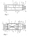
- the optical cell 8 arranged in the optical path 5 is essentially cylindrical and comprises a tubular circumferential wall 39.
- the input window 9 and the output window 10 are gas-tightly inserted into the two end faces of the circumferential wall 39.
- the optical cell 8 or its interior are sealed to be gas-tight.
- the interior of the optical cell 8 has a gas fill with an energy threshold for ionization or plasma generation that is increased in comparison to that of ambient air.
- a suitable gas that is different from ambient air can be selected.
- the optical cell 8 contains air at reduced pressure relative to the standard atmosphere.
- the pressure of the gas fill is in particular ⁇ 600 mbar, expediently ⁇ 400 mbar, and preferably ⁇ 200 mbar. Outside of the optical cell 8 ambient air is present. Relative to this ambient air, the reduced inner pressure of the gas fill within the optical cell 8 leads to the aforementioned increased energy threshold, as described infra in more detail in connection with Fig. 6 .
- the optical path 5 extends through ambient air in which also the convergent lenses 11, 12 are arranged.
- the comparatively great beam diameter does not have a sufficient power density in order to generate plasma in the ambient air. An optical impairment is therefore not to be expected.
- the laser beam 4 After the laser beam 4 has passed through the first convergent lens 11, the laser beam 4 passes through the input window 9 into the interior of the optical cell 8.
- the input window 9 that is transmissive for the laser beam 4 is formed in the illustrated embodiment as a plane-parallel glass plate, which optically does not affect the course of the laser beam 4 significantly.
- the laser beam 4 passes through the output window 10 to leave the optical cell 8 and is then guided through the ambient air and reaches the downstream convergent lens 12.
- the output window 10 is also embodied as a plane-parallel glass plate without optically affecting the course of the beam.
- the focal point 7 of laser beam 4 is positioned within the optical cell 8, i.e., in the area of the gas fill with increased energy threshold for ionization or plasma generation.
- the energy threshold of the gas fill is increased such that the increased power density of the laser beam 4 in the focal point 7 is not sufficient to effect ionization or even plasma generation of the gas fill.
- the laser beam 4 can pass through the optical cell 8 without being affected.
- Fig. 4 shows a variant of the arrangement according to Fig. 3 in which the input window 9 and the output window 10 of the optical cell 8 are each formed as a convergent lens 11 or convergent lens 12.
- the input window 9 and the output window 10 of the optical cell 8 are each formed as a convergent lens 11 or convergent lens 12.
- a separate arrangement of input window 9, output window 10, and convergent lenses 11, 12 in accordance with the illustration of Fig. 3 is not required. Instead, the function of generating the focal point 7 is directly effected by the input window 9 and the output window 10.
- the arrangement according to Fig. 4 is identical to that of Fig. 3 .
- Figs. 3 and 4 details of the articulated arm 2 according to Fig. 1 are not shown.
- further components of the optical arrangement 3 such as angled mirrors or the like are arranged outside of the respective optical cell 8; they are thus positioned in an area of the laser beam 4 where its cross-section is not reduced by the convergent lenses 11, 12. In particular thermal loading of these components is thus minimal.
- a side view of the optical cell 8 embodied in accordance with the invention is illustrated. It comprises two cylindrical tubes 34, 35 that are coaxially arranged to one another and connected by an intermediately positioned connecting piece 36. At the two free end faces of the tubes 34, 35, the input window 9 and the output window 10 are arranged.
- the connecting piece 36 has a connector 37 that is in communication with the interior of the optical cell 8.
- a vacuum pump can be connected by means of the connector 37 for reducing the interior pressure. After the desired reduced interior pressure has been adjusted, the connector 37 is sealed off so that the optical cell 8 and its interior as a whole is gas-tightly sealed. For certain applications, it can be expedient to not seal the connector 37 and to connect it instead permanently to a suitable vacuum source.
- Fig. 6 shows a diagrammatic illustration of the air pressure to be adjusted within the optical cell 8 ( Figs. 3 to 5 ) as a function of the pulse energy of the laser source 1 ( Fig. 1 ).
- the curve illustrated in the diagram of Fig. 6 illustrates the energy threshold of the exemplary embodiment of Fig. 5 at which, when surpassed, the air fill within the optical cell 8 has the tendency to generate plasma with optical breakdown in the focal point 7.
- the air pressure within the optical cell 8 is therefore to be adjusted to ⁇ 600 mbar.
- the required air pressure is therefore ⁇ 350 mbar; at a pulse energy of 800 mJ it should be ⁇ 230 mbar.
- Even pulse energies of 1.6 Joule have been achieved without optical breakdown, having an air pressure of ⁇ 180 mbar.
- the air pressure within the optical cell 8 can be significantly below the correlated threshold value for the air pressure in order to avoid disadvantageous effects by ionization even as no plasma is generated yet.
Landscapes
- Physics & Mathematics (AREA)
- Optics & Photonics (AREA)
- Engineering & Computer Science (AREA)
- Plasma & Fusion (AREA)
- Mechanical Engineering (AREA)
- Electromagnetism (AREA)
- Health & Medical Sciences (AREA)
- Life Sciences & Earth Sciences (AREA)
- Surgery (AREA)
- Biomedical Technology (AREA)
- Public Health (AREA)
- Heart & Thoracic Surgery (AREA)
- Medical Informatics (AREA)
- Molecular Biology (AREA)
- Animal Behavior & Ethology (AREA)
- General Health & Medical Sciences (AREA)
- Otolaryngology (AREA)
- Veterinary Medicine (AREA)
- Nuclear Medicine, Radiotherapy & Molecular Imaging (AREA)
- Robotics (AREA)
- Lasers (AREA)
- Laser Beam Processing (AREA)
- Laser Surgery Devices (AREA)
Abstract
Description
- The invention relates to a laser system according to the features of the preamble of
claim 1. - In technical and particularly in medical applications, the transmission of a laser beam from a laser source to a target location is realized either by a flexible light guide or along an optical path within an articulated arm. In the case of high-power lasers, the articulated arm is preferred for a couple of reasons: Fibers cannot withstand high optical power densities. When focusing a high power laser beam into a fiber, optical breakdown can occur before the beam reaches the fiber. In addition, unwanted nonlinear optical effects occur in the fibers.
- In spite of this, disadvantageous effects that increase with increasing power density can be observed for laser transmission within an articulated arm. At an appropriate power level of the laser beam, the air within the optical path can become ionized; this causes a deterioration of the beam profile at the output. At very high power densities, the ionization of air causes plasma generation that, in turn, leads to optical breakdown of the laser transmission. As soon as the plasma generation has been excited by a first part of the laser pulse, the remaining part of the laser pulse is absorbed to a large extent.
- In addition, the optical components of the articulated arm are exposed to conditions very close to damage threshold. In the case of novel Q-switched laser designs employing variable reflectivity technology in combination with the unstable resonator concept, the brightness of the output beam is even further increased, contributing particularly to thermal loading of the optical components.
- The main characteristics of the beam emerging from such a laser are exceptional uniformity of the near-field beam profile and very low beam divergence so that, in this way, diffraction-limited conditions are approached. The uniform top hat profile is one of the most desirable profiles for many applications since it offers unique light-to-matter interaction conditions across the whole beam area. However, due to the high quality of the beam in terms of the M2 parameter, any change in laser resonator conditions, in particular variations related to the laser rod lensing due to different pumping conditions, result in accentuated variations of the beam farther away from the laser output. Not only the beam diameter is influenced in this way but the beam profile quality also deteriorates in comparison to highly desired near-field top hat conditions; this is usually unacceptable for laser applications.
- To solve the problem to some extent, it is possible to trigger the laser flash-lamp at the highest repetition rate, and, by periodically activating the Q-switch cell, lower repetition rates can be obtained also. This kind of laser operation has many drawbacks. The laser pumping chamber operates at full pumping power most of the time, and this worsens problems concerning thermal load of the laser rod and related optical properties. Additionally, the lifetime of the flash-lamps is affected in this way and the overall electrical power consumption increases.
- In order to solve the problems described above, an optical arrangement of the articulated arm may be considered that is based on the imaging of the plane of invariant beam profile onto the target plane. Such an optical arrangement is based on the fact that the beam change close to the laser output mirror is small and virtually does not change with the variation of the pumping conditions. This is particularly true in the case of unstable laser resonator concept with variable reflectivity output mirrors that can be optimized in such a way that beam profile propagation characteristics very close to the plane wave diffraction on a circular aperture are produced. The beam profile in the vicinity of the laser output is therefore close to top hat shape, and changes of beam diameter due to different lensing properties of the laser rod are small. Such an imaging of the plane of invariant beam profile onto the target plane is proposed in
WO 01/78633 A2 - However,
WO 01/78633 A2 -
US 4,941,093 discloses a laser arm with an optical arrangement. The laser arm may be purged with nitrogen. FromDE 38 00 555 A1 a laser hand piece is known, which is optionally evacuated. - The present invention has therefore the object to further develop a laser system of the aforementioned kind such that its optical transmission quality is improved, in particular at very high power density of the laser beam.
- This object is solved by a laser system having the features of
claim 1. - The present invention proposes that in each of the at least two arm sections of the articulated arm at least one focal point of the laser beam is provided within the optical path, and that the optical arrangement comprises at least two optical cells each with an input window and an output window, through which cells the laser beam is passed. An optical cell is provided in each one of the at least two arm sections, respectively. The focal points are positioned within the optical cells. The optical cells have a gas fill with an energy threshold for ionization or plasma generation which threshold is increased relative to that of ambient air.
- The proposed solution means turning away from the conventional beam guiding concept, in which a beam diameter as large as possible is maintained along the entire optical path for reducing power density. The arrangement of a focus-like crossing area in the laser beam enables a configuration of the optical arrangement with exact imaging quality. Divergence phenomena or the like can be avoided almost completely, at least in approximation, at the target location; this improves the working results of the laser system.
- In the focal points the laser beam has a waist-like constriction with increased power density. Because this area is located within the optical cell, ionization or plasma generation is reliably prevented. A deterioration of the optical transmission or even an optical breakdown can be excluded even at high power density, because the increased energy threshold of the gas fill within the optical cell reliably prevents ionization or plasma generation.
- The increased energy threshold of the gas fill can be achieved in different ways. For example, it can be expedient to select a suitable gas that is different from atmospheric air. Alternatively, or in combination therewith, a reduction of the pressure of the gas fill in the optical cell relative to standard atmosphere can be advantageous. When employing vacuum, preferably air is used as an inexpensive gas fill that is available anywhere and is easy to handle technologically. The reduced pressure in the optical cell is in particular ≤ 600 mbar, expediently ≤ 400 mbar, and preferably ≤ 180 mbar; this raises effectively the ionization and plasma generation threshold. An even more reduced vacuum of the gas fill down to complete vacuum can be expedient also.
- Depending on the type of application, the optical cell can be connected permanently to a suitable vacuum source. The optical cell is gas-tightly sealed after adjusting the gas fill or the vacuum. After completion of manufacture, the sealed laser system is independent of gas sources and vacuum sources. The laser system has a simple configuration and is reliable in regard to handling.
- It can be advantageous to configure the input window and/or the output window so as to be optically neutral, i.e., in the form of a plane-parallel glass plate, for example. Preferably, the input window and/or the output window are formed by a convergent lens.
- In addition to providing the sealing function for the optical cell, windows that are configured as convergent lenses also provide an optical function. By means of the convergent lens at the input side, it is possible to generate within the optical cell the crossing point of the incoming, essentially parallel laser beam. By means of the convergent lens at the output side, the crossing beam section that widens in the output direction can be focused again such that the beam on the output side becomes parallel again, and that the cross-section of the output side remains completely on the optical path of the articulated arm. The number of optical component modules is therefore kept small.
- Different locations are conceivable within the articulated arm system for arranging the optical cell. The optical cell is arranged in an arm section of the articulated arm that can be moved in an articulated way. This provides for a sufficiently long interruption-free travel length in order to achieve an excellent imaging quality. The articulated arm has at least two arm sections that can be moved in an articulated way, and an optical cell is arranged in each one of the two arm sections. In this connection, the transmission of the laser beam is realized, at least along a significant portion of the entire transmission path, within such an optical cell. The length of the two arm sections can be matched optimally to the requirements of the user. Impractical lengths of an individual arm section that would be required otherwise for an excellent imaging quality can be avoided in this way.
- In the laser system according to the invention, the laser source is advantageously a pulsed high power laser with a pulse energy of at least 200 mJ, preferably at least 400 mJ, and in particular at least 800 mJ up to 1.6 J or greater. Preferably, the laser source is a Q-switched laser with technology of variable reflectivity and with unstable resonator concept. The laser source has a plane with at least approximately invariable beam profile wherein the optical arrangement is designed for imaging the plane with at least approximately invariable beam profile on the target location. In the configuration according to the invention, the divergence properties of the beam are no longer relevant for the beam diameter and the energy distribution within the beam diameter at the target location. The plane that is generated at the target location has in all operating states of the laser system an almost constant top hat-shaped beam profile. The focal point of the guided beam within the optical cell enables imaging of the desired uniform top hat profile on the target location without gas ionization or plasma generation within the optical path causing impairment of the intensity of the laser beam and its distribution across the beam cross-section.
- Embodiments of the invention will be explained in the following with the aid of the drawings. It is shown in:
- Fig. 1
- in a perspective overview illustration a laser system in accordance with the present invention with a laser source and an articulated arm;
- Fig. 2
- a schematic illustration of the beam path according to the prior art with beam diameter variance and non-uniform beam profile at the target location;
- Fig. 3
- a schematic illustration of the beam path in the optical arrangement of the laser system of
Fig. 1 according to the present invention, wherein the optical arrangement has the effect of creating a focal point of the laser beam within an optical cell; - Fig. 4
- a variant of the arrangement according to
Fig. 3 in which the input window and the output window of the optical cell are each formed as a convergent lens; - Fig. 5
- in a side view an embodiment of an optical cell for generating the beam path according to
Fig. 3 orFig. 4 , showing details of its constructive configuration; - Fig. 6
- in a diagrammatic illustration the course of the air pressure required within the optical cell as a function of the pulse energy of the laser beam passing through the optical cell.
-
Fig. 1 shows in a perspective view a laser system embodied in accordance with the invention, comprising alaser source 1 and a manually guided articulatedarm 2. The articulatedarm 2 comprises astationary support 24 that is pivotable by means of a pivot joint 26 about avertical pivot axis 27; afirst arm section 13 and asecond arm section 14; an articulatedarm section 22; and ahand piece 17. Thefirst arm section 13 is supported by means of a pivot joint 28 with ahorizontal pivot axis 25 on thestationary support 24. On thefree end 20 of thefirst arm section 13 positioned opposite the pivot joint 28, an additional pivot joint 19 is provided with which thesecond arm section 14 is pivotably supported on thefirst arm section 13. In the area of thefree end 21 of thesecond arm section 14, thehand piece 17 is arranged. Between thefree end 21 of thesecond arm section 14 and thehand piece 17, the articulatedarm section 22 is arranged that comprises at least two, in the illustrated embodiment three,angle pieces 23 to provide free movement of thehand piece 17. - The articulated arm, referenced by
reference numeral 2 and shown in solid lines, is illustrated in an angular position that is provided for operation. By pivot movements of the pivot joints 28, 19, the articulatedarm 2 can be pivoted back and forth between its operating position and a rest position in which the articulated arm is identified by reference numeral 2'. In its rest position, the articulated arm 2' rests with its hand piece 17' in theindicated support device 18. The articulatedarm 2 can also be manually pivoted as a whole about thevertical pivot axis 27. In neutral angle, the articulatedarm 2 can be moved from its illustrated operating position into the rest position indicated by 2' and placed onto thesupport device 18. - In operation of the illustrated laser system, a
laser source 1 generates a laser beam that is indicated byarrows 4 and is guided along anoptical path 5 in the articulatedarm 2 to thetarget location 6. For this purpose, the articulatedarm 2 has anoptical arrangement 3 that will be explained in detail in connection withFigs. 3 and4 . It comprises twooptical cells 8, illustrated in dashed lines; thearm section 13 and thearm section 14 each have one of theoptical cells 8 arranged therein. Moreover, theoptical arrangement 3 comprises angled mirrors, not illustrated, in the articulations and theangle members 23 of the articulatedarm 2 as well asinput window 9,output window 10,convergent lenses lenses hand piece 17, as illustrated inFigs. 3 and4 . By manually guiding thehand piece 17, thelaser beam 4 is guided along theoptical path 5 through the articulatedarm 2 to thetarget location 6. In the illustrated embodiment, thelaser source 1 is a pulsed high-power solid-state laser with a pulse energy of at least 200 mJ, preferably at least 400 mJ, and in particular at least 800 mJ. In this connection, thelaser source 1 is configured as a Q-switched laser with technology of variable rate reflectivity and unstable resonator concept. The articulatedarm 2 including itshand piece 17 is configured for a medical application. However, configurations and applications of thelaser source 1 and of the articulatedarm 2 different from medical applications can be expedient. -
Fig. 2 shows in a schematic illustration anoptical arrangement 3 withoptical path 5 in accordance with the prior art. The indicatedlaser source 1 generates at the output side of its correlated output mirror 38 alaser beam 4 with circular cross-section. The energy distribution in this circular cross-section is at least approximately constant so that a top hat-shapedbeam profile 16 results. The bundle of approximately parallel rays of thelaser beam 4 is focused in a hand piece, comparable to thehand piece 17 according toFig. 1 , by means of schematically illustratedlenses target location 6. - In order to explain the course of the beam, a
central beam 31 as well as twomarginal beams laser source 1, its lensing properties are subject to change; this is illustrated bycentral rays 31', 31 " as well as bymarginal rays 32', 32", 33', 33''. The beam diameter is limited withbeams 32" and 33' in case of low laser rod lensing and withbeams 32' and 33" in case of strong laser rod lensing. It can be seen that the divergingcentral rays 31', 31" and themarginal rays 32', 32", 33', 33 " are guided by means of theoptical arrangement 3 according to the prior art to thetarget location 6. With the given optical arrangement, the beam divergence influences the beam diameter at thetarget location 6. In addition, a non-constant beam profile 16' results at thetarget location 6, that is wave-shaped in cross-section and, in a projection onto thetarget location 6, is an arrangement of concentric rings with an energy distribution that is non-uniform in the radial direction. -
Fig. 3 shows in a schematic illustration theoptical arrangement 3 with theoptical path 5 of the laser system according to the invention shown inFig. 1 , wherein, for clarity of illustration, only one of the twooptical cells 8 is illustrated. It can be expedient to provide only a singleoptical cell 8 in one of the twoarm sections arm 2 according toFig. 1 has more than twoarm sections optical cell 8, respectively. Thelaser source 1 comprises a laser rod with anoutput mirror 38; at its output side abeam profile 16 identical to the arrangement ofFig. 2 is generated. Aplane 15 with an at least approximatelyinvariable beam profile 16 is generated in which the diameter of thelaser beam 4, despite changing pumping parameters, is essentially constant. In a given configuration of thelaser source 1 with an unstable resonator and variable mirror technology, theplane 15 is approximately located at the location of theoutput mirror 38. In case of a stable resonator configuration, thisplane 15 is located within the laser rod or in an opening delimiting the beam in the resonator. - The
optical arrangement 3 arranged at the output side of theoutput mirror 38 comprises in addition to thelenses convergent lenses optical cell 8 with itsinput window 9 andoutput window 10 is arranged. Although a laser beam cannot exactly be represented with ray formalism, the beam path according to the invention is represented byrays convergent lens 11 arranged upstream in the direction of the beam extension focuses thelaser beam 4 in such a way, that thecentral ray 31 and themarginal rays central rays 31', 31" andmarginal rays 32', 33", 33', 33 " , cross at least approximately at a crossing point. As a result of the divergence of thebeam 4, a focal point 7 rather than exactly a crossing point is generated. In the focal point 7, thelaser beam 4, in comparison to thebeam profile 16 at the input side, has a characteristic beam waist with significantly reduced beam diameter in which a correspondingly increased power density is present. - At the output side of the focal point 7, the cross-section of the
laser beam 4 widens until it enters the downstreamconvergent lens 12. Theconvergent lens 12 arranged in the beam direction behind the focal point 7 transmits thelaser beam 4 at its output side so as to have a beam path that is at least approximately parallel or slightly convergent. This beam path is focused in thedownstream lenses Fig. 1 ) to the desired beam diameter and guided to thetarget location 6. Thelenses Fig. 1 ) results by means of which the beam diameter at thetarget location 6 can be adjusted. - The illustrated configuration of the
optical arrangement 3 with the twoconvergent lenses plane 15 with the at least approximatelyinvariable beam profile 16 is imaged on thetarget location 6. In particular, the divergingcentral rays 31', 31" andmarginal rays 32', 32", 33', 33", emerging from exemplary points of theplane 15, are guided at least approximately to the same corresponding point on thetarget location 6 as the correlatedcentral ray 31 and the correlatedmarginal rays plane 15 at thetarget location 6 has the effect that the input-side tophat beam profile 16 is imaged in such a way on thetarget location 6, that at this location a top hat-shaped beam profile 16' is produced, changed only with regard to its diameter and having at least approximately constant energy distribution. Varying lensing properties of thelaser source 1 under operating conditions, as represented bymarginal rays 32', 32 ", 33', 33", do not result in a change of beam diameter at thetarget location 6. The disadvantageous prior art effects (Fig. 2 ) of divergence and diameter variance of thelaser beam 4 are thus eliminated. - The
optical cell 8 arranged in theoptical path 5 is essentially cylindrical and comprises a tubularcircumferential wall 39. Theinput window 9 and theoutput window 10 are gas-tightly inserted into the two end faces of thecircumferential wall 39. As a whole, theoptical cell 8 or its interior are sealed to be gas-tight. The interior of theoptical cell 8 has a gas fill with an energy threshold for ionization or plasma generation that is increased in comparison to that of ambient air. As a gas fill, a suitable gas that is different from ambient air can be selected. In the illustrated embodiment, theoptical cell 8 contains air at reduced pressure relative to the standard atmosphere. The pressure of the gas fill is in particular ≤ 600 mbar, expediently ≤ 400 mbar, and preferably ≤ 200 mbar. Outside of theoptical cell 8 ambient air is present. Relative to this ambient air, the reduced inner pressure of the gas fill within theoptical cell 8 leads to the aforementioned increased energy threshold, as described infra in more detail in connection withFig. 6 . - Outside of the
optical cell 8 theoptical path 5 extends through ambient air in which also theconvergent lenses laser beam 4 has passed through the firstconvergent lens 11, thelaser beam 4 passes through theinput window 9 into the interior of theoptical cell 8. Theinput window 9 that is transmissive for thelaser beam 4 is formed in the illustrated embodiment as a plane-parallel glass plate, which optically does not affect the course of thelaser beam 4 significantly. After passing theoptical cell 8, thelaser beam 4 passes through theoutput window 10 to leave theoptical cell 8 and is then guided through the ambient air and reaches the downstreamconvergent lens 12. Theoutput window 10 is also embodied as a plane-parallel glass plate without optically affecting the course of the beam. The focal point 7 oflaser beam 4 is positioned within theoptical cell 8, i.e., in the area of the gas fill with increased energy threshold for ionization or plasma generation. By adjusting the reduced pressure in the aforementioned way, the energy threshold of the gas fill is increased such that the increased power density of thelaser beam 4 in the focal point 7 is not sufficient to effect ionization or even plasma generation of the gas fill. Despite the increased power density in the focal point 7, thelaser beam 4 can pass through theoptical cell 8 without being affected. -
Fig. 4 shows a variant of the arrangement according toFig. 3 in which theinput window 9 and theoutput window 10 of theoptical cell 8 are each formed as aconvergent lens 11 orconvergent lens 12. In this connection, a separate arrangement ofinput window 9,output window 10, andconvergent lenses Fig. 3 is not required. Instead, the function of generating the focal point 7 is directly effected by theinput window 9 and theoutput window 10. With regard to other features and reference numerals, the arrangement according toFig. 4 is identical to that ofFig. 3 . - For clarity of illustration, in
Figs. 3 and4 details of the articulatedarm 2 according toFig. 1 are not shown. When looking atFig. 1 as well asFigs. 3 and4 , it is apparent that further components of theoptical arrangement 3 such as angled mirrors or the like are arranged outside of the respectiveoptical cell 8; they are thus positioned in an area of thelaser beam 4 where its cross-section is not reduced by theconvergent lenses - In
Fig. 5 a side view of theoptical cell 8 embodied in accordance with the invention is illustrated. It comprises twocylindrical tubes piece 36. At the two free end faces of thetubes input window 9 and theoutput window 10 are arranged. The connectingpiece 36 has aconnector 37 that is in communication with the interior of theoptical cell 8. A vacuum pump can be connected by means of theconnector 37 for reducing the interior pressure. After the desired reduced interior pressure has been adjusted, theconnector 37 is sealed off so that theoptical cell 8 and its interior as a whole is gas-tightly sealed. For certain applications, it can be expedient to not seal theconnector 37 and to connect it instead permanently to a suitable vacuum source. -
Fig. 6 shows a diagrammatic illustration of the air pressure to be adjusted within the optical cell 8 (Figs. 3 to 5 ) as a function of the pulse energy of the laser source 1 (Fig. 1 ). The curve illustrated in the diagram ofFig. 6 illustrates the energy threshold of the exemplary embodiment ofFig. 5 at which, when surpassed, the air fill within theoptical cell 8 has the tendency to generate plasma with optical breakdown in the focal point 7. At the pulse energy of 200 mJ the air pressure within theoptical cell 8 is therefore to be adjusted to ≤ 600 mbar. For a pulse energy of 400 mJ, the required air pressure is therefore ≤ 350 mbar; at a pulse energy of 800 mJ it should be ≤ 230 mbar. Even pulse energies of 1.6 Joule have been achieved without optical breakdown, having an air pressure of ≤ 180 mbar. - At a given pulse energy, it can be expedient to adjust the air pressure within the
optical cell 8 to be significantly below the correlated threshold value for the air pressure in order to avoid disadvantageous effects by ionization even as no plasma is generated yet.
Claims (7)
- A laser system comprising a laser source (1) and an articulated arm (2), wherein the articulated arm (2) has at least two arm sections (13, 14) moveable in an articulated way and comprises an optical arrangement (3) for guiding a laser beam (4) from the laser source (1) along an optical path (5) within the articulated arm (2) to a target location (6), and wherein
within the optical path (5) in each of the at least two arm sections (13, 14) at least one focal point (7) of the laser beam (4) is provided characterized in that the optical arrangement (3) comprises at least two optical cells (8) each with an input window (9) and an output window (10) for passing the laser beam (4) therethrough, wherein an optical cell (8) is provided in each one of the at least two arm sections (13, 14), respectively, wherein the focal points (7) are positioned within the optical cells (8), and wherein the optical cells (8) are sealed gas-tightly and comprise a gas fill with an energy threshold for ionization that is increased in comparison to that of ambient air. - The laser system according to claim 1,
characterized in that the gas fill of the optical cell (8) has a pressure that is reduced relative to standard atmosphere, which pressure is in particular ≤ 600 mbar, expediently ≤ 400 mbar, and preferably ≤ 180 mbar. - The laser system according to claim 2,
characterized in that the gas fill is air at reduced pressure. - The laser system according to one of the claims 1 to 3,
characterized in that the input window (9) and/or the output window (10) is a convergent lens (11, 12). - The laser system according to one of the claims 1 to 4,
characterized in that the laser source (1) is a pulsed high-energy laser with a pulse energy of at least 200 mJ, preferably at least 400 mJ, and in particular at least 800 mJ up to 1.6 J or greater. - The laser system according to one of the claims 1 to 5,
characterized in that the laser source (1) has a plane (15), in which the beam profile (16) does at least approximately not change with the variation of the pumping conditions, wherein the optical arrangement (3) is designed for imaging the plane (15) with the at least approximately invariable beam profile (16) on the target location (6). - The laser system according to one of the claims 1 to 6,
characterized in that the laser source (1) is configured as a Q-switched laser with a variable reflectivity mirror and with an unstable resonator.
Priority Applications (4)
| Application Number | Priority Date | Filing Date | Title |
|---|---|---|---|
| EP07008465A EP1985254B1 (en) | 2007-04-26 | 2007-04-26 | Laser system |
| DE602007002696T DE602007002696D1 (en) | 2007-04-26 | 2007-04-26 | laser system |
| AT07008465T ATE444718T1 (en) | 2007-04-26 | 2007-04-26 | LASER SYSTEM |
| US12/107,124 US7778306B2 (en) | 2007-04-26 | 2008-04-22 | Laser system |
Applications Claiming Priority (1)
| Application Number | Priority Date | Filing Date | Title |
|---|---|---|---|
| EP07008465A EP1985254B1 (en) | 2007-04-26 | 2007-04-26 | Laser system |
Publications (2)
| Publication Number | Publication Date |
|---|---|
| EP1985254A1 EP1985254A1 (en) | 2008-10-29 |
| EP1985254B1 true EP1985254B1 (en) | 2009-10-07 |
Family
ID=38197982
Family Applications (1)
| Application Number | Title | Priority Date | Filing Date |
|---|---|---|---|
| EP07008465A Active EP1985254B1 (en) | 2007-04-26 | 2007-04-26 | Laser system |
Country Status (4)
| Country | Link |
|---|---|
| US (1) | US7778306B2 (en) |
| EP (1) | EP1985254B1 (en) |
| AT (1) | ATE444718T1 (en) |
| DE (1) | DE602007002696D1 (en) |
Families Citing this family (16)
| Publication number | Priority date | Publication date | Assignee | Title |
|---|---|---|---|---|
| EP4272694A3 (en) | 2006-04-20 | 2024-01-03 | Sonendo, Inc. | Apparatus for treating root canals of teeth |
| US10835355B2 (en) | 2006-04-20 | 2020-11-17 | Sonendo, Inc. | Apparatus and methods for treating root canals of teeth |
| US7980854B2 (en) | 2006-08-24 | 2011-07-19 | Medical Dental Advanced Technologies Group, L.L.C. | Dental and medical treatments and procedures |
| US12114924B2 (en) | 2006-08-24 | 2024-10-15 | Pipstek, Llc | Treatment system and method |
| JP5902096B2 (en) | 2009-11-13 | 2016-04-13 | ソネンド インコーポレイテッド | Liquid jetting apparatus and method for dental treatment |
| US8749880B2 (en) | 2009-11-24 | 2014-06-10 | Applied Energetics | Off axis walk off multi-pass amplifiers |
| BR112013009708A2 (en) | 2010-10-21 | 2016-07-19 | Sonendo Inc | endodontic treatment apparatus, methods and compositions |
| US11173019B2 (en) | 2012-03-22 | 2021-11-16 | Sonendo, Inc. | Apparatus and methods for cleaning teeth |
| US10631962B2 (en) | 2012-04-13 | 2020-04-28 | Sonendo, Inc. | Apparatus and methods for cleaning teeth and gingival pockets |
| ES2883954T3 (en) | 2012-12-20 | 2021-12-09 | Sonendo Inc | Tooth and root canal cleaning appliance |
| US10363120B2 (en) | 2012-12-20 | 2019-07-30 | Sonendo, Inc. | Apparatus and methods for cleaning teeth and root canals |
| EP2991576B1 (en) | 2013-05-01 | 2022-12-28 | Sonendo, Inc. | Apparatus and system for treating teeth |
| US9877801B2 (en) | 2013-06-26 | 2018-01-30 | Sonendo, Inc. | Apparatus and methods for filling teeth and root canals |
| US10806544B2 (en) | 2016-04-04 | 2020-10-20 | Sonendo, Inc. | Systems and methods for removing foreign objects from root canals |
| USD997355S1 (en) | 2020-10-07 | 2023-08-29 | Sonendo, Inc. | Dental treatment instrument |
| USD1118938S1 (en) | 2022-09-23 | 2026-03-17 | Sonendo, Inc. | Dental console |
Family Cites Families (7)
| Publication number | Priority date | Publication date | Assignee | Title |
|---|---|---|---|---|
| AU606315B2 (en) | 1985-09-12 | 1991-02-07 | Summit Technology, Inc. | Surface erosion using lasers |
| DE3800555A1 (en) | 1988-01-12 | 1989-07-27 | Ulrich Dardenne Stiftung Ev | DEVICE FOR THE ABLATIVE PHOTODECOMPOSITION OF DENTAL RESIN SUBSTANCES BY MEANS OF A WAVELENGTH OF 193 NM ARGON / FLUORID EXCIMER LASERS AND AN APPLICATION DEVICE FOR THIS LASER LIGHTING DEVICE |
| JP2524682B2 (en) * | 1993-12-27 | 1996-08-14 | 技術研究組合医療福祉機器研究所 | Laser light guide device |
| US5394411A (en) * | 1994-02-16 | 1995-02-28 | University Of Maryland, College Park | Method for producing high intensity optical through x-ray waveguide and applications |
| US6451010B1 (en) | 2000-04-14 | 2002-09-17 | Lumenis Inc. | Zoom handpiece for laser surgery |
| JP4657103B2 (en) * | 2003-04-22 | 2011-03-23 | 株式会社小松製作所 | Two-stage laser equipment for exposure |
| US7110171B2 (en) * | 2003-10-30 | 2006-09-19 | Metal Improvement Company, Llc | Relay telescope including baffle, and high power laser amplifier utilizing the same |
-
2007
- 2007-04-26 EP EP07008465A patent/EP1985254B1/en active Active
- 2007-04-26 AT AT07008465T patent/ATE444718T1/en not_active IP Right Cessation
- 2007-04-26 DE DE602007002696T patent/DE602007002696D1/en active Active
-
2008
- 2008-04-22 US US12/107,124 patent/US7778306B2/en active Active
Also Published As
| Publication number | Publication date |
|---|---|
| US20080267247A1 (en) | 2008-10-30 |
| US7778306B2 (en) | 2010-08-17 |
| ATE444718T1 (en) | 2009-10-15 |
| EP1985254A1 (en) | 2008-10-29 |
| DE602007002696D1 (en) | 2009-11-19 |
Similar Documents
| Publication | Publication Date | Title |
|---|---|---|
| US7778306B2 (en) | Laser system | |
| US10504714B2 (en) | Dual parabolic laser driven sealed beam lamp | |
| US9941655B2 (en) | High power broadband light source | |
| US9748086B2 (en) | Laser driven sealed beam lamp | |
| US9016881B2 (en) | Beam guide and method for adjusting the opening angle of a laser beam | |
| US10186416B2 (en) | Apparatus and a method for operating a variable pressure sealed beam lamp | |
| WO2020177343A1 (en) | Frequency conversion apparatus for hollow-core anti-resonant optical fiber | |
| WO2016098543A1 (en) | Extreme ultraviolet light generation device | |
| EP3657237A1 (en) | Transmission adaptive optical system | |
| JP7097224B2 (en) | Laser deflector and laser machining equipment | |
| CN119072655A (en) | Laser frequency conversion with UV damage mitigation | |
| CN117199977A (en) | A proportionally adjustable femtosecond laser pulse self-compression device and method thereof | |
| JP6978718B2 (en) | Laser drive light source | |
| EP3533079A1 (en) | Apparatus and a method for operating a variable pressure sealed beam lamp | |
| CN117891082B (en) | A long-distance laser shaping detection lighting device | |
| US20260093098A1 (en) | Apparatus for focusing a high-power laser | |
| KR20250162115A (en) | Handpiece type laser resonator | |
| WO2025237694A1 (en) | Compact laser beam generating device, apparatus including such device and method for generating a laser beam | |
| CN120855041A (en) | A multi-pass cavity laser pulse compression device and a femtosecond laser system using the same | |
| JPH0651237A (en) | Laser light transmission device | |
| US20200227881A1 (en) | Laser beam irradiation apparatus and laser beam irradiation system | |
| WO2016148608A1 (en) | Source of broadband optical radiation with high brightness |
Legal Events
| Date | Code | Title | Description |
|---|---|---|---|
| PUAI | Public reference made under article 153(3) epc to a published international application that has entered the european phase |
Free format text: ORIGINAL CODE: 0009012 |
|
| 17P | Request for examination filed |
Effective date: 20080319 |
|
| AK | Designated contracting states |
Kind code of ref document: A1 Designated state(s): AT BE BG CH CY CZ DE DK EE ES FI FR GB GR HU IE IS IT LI LT LU LV MC MT NL PL PT RO SE SI SK TR |
|
| AX | Request for extension of the european patent |
Extension state: AL BA HR MK RS |
|
| 17Q | First examination report despatched |
Effective date: 20090223 |
|
| GRAP | Despatch of communication of intention to grant a patent |
Free format text: ORIGINAL CODE: EPIDOSNIGR1 |
|
| AKX | Designation fees paid |
Designated state(s): AT BE BG CH CY CZ DE DK EE ES FI FR GB GR HU IE IS IT LI LT LU LV MC MT NL PL PT RO SE SI SK TR |
|
| GRAS | Grant fee paid |
Free format text: ORIGINAL CODE: EPIDOSNIGR3 |
|
| GRAA | (expected) grant |
Free format text: ORIGINAL CODE: 0009210 |
|
| AK | Designated contracting states |
Kind code of ref document: B1 Designated state(s): AT BE BG CH CY CZ DE DK EE ES FI FR GB GR HU IE IS IT LI LT LU LV MC MT NL PL PT RO SE SI SK TR |
|
| REG | Reference to a national code |
Ref country code: GB Ref legal event code: FG4D |
|
| REG | Reference to a national code |
Ref country code: CH Ref legal event code: EP |
|
| REG | Reference to a national code |
Ref country code: IE Ref legal event code: FG4D |
|
| REF | Corresponds to: |
Ref document number: 602007002696 Country of ref document: DE Date of ref document: 20091119 Kind code of ref document: P |
|
| PG25 | Lapsed in a contracting state [announced via postgrant information from national office to epo] |
Ref country code: SI Free format text: LAPSE BECAUSE OF FAILURE TO SUBMIT A TRANSLATION OF THE DESCRIPTION OR TO PAY THE FEE WITHIN THE PRESCRIBED TIME-LIMIT Effective date: 20091007 |
|
| NLV1 | Nl: lapsed or annulled due to failure to fulfill the requirements of art. 29p and 29m of the patents act | ||
| LTIE | Lt: invalidation of european patent or patent extension |
Effective date: 20091007 |
|
| PG25 | Lapsed in a contracting state [announced via postgrant information from national office to epo] |
Ref country code: IS Free format text: LAPSE BECAUSE OF FAILURE TO SUBMIT A TRANSLATION OF THE DESCRIPTION OR TO PAY THE FEE WITHIN THE PRESCRIBED TIME-LIMIT Effective date: 20100207 Ref country code: ES Free format text: LAPSE BECAUSE OF FAILURE TO SUBMIT A TRANSLATION OF THE DESCRIPTION OR TO PAY THE FEE WITHIN THE PRESCRIBED TIME-LIMIT Effective date: 20100118 Ref country code: FI Free format text: LAPSE BECAUSE OF FAILURE TO SUBMIT A TRANSLATION OF THE DESCRIPTION OR TO PAY THE FEE WITHIN THE PRESCRIBED TIME-LIMIT Effective date: 20091007 Ref country code: SE Free format text: LAPSE BECAUSE OF FAILURE TO SUBMIT A TRANSLATION OF THE DESCRIPTION OR TO PAY THE FEE WITHIN THE PRESCRIBED TIME-LIMIT Effective date: 20091007 Ref country code: PT Free format text: LAPSE BECAUSE OF FAILURE TO SUBMIT A TRANSLATION OF THE DESCRIPTION OR TO PAY THE FEE WITHIN THE PRESCRIBED TIME-LIMIT Effective date: 20100208 Ref country code: LT Free format text: LAPSE BECAUSE OF FAILURE TO SUBMIT A TRANSLATION OF THE DESCRIPTION OR TO PAY THE FEE WITHIN THE PRESCRIBED TIME-LIMIT Effective date: 20091007 |
|
| PG25 | Lapsed in a contracting state [announced via postgrant information from national office to epo] |
Ref country code: PL Free format text: LAPSE BECAUSE OF FAILURE TO SUBMIT A TRANSLATION OF THE DESCRIPTION OR TO PAY THE FEE WITHIN THE PRESCRIBED TIME-LIMIT Effective date: 20091007 Ref country code: LV Free format text: LAPSE BECAUSE OF FAILURE TO SUBMIT A TRANSLATION OF THE DESCRIPTION OR TO PAY THE FEE WITHIN THE PRESCRIBED TIME-LIMIT Effective date: 20091007 |
|
| PG25 | Lapsed in a contracting state [announced via postgrant information from national office to epo] |
Ref country code: AT Free format text: LAPSE BECAUSE OF FAILURE TO SUBMIT A TRANSLATION OF THE DESCRIPTION OR TO PAY THE FEE WITHIN THE PRESCRIBED TIME-LIMIT Effective date: 20091007 Ref country code: BE Free format text: LAPSE BECAUSE OF FAILURE TO SUBMIT A TRANSLATION OF THE DESCRIPTION OR TO PAY THE FEE WITHIN THE PRESCRIBED TIME-LIMIT Effective date: 20091007 |
|
| PG25 | Lapsed in a contracting state [announced via postgrant information from national office to epo] |
Ref country code: NL Free format text: LAPSE BECAUSE OF FAILURE TO SUBMIT A TRANSLATION OF THE DESCRIPTION OR TO PAY THE FEE WITHIN THE PRESCRIBED TIME-LIMIT Effective date: 20091007 Ref country code: DK Free format text: LAPSE BECAUSE OF FAILURE TO SUBMIT A TRANSLATION OF THE DESCRIPTION OR TO PAY THE FEE WITHIN THE PRESCRIBED TIME-LIMIT Effective date: 20091007 Ref country code: EE Free format text: LAPSE BECAUSE OF FAILURE TO SUBMIT A TRANSLATION OF THE DESCRIPTION OR TO PAY THE FEE WITHIN THE PRESCRIBED TIME-LIMIT Effective date: 20091007 Ref country code: BG Free format text: LAPSE BECAUSE OF FAILURE TO SUBMIT A TRANSLATION OF THE DESCRIPTION OR TO PAY THE FEE WITHIN THE PRESCRIBED TIME-LIMIT Effective date: 20100107 Ref country code: RO Free format text: LAPSE BECAUSE OF FAILURE TO SUBMIT A TRANSLATION OF THE DESCRIPTION OR TO PAY THE FEE WITHIN THE PRESCRIBED TIME-LIMIT Effective date: 20091007 |
|
| PLBE | No opposition filed within time limit |
Free format text: ORIGINAL CODE: 0009261 |
|
| STAA | Information on the status of an ep patent application or granted ep patent |
Free format text: STATUS: NO OPPOSITION FILED WITHIN TIME LIMIT |
|
| PG25 | Lapsed in a contracting state [announced via postgrant information from national office to epo] |
Ref country code: SK Free format text: LAPSE BECAUSE OF FAILURE TO SUBMIT A TRANSLATION OF THE DESCRIPTION OR TO PAY THE FEE WITHIN THE PRESCRIBED TIME-LIMIT Effective date: 20091007 Ref country code: CZ Free format text: LAPSE BECAUSE OF FAILURE TO SUBMIT A TRANSLATION OF THE DESCRIPTION OR TO PAY THE FEE WITHIN THE PRESCRIBED TIME-LIMIT Effective date: 20091007 |
|
| 26N | No opposition filed |
Effective date: 20100708 |
|
| PG25 | Lapsed in a contracting state [announced via postgrant information from national office to epo] |
Ref country code: GR Free format text: LAPSE BECAUSE OF FAILURE TO SUBMIT A TRANSLATION OF THE DESCRIPTION OR TO PAY THE FEE WITHIN THE PRESCRIBED TIME-LIMIT Effective date: 20100108 |
|
| PG25 | Lapsed in a contracting state [announced via postgrant information from national office to epo] |
Ref country code: MC Free format text: LAPSE BECAUSE OF NON-PAYMENT OF DUE FEES Effective date: 20100430 |
|
| PG25 | Lapsed in a contracting state [announced via postgrant information from national office to epo] |
Ref country code: IE Free format text: LAPSE BECAUSE OF NON-PAYMENT OF DUE FEES Effective date: 20100426 |
|
| PG25 | Lapsed in a contracting state [announced via postgrant information from national office to epo] |
Ref country code: IT Free format text: LAPSE BECAUSE OF NON-PAYMENT OF DUE FEES Effective date: 20100426 |
|
| PG25 | Lapsed in a contracting state [announced via postgrant information from national office to epo] |
Ref country code: MT Free format text: LAPSE BECAUSE OF FAILURE TO SUBMIT A TRANSLATION OF THE DESCRIPTION OR TO PAY THE FEE WITHIN THE PRESCRIBED TIME-LIMIT Effective date: 20091007 |
|
| REG | Reference to a national code |
Ref country code: CH Ref legal event code: PL |
|
| PG25 | Lapsed in a contracting state [announced via postgrant information from national office to epo] |
Ref country code: LI Free format text: LAPSE BECAUSE OF NON-PAYMENT OF DUE FEES Effective date: 20110430 Ref country code: CH Free format text: LAPSE BECAUSE OF NON-PAYMENT OF DUE FEES Effective date: 20110430 |
|
| PG25 | Lapsed in a contracting state [announced via postgrant information from national office to epo] |
Ref country code: CY Free format text: LAPSE BECAUSE OF FAILURE TO SUBMIT A TRANSLATION OF THE DESCRIPTION OR TO PAY THE FEE WITHIN THE PRESCRIBED TIME-LIMIT Effective date: 20091007 |
|
| PG25 | Lapsed in a contracting state [announced via postgrant information from national office to epo] |
Ref country code: HU Free format text: LAPSE BECAUSE OF FAILURE TO SUBMIT A TRANSLATION OF THE DESCRIPTION OR TO PAY THE FEE WITHIN THE PRESCRIBED TIME-LIMIT Effective date: 20100408 Ref country code: LU Free format text: LAPSE BECAUSE OF NON-PAYMENT OF DUE FEES Effective date: 20100426 |
|
| PG25 | Lapsed in a contracting state [announced via postgrant information from national office to epo] |
Ref country code: TR Free format text: LAPSE BECAUSE OF FAILURE TO SUBMIT A TRANSLATION OF THE DESCRIPTION OR TO PAY THE FEE WITHIN THE PRESCRIBED TIME-LIMIT Effective date: 20091007 |
|
| REG | Reference to a national code |
Ref country code: FR Ref legal event code: PLFP Year of fee payment: 10 |
|
| REG | Reference to a national code |
Ref country code: FR Ref legal event code: PLFP Year of fee payment: 11 |
|
| REG | Reference to a national code |
Ref country code: FR Ref legal event code: PLFP Year of fee payment: 12 |
|
| PGFP | Annual fee paid to national office [announced via postgrant information from national office to epo] |
Ref country code: DE Payment date: 20250422 Year of fee payment: 19 |
|
| PGFP | Annual fee paid to national office [announced via postgrant information from national office to epo] |
Ref country code: GB Payment date: 20250418 Year of fee payment: 19 |
|
| PGFP | Annual fee paid to national office [announced via postgrant information from national office to epo] |
Ref country code: IT Payment date: 20250424 Year of fee payment: 19 |
|
| PGFP | Annual fee paid to national office [announced via postgrant information from national office to epo] |
Ref country code: FR Payment date: 20250424 Year of fee payment: 19 |