EP1984986B1 - Squib connector with improved cover connection - Google Patents
Squib connector with improved cover connection Download PDFInfo
- Publication number
- EP1984986B1 EP1984986B1 EP07794317.3A EP07794317A EP1984986B1 EP 1984986 B1 EP1984986 B1 EP 1984986B1 EP 07794317 A EP07794317 A EP 07794317A EP 1984986 B1 EP1984986 B1 EP 1984986B1
- Authority
- EP
- European Patent Office
- Prior art keywords
- section
- snap
- lock
- cover
- base
- Prior art date
- Legal status (The legal status is an assumption and is not a legal conclusion. Google has not performed a legal analysis and makes no representation as to the accuracy of the status listed.)
- Not-in-force
Links
- 238000013461 design Methods 0.000 description 3
- 230000013011 mating Effects 0.000 description 3
- 238000002788 crimping Methods 0.000 description 2
- 238000012986 modification Methods 0.000 description 2
- 230000004048 modification Effects 0.000 description 2
- 230000009467 reduction Effects 0.000 description 2
- 229910000859 α-Fe Inorganic materials 0.000 description 2
- 238000011161 development Methods 0.000 description 1
- 230000018109 developmental process Effects 0.000 description 1
- 230000000694 effects Effects 0.000 description 1
- 238000010348 incorporation Methods 0.000 description 1
- 239000003999 initiator Substances 0.000 description 1
- 238000004519 manufacturing process Methods 0.000 description 1
- 239000000463 material Substances 0.000 description 1
- 239000002991 molded plastic Substances 0.000 description 1
- 239000002861 polymer material Substances 0.000 description 1
- 238000012360 testing method Methods 0.000 description 1
- 230000007704 transition Effects 0.000 description 1
Images








Classifications
-
- H—ELECTRICITY
- H01—ELECTRIC ELEMENTS
- H01R—ELECTRICALLY-CONDUCTIVE CONNECTIONS; STRUCTURAL ASSOCIATIONS OF A PLURALITY OF MUTUALLY-INSULATED ELECTRICAL CONNECTING ELEMENTS; COUPLING DEVICES; CURRENT COLLECTORS
- H01R13/00—Details of coupling devices of the kinds covered by groups H01R12/70 or H01R24/00 - H01R33/00
- H01R13/46—Bases; Cases
- H01R13/502—Bases; Cases composed of different pieces
- H01R13/506—Bases; Cases composed of different pieces assembled by snap action of the parts
-
- H—ELECTRICITY
- H01—ELECTRIC ELEMENTS
- H01R—ELECTRICALLY-CONDUCTIVE CONNECTIONS; STRUCTURAL ASSOCIATIONS OF A PLURALITY OF MUTUALLY-INSULATED ELECTRICAL CONNECTING ELEMENTS; COUPLING DEVICES; CURRENT COLLECTORS
- H01R13/00—Details of coupling devices of the kinds covered by groups H01R12/70 or H01R24/00 - H01R33/00
- H01R13/62—Means for facilitating engagement or disengagement of coupling parts or for holding them in engagement
- H01R13/627—Snap or like fastening
- H01R13/6271—Latching means integral with the housing
Definitions
- the invention relates to an electrical connector and, more particularly, to a connection of a cover to a housing of an electrical connector.
- U.S. Patent No. 6,799,999 discloses a filtered electrical connector having a cover which is snap-lock connected to a housing.
- the electrical connector is a Squib connector used in an automobile air bag system.
- Such electrical connectors are also known from US 6 250 952 or EP 1 339 140 .
- US 6250952 discloses an igniter connector with precised position of the electrical contacts in the insulative housing and the EP 1339140 discloses an easy electrical connector assembly with noise reduction effect and less damage of ferrite members.
- the connector 1 includes a housing cover 3 which is snap-lock connected to the housing base 2.
- the cover 3 has a rear section with two holes 4 at opposite sides of the rear section.
- the cover also has a front section with a hole 5.
- the housing base 2 has three snap-lock projections 6, 7 which snap into the holes 4, 5 when the cover 3 is attached to the base 2.
- the housing and cover provide a strain relieve feature to the electrical wires 8 by clamping on the wires.
- US-A-6250952 discloses an electrical connector according to the preamble of claim 1, an electrical connector housing according to the preamble of claim 6 and an electrical connector according to the preamble of claim 11.
- an electrical connector includes a base, a cover, and an electrical terminal.
- the base includes a front section and a rear section.
- the base includes at least one terminal receiving area.
- the front section includes a first portion of the terminal receiving area.
- the first portion of the terminal receiving area extends in a first direction.
- the rear section includes a first snap-lock ledge and a second portion of the terminal receiving area.
- the second portion of the terminal receiving area extends in a second direction.
- the first snap-lock ledge extends along a majority of a length of the rear section.
- the cover includes a top section and a first lateral side section extending from the top section.
- the first lateral side section receives the first snap-lock ledge.
- the electrical terminal is mounted between the base and the cover.
- an electrical connector housing includes a housing base and a housing cover.
- the housing base comprises a front section and a rear section.
- the front section is adapted to receive a first portion of a terminal.
- the rear section extends from the front section in a general cantilever fashion.
- the rear section is adapted to receive a second portion of the terminal.
- the housing cover has a rear section with a general U-shaped cross-section.
- the housing cover is attached to the housing base.
- the housing cover includes opposing lateral side sections. Each of the opposing lateral side sections includes a snap-lock groove. The snap-lock grooves are configured to provide a clamping force along a majority of a length of the rear section.
- an electrical connector according to claim 11 is disclosed.
- the electrical connector includes a base, a cover, and an electrical terminal.
- the base includes a front section and a rear section.
- the base includes at least one terminal receiving area.
- the front section includes a first portion of the terminal receiving area. The first portion extends in a first direction.
- the rear section includes a second portion of the terminal receiving area. The second portion extends in a second direction.
- the cover is connected to the base.
- the cover includes a top section, opposing lateral side sections, and bend sections.
- the bend sections connect the lateral side sections to the top section.
- the lateral side sections include a snap-lock hole.
- the bend sections extend from the snap-lock hole to a rear side of the base.
- the electrical terminal is mounted between the base and the cover.
- FIGs. 3 and 4 there are shown perspective views of an electrical connector housing base 10 and housing cover 12 incorporating features of the invention.
- the invention will be described with reference to the exemplary embodiments shown in the drawings, it should be understood that the invention can be embodied in many alternate forms of embodiments.
- any suitable size, shape or type of elements or materials could be used.
- the base 10 and cover 12 are used in conjunction with electrical contacts or terminals, and perhaps other members, such as ferrite tubes, as described in U.S. Patent No. 6,799,999 to form a Squib electrical connector, such as for use in an automobile air bag system.
- the base 10 and cover 12 are preferably each a one piece member made of molded plastic or polymer material.
- the base 10 comprises a front section 14 and a rear section 16.
- the front section 14 is adapted to be plugged into a socket of another member, such as an air bag initiator socket or another mating electrical connector.
- the front section 14 comprises snap-lock latches 18 for snap-lock connecting to the mating socket, two channel holes 20 for receiving female sections of the electrical contacts, and a cover snap-lock wedge 22 at the front of the front section proximate the top of the front section.
- Each of the channel holes 20 (which may also be referred to as first portions of a terminal receiving area) extends in a first direction parallel to a front section 14 mating direction.
- the rear section 16 has a rear side 24 with two grooved areas 26 therethrough.
- the rear section 16 extends from the front section 14 in a general cantilever fashion.
- the rear section has two channel areas 28 extending from the two grooved areas 26 to the two channel holes 20 in the front section 14.
- An interior wall 30 is provided separating the channel areas 28 from each other.
- Lateral side walls 32 are provided at outer lateral sides of the channel areas 28.
- the exterior sides of the lateral side walls 32 each comprise a snap-lock ledge 34 which extends substantially the entire length of the length of the channel areas 28, such as more than a majority of the length.
- the snap-lock ledges 34 each have a generally triangular shape with a sloped or angled top side, starting at about the top of the walls 32, and a substantially horizontal bottom side. Front and rear ends of the snap-lock ledges 34 are bounded by front and rear portions 36, 38 of the rear section 16.
- the channel areas (or second portions of the terminal receiving area) 28 are adapted to receive rear connections sections of the electrical contacts therein and portions of the electrical wires.
- the channel areas 28 extend in a second direction which is substantially perpendicular to the first direction of the channel holes 20.
- the portions of the electrical wires are attached, such as by crimping, to the rear connections sections of the electrical contacts.
- the electrical wires extend into the channel areas 28 at the grooved areas 26 between the cover 12 and the base 10.
- the housing cover 12 generally comprises a front section 40 and a rear section 42.
- the front section 40 generally comprises a front snap-lock section 44 with a hole 46 for snap-lock connection to the cover snap-lock wedge 22 at the top front side of the front section 14 of the base 10.
- the front section 40 has a portion 48 for substantially covering over the channel holes 20.
- the rear section 42 of the cover 12 has a top section 49, two lateral side snap-lock sections 50 extending downward from opposite lateral sides of the top section 49, and two wire contact sections 52 extending downward from the rear side of the top section 49.
- the top section 49 and the two lateral side snap-lock sections form a general U-shaped cross-section.
- the lateral side snap-lock sections 50 each comprise an interior facing groove 54.
- the snap-lock sections 50 are adapted to snap-lock connect to the snap-lock ledges 34 on the housing base 10.
- the grooves 54 extend the entire length of the rear section with open front and rear ends. Thus, the grooves 54 can receive the entire lengths of the snap-lock ledges 34 therein. This provides an increased area of latching contact (or clamping force) between the cover 12 and the base 10 than previously provided in other conventional Squib connectors.
- the two wire contact sections 52 have generally grooved bottom surfaces 56 for contacting the electrical wires.
- the surfaces 56 and the grooved areas 26 clamp the wires therebetween. This forms a strain relieve for the wires. Because of the increased area of latching contact between the cover 12 and the base 10 at the grooves 54 and snap-lock ledges 34, greater clamping force can be provided on the wires by the base 10 and cover 12.
- the snap-lock sections 50 are provided with the elongated grooves or slots 54 rather than through holes as in the prior art.
- the elongated grooves or slots 54 do not completely extend through the thickness of the snap-lock sections 50. Because the elongated grooves or slots 54 do not completely extend through the thickness of the snap-lock sections 50, the strength of the snap-lock sections 50 are stronger than in the prior art (lateral snap-lock connection sections having through holes therethrough).
- the housing and cover can provide an increased resistance to withstand a 90° pull force applied to the terminal wires.
- the invention allows improving the resistance of the connector to the increased pull force while preserving a basic conventional Squib connector design and overall size, such as a ABX-3 UC Assembly manufactured by FCI USA, Inc as shown in Figs 1 and 2 .
- Fig. 8 shows a perspective view of an electrical connector 58 comprising the cover 90, base 60, two wires 8 and two electrical contacts 88.
- FIG. 9-12 perspective views of a housing base and Figs. 13-17 views of a housing cover of an alternate embodiment of a Squib air bag electrical connector is shown. Similar to the first embodiment shown in Figs. 3-8 , the second embodiment is sized and shaped to occupy the same area and shape as the conventional electrical connector shown in Fig. 1 .
- This allows the new connectors to be used instead of the connector 1 without having to be concerned about the surrounding available area and surrounding components which the connector will be located near, such as an automobile steering wheel housing and other components in an automobile steering wheel, or a vehicle occupant seat, or portions of a vehicle frame near the head of an occupant for example.
- the new connectors described herein have the same real estate and overall exterior size as the conventional connector 1. This allows a connector incorporating the invention to be used without having to redesign these surrounding components or the surrounding area.
- the housing base 60 has a front section 62 and a rear section 64.
- the front section 62 is identical to the front section of the housing base shown in Fig. 1 .
- the rear section 64 generally comprises a rear side 66 with two grooved areas 68 therethrough.
- the rear section has two channel areas 70 extending from the two grooved areas 68 to the two channel holes 20 in the front section 62.
- An interior wall 72 is provided separating the channel areas 70 from each other.
- Lateral side walls 74 are provided at outer lateral sides of the channel areas 70.
- each snap-lock ledge 76 each have a generally triangular shape with a sloped or angled top side 77 and a substantially horizontal bottom side 79. Unlike the embodiment shown in Figs. 3 and 5 , each snap-lock ledge 76 does not extend substantially the entire length of the rear section. Instead, each snap-lock ledge has a length about the same as the snap-lock ledge 6 used in the conventional connector shown in Fig. 1 .
- the snap-lock ledge 76 has a substantially same size and shape as the snap-lock ledge 6 except for top side recesses 80.
- the height X 2 of the side walls 74 is lower than the height X 1 of the side walls of the base in the connector 1 shown in Fig. 1 .
- the top 82 of each snap-lock ledge 76 in the embodiment shown in Figs. 9-12 extends above the top side 83 of the lateral side walls 74.
- the exterior side walls 74 each also comprise a snap-lock pocket 78 located beneath the bottom side of the snap-lock ledges 76.
- the pockets 78 extend into the side walls 74.
- the rear end of the lateral side walls 74 each comprise an outward projecting finger (or lateral leg) 84.
- the finger 84 does not extend the entire height of the lateral side wall. Instead, the fingers 84 projection from a bottom portion of the lateral side walls. This is different from housing base of the conventional connector shown in Fig. 1 which has a rear section that projects outward from the lateral side wall the entire height of the lateral side wall.
- rear extension areas 86 are provided above the fingers 84 which can accommodate portions 132 of the cover 90 which were not provided in the prior art.
- the rear extension areas 86 terminate, or are flush, at the rear side 66 of the rear section 64.
- the channel areas 70 are adapted to receive rear connections sections of the electrical contacts therein and portions of the electrical wires.
- the portions of the electrical wires are attached, such as by crimping, to the rear connections sections of the electrical contacts.
- the electrical wires extend into the channel areas 70 at the grooved areas 68 between the cover 90 and the base 60.
- the height of the interior wall 72 is substantially the same as the height of the interior wall in the conventional connector shown in Fig. 1 .
- the height of the interior wall 72 is higher than the height of the lateral side walls 74.
- the height of the rear side 66 is lower than the height of the rear side of the housing base of the conventional connector shown in Fig. 1 .
- the height of the interior wall 72 is higher than the height of the rear side 66.
- the cover 90 comprises a front section 92 and a rear section 94.
- the front section 92 is substantially the same as the front section of the housing cover 3 of the conventional connector shown in Fig. 1 .
- the front section 92 comprises a deflectable snap-lock latch section 96 with a hole 98 adapted to snap-lock connect to the snap-lock projection 100 (see Fig. 9 ) at the front of the housing base 60.
- the rear section 94 generally comprises a top section 102, two lateral side snap-lock sections 104 extending downward from opposite lateral sides of the top section 102, and two wire contact sections 106 extending downward from the rear side of the top section 102.
- the lateral side snap-lock sections 104 are deflectable in a general cantilever fashion and each comprise a snap-lock latch hole 108.
- the snap-lock sections 104 are adapted to snap-lock connect to the snap-lock ledges 76 on the housing base 60.
- the holes 108 extend entirely through the sections 104, but not the entire length of the sections 104.
- the holes 108 are sized and shaped to receive the snap-lock ledges 76 therein.
- each lateral side snap-lock section 104 has an inward projecting snap-lock latch projection 110.
- Each projection 110 has a top generally flat horizontal side 112 (contiguous with a bottom side 116 of the hole 108) and a sloped bottom side 114.
- the sloped sides 114 and 77 are adapted to cooperate with each other to resiliently deflect the side sections 104 during attachment of the cover 90 to the base 60. After the cover 90 is attached to the base 60, the side sections 104 resiliently deflect back to their home positions to locate the surfaces 79, 112 directly opposite each other.
- the snap-lock pocket 78 provides an area for the snap-lock latch projection 110 to extend into.
- area 112 combines with area 116 at the bottom of the hole 108 to form an enlarge area of contact between the cover and the base.
- the width 118 of each sections 104 is larger than the width of the lateral side snap-lock sections in the conventional electrical connector cover 3 shown in Fig. 1 .
- the size of the area 116 is larger than the equivalent area in the conventional electrical connector cover 3 shown in Fig. 1 .
- the increased size area 116 and area 112 combine to create an even larger area than in the prior art. In the prior art, the size of the area was merely the thickness of the smaller width lateral side snap-lock section at the hole 4. With the combined increased size area 116 and area 112, this increases resistance to pull-off of the cover 90 from the base 60.
- the thicknesses of the walls 74 are reduced to accommodate the increased thicknesses 118 of the sections 104. This keeps the outer dimensions of the overall housing the same as the prior art. In an alternate embodiment, the width 118 could be the same as the prior art with merely surfaces 112 adding the additional area.
- Portion 126 of the top section 102 proximate the bend (or bend section) 120 of the connection of the lateral side sections 104 to the top section 102 has an increased thickness 122 versus the conventional electrical connector cover 3 shown in Fig. 1 .
- the thickness 124 of the top section 102 (except at portion 126 and its rear end) remains the same as the conventional electrical connector cover 3 shown in Fig. 1 .
- the bend 120 has an increased thickness as it transitions from portion 126 to the section 104.
- the increased thicknesses increase the strength of the bend 120 versus the prior art. This makes it more difficult for the cover 90 to be inadvertently disconnected from the base 60 by pulling action on the electrical wires such as in direction 9 shown in Fig. 1 .
- the rear section of the cover 90 has a rear end 128.
- the rear end 128 has bottom notches 130.
- Each notch 130 is sized and shaped to receive one of the fingers 84 of the base 60 therein.
- the lateral side sections 104 extend to the rear end of the connector; except at the notches 130.
- the lateral side sections 104 have rear extension portions 132 located above the notches 130 which were not provided in the conventional cover 3. These additional rear extension portions 132 increase the strength of the deflectable bend between the top section 102 and the lateral side sections 104. This makes it more difficult for the cover 90 to be inadvertently disconnected from the base 60 by pulling action on the electrical wires.
- the two wire contact sections 106 have generally grooved bottom surfaces 134 for contacting the electrical wires.
- the surfaces 134 and the grooved areas 68 clamp the wires therebetween. This forms a strain relieve for the wires. Because of the increased area of latching contact between the cover 90 and the base 60, greater clamping force can be provided on the wires by the base 60 and cover 90.
- the overall length L, width W and height H of the rear section of the prior art connector 1 shown in Fig. 1 is the same as the length, width and height of the connectors shown in Figs. 3-17 .
- the connector housings shown in Figs. 3-17 have an increased resistance to pull-off of the housing cover from the housing base versus the prior art connector shown in Fig. 1 .
Landscapes
- Details Of Connecting Devices For Male And Female Coupling (AREA)
- Connector Housings Or Holding Contact Members (AREA)
- Air Bags (AREA)
Description
- The invention relates to an electrical connector and, more particularly, to a connection of a cover to a housing of an electrical connector.
-
U.S. Patent No. 6,799,999 discloses a filtered electrical connector having a cover which is snap-lock connected to a housing. The electrical connector is a Squib connector used in an automobile air bag system. Such electrical connectors are also known fromUS 6 250 952 orEP 1 339 140US 6250952 discloses an igniter connector with precised position of the electrical contacts in the insulative housing and theEP 1339140 discloses an easy electrical connector assembly with noise reduction effect and less damage of ferrite members. - Referring also to
Figs. 1 and 2 , perspective views of aconventional Squib connector 1 and thehousing base 2 of theSquib connector 1 is shown. Theconnector 1 includes ahousing cover 3 which is snap-lock connected to thehousing base 2. Thecover 3 has a rear section with twoholes 4 at opposite sides of the rear section. The cover also has a front section with ahole 5. Thehousing base 2 has three snap-lock projections holes cover 3 is attached to thebase 2. The housing and cover provide a strain relieve feature to theelectrical wires 8 by clamping on the wires. There is a desire to increase the ability of thehousing base 2 and cover 3 to withstand a 90° pull force as indicated by arrow 9 applied on theterminal wires 8, but while preserving the basic design shown inFigs. 1 and 2 such that substantial redesign of manufacturing tooling and testing of the new design is not needed. -
US-A-6250952 discloses an electrical connector according to the preamble ofclaim 1, an electrical connector housing according to the preamble ofclaim 6 and an electrical connector according to the preamble of claim 11. - In accordance with one aspect of the present invention, an electrical connector according to
claim 1 is disclosed. The electrical connector includes a base, a cover, and an electrical terminal. The base includes a front section and a rear section. The base includes at least one terminal receiving area. The front section includes a first portion of the terminal receiving area. The first portion of the terminal receiving area extends in a first direction. The rear section includes a first snap-lock ledge and a second portion of the terminal receiving area. The second portion of the terminal receiving area extends in a second direction. The first snap-lock ledge extends along a majority of a length of the rear section. The cover includes a top section and a first lateral side section extending from the top section. The first lateral side section receives the first snap-lock ledge. The electrical terminal is mounted between the base and the cover. - In accordance with another aspect of the present invention, an electrical connector housing according to
claim 6 is disclosed. The electrical connector housing includes a housing base and a housing cover. The housing base comprises a front section and a rear section. The front section is adapted to receive a first portion of a terminal. The rear section extends from the front section in a general cantilever fashion. The rear section is adapted to receive a second portion of the terminal. The housing cover has a rear section with a general U-shaped cross-section. The housing cover is attached to the housing base. The housing cover includes opposing lateral side sections. Each of the opposing lateral side sections includes a snap-lock groove. The snap-lock grooves are configured to provide a clamping force along a majority of a length of the rear section. - In accordance with yet another aspect of the present invention, an electrical connector according to claim 11 is disclosed.
- The electrical connector includes a base, a cover, and an electrical terminal. The base includes a front section and a rear section. The base includes at least one terminal receiving area. The front section includes a first portion of the terminal receiving area. The first portion extends in a first direction. The rear section includes a second portion of the terminal receiving area. The second portion extends in a second direction. The cover is connected to the base. The cover includes a top section, opposing lateral side sections, and bend sections. The bend sections connect the lateral side sections to the top section. The lateral side sections include a snap-lock hole. The bend sections extend from the snap-lock hole to a rear side of the base. The electrical terminal is mounted between the base and the cover.
- The foregoing aspects and other features of the present invention are explained in the following description, taken in connection with the accompanying drawings, wherein:
-
Fig. 1 is a perspective top view of a conventional Squib connector; -
Fig. 2 is a perspective bottom view of the housing base of the connector shown inFig. 1 ; -
Fig. 3 is a perspective top view of a housing base of an electrical connector incorporation features of the invention; -
Fig. 4 is a perspective bottom view of a housing cover for use with the housing base shown inFig. 3 ; -
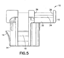
Fig. 5 is an elevational side view of the housing base shown inFig. 3 ; -
Fig. 6 is an elevational side view of the housing cover shown inFig. 4 ; -
Fig. 7 is a cross sectional view of the housing cover shown inFig. 6 taken along line 7-7; -
Fig. 8 is a perspective view of an electrical connector comprising the housing base shown inFig. 3 and the housing cover shown inFig. 4 ; -
Fig. 9 is a perspective view of an alternate embodiment of a housing base incorporating features of the invention; -
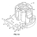
Fig. 10 is a perspective view of the housing base shown inFig. 9 from an opposite direction; -
Fig. 11 is a partial enlarged perspective view of a portion of the housing base shown inFigs. 9-10 ; -
Fig. 12 is a partial enlarged perspective view of a portion of the housing base similar toFig. 11 taken from another direction; -
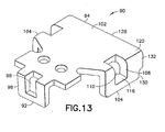
Fig. 13 is a perspective view of an alternate embodiment of a housing cover for use with the base shown inFigs. 9-12 ; -
Fig. 14 is a perspective view of the housing cover shown inFig. 13 from an opposite direction; -
Fig. 15 is a side view of the cover shown inFig. 13 ; -
Fig. 16 is a cross sectional view of the cover shown inFig. 15 taken along line 16-16; and -
Fig. 17 is a top plan view of the housing cover shown inFig. 13 . - Referring to
Figs. 3 and 4 , there are shown perspective views of an electricalconnector housing base 10 andhousing cover 12 incorporating features of the invention. Although the invention will be described with reference to the exemplary embodiments shown in the drawings, it should be understood that the invention can be embodied in many alternate forms of embodiments. In addition, any suitable size, shape or type of elements or materials could be used. - The
base 10 and cover 12 are used in conjunction with electrical contacts or terminals, and perhaps other members, such as ferrite tubes, as described inU.S. Patent No. 6,799,999 to form a Squib electrical connector, such as for use in an automobile air bag system. Thebase 10 and cover 12 are preferably each a one piece member made of molded plastic or polymer material. Referring also toFig. 5 , thebase 10 comprises afront section 14 and arear section 16. Thefront section 14 is adapted to be plugged into a socket of another member, such as an air bag initiator socket or another mating electrical connector. Thefront section 14 comprises snap-lock latches 18 for snap-lock connecting to the mating socket, twochannel holes 20 for receiving female sections of the electrical contacts, and a cover snap-lock wedge 22 at the front of the front section proximate the top of the front section. Each of the channel holes 20 (which may also be referred to as first portions of a terminal receiving area) extends in a first direction parallel to afront section 14 mating direction. - The
rear section 16 has arear side 24 with twogrooved areas 26 therethrough. Therear section 16 extends from thefront section 14 in a general cantilever fashion. The rear section has twochannel areas 28 extending from the twogrooved areas 26 to the twochannel holes 20 in thefront section 14. Aninterior wall 30 is provided separating thechannel areas 28 from each other.Lateral side walls 32 are provided at outer lateral sides of thechannel areas 28. The exterior sides of thelateral side walls 32 each comprise a snap-lock ledge 34 which extends substantially the entire length of the length of thechannel areas 28, such as more than a majority of the length. The snap-lock ledges 34 each have a generally triangular shape with a sloped or angled top side, starting at about the top of thewalls 32, and a substantially horizontal bottom side. Front and rear ends of the snap-lock ledges 34 are bounded by front andrear portions rear section 16. - The channel areas (or second portions of the terminal receiving area) 28 are adapted to receive rear connections sections of the electrical contacts therein and portions of the electrical wires. The
channel areas 28 extend in a second direction which is substantially perpendicular to the first direction of the channel holes 20. The portions of the electrical wires are attached, such as by crimping, to the rear connections sections of the electrical contacts. The electrical wires extend into thechannel areas 28 at thegrooved areas 26 between thecover 12 and thebase 10. - Referring also to
Figs. 6 and 7 , thehousing cover 12 generally comprises afront section 40 and arear section 42. Thefront section 40 generally comprises a front snap-lock section 44 with ahole 46 for snap-lock connection to the cover snap-lock wedge 22 at the top front side of thefront section 14 of thebase 10. Thefront section 40 has aportion 48 for substantially covering over the channel holes 20. Therear section 42 of thecover 12 has atop section 49, two lateral side snap-lock sections 50 extending downward from opposite lateral sides of thetop section 49, and twowire contact sections 52 extending downward from the rear side of thetop section 49. Thetop section 49 and the two lateral side snap-lock sections form a general U-shaped cross-section. - The lateral side snap-
lock sections 50 each comprise an interior facinggroove 54. When thecover 12 is attached to thebase 10, the snap-lock sections 50 are adapted to snap-lock connect to the snap-lock ledges 34 on thehousing base 10. Thegrooves 54 extend the entire length of the rear section with open front and rear ends. Thus, thegrooves 54 can receive the entire lengths of the snap-lock ledges 34 therein. This provides an increased area of latching contact (or clamping force) between thecover 12 and the base 10 than previously provided in other conventional Squib connectors. - The two
wire contact sections 52 have generally grooved bottom surfaces 56 for contacting the electrical wires. When thecover 12 is snap-lock connected to thebase 10, thesurfaces 56 and thegrooved areas 26 clamp the wires therebetween. This forms a strain relieve for the wires. Because of the increased area of latching contact between thecover 12 and the base 10 at thegrooves 54 and snap-lock ledges 34, greater clamping force can be provided on the wires by thebase 10 andcover 12. - The snap-
lock sections 50 are provided with the elongated grooves orslots 54 rather than through holes as in the prior art. The elongated grooves orslots 54 do not completely extend through the thickness of the snap-lock sections 50. Because the elongated grooves orslots 54 do not completely extend through the thickness of the snap-lock sections 50, the strength of the snap-lock sections 50 are stronger than in the prior art (lateral snap-lock connection sections having through holes therethrough). - With the invention, the housing and cover can provide an increased resistance to withstand a 90° pull force applied to the terminal wires. The invention allows improving the resistance of the connector to the increased pull force while preserving a basic conventional Squib connector design and overall size, such as a ABX-3 UC Assembly manufactured by FCI USA, Inc as shown in
Figs 1 and 2 .Fig. 8 shows a perspective view of anelectrical connector 58 comprising thecover 90,base 60, twowires 8 and twoelectrical contacts 88. - Referring now to
Figs. 9-12 perspective views of a housing base andFigs. 13-17 views of a housing cover of an alternate embodiment of a Squib air bag electrical connector is shown. Similar to the first embodiment shown inFigs. 3-8 , the second embodiment is sized and shaped to occupy the same area and shape as the conventional electrical connector shown inFig. 1 . This allows the new connectors to be used instead of theconnector 1 without having to be concerned about the surrounding available area and surrounding components which the connector will be located near, such as an automobile steering wheel housing and other components in an automobile steering wheel, or a vehicle occupant seat, or portions of a vehicle frame near the head of an occupant for example. In other words, the new connectors described herein have the same real estate and overall exterior size as theconventional connector 1. This allows a connector incorporating the invention to be used without having to redesign these surrounding components or the surrounding area. - Referring specifically to
Figs. 9 and10 , thehousing base 60 has afront section 62 and arear section 64. Thefront section 62 is identical to the front section of the housing base shown inFig. 1 . Therear section 64 generally comprises arear side 66 with twogrooved areas 68 therethrough. The rear section has twochannel areas 70 extending from the twogrooved areas 68 to the twochannel holes 20 in thefront section 62. Aninterior wall 72 is provided separating thechannel areas 70 from each other.Lateral side walls 74 are provided at outer lateral sides of thechannel areas 70. - Referring also to
Figs. 11 and12 , the exterior sides of thelateral side walls 74 each comprise a snap-lock ledge 76. The snap-lock ledges 76 each have a generally triangular shape with a sloped or angledtop side 77 and a substantially horizontalbottom side 79. Unlike the embodiment shown inFigs. 3 and5 , each snap-lock ledge 76 does not extend substantially the entire length of the rear section. Instead, each snap-lock ledge has a length about the same as the snap-lock ledge 6 used in the conventional connector shown inFig. 1 . The snap-lock ledge 76 has a substantially same size and shape as the snap-lock ledge 6 except for top side recesses 80. - The height X2 of the
side walls 74 is lower than the height X1 of the side walls of the base in theconnector 1 shown inFig. 1 . Thus, whereas the top of the snap-lock ledge 6 is even with the top of the lateral side walls in theconnector 1 ofFig. 1 , the top 82 of each snap-lock ledge 76 in the embodiment shown inFigs. 9-12 extends above thetop side 83 of thelateral side walls 74. - The
exterior side walls 74 each also comprise a snap-lock pocket 78 located beneath the bottom side of the snap-lock ledges 76. Thepockets 78 extend into theside walls 74. The rear end of thelateral side walls 74 each comprise an outward projecting finger (or lateral leg) 84. Thefinger 84 does not extend the entire height of the lateral side wall. Instead, thefingers 84 projection from a bottom portion of the lateral side walls. This is different from housing base of the conventional connector shown inFig. 1 which has a rear section that projects outward from the lateral side wall the entire height of the lateral side wall. With the reducedheight fingers 84,rear extension areas 86 are provided above thefingers 84 which can accommodateportions 132 of thecover 90 which were not provided in the prior art. Therear extension areas 86 terminate, or are flush, at therear side 66 of therear section 64. - The
channel areas 70 are adapted to receive rear connections sections of the electrical contacts therein and portions of the electrical wires. The portions of the electrical wires are attached, such as by crimping, to the rear connections sections of the electrical contacts. The electrical wires extend into thechannel areas 70 at thegrooved areas 68 between thecover 90 and thebase 60. The height of theinterior wall 72 is substantially the same as the height of the interior wall in the conventional connector shown inFig. 1 . Thus, the height of theinterior wall 72 is higher than the height of thelateral side walls 74. However, the height of therear side 66 is lower than the height of the rear side of the housing base of the conventional connector shown inFig. 1 . Thus, the height of theinterior wall 72 is higher than the height of therear side 66. - Referring now also to
Figs. 13-17 , thecover 90 comprises afront section 92 and arear section 94. Thefront section 92 is substantially the same as the front section of thehousing cover 3 of the conventional connector shown inFig. 1 . Thefront section 92 comprises a deflectable snap-lock latch section 96 with ahole 98 adapted to snap-lock connect to the snap-lock projection 100 (seeFig. 9 ) at the front of thehousing base 60. - The
rear section 94 generally comprises atop section 102, two lateral side snap-lock sections 104 extending downward from opposite lateral sides of thetop section 102, and twowire contact sections 106 extending downward from the rear side of thetop section 102. - The lateral side snap-
lock sections 104 are deflectable in a general cantilever fashion and each comprise a snap-lock latch hole 108. When thecover 90 is attached to thebase 60, the snap-lock sections 104 are adapted to snap-lock connect to the snap-lock ledges 76 on thehousing base 60. Theholes 108 extend entirely through thesections 104, but not the entire length of thesections 104. Theholes 108 are sized and shaped to receive the snap-lock ledges 76 therein. - As seen best in
Figs. 14 and16 , each lateral side snap-lock section 104 has an inward projecting snap-lock latch projection 110. Eachprojection 110 has a top generally flat horizontal side 112 (contiguous with abottom side 116 of the hole 108) and a slopedbottom side 114. The slopedsides side sections 104 during attachment of thecover 90 to thebase 60. After thecover 90 is attached to thebase 60, theside sections 104 resiliently deflect back to their home positions to locate thesurfaces lock pocket 78 provides an area for the snap-lock latch projection 110 to extend into. - Referring also to
Fig. 16 ,area 112 combines witharea 116 at the bottom of thehole 108 to form an enlarge area of contact between the cover and the base. Thewidth 118 of eachsections 104 is larger than the width of the lateral side snap-lock sections in the conventionalelectrical connector cover 3 shown inFig. 1 . Thus, the size of thearea 116 is larger than the equivalent area in the conventionalelectrical connector cover 3 shown inFig. 1 . The increasedsize area 116 andarea 112 combine to create an even larger area than in the prior art. In the prior art, the size of the area was merely the thickness of the smaller width lateral side snap-lock section at thehole 4. With the combined increasedsize area 116 andarea 112, this increases resistance to pull-off of thecover 90 from thebase 60. - The thicknesses of the
walls 74 are reduced to accommodate the increasedthicknesses 118 of thesections 104. This keeps the outer dimensions of the overall housing the same as the prior art. In an alternate embodiment, thewidth 118 could be the same as the prior art with merely surfaces 112 adding the additional area. -
Portion 126 of thetop section 102 proximate the bend (or bend section) 120 of the connection of thelateral side sections 104 to thetop section 102 has an increasedthickness 122 versus the conventionalelectrical connector cover 3 shown inFig. 1 . However, thethickness 124 of the top section 102 (except atportion 126 and its rear end) remains the same as the conventionalelectrical connector cover 3 shown inFig. 1 . Thebend 120 has an increased thickness as it transitions fromportion 126 to thesection 104. The increased thicknesses increase the strength of thebend 120 versus the prior art. This makes it more difficult for thecover 90 to be inadvertently disconnected from the base 60 by pulling action on the electrical wires such as in direction 9 shown inFig. 1 . - The rear section of the
cover 90 has arear end 128. Therear end 128 hasbottom notches 130. Eachnotch 130 is sized and shaped to receive one of thefingers 84 of the base 60 therein. Unlike the conventionalelectrical connector cover 3 shown inFig. 1 , thelateral side sections 104 extend to the rear end of the connector; except at thenotches 130. Thus, thelateral side sections 104 haverear extension portions 132 located above thenotches 130 which were not provided in theconventional cover 3. These additionalrear extension portions 132 increase the strength of the deflectable bend between thetop section 102 and thelateral side sections 104. This makes it more difficult for thecover 90 to be inadvertently disconnected from the base 60 by pulling action on the electrical wires. - The two
wire contact sections 106 have generally grooved bottom surfaces 134 for contacting the electrical wires. When thecover 90 is snap-lock connected to thebase 60, thesurfaces 134 and thegrooved areas 68 clamp the wires therebetween. This forms a strain relieve for the wires. Because of the increased area of latching contact between thecover 90 and thebase 60, greater clamping force can be provided on the wires by thebase 60 andcover 90. - With the embodiment shown in
Figs. 9-17 , even though thesizes cover 90 have been increased, reductions in the corresponding areas of the base 60 have been made to maintain the overall exterior dimensions of the housing to be the same as the housing of the conventional connector shown inFig. 1 . The increasedsizes cover 90 from the base 60 by a pull force on the wires. In addition, the addition of theportions 132 and snap-lock projections 110 (withpockets 78 in the base 60) provide an even greater pull-off resistance of thecover 90 from the base 60 by a pull force on the wires, such as direction 9 shown inFig. 1 . In alternate embodiments, more or less than all of these pull-off resistance features could be provided. With the embodiments described above, the overall length L, width W and height H of the rear section of theprior art connector 1 shown inFig. 1 is the same as the length, width and height of the connectors shown inFigs. 3-17 . However, the connector housings shown inFigs. 3-17 have an increased resistance to pull-off of the housing cover from the housing base versus the prior art connector shown inFig. 1 . - It should be understood that the foregoing description is only illustrative of the invention. Various alternatives and modifications can be devised by those skilled in the art without departing from the invention. Accordingly, the present invention is intended to embrace all such alternatives, modifications and variances which fall within the scope of the appended claims.
Claims (16)
- An electrical connector comprising:a base (10) comprising a front section (14) and a rear section (16), wherein the base (10) comprises at least one terminal receiving area, wherein the front section (14) comprises a first portion of the terminal receiving area (20) extending in a first direction, wherein the rear section (16) comprises a first snap-lock ledge (34) and a second portion of the terminal receiving area extending in a second direction, wherein the rear section comprises a rear side (24) having two grooved areas (26) therethrough, and wherein the second portion extends from the two grooved areas to the first portion of the terminal receiving area, and wherein the rear section extends from the front section (14) to the rear side (24),a cover (12) comprising a top section (49) and a first lateral side section (50) extending from the top section (49), wherein the first lateral side section receives the first snap-lock ledge (34), andan electrical terminal mounted between the base (10) and the cover (12),characterized in that the first snap-lock ledge (34) extends along a majority of a length of the rear section substantially the entire length of a length of the second portion of the terminal receiving area (28), wherein the first lateral side section (50) of the cover (12) further comprises a groove (54), wherein the first snap-lock ledge (34) is disposed within the groove.
- The electrical connector of claim 1 wherein the rear section further comprises a front portion and a rear portion, and wherein the first snap-lock ledge (34) extends from the front portion to the rear portion.
- The electrical connector of claim 1 wherein the rear section further comprises a second snap-lock ledge (34) opposite the first snap-lock ledge (34), and wherein the second snap-lock ledge extends substantially the entire length of the length of the second portion of the terminal receiving area.
- The electrical connector of claim 3 wherein the cover (10) further comprises a second lateral side (50)section extending from the top section (49), wherein the second lateral side section receives the second snap-lock ledge (34).
- The electrical connector of claim 1 wherein the groove (54) comprises open opposite ends along a length of the first lateral side section (50).
- An electrical connector housing comprising:a housing base (10) comprising a front section and a rear section, wherein the front section comprises a first portion of a terminal receiving area, wherein the rear section extends from the front section in a general cantilever fashion, and wherein the rear section comprises a second portion of the terminal receiving area, the rear section comprises a rear side (24) having two grooved areas (26) therethrough, and wherein the second portion extends from the two grooved areas to the first portion of the terminal receiving area anda housing cover (12) having a rear section with a general U-shaped cross-section attached to the housing base (10), wherein the housing cover (12) comprises opposing lateral side sections (50), wherein each of the opposing lateral side sections (50) comprises a snap-lock groove (54),characterized in that the snap-lock grooves (54) extend substantially the entire length of a length of the second portion of the terminal receiving area, wherein the rear section of the housing base (10) comprises opposing snap-lock ledges (34) disposed within the snap-lock grooves (54).
- The electrical connector housing of claim 6 wherein the snap-lock grooves (54) comprise open opposite ends along a length of each of the lateral side sections (50).
- The electrical connector housing of claim 6 wherein the rear section of the housing base (10) further comprises channel areas (28) extending between the front section and a rear side of the rear section, and wherein the snap-lock ledges (34) extend substantially the entire length of the length of the second portion of the terminal receiving area.
- The electrical connector housing of claim 6 wherein the rear section of the housing base (10) further comprises a front portion and a rear portion, and wherein each of the snap-lock ledges (34) extend from the front portion to the rear portion.
- The electrical connector housing of claim 6 wherein the housing cover (12) further comprises grooved surfaces extending from a top section of the housing cover, wherein the grooved surfaces are configured to provide a clamping force to the terminal in response to the clamping force substantially along the entire length of the length of the second portion of the terminal receiving area.
- An electrical connector comprising:a base (10) comprising a front section and a rear section, wherein the base (10) comprises at least one terminal receiving area, wherein the front section comprises a first portion of the terminal receiving area (28)extending in a first direction, wherein the rear section comprises a second portion of the terminal receiving area extending in a second direction,a cover (12) connected to the base (10), wherein the cover (10) comprises a top section, opposing lateral side sections (50), and bend sections connecting the lateral side sections to the top section, wherein the lateral side sections (50) comprise a snap-lock hole (20), and wherein the bend sections extend from the snap-lock hole (20) to a rear side of the base (10), andan electrical terminal mounted between the base (10) and the cover (12)characterized in that the rear section comprises side walls disposed laterally outward from the second portion of the terminal receiving area (28) and lateral legs (84) extending from bottom portions of the side walls adjacent the rear side, wherein each of the side walls further comprise a top side and a snap-lock ledge (76),wherein a top of the snap-lock ledge (76) extends above the top side of the side wall.
- The electrical connector of claim 11 wherein the side walls further comprise a rear extension area (86) above the lateral legs (84).
- The electrical connector of claim 11 wherein each of the lateral side sections (50) of the cover (12) further comprise a notch, wherein the notch receives the lateral leg (84).
- The electrical connector of claim 12 wherein each of the lateral side sections of the cover (12) further comprise a rear extension portion, wherein the rear extension area (86) is configured to accommodate the rear extension portion (132).
- The electrical connector of claim 14 wherein each of the rear extension portions (132) extend from the lateral side sections (50) and terminate at the rear side of the base (10).
- The electrical connector of claim 11 wherein a thickness of the lateral side sections (50) and a thickness of the bend sections of the cover (12) are each greater than a thickness of the top section of the cover.
Applications Claiming Priority (3)
| Application Number | Priority Date | Filing Date | Title |
|---|---|---|---|
| US76404806P | 2006-01-31 | 2006-01-31 | |
| US11/622,022 US7344403B2 (en) | 2006-01-31 | 2007-01-11 | Squib connector with improved cover connection |
| PCT/US2007/002483 WO2007123590A2 (en) | 2006-01-31 | 2007-01-29 | Squib connector with improved cover connection |
Publications (3)
| Publication Number | Publication Date |
|---|---|
| EP1984986A2 EP1984986A2 (en) | 2008-10-29 |
| EP1984986A4 EP1984986A4 (en) | 2012-04-25 |
| EP1984986B1 true EP1984986B1 (en) | 2015-11-11 |
Family
ID=38322652
Family Applications (1)
| Application Number | Title | Priority Date | Filing Date |
|---|---|---|---|
| EP07794317.3A Not-in-force EP1984986B1 (en) | 2006-01-31 | 2007-01-29 | Squib connector with improved cover connection |
Country Status (5)
| Country | Link |
|---|---|
| US (1) | US7344403B2 (en) |
| EP (1) | EP1984986B1 (en) |
| JP (1) | JP4938800B2 (en) |
| CN (1) | CN101379664B (en) |
| WO (1) | WO2007123590A2 (en) |
Families Citing this family (8)
| Publication number | Priority date | Publication date | Assignee | Title |
|---|---|---|---|---|
| US7892025B2 (en) * | 2008-07-18 | 2011-02-22 | Tyco Electronics Corporation | Sealed connector assembly |
| IN2014CN03639A (en) * | 2011-10-20 | 2015-07-03 | Delphi Int Operations Lux Srl | |
| JP6279846B2 (en) * | 2013-07-01 | 2018-02-14 | 日本圧着端子製造株式会社 | Electrical connector and squib connection device |
| CN203660180U (en) * | 2013-12-06 | 2014-06-18 | 友达光电股份有限公司 | Connector fixture and connector module applying the connector fixture |
| DK3292595T3 (en) | 2015-05-06 | 2025-06-02 | Lego As | ELECTRICAL CONNECTOR AND CONNECTOR ELEMENTS FOR A MODULAR CONSTRUCTION ELEMENT AND/OR SYSTEM |
| US10488231B2 (en) * | 2016-08-18 | 2019-11-26 | Ford Global Technologies, Llc | Sensor cover |
| EP3396790A1 (en) * | 2017-04-27 | 2018-10-31 | Delphi International Operations Luxembourg S.à r.l. | Connector assembly for safety systems |
| CN210326329U (en) * | 2019-06-21 | 2020-04-14 | 重庆市鸿腾科技有限公司 | Socket connector and plug connector connected with same |
Family Cites Families (8)
| Publication number | Priority date | Publication date | Assignee | Title |
|---|---|---|---|---|
| JP3247932B2 (en) * | 1996-12-27 | 2002-01-21 | タイコエレクトロニクスアンプ株式会社 | Ignition tube connector |
| US6250952B1 (en) * | 1997-08-08 | 2001-06-26 | The Whitaker Corporation | Air bag connector |
| KR100564091B1 (en) * | 2000-03-01 | 2006-03-27 | 니혼 앗사쿠단시세이조 가부시키가이샤 | Electrical connection system |
| JP4937461B2 (en) * | 2000-04-25 | 2012-05-23 | トーマス・アンド・ベッツ・インターナショナル・インコーポレーテッド | Plug connector |
| JP3607883B2 (en) * | 2001-06-22 | 2005-01-05 | 日本圧着端子製造株式会社 | Electrical connection device with latch |
| JP2003249308A (en) * | 2002-02-25 | 2003-09-05 | Tyco Electronics Amp Kk | Electrical connector assembly |
| US6799999B2 (en) * | 2003-02-07 | 2004-10-05 | Fci Americas Technology, Inc. | Filtered electrical connector |
| JP2005116395A (en) * | 2003-10-09 | 2005-04-28 | Jst Mfg Co Ltd | Electrical connection device |
-
2007
- 2007-01-11 US US11/622,022 patent/US7344403B2/en not_active Expired - Fee Related
- 2007-01-29 JP JP2008553299A patent/JP4938800B2/en not_active Expired - Fee Related
- 2007-01-29 CN CN2007800039870A patent/CN101379664B/en not_active Expired - Fee Related
- 2007-01-29 WO PCT/US2007/002483 patent/WO2007123590A2/en not_active Ceased
- 2007-01-29 EP EP07794317.3A patent/EP1984986B1/en not_active Not-in-force
Also Published As
| Publication number | Publication date |
|---|---|
| JP4938800B2 (en) | 2012-05-23 |
| EP1984986A2 (en) | 2008-10-29 |
| CN101379664B (en) | 2012-01-04 |
| US20070178730A1 (en) | 2007-08-02 |
| WO2007123590A2 (en) | 2007-11-01 |
| WO2007123590A3 (en) | 2008-03-06 |
| US7344403B2 (en) | 2008-03-18 |
| JP2009525586A (en) | 2009-07-09 |
| CN101379664A (en) | 2009-03-04 |
| EP1984986A4 (en) | 2012-04-25 |
Similar Documents
| Publication | Publication Date | Title |
|---|---|---|
| US8333622B2 (en) | Dual contact beam terminal | |
| US7344403B2 (en) | Squib connector with improved cover connection | |
| US6524143B2 (en) | Female crimp terminal | |
| US8795007B2 (en) | Terminal fitting | |
| EP1635425B1 (en) | Connection terminal | |
| US6482035B2 (en) | Press-connecting connector | |
| JP2007524193A (en) | Female terminal with flexible side wall and flat inclined contact | |
| KR102249929B1 (en) | Electrical terminals and connector assemblies | |
| EP1548894B1 (en) | A connector | |
| US7775837B2 (en) | Electrical connector with improved clip member | |
| JP2004362973A (en) | Terminal fitting | |
| JP5700811B2 (en) | connector | |
| JP2007165307A (en) | Electrical connector | |
| KR101442297B1 (en) | Low profile shorting bar for electrical connectors | |
| EP1601061B1 (en) | A terminal and a method of forming it | |
| KR20130067308A (en) | Electrical plug connector having an upstream contact terminal | |
| US20060199418A1 (en) | Electrical connector assembly | |
| JP7144290B2 (en) | Terminal connection structure | |
| JP2012028084A (en) | Connector | |
| JP3599175B2 (en) | Terminal fitting | |
| JP2005038761A (en) | Female terminal | |
| JP2003157925A (en) | Terminal fittings | |
| JP2013109835A (en) | Female terminal for flat cable | |
| KR200464159Y1 (en) | Tab terminal and terminal assembly having this | |
| CN119866579A (en) | Connector with a plurality of connectors |
Legal Events
| Date | Code | Title | Description |
|---|---|---|---|
| PUAI | Public reference made under article 153(3) epc to a published international application that has entered the european phase |
Free format text: ORIGINAL CODE: 0009012 |
|
| 17P | Request for examination filed |
Effective date: 20080825 |
|
| AK | Designated contracting states |
Kind code of ref document: A2 Designated state(s): AT BE BG CH CY CZ DE DK EE ES FI FR GB GR HU IE IS IT LI LT LU LV MC NL PL PT RO SE SI SK TR |
|
| RAP1 | Party data changed (applicant data changed or rights of an application transferred) |
Owner name: FCI |
|
| RAP1 | Party data changed (applicant data changed or rights of an application transferred) |
Owner name: FCI AUTOMOTIVE HOLDING |
|
| A4 | Supplementary search report drawn up and despatched |
Effective date: 20120328 |
|
| RIC1 | Information provided on ipc code assigned before grant |
Ipc: H01R 13/627 20060101AFI20120322BHEP Ipc: H01R 13/506 20060101ALI20120322BHEP |
|
| 17Q | First examination report despatched |
Effective date: 20120417 |
|
| DAX | Request for extension of the european patent (deleted) | ||
| RAP1 | Party data changed (applicant data changed or rights of an application transferred) |
Owner name: DELPHI INTERNATIONAL OPERATIONS LUXEMBOURG S.A R.L |
|
| GRAP | Despatch of communication of intention to grant a patent |
Free format text: ORIGINAL CODE: EPIDOSNIGR1 |
|
| INTG | Intention to grant announced |
Effective date: 20150617 |
|
| GRAS | Grant fee paid |
Free format text: ORIGINAL CODE: EPIDOSNIGR3 |
|
| GRAA | (expected) grant |
Free format text: ORIGINAL CODE: 0009210 |
|
| AK | Designated contracting states |
Kind code of ref document: B1 Designated state(s): AT BE BG CH CY CZ DE DK EE ES FI FR GB GR HU IE IS IT LI LT LU LV MC NL PL PT RO SE SI SK TR |
|
| REG | Reference to a national code |
Ref country code: GB Ref legal event code: FG4D |
|
| REG | Reference to a national code |
Ref country code: CH Ref legal event code: EP |
|
| REG | Reference to a national code |
Ref country code: IE Ref legal event code: FG4D |
|
| REG | Reference to a national code |
Ref country code: AT Ref legal event code: REF Ref document number: 760871 Country of ref document: AT Kind code of ref document: T Effective date: 20151215 |
|
| REG | Reference to a national code |
Ref country code: DE Ref legal event code: R096 Ref document number: 602007043878 Country of ref document: DE |
|
| REG | Reference to a national code |
Ref country code: FR Ref legal event code: PLFP Year of fee payment: 10 |
|
| REG | Reference to a national code |
Ref country code: LT Ref legal event code: MG4D |
|
| REG | Reference to a national code |
Ref country code: NL Ref legal event code: MP Effective date: 20160211 |
|
| REG | Reference to a national code |
Ref country code: AT Ref legal event code: MK05 Ref document number: 760871 Country of ref document: AT Kind code of ref document: T Effective date: 20151111 |
|
| PG25 | Lapsed in a contracting state [announced via postgrant information from national office to epo] |
Ref country code: IS Free format text: LAPSE BECAUSE OF FAILURE TO SUBMIT A TRANSLATION OF THE DESCRIPTION OR TO PAY THE FEE WITHIN THE PRESCRIBED TIME-LIMIT Effective date: 20160311 Ref country code: NL Free format text: LAPSE BECAUSE OF FAILURE TO SUBMIT A TRANSLATION OF THE DESCRIPTION OR TO PAY THE FEE WITHIN THE PRESCRIBED TIME-LIMIT Effective date: 20151111 Ref country code: LT Free format text: LAPSE BECAUSE OF FAILURE TO SUBMIT A TRANSLATION OF THE DESCRIPTION OR TO PAY THE FEE WITHIN THE PRESCRIBED TIME-LIMIT Effective date: 20151111 Ref country code: ES Free format text: LAPSE BECAUSE OF FAILURE TO SUBMIT A TRANSLATION OF THE DESCRIPTION OR TO PAY THE FEE WITHIN THE PRESCRIBED TIME-LIMIT Effective date: 20151111 |
|
| PG25 | Lapsed in a contracting state [announced via postgrant information from national office to epo] |
Ref country code: FI Free format text: LAPSE BECAUSE OF FAILURE TO SUBMIT A TRANSLATION OF THE DESCRIPTION OR TO PAY THE FEE WITHIN THE PRESCRIBED TIME-LIMIT Effective date: 20151111 Ref country code: SE Free format text: LAPSE BECAUSE OF FAILURE TO SUBMIT A TRANSLATION OF THE DESCRIPTION OR TO PAY THE FEE WITHIN THE PRESCRIBED TIME-LIMIT Effective date: 20151111 Ref country code: PT Free format text: LAPSE BECAUSE OF FAILURE TO SUBMIT A TRANSLATION OF THE DESCRIPTION OR TO PAY THE FEE WITHIN THE PRESCRIBED TIME-LIMIT Effective date: 20160311 Ref country code: AT Free format text: LAPSE BECAUSE OF FAILURE TO SUBMIT A TRANSLATION OF THE DESCRIPTION OR TO PAY THE FEE WITHIN THE PRESCRIBED TIME-LIMIT Effective date: 20151111 Ref country code: PL Free format text: LAPSE BECAUSE OF FAILURE TO SUBMIT A TRANSLATION OF THE DESCRIPTION OR TO PAY THE FEE WITHIN THE PRESCRIBED TIME-LIMIT Effective date: 20151111 Ref country code: GR Free format text: LAPSE BECAUSE OF FAILURE TO SUBMIT A TRANSLATION OF THE DESCRIPTION OR TO PAY THE FEE WITHIN THE PRESCRIBED TIME-LIMIT Effective date: 20160212 Ref country code: BE Free format text: LAPSE BECAUSE OF NON-PAYMENT OF DUE FEES Effective date: 20160131 Ref country code: LV Free format text: LAPSE BECAUSE OF FAILURE TO SUBMIT A TRANSLATION OF THE DESCRIPTION OR TO PAY THE FEE WITHIN THE PRESCRIBED TIME-LIMIT Effective date: 20151111 |
|
| PG25 | Lapsed in a contracting state [announced via postgrant information from national office to epo] |
Ref country code: CZ Free format text: LAPSE BECAUSE OF FAILURE TO SUBMIT A TRANSLATION OF THE DESCRIPTION OR TO PAY THE FEE WITHIN THE PRESCRIBED TIME-LIMIT Effective date: 20151111 |
|
| REG | Reference to a national code |
Ref country code: DE Ref legal event code: R097 Ref document number: 602007043878 Country of ref document: DE |
|
| PG25 | Lapsed in a contracting state [announced via postgrant information from national office to epo] |
Ref country code: SK Free format text: LAPSE BECAUSE OF FAILURE TO SUBMIT A TRANSLATION OF THE DESCRIPTION OR TO PAY THE FEE WITHIN THE PRESCRIBED TIME-LIMIT Effective date: 20151111 Ref country code: LU Free format text: LAPSE BECAUSE OF FAILURE TO SUBMIT A TRANSLATION OF THE DESCRIPTION OR TO PAY THE FEE WITHIN THE PRESCRIBED TIME-LIMIT Effective date: 20160129 Ref country code: EE Free format text: LAPSE BECAUSE OF FAILURE TO SUBMIT A TRANSLATION OF THE DESCRIPTION OR TO PAY THE FEE WITHIN THE PRESCRIBED TIME-LIMIT Effective date: 20151111 Ref country code: RO Free format text: LAPSE BECAUSE OF FAILURE TO SUBMIT A TRANSLATION OF THE DESCRIPTION OR TO PAY THE FEE WITHIN THE PRESCRIBED TIME-LIMIT Effective date: 20151111 Ref country code: DK Free format text: LAPSE BECAUSE OF FAILURE TO SUBMIT A TRANSLATION OF THE DESCRIPTION OR TO PAY THE FEE WITHIN THE PRESCRIBED TIME-LIMIT Effective date: 20151111 |
|
| REG | Reference to a national code |
Ref country code: CH Ref legal event code: PL |
|
| PLBE | No opposition filed within time limit |
Free format text: ORIGINAL CODE: 0009261 |
|
| STAA | Information on the status of an ep patent application or granted ep patent |
Free format text: STATUS: NO OPPOSITION FILED WITHIN TIME LIMIT |
|
| PG25 | Lapsed in a contracting state [announced via postgrant information from national office to epo] |
Ref country code: MC Free format text: LAPSE BECAUSE OF FAILURE TO SUBMIT A TRANSLATION OF THE DESCRIPTION OR TO PAY THE FEE WITHIN THE PRESCRIBED TIME-LIMIT Effective date: 20151111 |
|
| 26N | No opposition filed |
Effective date: 20160812 |
|
| PG25 | Lapsed in a contracting state [announced via postgrant information from national office to epo] |
Ref country code: CH Free format text: LAPSE BECAUSE OF NON-PAYMENT OF DUE FEES Effective date: 20160131 Ref country code: LI Free format text: LAPSE BECAUSE OF NON-PAYMENT OF DUE FEES Effective date: 20160131 |
|
| REG | Reference to a national code |
Ref country code: IE Ref legal event code: MM4A |
|
| PG25 | Lapsed in a contracting state [announced via postgrant information from national office to epo] |
Ref country code: SI Free format text: LAPSE BECAUSE OF FAILURE TO SUBMIT A TRANSLATION OF THE DESCRIPTION OR TO PAY THE FEE WITHIN THE PRESCRIBED TIME-LIMIT Effective date: 20151111 |
|
| PG25 | Lapsed in a contracting state [announced via postgrant information from national office to epo] |
Ref country code: BE Free format text: LAPSE BECAUSE OF FAILURE TO SUBMIT A TRANSLATION OF THE DESCRIPTION OR TO PAY THE FEE WITHIN THE PRESCRIBED TIME-LIMIT Effective date: 20151111 |
|
| REG | Reference to a national code |
Ref country code: FR Ref legal event code: PLFP Year of fee payment: 11 |
|
| PG25 | Lapsed in a contracting state [announced via postgrant information from national office to epo] |
Ref country code: IE Free format text: LAPSE BECAUSE OF NON-PAYMENT OF DUE FEES Effective date: 20160129 |
|
| REG | Reference to a national code |
Ref country code: FR Ref legal event code: PLFP Year of fee payment: 12 |
|
| PG25 | Lapsed in a contracting state [announced via postgrant information from national office to epo] |
Ref country code: CY Free format text: LAPSE BECAUSE OF FAILURE TO SUBMIT A TRANSLATION OF THE DESCRIPTION OR TO PAY THE FEE WITHIN THE PRESCRIBED TIME-LIMIT Effective date: 20151111 Ref country code: HU Free format text: LAPSE BECAUSE OF FAILURE TO SUBMIT A TRANSLATION OF THE DESCRIPTION OR TO PAY THE FEE WITHIN THE PRESCRIBED TIME-LIMIT; INVALID AB INITIO Effective date: 20070129 |
|
| PG25 | Lapsed in a contracting state [announced via postgrant information from national office to epo] |
Ref country code: TR Free format text: LAPSE BECAUSE OF FAILURE TO SUBMIT A TRANSLATION OF THE DESCRIPTION OR TO PAY THE FEE WITHIN THE PRESCRIBED TIME-LIMIT Effective date: 20151111 |
|
| PG25 | Lapsed in a contracting state [announced via postgrant information from national office to epo] |
Ref country code: BG Free format text: LAPSE BECAUSE OF FAILURE TO SUBMIT A TRANSLATION OF THE DESCRIPTION OR TO PAY THE FEE WITHIN THE PRESCRIBED TIME-LIMIT Effective date: 20151111 |
|
| REG | Reference to a national code |
Ref country code: DE Ref legal event code: R081 Ref document number: 602007043878 Country of ref document: DE Owner name: APTIV TECHNOLOGIES LIMITED, BB Free format text: FORMER OWNER: DELPHI INTERNATIONAL OPERATIONS LUXEMBOURG S.A R.L., BASCHARAGE, LU |
|
| REG | Reference to a national code |
Ref country code: GB Ref legal event code: 732E Free format text: REGISTERED BETWEEN 20181213 AND 20181219 |
|
| PGFP | Annual fee paid to national office [announced via postgrant information from national office to epo] |
Ref country code: DE Payment date: 20190129 Year of fee payment: 13 Ref country code: IT Payment date: 20190123 Year of fee payment: 13 Ref country code: GB Payment date: 20190128 Year of fee payment: 13 Ref country code: FR Payment date: 20190125 Year of fee payment: 13 |
|
| REG | Reference to a national code |
Ref country code: DE Ref legal event code: R119 Ref document number: 602007043878 Country of ref document: DE |
|
| GBPC | Gb: european patent ceased through non-payment of renewal fee |
Effective date: 20200129 |
|
| PG25 | Lapsed in a contracting state [announced via postgrant information from national office to epo] |
Ref country code: DE Free format text: LAPSE BECAUSE OF NON-PAYMENT OF DUE FEES Effective date: 20200801 Ref country code: FR Free format text: LAPSE BECAUSE OF NON-PAYMENT OF DUE FEES Effective date: 20200131 Ref country code: GB Free format text: LAPSE BECAUSE OF NON-PAYMENT OF DUE FEES Effective date: 20200129 |
|
| PG25 | Lapsed in a contracting state [announced via postgrant information from national office to epo] |
Ref country code: IT Free format text: LAPSE BECAUSE OF NON-PAYMENT OF DUE FEES Effective date: 20200129 |
|
| P01 | Opt-out of the competence of the unified patent court (upc) registered |
Effective date: 20230425 |