EP1984264B1 - Drawer-and-shell type package - Google Patents
Drawer-and-shell type package Download PDFInfo
- Publication number
- EP1984264B1 EP1984264B1 EP07704998.9A EP07704998A EP1984264B1 EP 1984264 B1 EP1984264 B1 EP 1984264B1 EP 07704998 A EP07704998 A EP 07704998A EP 1984264 B1 EP1984264 B1 EP 1984264B1
- Authority
- EP
- European Patent Office
- Prior art keywords
- tab
- package
- belt
- tab members
- sleeve
- Prior art date
- Legal status (The legal status is an assumption and is not a legal conclusion. Google has not performed a legal analysis and makes no representation as to the accuracy of the status listed.)
- Active
Links
Images


Classifications
-
- B—PERFORMING OPERATIONS; TRANSPORTING
- B65—CONVEYING; PACKING; STORING; HANDLING THIN OR FILAMENTARY MATERIAL
- B65D—CONTAINERS FOR STORAGE OR TRANSPORT OF ARTICLES OR MATERIALS, e.g. BAGS, BARRELS, BOTTLES, BOXES, CANS, CARTONS, CRATES, DRUMS, JARS, TANKS, HOPPERS, FORWARDING CONTAINERS; ACCESSORIES, CLOSURES, OR FITTINGS THEREFOR; PACKAGING ELEMENTS; PACKAGES
- B65D5/00—Rigid or semi-rigid containers of polygonal cross-section, e.g. boxes, cartons or trays, formed by folding or erecting one or more blanks made of paper
- B65D5/38—Drawer-and-shell type containers
-
- B—PERFORMING OPERATIONS; TRANSPORTING
- B65—CONVEYING; PACKING; STORING; HANDLING THIN OR FILAMENTARY MATERIAL
- B65D—CONTAINERS FOR STORAGE OR TRANSPORT OF ARTICLES OR MATERIALS, e.g. BAGS, BARRELS, BOTTLES, BOXES, CANS, CARTONS, CRATES, DRUMS, JARS, TANKS, HOPPERS, FORWARDING CONTAINERS; ACCESSORIES, CLOSURES, OR FITTINGS THEREFOR; PACKAGING ELEMENTS; PACKAGES
- B65D5/00—Rigid or semi-rigid containers of polygonal cross-section, e.g. boxes, cartons or trays, formed by folding or erecting one or more blanks made of paper
- B65D5/42—Details of containers or of foldable or erectable container blanks
- B65D5/44—Integral, inserted or attached portions forming internal or external fittings
- B65D5/52—External stands or display elements for contents
- B65D5/5213—Internal elements supporting the contents and movable for displaying them, e.g. movable bottoms or trays
-
- B—PERFORMING OPERATIONS; TRANSPORTING
- B65—CONVEYING; PACKING; STORING; HANDLING THIN OR FILAMENTARY MATERIAL
- B65D—CONTAINERS FOR STORAGE OR TRANSPORT OF ARTICLES OR MATERIALS, e.g. BAGS, BARRELS, BOTTLES, BOXES, CANS, CARTONS, CRATES, DRUMS, JARS, TANKS, HOPPERS, FORWARDING CONTAINERS; ACCESSORIES, CLOSURES, OR FITTINGS THEREFOR; PACKAGING ELEMENTS; PACKAGES
- B65D85/00—Containers, packaging elements or packages, specially adapted for particular articles or materials
- B65D85/07—Containers, packaging elements or packages, specially adapted for particular articles or materials for compressible or flexible articles
- B65D85/08—Containers, packaging elements or packages, specially adapted for particular articles or materials for compressible or flexible articles rod-shaped or tubular
- B65D85/10—Containers, packaging elements or packages, specially adapted for particular articles or materials for compressible or flexible articles rod-shaped or tubular for cigarettes
-
- B—PERFORMING OPERATIONS; TRANSPORTING
- B65—CONVEYING; PACKING; STORING; HANDLING THIN OR FILAMENTARY MATERIAL
- B65D—CONTAINERS FOR STORAGE OR TRANSPORT OF ARTICLES OR MATERIALS, e.g. BAGS, BARRELS, BOTTLES, BOXES, CANS, CARTONS, CRATES, DRUMS, JARS, TANKS, HOPPERS, FORWARDING CONTAINERS; ACCESSORIES, CLOSURES, OR FITTINGS THEREFOR; PACKAGING ELEMENTS; PACKAGES
- B65D85/00—Containers, packaging elements or packages, specially adapted for particular articles or materials
- B65D85/54—Containers, packaging elements or packages, specially adapted for particular articles or materials for articles of special shape not otherwise provided for
- B65D85/544—Containers, packaging elements or packages, specially adapted for particular articles or materials for articles of special shape not otherwise provided for for gramophone records
Definitions
- the package comprises a sleeve having opposed open ends, wherein at least one of the tab members is wholly or substantially within the sleeve when in the closed position and can protrude from the sleeve through one or other of the open ends when moved in either of the first and second directions.
- the or each tab member may be shorter than or equal to the length of the sleeve.
- one or both of the tab members may include extended portions which protrude from the sleeve when said tab member is in the closed position, thereby enabling a user easily to grasp and pull the extended portion to open the package.
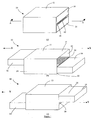
- the box 10 includes a hollow rectangular body or sleeve 12 defining a through passage for housing a first tab member 14 and a second tab member 16.
- the sleeve 12 has an upper wall 18, a lower wall 20, two side walls 22, 24 and two open ends 26, 28.
- the box 10 also includes a planar divider 30 extending across the passage, between the open ends 26, 28 of the sleeve 12, and dividing the passage into upper and lower passages.
- the tab members 14, 16 extend the length of the through passage and, in this embodiment, are dimensioned so that they can be accommodated wholly within the sleeve 12.
- the first tab member 14 is housed in the lower passage, and the second tab member 16 is housed in the upper passage.
- the tab members 14, 16 are movable back and forth, relative to the divider 30 and the sleeve 12, towards and away from one another.
- FIG. 6 A further embodiment of the invention is shown in Figure 6 , in which the bonds 45, 46 are offset from one another, but are not equidistant from the plane Z.
- movement of the first tab member 14 in the direction of arrow X, and movement of the second tab member 16 in the direction of arrow Y, is delimited by the second bond 46 reaching an end 37 of the belt path, despite the first bond 45 not reaching the other end 39 of the belt path.
- the box 10 is in the first fully open position, whereby the tab members 14, 16 project from the sleeve 12 to a first maximum extent as indicated by the double-headed arrows 47.
Description
- The present invention relates to packaging, such as a box, which may be used in the packaging of any item. Examples are the packaging of pharmaceutical products, mobile telephones, mp3 players, portable computer games consoles, compact discs, digital video discs, chocolates, cosmetics, cigarettes, swatch samples and information cards.
- Pharmaceutical products such as tablets and capsules are often packaged in blister packs. Blister packs comprise a moulded plastic base having raised areas or blisters for containing the tablets or capsules, and the base is covered by foil. Blister packs are usually packaged in a box together with a leaflet containing information about the medication.
- Packaging is important when marketing a product as good packaging may result in increased sales of the product. Good packaging should hold items securely, but also be easy and convenient to open by people of all levels of ability and dexterity. In addition to these functional attributes, good packaging should also have an attractive appearance and, preferably, intriguing characteristics.
-
EP1140639 of the Applicant, the subject matter of which is incorporated into this specification by reference, describes a box comprising a generally tubular sleeve defining a through passage, a planar divider extending across said passage, a belt extending around said divider, and a tray member extending into said passage, characterised in that the box further comprises a tab member extending into said passage, and wherein each of said tray member and said tab member are attached to said belt, such that when said tab member is moved out of said passage in a first direction said tray member moves out of said passage in a second direction opposite to said first direction, and said belt is in the form of a continuous loop such that when said tab member is moved into said passage in said second direction said tray member moves into said passage in said first direction. - The box of
EP1140639 is appealing as a user is surprised, upon first opening the box, that the tray moves automatically in the opposite direction when the tab member is pulled. - The Applicant has also devised an improved box or package, which is described in UK patent application
GB 0519581.3 GB 2428236 -
GB 0519581.3 - It is an object of the invention to provide improved packaging, which is even more interesting, attractive and/or surprising than the prior art.
- The invention provides a package comprising a belt extending between a first end and a second end of a belt path; and first and second tab members attached to the belt such that when the first tab member is moved in a first direction, the second tab member is driven by the belt to move in a second direction different to the first direction; wherein the tab members are attached to the belt by respective bonds, the movement of the tab members in either direction being delimited by at least one bond reaching an end of the belt path; and when at least one of the tab members is in a closed position, said bond is positioned inwardly from the ends of the belt path so that said tab member can move in both the first and second directions from the closed position before the bond reaches an end of the belt path to delimit said movement.
- The package is particularly suitable for packaging pharmaceutical products, although the invention is not limited to such applications. For example, one or both tab members may comprise a blister pack containing tablets or capsules. The blister pack may be attached directly to the belt by a bond, the blister pack thereby forming a tab member. One or both of the tab members may also be printed with information regarding the medication. Conveniently, therefore, the information is always kept together with the medication.
- Preferably, the bond that delimits movement of the or each tab member is positioned substantially midway between the ends of the belt path when at least one of the tab members is in the closed position. This means that the or each tab member has an equidistant distance from the closed position until its or their movement is delimited by at least one bond reaching an end of the belt path. By virtue of this arrangement, said tab member can move from the closed position in both the first direction and the second direction.
- In other embodiments of the invention, the bonds may be offset from one another along the length of the belt path when at least one of the tab members is in the closed position. This arrangement provides the package with an asymmetric opening characteristic, whereby the or each tab member can be moved to a different maximum extent in the first and second directions respectively.
- Preferably, when one of the tab members is in its closed position, said tab member overlies the belt path, and when both of the tab members are in their closed positions, the tab members together sandwich the belt path. The or each tab member is longer than or equal to the length of the belt path.
- Advantageously, the package comprises a sleeve having opposed open ends, wherein at least one of the tab members is wholly or substantially within the sleeve when in the closed position and can protrude from the sleeve through one or other of the open ends when moved in either of the first and second directions. The or each tab member may be shorter than or equal to the length of the sleeve. In some embodiments of the invention, one or both of the tab members may include extended portions which protrude from the sleeve when said tab member is in the closed position, thereby enabling a user easily to grasp and pull the extended portion to open the package.
- In the package comprising the sleeve, when both of the tab members are in their closed positions, upper and lower walls of the sleeve together sandwich the tab members and the belt path.
- Preferably, the first and second directions are opposing directions whereby the first and second tab members are caused to move away from and towards each other, and the belt is a continuous loop which extends around a planar divider.
- In this way, a tab member which is enclosed within the sleeve of the package when in the closed position can be caused to protrude from the sleeve through one or other of the open ends when moved in either of the first and second directions. This has the advantage that a tab member can be accessed from two ends of the package.
- When the tab member is a tray, this means that the contents of the tray can also be accessed from two ends of the package. If the bonds which delimit movement are each positioned substantially midway between the ends of the belt path when the tab members are in closed positions, then the package construction may be particularly suited to supporting and storing heavy objects as a maximum of only approximately half the length of the tray member can protrude from the sleeve in either direction as further movement of the tray member is delimited by at least one bond reaching an end of the belt path.
- If, however, the bonds are offset from one another when the tab members are in closed positions, then the first and second tab members can each protrude from the sleeve to different maximum extents when moved in the first and second directions respectively.
- This arrangement is particularly suitable for packaging tablets or capsules. For example, if one or both of the tab members is a blister pack, then opening the package in one direction may provide access to fewer tablets or capsules in the blister pack than when the package is opened in the other direction. The package may be arranged such that tablets which are for taking during the day can be accessed when the package is opened in one direction, and tablets which are for taking during the night can be accessed when the package is opened in the other direction. This helps the user to distinguish between different types of tablet; moreover, it suits an arrangement in which more of one kind of tablet are required than the other type of tablet.
- In order that this invention may be more readily understood, currently preferred embodiments will now be further described by way of example with reference to the accompanying drawings, in which:
-
Figures 1(a) to 1(c) are perspective views of a box, according to an embodiment of the invention, including first and second tab members, a divider and a sleeve, when the tab members are (a) in a closed position, (b) open in a first direction, and (c) open in a second direction; -
Figure 2 is an exploded perspective view of the box ofFigure 1 , with the sleeve omitted for clarity; -
Figure 3(a) is a perspective view of the sleeve of a box according to an embodiment of the invention; -
Figure 3(b) is a plan view of an upper face of a divider suitable for boxes of the invention; -
Figure 3(c) is a perspective view of a tab member suitable for boxes of the invention; -
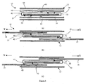
Figures 4(a) to 4(c) are schematic cross-sections on line A-A of the box ofFigure 1(a) , when the tab members are (a) in a closed position, (b) open in the first direction, and (c) open in the second direction; -
Figures 5(a) to 5(c) are cross-sections similar to those ofFigure 4 , but of an alternative embodiment of the invention; -
Figures 6(a) to 6(c) are cross-sections similar to those ofFigures 4 and5 , but of a further embodiment of the invention; -
Figure 7 is a plan view of a blank of a sleeve of a box according to any embodiment of the invention; and -
Figure 8 is a plan view of a blank of a variant of the sleeve ofFigure 7 . - Referring initially to
Figures 1 and2 , there is shown abox 10 suitable for packaging and/or for display purposes. Thebox 10 includes a hollow rectangular body orsleeve 12 defining a through passage for housing afirst tab member 14 and asecond tab member 16. As can best be seen inFigure 3(a) , thesleeve 12 has anupper wall 18, alower wall 20, twoside walls open ends box 10 also includes aplanar divider 30 extending across the passage, between theopen ends sleeve 12, and dividing the passage into upper and lower passages. Thetab members sleeve 12. Thefirst tab member 14 is housed in the lower passage, and thesecond tab member 16 is housed in the upper passage. Thetab members divider 30 and thesleeve 12, towards and away from one another. - As can be most clearly seen in
Figures 2 and3(b) , thedivider 30 has upper andlower faces side edges ends divider 30 has a band orbelt 42, narrower than thedivider 30, which extends around thedivider 30 on a belt path (shown only inFigure 3(b) ) defined by thedivider 30. The ends of thebelt 42 are joined to form a continuous loop. The belt path is defined by a waist across the twoends portions 44 at eachend divider 30 which serves to restrain thebelt 42 against lateral movement with respect to thedivider 30. Thedivider 30 is attached or bonded to thesleeve 12 by means of adhesive (not shown) located adjacent to theside edges divider 30, or in any other convenient position. Alternatively, thedivider 30 and thesleeve 12 may be integral. - The
belt 42 is typically a strip of a low-friction sheet material such as plastics film, e.g. Cellophane (TM) or Treofan GND (TM), or a material with a low-friction coating such as PTFE. The belt material is selected so that thebelt 42 can slide easily about thedivider 30. - The
first tab member 14 is attached to thebelt 42 by afirst bond 45, and thesecond tab member 16 is attached to thebelt 42 by asecond bond 46; thebonds first tab member 14 is in the form of a tray and may be used to contain item(s) such as items of clothing, jewellery, mobile telephones and associated accessories, cigarettes, compact discs, digital video discs, mini-discs, electronic components, pharmaceutical products, confectionery, chocolate, cosmetics and any other products which can be packaged in trays. As shown inFigure 3(c) thefirst tab member 14 comprises twocompartments 48, each of which is covered by alid 50, which is optional. Thefirst tab member 14 including itslids 50 may be printed with information, such as information about CD tracks, data on a CD, mobile telephone usage instructions or information about medicine contained within the tray. Alternatively, thesecond tab member 16 may only be in the form of a tray or bothtab members tab members tab members box 10 can be used as a display device and/or promotional tool. - When the
first tab member 14 is pushed or pulled in the direction of arrow X from the fully closed position (as shown inFigure 1(a) ), thetab member 14 causes thebelt 42 to turn about thedivider 30 so that thesecond tab member 16 moves in the direction of arrow Y, away from thefirst tab member 14, towards a first open position as shown inFigure 1(b) . When thefirst tab member 14 is then pushed or pulled in the opposite direction (in the direction of arrow Y) back into thesleeve 12, thebelt 42 is again caused to turn about thedivider 30 in the opposite direction so that thesecond tab member 16 moves in the direction of arrow X, until both members are back in the fully closed position. Continued movement of thefirst tab member 14 in the direction of arrow Y causes thebelt 42 to continue to turn about the divider until thetab members Figure 1(c) ) where thefirst tab member 14 is fully extended in the Y direction and thesecond tab member 16 is fully extended in the X direction. - The
tab members bonds tab members belt 42. In the embodiment shown inFigures 1 ,2 and4 , when in the fully closed position, the starting positions of thebonds divider 30 and the lengths of thetab members tab members Figures 1(b) and (c) . In the first fully open position shown inFigure 1(b) , the first andsecond tab members sleeve 12 in the X and Y directions respectively, and in the second fully open position shown inFigure 1(c) the first andsecond tab members sleeve 12 in the Y and X directions respectively. Thetab members bonds divider 30. By virtue of the starting positions of thebonds tab members - A more detailed illustration of the relative movement between the
tab members divider 30 can be seen inFigure 4 . When a user pulls/pushes thefirst tab member 14 in the direction of arrow X, thefirst tab member 14 causes thebelt 42 to translate relative to thedivider 30. The passage of thebelt 42 causes thesecond tab member 16 to move in the direction of arrow Y. When thebonds divider 30, as shown inFigure 4(b) , thefirst tab member 14 can be pulled/pushed no further in the direction of arrow X, and thesecond tab member 16 is then in one of the fully open positions (Figure 4(b) ). In other words, when thefirst tab member 14 is pulled out of thesleeve 12, translation of thebelt 42 around thedivider 30 stops when thebond 45 reaches the end of the belt path at the end of thedivider 30. - When the user pushes the
first tab member 14 in the direction of arrow Y, thefirst tab member 14 causes thebelt 42 to translate in the opposite sense, so that thesecond tab member 16 moves in the direction of arrow X. Thefirst tab member 14 can be pushed no further in the direction of arrow Y when thebonds divider 30, as shown inFigure 4(c) . In other words, when thefirst tab member 14 is pushed back into thesleeve 12, translation of thebelt 42 stops when thebond 45 reaches the end of the belt path at the end of thedivider 30. If required the user can push thesecond tab member 16 in the direction of arrow Y to the fully closed position. The effect is the same, in that both the first andsecond tab members - In this embodiment, the distance between opposite ends of the belt path of the
divider 30 defines the maximum movement of each of the first andsecond tab members second tab members upper faces divider 30 is delimited by thebonds divider 30. The length of the belt path must therefore be chosen such that the travel of thetab members tab members -
Figure 5 shows an embodiment of the invention in which thebonds tab members Figure 5(a) ). Thebonds divider 30 orthogonally at a position substantially midway between theends Figure 5(b) , thefirst tab member 14 can be moved in the direction of arrow X, causing thesecond tab member 16 to move in the direction of arrow Y, by a first maximum amount before therespective bonds tab members box 10 inFigure 5(b) is in a first fully open position, with thetab members sleeve 12 to a first maximum extent as indicated by the double-headedarrows 47. - Referring now to
Figure 5(c) , thefirst tab member 14 can be moved in the direction of arrow Y, causing thesecond tab member 16 to move in the direction of arrow X, by a second maximum amount before therespective bonds tab members box 10 inFigure 5(c) is in a second fully open position, with thetab members sleeve 12, to a second maximum extent as indicated by the double-headedarrows 49. - From a comparison of
Figures 5(b) and (c) , it can be seen that thefirst tab member 14 can be moved to a greater extent in the direction of arrow X than in the direction of arrow Y, whereas thesecond tab member 16 can be moved to a greater extent in the direction of arrow Y than in the direction of arrow X; in other words, the first maximum amount is greater than the second maximum amount. This asymmetry results from the offset of thebonds Figure 4(a) , and enables thetab members sleeve 12 to a greater extent when thebox 10 is in the first fully open position (Figure 5(b) ), than when thebox 10 is in the second fully open position (Figure 5(c) ). - A further embodiment of the invention is shown in
Figure 6 , in which thebonds Figure 6(b) , movement of thefirst tab member 14 in the direction of arrow X, and movement of thesecond tab member 16 in the direction of arrow Y, is delimited by thesecond bond 46 reaching anend 37 of the belt path, despite thefirst bond 45 not reaching theother end 39 of the belt path. At this point, thebox 10 is in the first fully open position, whereby thetab members sleeve 12 to a first maximum extent as indicated by the double-headedarrows 47. - As shown in
Figure 6(c) , movement of thefirst tab member 14 in the direction of arrow Y, and movement of thesecond tab member 16 in the direction of arrow X, is delimited by thefirst bond 45 reaching anend 37 of the belt path despite thesecond bond 46 not reaching theother end 39 of the belt path. At this point, thebox 10 is in the second fully open position, whereby thetab members sleeve 12 to a second maximum extent as indicated by the double-headedarrows 49. The secondmaximum extent 49 is less than the first maximum extent 47 (Figure 6(b) ), and again this asymmetry results from the offsetbonds Figure 6(a) . - To summarise, the
bonds divider 30. Offsetting thebonds tab members - As shown in
Figure 7 , thesleeve 12 can be made by folding and gluing a single flat blank manufactured by cutting and creasing from a sheet material such as plastic, cardboard or folding box board, as can be seen inFigure 5 . The blank comprises threepanels lines panel 76 is folded over and is attached to the underside ofpanel 80 to form the lower wall of the sleeve. The portions betweenscore lines side walls sleeve 12. - By virtue of corresponding cut-outs at an end of each of the
panels sleeve 12 has an oblong cut-out 90 portion at one end. This cut-out 90 enables the user of thebox 10 to hold an end portion of one of the first orsecond tab members Figure 8 , theupper wall 18 of thesleeve 12 has a semi-circular cut-out 92 at the same end as the cut-out 90. This further eases grasping of atab member - The
sleeve 12 can have a finish applied by foil blocking and embossing. The box/packaging could be provided with a wipe-clean finish by printing a varnish onto the print surface or by film laminating. Preferably, there is no forcible locking device on the packaging, so that the product can be loaded or unloaded easily, making the package suitable for the elderly and infirm. - The present invention may be embodied in other specific forms without departing from its essential attributes as defined in the appended claims. For example, the belts need not be continuous loops but could be strips associated with the tab members and arranged to co-operate with each other such that translation of one tab member causes the other tab member to move. The sleeve may be any other type of frame. The tab/
tray members sleeve 12; the tab/tray members tray members sleeve 12. The form of the first tab member may differ from that shown inFigure 3(c) , for example, it may have only one compartment, or it may have more than one compartment in the form of sub divisions or otherwise. The tab/tray members Figure 3(c) . The packaging can be made in many shapes and sizes and of various different materials, and is not limited to the shapes shown in the Figures.
Claims (15)
- A package (10) comprising:a belt (42) extending between a first end (37) and a second end (39) of a belt path; andfirst and second tab members (14, 16) attached to the belt (42) such that when the first tab member (14) is moved in a first direction, the second tab member (16) is driven by the belt (42) to move in a second direction different to the first direction;wherein the tab members (14, 16) are attached to the belt by respective bonds (45, 46), the movement of the tab members (14, 16) in either direction being delimited by at least one bond (45, 46) reaching an end of the belt path;characterised in that when at least one of the tab members (14, 16) is in a closed position, the associated bond (45, 46) is positioned inwardly from the ends of the belt path so that said tab member (14, 16) can move in both the first and second directions from the closed position before the bond (45, 46) reaches an end of the belt path to delimit said movement.
- The package of Claim 1, wherein the bond (45, 46) that delimits movement of the or each tab member (14, 16) is positioned substantially midway between the ends (37, 39) of the belt path when at least one of the tab members (14, 16) is in the closed position.
- The package of Claim 1, wherein the respective bonds (45, 46) are offset from one another when each of the tab members is in its closed position.
- The package of Claim 3, wherein the bonds (45, 46) are substantially equidistant from a plane which intersects a divider (30) orthogonally at a position substantially midway between the ends (37, 39) of the belt path.
- The package of Claim 3, wherein the bonds (45, 46) are offset to different extents from a plane which intersects a divider (30) orthogonally at a position substantially midway between the ends (37, 39) of the belt path.
- The package of any of Claims 3 to 5, wherein the tab members (14, 16) are arranged to be moveable to different maximum extents in the first and second directions respectively.
- The package of any preceding Claim, wherein when one of the tab members (14, 16) is in its closed position, said tab member (14, 16) overlies the belt path.
- The package of Claim 7, wherein when both of the tab members (14, 16) are in their closed positions, the tab members (14, 16) together sandwich the belt path.
- The package of Claim 7 or Claim 8, wherein the or each tab member (14, 16) is longer than or equal to the length of the belt path.
- The package of any preceding Claim and further comprising a sleeve (12) having opposed open ends (26, 28), wherein at least one of the tab members (14, 16) is wholly or substantially within the sleeve (12) when in the closed position and can protrude from the sleeve (12) through one or other of the open ends (26, 28) when moved in either of the first and second directions.
- The package of Claim 10, wherein the or each tab member (14, 16) is shorter than or equal to the length of the sleeve (12) and comprises an extended portion which projects from the sleeve (12) when the or each tab member (14, 16) is in the closed position.
- The package of Claim 10 or Claim 11, wherein when both of the tab members (14, 16) are in their closed positions, upper and lower walls (18, 20) of the sleeve (12) together sandwich the tab members (14, 16) and the belt path.
- The package of any preceding claim, wherein the first and second directions are opposing directions whereby the first and second tab members (14, 16) are caused to move away from and towards each other.
- The package of any preceding claim, wherein the belt (42) is a continuous loop which extends around a planar divider (30).
- The package of any preceding claim, wherein at least one tab member (14, 16) consists of or comprises a blister pack or a tray.
Applications Claiming Priority (2)
| Application Number | Priority Date | Filing Date | Title |
|---|---|---|---|
| GB0601300A GB0601300D0 (en) | 2005-07-11 | 2006-01-23 | Improvements to packaging |
| PCT/GB2007/000223 WO2007083156A1 (en) | 2006-01-23 | 2007-01-23 | Drawer-and-shell type package |
Publications (2)
| Publication Number | Publication Date |
|---|---|
| EP1984264A1 EP1984264A1 (en) | 2008-10-29 |
| EP1984264B1 true EP1984264B1 (en) | 2013-12-25 |
Family
ID=37991584
Family Applications (1)
| Application Number | Title | Priority Date | Filing Date |
|---|---|---|---|
| EP07704998.9A Active EP1984264B1 (en) | 2006-01-23 | 2007-01-23 | Drawer-and-shell type package |
Country Status (10)
| Country | Link |
|---|---|
| EP (1) | EP1984264B1 (en) |
| JP (1) | JP2009523675A (en) |
| KR (1) | KR20080107391A (en) |
| CN (1) | CN101395065B (en) |
| BR (1) | BRPI0706953A2 (en) |
| IL (1) | IL192961A0 (en) |
| MX (1) | MX2008009433A (en) |
| RU (1) | RU2390483C1 (en) |
| WO (2) | WO2007083156A1 (en) |
| ZA (1) | ZA200807214B (en) |
Families Citing this family (19)
| Publication number | Priority date | Publication date | Assignee | Title |
|---|---|---|---|---|
| GB0608845D0 (en) * | 2006-05-04 | 2006-06-14 | Burgopak Ltd Uk | Production of band-driven packages and their components |
| GB0716146D0 (en) | 2006-12-19 | 2007-09-26 | Duff Design Ltd | Improvements relating to packaging |
| DE102008040046A1 (en) * | 2008-07-01 | 2010-01-07 | Robert Bosch Gmbh | Reclosable pack |
| JP5275716B2 (en) * | 2008-07-31 | 2013-08-28 | 株式会社吉野工業所 | Container with handle |
| WO2010015638A1 (en) * | 2008-08-04 | 2010-02-11 | N.V. Organon | Child resistant package |
| EP2202164A1 (en) * | 2008-12-11 | 2010-06-30 | Philip Morris Products S.A. | Container with additional external panel |
| IT1398244B1 (en) * | 2010-03-09 | 2013-02-22 | Gd Spa | PACK OF CIGARETTES. |
| GB2490524A (en) | 2011-05-04 | 2012-11-07 | Duff Design Ltd | Band-drive package |
| ES2563322T3 (en) * | 2012-11-03 | 2016-03-14 | Reemtsma Cigarettenfabriken Gmbh | Package with sliding compartments for tobacco-related items |
| US9412104B2 (en) | 2012-12-28 | 2016-08-09 | Target Brands, Inc. | Transaction product with movable member |
| US9682793B2 (en) * | 2014-01-21 | 2017-06-20 | Nokia Technologies Oy | Product package with product mechanism |
| CN105775305A (en) * | 2016-04-22 | 2016-07-20 | 李玉安 | Push-and-pull accommodation box |
| RU171411U1 (en) * | 2016-09-14 | 2017-05-30 | АВР Интернатионал Лимитед | SLIDING TYPE PACKAGING FOR SMALL ITEMS HAVING A TRANSPORT SEALED PROVISION |
| US10513370B1 (en) * | 2016-10-21 | 2019-12-24 | Google Llc | Product packaging |
| CN106429051A (en) * | 2016-12-16 | 2017-02-22 | 安徽三联木艺包装有限公司 | Synchronization push-pull type cigarette box composed of three cavities |
| CN106742565B (en) * | 2017-02-23 | 2021-04-20 | 东莞当纳利印刷有限公司 | Process for realizing transmission mechanism of two-stage lifting table of fine box |
| CN109178679A (en) * | 2018-11-13 | 2019-01-11 | 湖北中烟工业有限责任公司 | The automatic-opening two-chamber cigarette case of unilateral pull or so |
| CN109229756A (en) * | 2018-11-15 | 2019-01-18 | 开平市梦妮莎食品有限公司 | A kind of chocolate displaying case |
| GB2582741B (en) | 2019-03-13 | 2021-11-10 | Burgopak Ltd | Packaging insert |
Family Cites Families (13)
| Publication number | Priority date | Publication date | Assignee | Title |
|---|---|---|---|---|
| GB304449A (en) * | 1927-12-31 | 1929-01-24 | Frank Mousley | Improvements in and relating to boxes or containers with sliding drawers |
| CH370699A (en) * | 1961-07-10 | 1963-07-15 | Jehouda Daniel | Packaging |
| GB9625419D0 (en) * | 1996-12-06 | 1997-01-22 | Wilkins Andre P | A container box |
| JP2000085749A (en) * | 1998-09-09 | 2000-03-28 | Dainippon Printing Co Ltd | Packaging case |
| CN2355989Y (en) * | 1998-11-09 | 1999-12-29 | 湛江新瑞旺食品有限公司 | Quantitative convenient taking article packaging box |
| AU767858B2 (en) * | 1998-12-24 | 2003-11-27 | Duff Design Limited | Sliding tray packaging |
| JP2001158421A (en) * | 1999-12-01 | 2001-06-12 | Rengo Co Ltd | Slide box |
| CN2496772Y (en) * | 2001-06-05 | 2002-06-26 | 上海烟草(集团)公司 | Drawer-tye packaging box |
| JP2003312641A (en) * | 2002-04-24 | 2003-11-06 | Meijiya Shoten:Kk | Shoes-packaging box |
| DE10218558A1 (en) * | 2002-04-25 | 2003-11-06 | Focke & Co | Cigarette pack with slider and sleeve |
| EP1466844A1 (en) * | 2003-04-11 | 2004-10-13 | Philip Morris Products S.A. | Package with sliding lid |
| CN2683579Y (en) * | 2003-12-29 | 2005-03-09 | 上海冠生园食品有限公司 | Bidirectional drawing type external packing box for rolled candy |
| GB0601300D0 (en) * | 2005-07-11 | 2006-03-01 | Burgopak Ltd Uk | Improvements to packaging |
-
2007
- 2007-01-23 MX MX2008009433A patent/MX2008009433A/en active IP Right Grant
- 2007-01-23 JP JP2008551862A patent/JP2009523675A/en active Pending
- 2007-01-23 BR BRPI0706953-7A patent/BRPI0706953A2/en not_active IP Right Cessation
- 2007-01-23 WO PCT/GB2007/000223 patent/WO2007083156A1/en active Application Filing
- 2007-01-23 WO PCT/GB2007/000203 patent/WO2007083151A1/en active Application Filing
- 2007-01-23 EP EP07704998.9A patent/EP1984264B1/en active Active
- 2007-01-23 CN CN2007800033253A patent/CN101395065B/en not_active Expired - Fee Related
- 2007-01-23 KR KR1020087020752A patent/KR20080107391A/en not_active Application Discontinuation
- 2007-01-23 RU RU2008134069/12A patent/RU2390483C1/en not_active IP Right Cessation
-
2008
- 2008-07-22 IL IL192961A patent/IL192961A0/en unknown
- 2008-08-21 ZA ZA200807214A patent/ZA200807214B/en unknown
Also Published As
| Publication number | Publication date |
|---|---|
| EP1984264A1 (en) | 2008-10-29 |
| CN101395065B (en) | 2012-05-30 |
| WO2007083151A1 (en) | 2007-07-26 |
| JP2009523675A (en) | 2009-06-25 |
| RU2008134069A (en) | 2010-02-27 |
| BRPI0706953A2 (en) | 2011-04-12 |
| ZA200807214B (en) | 2009-08-26 |
| KR20080107391A (en) | 2008-12-10 |
| IL192961A0 (en) | 2009-02-11 |
| RU2390483C1 (en) | 2010-05-27 |
| MX2008009433A (en) | 2008-09-10 |
| CN101395065A (en) | 2009-03-25 |
| WO2007083156A1 (en) | 2007-07-26 |
Similar Documents
| Publication | Publication Date | Title |
|---|---|---|
| EP1984264B1 (en) | Drawer-and-shell type package | |
| US8225931B2 (en) | Drawer-and-shell type package | |
| AU767858B2 (en) | Sliding tray packaging | |
| US8312993B2 (en) | Container for housing a tray or blister pack | |
| EP2154078B1 (en) | Packaging with sliding blister | |
| EP2174879A1 (en) | Comestible product dispenser | |
| WO2007007094A1 (en) | Improvements to packaging | |
| JP2007531673A (en) | Edible product dispenser and its production and use | |
| CA2633262C (en) | Comestible product dispensers and methods of making and using same | |
| CA2639984C (en) | Drawer-and-shell type package | |
| JP7192340B2 (en) | Opening and closing boxes and box-type packaged foods |
Legal Events
| Date | Code | Title | Description |
|---|---|---|---|
| PUAI | Public reference made under article 153(3) epc to a published international application that has entered the european phase |
Free format text: ORIGINAL CODE: 0009012 |
|
| 17P | Request for examination filed |
Effective date: 20080818 |
|
| AK | Designated contracting states |
Kind code of ref document: A1 Designated state(s): AT BE BG CH CY CZ DE DK EE ES FI FR GB GR HU IE IS IT LI LT LU LV MC NL PL PT RO SE SI SK TR |
|
| AX | Request for extension of the european patent |
Extension state: AL BA HR MK RS |
|
| REG | Reference to a national code |
Ref country code: HK Ref legal event code: DE Ref document number: 1128014 Country of ref document: HK |
|
| 17Q | First examination report despatched |
Effective date: 20111117 |
|
| GRAP | Despatch of communication of intention to grant a patent |
Free format text: ORIGINAL CODE: EPIDOSNIGR1 |
|
| INTG | Intention to grant announced |
Effective date: 20130701 |
|
| GRAS | Grant fee paid |
Free format text: ORIGINAL CODE: EPIDOSNIGR3 |
|
| GRAA | (expected) grant |
Free format text: ORIGINAL CODE: 0009210 |
|
| AK | Designated contracting states |
Kind code of ref document: B1 Designated state(s): AT BE BG CH CY CZ DE DK EE ES FI FR GB GR HU IE IS IT LI LT LU LV MC NL PL PT RO SE SI SK TR |
|
| AX | Request for extension of the european patent |
Extension state: AL BA HR MK RS |
|
| REG | Reference to a national code |
Ref country code: GB Ref legal event code: FG4D |
|
| REG | Reference to a national code |
Ref country code: CH Ref legal event code: EP |
|
| REG | Reference to a national code |
Ref country code: AT Ref legal event code: REF Ref document number: 646481 Country of ref document: AT Kind code of ref document: T Effective date: 20140115 |
|
| REG | Reference to a national code |
Ref country code: IE Ref legal event code: FG4D |
|
| REG | Reference to a national code |
Ref country code: DE Ref legal event code: R096 Ref document number: 602007034421 Country of ref document: DE Effective date: 20140213 |
|
| PG25 | Lapsed in a contracting state [announced via postgrant information from national office to epo] |
Ref country code: LT Free format text: LAPSE BECAUSE OF FAILURE TO SUBMIT A TRANSLATION OF THE DESCRIPTION OR TO PAY THE FEE WITHIN THE PRESCRIBED TIME-LIMIT Effective date: 20131225 Ref country code: FI Free format text: LAPSE BECAUSE OF FAILURE TO SUBMIT A TRANSLATION OF THE DESCRIPTION OR TO PAY THE FEE WITHIN THE PRESCRIBED TIME-LIMIT Effective date: 20131225 Ref country code: SE Free format text: LAPSE BECAUSE OF FAILURE TO SUBMIT A TRANSLATION OF THE DESCRIPTION OR TO PAY THE FEE WITHIN THE PRESCRIBED TIME-LIMIT Effective date: 20131225 |
|
| REG | Reference to a national code |
Ref country code: NL Ref legal event code: VDEP Effective date: 20131225 |
|
| REG | Reference to a national code |
Ref country code: AT Ref legal event code: MK05 Ref document number: 646481 Country of ref document: AT Kind code of ref document: T Effective date: 20131225 |
|
| REG | Reference to a national code |
Ref country code: LT Ref legal event code: MG4D |
|
| PG25 | Lapsed in a contracting state [announced via postgrant information from national office to epo] |
Ref country code: LV Free format text: LAPSE BECAUSE OF FAILURE TO SUBMIT A TRANSLATION OF THE DESCRIPTION OR TO PAY THE FEE WITHIN THE PRESCRIBED TIME-LIMIT Effective date: 20131225 |
|
| PG25 | Lapsed in a contracting state [announced via postgrant information from national office to epo] |
Ref country code: BE Free format text: LAPSE BECAUSE OF FAILURE TO SUBMIT A TRANSLATION OF THE DESCRIPTION OR TO PAY THE FEE WITHIN THE PRESCRIBED TIME-LIMIT Effective date: 20131225 Ref country code: EE Free format text: LAPSE BECAUSE OF FAILURE TO SUBMIT A TRANSLATION OF THE DESCRIPTION OR TO PAY THE FEE WITHIN THE PRESCRIBED TIME-LIMIT Effective date: 20131225 Ref country code: IS Free format text: LAPSE BECAUSE OF FAILURE TO SUBMIT A TRANSLATION OF THE DESCRIPTION OR TO PAY THE FEE WITHIN THE PRESCRIBED TIME-LIMIT Effective date: 20140425 |
|
| REG | Reference to a national code |
Ref country code: DE Ref legal event code: R119 Ref document number: 602007034421 Country of ref document: DE |
|
| PG25 | Lapsed in a contracting state [announced via postgrant information from national office to epo] |
Ref country code: CZ Free format text: LAPSE BECAUSE OF FAILURE TO SUBMIT A TRANSLATION OF THE DESCRIPTION OR TO PAY THE FEE WITHIN THE PRESCRIBED TIME-LIMIT Effective date: 20131225 Ref country code: RO Free format text: LAPSE BECAUSE OF FAILURE TO SUBMIT A TRANSLATION OF THE DESCRIPTION OR TO PAY THE FEE WITHIN THE PRESCRIBED TIME-LIMIT Effective date: 20131225 Ref country code: ES Free format text: LAPSE BECAUSE OF FAILURE TO SUBMIT A TRANSLATION OF THE DESCRIPTION OR TO PAY THE FEE WITHIN THE PRESCRIBED TIME-LIMIT Effective date: 20131225 Ref country code: CY Free format text: LAPSE BECAUSE OF FAILURE TO SUBMIT A TRANSLATION OF THE DESCRIPTION OR TO PAY THE FEE WITHIN THE PRESCRIBED TIME-LIMIT Effective date: 20131225 Ref country code: PT Free format text: LAPSE BECAUSE OF FAILURE TO SUBMIT A TRANSLATION OF THE DESCRIPTION OR TO PAY THE FEE WITHIN THE PRESCRIBED TIME-LIMIT Effective date: 20140428 Ref country code: NL Free format text: LAPSE BECAUSE OF FAILURE TO SUBMIT A TRANSLATION OF THE DESCRIPTION OR TO PAY THE FEE WITHIN THE PRESCRIBED TIME-LIMIT Effective date: 20131225 Ref country code: LU Free format text: LAPSE BECAUSE OF FAILURE TO SUBMIT A TRANSLATION OF THE DESCRIPTION OR TO PAY THE FEE WITHIN THE PRESCRIBED TIME-LIMIT Effective date: 20140123 Ref country code: PL Free format text: LAPSE BECAUSE OF FAILURE TO SUBMIT A TRANSLATION OF THE DESCRIPTION OR TO PAY THE FEE WITHIN THE PRESCRIBED TIME-LIMIT Effective date: 20131225 Ref country code: AT Free format text: LAPSE BECAUSE OF FAILURE TO SUBMIT A TRANSLATION OF THE DESCRIPTION OR TO PAY THE FEE WITHIN THE PRESCRIBED TIME-LIMIT Effective date: 20131225 Ref country code: SK Free format text: LAPSE BECAUSE OF FAILURE TO SUBMIT A TRANSLATION OF THE DESCRIPTION OR TO PAY THE FEE WITHIN THE PRESCRIBED TIME-LIMIT Effective date: 20131225 |
|
| REG | Reference to a national code |
Ref country code: CH Ref legal event code: PL |
|
| PG25 | Lapsed in a contracting state [announced via postgrant information from national office to epo] |
Ref country code: MC Free format text: LAPSE BECAUSE OF FAILURE TO SUBMIT A TRANSLATION OF THE DESCRIPTION OR TO PAY THE FEE WITHIN THE PRESCRIBED TIME-LIMIT Effective date: 20131225 |
|
| PG25 | Lapsed in a contracting state [announced via postgrant information from national office to epo] |
Ref country code: DK Free format text: LAPSE BECAUSE OF FAILURE TO SUBMIT A TRANSLATION OF THE DESCRIPTION OR TO PAY THE FEE WITHIN THE PRESCRIBED TIME-LIMIT Effective date: 20131225 Ref country code: DE Free format text: LAPSE BECAUSE OF NON-PAYMENT OF DUE FEES Effective date: 20140801 Ref country code: CH Free format text: LAPSE BECAUSE OF NON-PAYMENT OF DUE FEES Effective date: 20140131 Ref country code: LI Free format text: LAPSE BECAUSE OF NON-PAYMENT OF DUE FEES Effective date: 20140131 |
|
| PLBE | No opposition filed within time limit |
Free format text: ORIGINAL CODE: 0009261 |
|
| REG | Reference to a national code |
Ref country code: FR Ref legal event code: ST Effective date: 20140930 |
|
| STAA | Information on the status of an ep patent application or granted ep patent |
Free format text: STATUS: NO OPPOSITION FILED WITHIN TIME LIMIT |
|
| REG | Reference to a national code |
Ref country code: IE Ref legal event code: MM4A |
|
| REG | Reference to a national code |
Ref country code: DE Ref legal event code: R119 Ref document number: 602007034421 Country of ref document: DE Effective date: 20140801 |
|
| GBPC | Gb: european patent ceased through non-payment of renewal fee |
Effective date: 20140325 |
|
| PG25 | Lapsed in a contracting state [announced via postgrant information from national office to epo] |
Ref country code: FR Free format text: LAPSE BECAUSE OF NON-PAYMENT OF DUE FEES Effective date: 20140225 |
|
| 26N | No opposition filed |
Effective date: 20140926 |
|
| PG25 | Lapsed in a contracting state [announced via postgrant information from national office to epo] |
Ref country code: GB Free format text: LAPSE BECAUSE OF NON-PAYMENT OF DUE FEES Effective date: 20140325 Ref country code: IE Free format text: LAPSE BECAUSE OF NON-PAYMENT OF DUE FEES Effective date: 20140123 |
|
| PG25 | Lapsed in a contracting state [announced via postgrant information from national office to epo] |
Ref country code: SI Free format text: LAPSE BECAUSE OF FAILURE TO SUBMIT A TRANSLATION OF THE DESCRIPTION OR TO PAY THE FEE WITHIN THE PRESCRIBED TIME-LIMIT Effective date: 20131225 |
|
| REG | Reference to a national code |
Ref country code: HK Ref legal event code: WD Ref document number: 1128014 Country of ref document: HK |
|
| PG25 | Lapsed in a contracting state [announced via postgrant information from national office to epo] |
Ref country code: BG Free format text: LAPSE BECAUSE OF FAILURE TO SUBMIT A TRANSLATION OF THE DESCRIPTION OR TO PAY THE FEE WITHIN THE PRESCRIBED TIME-LIMIT Effective date: 20131225 |
|
| PG25 | Lapsed in a contracting state [announced via postgrant information from national office to epo] |
Ref country code: IT Free format text: LAPSE BECAUSE OF FAILURE TO SUBMIT A TRANSLATION OF THE DESCRIPTION OR TO PAY THE FEE WITHIN THE PRESCRIBED TIME-LIMIT Effective date: 20131225 Ref country code: GR Free format text: LAPSE BECAUSE OF FAILURE TO SUBMIT A TRANSLATION OF THE DESCRIPTION OR TO PAY THE FEE WITHIN THE PRESCRIBED TIME-LIMIT Effective date: 20140326 |
|
| PG25 | Lapsed in a contracting state [announced via postgrant information from national office to epo] |
Ref country code: TR Free format text: LAPSE BECAUSE OF FAILURE TO SUBMIT A TRANSLATION OF THE DESCRIPTION OR TO PAY THE FEE WITHIN THE PRESCRIBED TIME-LIMIT Effective date: 20131225 Ref country code: HU Free format text: LAPSE BECAUSE OF FAILURE TO SUBMIT A TRANSLATION OF THE DESCRIPTION OR TO PAY THE FEE WITHIN THE PRESCRIBED TIME-LIMIT; INVALID AB INITIO Effective date: 20070123 |