EP1983759A1 - Estimation of separable adaptive interpolation filters for hybrid video coding - Google Patents
Estimation of separable adaptive interpolation filters for hybrid video coding Download PDFInfo
- Publication number
- EP1983759A1 EP1983759A1 EP07007994A EP07007994A EP1983759A1 EP 1983759 A1 EP1983759 A1 EP 1983759A1 EP 07007994 A EP07007994 A EP 07007994A EP 07007994 A EP07007994 A EP 07007994A EP 1983759 A1 EP1983759 A1 EP 1983759A1
- Authority
- EP
- European Patent Office
- Prior art keywords
- filter
- dimensional
- pel
- displacement
- video data
- Prior art date
- Legal status (The legal status is an assumption and is not a legal conclusion. Google has not performed a legal analysis and makes no representation as to the accuracy of the status listed.)
- Withdrawn
Links
Images


Classifications
-
- H—ELECTRICITY
- H04—ELECTRIC COMMUNICATION TECHNIQUE
- H04N—PICTORIAL COMMUNICATION, e.g. TELEVISION
- H04N19/00—Methods or arrangements for coding, decoding, compressing or decompressing digital video signals
- H04N19/10—Methods or arrangements for coding, decoding, compressing or decompressing digital video signals using adaptive coding
- H04N19/134—Methods or arrangements for coding, decoding, compressing or decompressing digital video signals using adaptive coding characterised by the element, parameter or criterion affecting or controlling the adaptive coding
- H04N19/136—Incoming video signal characteristics or properties
- H04N19/137—Motion inside a coding unit, e.g. average field, frame or block difference
-
- H—ELECTRICITY
- H04—ELECTRIC COMMUNICATION TECHNIQUE
- H04N—PICTORIAL COMMUNICATION, e.g. TELEVISION
- H04N19/00—Methods or arrangements for coding, decoding, compressing or decompressing digital video signals
- H04N19/50—Methods or arrangements for coding, decoding, compressing or decompressing digital video signals using predictive coding
- H04N19/503—Methods or arrangements for coding, decoding, compressing or decompressing digital video signals using predictive coding involving temporal prediction
- H04N19/51—Motion estimation or motion compensation
- H04N19/523—Motion estimation or motion compensation with sub-pixel accuracy
-
- H—ELECTRICITY
- H04—ELECTRIC COMMUNICATION TECHNIQUE
- H04N—PICTORIAL COMMUNICATION, e.g. TELEVISION
- H04N19/00—Methods or arrangements for coding, decoding, compressing or decompressing digital video signals
- H04N19/10—Methods or arrangements for coding, decoding, compressing or decompressing digital video signals using adaptive coding
- H04N19/102—Methods or arrangements for coding, decoding, compressing or decompressing digital video signals using adaptive coding characterised by the element, parameter or selection affected or controlled by the adaptive coding
- H04N19/117—Filters, e.g. for pre-processing or post-processing
-
- H—ELECTRICITY
- H04—ELECTRIC COMMUNICATION TECHNIQUE
- H04N—PICTORIAL COMMUNICATION, e.g. TELEVISION
- H04N19/00—Methods or arrangements for coding, decoding, compressing or decompressing digital video signals
- H04N19/10—Methods or arrangements for coding, decoding, compressing or decompressing digital video signals using adaptive coding
- H04N19/134—Methods or arrangements for coding, decoding, compressing or decompressing digital video signals using adaptive coding characterised by the element, parameter or criterion affecting or controlling the adaptive coding
- H04N19/136—Incoming video signal characteristics or properties
- H04N19/137—Motion inside a coding unit, e.g. average field, frame or block difference
- H04N19/139—Analysis of motion vectors, e.g. their magnitude, direction, variance or reliability
-
- H—ELECTRICITY
- H04—ELECTRIC COMMUNICATION TECHNIQUE
- H04N—PICTORIAL COMMUNICATION, e.g. TELEVISION
- H04N19/00—Methods or arrangements for coding, decoding, compressing or decompressing digital video signals
- H04N19/10—Methods or arrangements for coding, decoding, compressing or decompressing digital video signals using adaptive coding
- H04N19/134—Methods or arrangements for coding, decoding, compressing or decompressing digital video signals using adaptive coding characterised by the element, parameter or criterion affecting or controlling the adaptive coding
- H04N19/146—Data rate or code amount at the encoder output
- H04N19/147—Data rate or code amount at the encoder output according to rate distortion criteria
-
- H—ELECTRICITY
- H04—ELECTRIC COMMUNICATION TECHNIQUE
- H04N—PICTORIAL COMMUNICATION, e.g. TELEVISION
- H04N19/00—Methods or arrangements for coding, decoding, compressing or decompressing digital video signals
- H04N19/10—Methods or arrangements for coding, decoding, compressing or decompressing digital video signals using adaptive coding
- H04N19/169—Methods or arrangements for coding, decoding, compressing or decompressing digital video signals using adaptive coding characterised by the coding unit, i.e. the structural portion or semantic portion of the video signal being the object or the subject of the adaptive coding
- H04N19/17—Methods or arrangements for coding, decoding, compressing or decompressing digital video signals using adaptive coding characterised by the coding unit, i.e. the structural portion or semantic portion of the video signal being the object or the subject of the adaptive coding the unit being an image region, e.g. an object
- H04N19/174—Methods or arrangements for coding, decoding, compressing or decompressing digital video signals using adaptive coding characterised by the coding unit, i.e. the structural portion or semantic portion of the video signal being the object or the subject of the adaptive coding the unit being an image region, e.g. an object the region being a slice, e.g. a line of blocks or a group of blocks
-
- H—ELECTRICITY
- H04—ELECTRIC COMMUNICATION TECHNIQUE
- H04N—PICTORIAL COMMUNICATION, e.g. TELEVISION
- H04N19/00—Methods or arrangements for coding, decoding, compressing or decompressing digital video signals
- H04N19/10—Methods or arrangements for coding, decoding, compressing or decompressing digital video signals using adaptive coding
- H04N19/169—Methods or arrangements for coding, decoding, compressing or decompressing digital video signals using adaptive coding characterised by the coding unit, i.e. the structural portion or semantic portion of the video signal being the object or the subject of the adaptive coding
- H04N19/17—Methods or arrangements for coding, decoding, compressing or decompressing digital video signals using adaptive coding characterised by the coding unit, i.e. the structural portion or semantic portion of the video signal being the object or the subject of the adaptive coding the unit being an image region, e.g. an object
- H04N19/176—Methods or arrangements for coding, decoding, compressing or decompressing digital video signals using adaptive coding characterised by the coding unit, i.e. the structural portion or semantic portion of the video signal being the object or the subject of the adaptive coding the unit being an image region, e.g. an object the region being a block, e.g. a macroblock
-
- H—ELECTRICITY
- H04—ELECTRIC COMMUNICATION TECHNIQUE
- H04N—PICTORIAL COMMUNICATION, e.g. TELEVISION
- H04N19/00—Methods or arrangements for coding, decoding, compressing or decompressing digital video signals
- H04N19/46—Embedding additional information in the video signal during the compression process
-
- H—ELECTRICITY
- H04—ELECTRIC COMMUNICATION TECHNIQUE
- H04N—PICTORIAL COMMUNICATION, e.g. TELEVISION
- H04N19/00—Methods or arrangements for coding, decoding, compressing or decompressing digital video signals
- H04N19/80—Details of filtering operations specially adapted for video compression, e.g. for pixel interpolation
- H04N19/82—Details of filtering operations specially adapted for video compression, e.g. for pixel interpolation involving filtering within a prediction loop
Definitions
- the present invention relates to video data compression and in particular to the estimation of adaptive interpolation filters for motion compensation.
- Video data is being adopted in increasing numbers of applications, ranging from video-telephoning and video-conferencing to DVD and digital television.
- video data is being transmitted or recorded, a substantial amount of data has to be sent through conventional transmission channels of limited bandwidth or has to be stored on conventional storage media of limited capacity.
- it is inevitable to compress or reduce the volume of digital data.
- video encoding standards For the compression of video data, a plurality of video encoding standards has been developed. Such video standards are, for instance, ITU-T standards denoted with H.26x and ISO/IEC standards denoted with MPEG-x. The most up-to-date and advanced video encoding standard is currently the standard denoted as H.264/MPEG-4 AVC.
- the temporal prediction scheme employed by most state-of-the-art video coding standards is motion compensation.
- this prediction scheme one or more motion vectors are determined for each block of video data in order to describe image displacements caused be object and/or camera movements. Based on the motion vectors determined, the image content of one block may be predicted at least to a certain extend from the image content of previously coded blocks. The remaining discrepancy between the predicted and the actual image content is called the prediction error, which is then encoded together with the motion vectors rather than the actual image content. In this manner, a substantial reduction in the amount of information to be coded can be achieved for most "natural" video sequences.
- motion vectors with sub-pel resolution i.e., motion vectors that are not restricted to integer values relative to pixel positions but that may also point to a position "between" two pixels.
- motion vectors are determined at half-pel or quarter-pel resolution, i.e. with a resolution twice or four times as large as the original video resolution.
- motion vectors with sub-pel resolution may refer to positions in the reference image, which are located between the sampled positions
- interpolation is needed in order to compute the predicted image.
- a predetermined interpolation filter is employed for computing the required sub-pel pixel values.
- predetermined interpolation filters may be replaced by adaptive interpolation filters that are specifically adapted to statistical properties of the current video image. In this manner, aliasing artifacts and camera noise may be taken into account that are peculiar to the video data that is to be compressed.
- two-dimensional filters for image processing may be classified as being either separable or non-separable.
- Separable two-dimensional filters may be decomposed into two one-dimensional filters. Consecutive application of the two one-dimensional filters is then equivalent to applying the original two-dimensional filter. For non-separable filters no such one-dimensional filters can be found.
- Separable filters are advantageous in the sense that their application to an image is computationally less expensive due to the reduced number of coefficients.
- a 6x6-tap two-dimensional filter for instance has a total of 36 coefficients, whereas, in case of separability, the two one-dimensional filters have a total of only 6+6 coefficients.
- each coefficient of the two-dimensional separable filter is equivalent to the product of two coefficients of the two one-dimensional filters. Therefore, filter coefficients of the two one-dimensional filters are computationally more complex to determine.
- the aim of the present invention is to provide an efficient method for determining filter coefficients of a two-dimensional separable adaptive interpolation filter for motion compensation of a sequence of video images. It is a further aim of the present invention to provide a method for video data compression and a corresponding apparatus that employ a two-dimensional separable interpolation filter for adaptive filtering.
- an adaptive two-dimensional interpolation filter that is separable into a one-dimensional horizontal interpolation filter and a one-dimensional vertical interpolation filter and to determine filter coefficients of the first one-dimensional interpolation filter from blocks of video data having motion vectors that indicate a full-pel displacement in the interpolation direction of the second one-dimensional filter.
- the first one-dimensional filter may then be applied to the video image so as to obtain one-dimensionally interpolated blocks of video data.
- Filter coefficients of the second one-dimensional interpolation filter are then determined in a second step from interpolated blocks of video data having motion vectors that indicate a sub-pel displacement in the interpolation direction of the second one-dimensional filter.
- a method for determining filter coefficients of a two-dimensional adaptive interpolation filter for motion compensation of a sequence of video images is provided.
- the two-dimensional adaptive interpolation filter is separable into a first and a second one-dimensional filter, so that the first and the second one-dimensional filter perform interpolation along a first and a second direction, respectively.
- the first direction is either one of the horizontal and the vertical direction
- the second direction is either one of the horizontal and the vertical direction other than the first direction.
- the method comprises the steps of dividing the video images into a plurality of blocks; determining displacement vectors indicating image displacement between a current block and a previous block, said displacement vectors having a fractional-pel resolution; determining filter coefficients of the first one-dimensional filter based on blocks having first displacement vectors that indicate a sub-pel displacement in the first direction and a full-pel displacement in the second direction; and determining filter coefficients of the second one-dimensional filter based on blocks having second displacement vectors other than the first displacement vectors.
- the filter coefficients of the second one-dimensional filter are determined based on blocks having displacement vectors that indicate a full-pel displacement in the first direction and a sub-pel displacement in the second direction.
- the first one-dimensional filter is applied so as to obtain one-dimensionally interpolated blocks of video data, so that the filter coefficients of the second one-dimensional filter may be determined based on one-dimensionally interpolated blocks having displacement vectors that indicate a sub-pel displacement in the first direction and a sub-pel displacement in the second direction.
- filter coefficients are determined by computing a measure indicating accuracy of the motion compensation and by varying values of the filter coefficients so as to optimize the computed measure.
- the two-dimensional interpolation filter may be adapted to the image statistics so as to optimize motion compensation and therewith coding efficiency.
- filter coefficients are determined by solving a system of linear equations so as to determine values of the filter coefficients that optimize accuracy of the motion compensation.
- filter coefficients may be determined in a highly efficient manner without employing a computationally expensive numerical optimization algorithm.
- a method for video data compression comprises the steps of determining a displacement vector indicating image displacement between a current block of video data and a previous block of video data, said displacement vector having a fractional-pel resolution; obtaining filter coefficients of a two-dimensional adaptive interpolation filter by performing all steps of a method according to the first aspect of the present invention; obtaining pixel values at sub-pel positions indicated by the displacement vector by applying the two-dimensional adaptive interpolation filter to the previous block of video data; obtaining a prediction error signal by applying motion compensation to the current block of video data based on the obtained pixel values and the displacement vector; and generating compressed video data by encoding the prediction error signal and the filter coefficients.
- the step of obtaining pixel values further comprises a first interpolation step, wherein the first one-dimensional filter is applied to the previous block of video data so as to obtain pixel values that correspond to a one-dimensionally interpolated block of video data; and a second interpolation step, wherein the second one-dimensional filter is applied to the one-dimensionally interpolated block of video data.
- the two-dimensional adaptive interpolation filter may be applied in a computationally efficient manner.
- the first interpolation step does not affect a pixel value at a full-pel position.
- the second interpolation step preferably does not affect a pixel value at a full-pel position nor a pixel value obtained by the first interpolation step.
- pixel values at a certain sub-pel position are determined by applying a two-dimensional adaptive interpolation filter that is specific for the certain sub-pel position.
- the two-dimensional adaptive interpolation filter is a discrete filter that operates on pixels of the original image only, i.e., pixels at full-pel positions. If this filter is supposed to be generate more than only one interpolated sub-pel value for each full-pel pixel, such as in the case of quarter-pel resolution, the sub-pel position, where an interpolated pixel value needs to be obtained, has to be taken into account.
- a two-dimensional adaptive interpolation filter that is specific for a full-pel position in the first direction is determined by filter coefficients of the second one-dimensional filter only.
- a two-dimensional adaptive interpolation filter that is specific for a full-pel position in the second direction is determined by filter coefficients of the first one-dimensional filter only.
- interpolation has to be performed in one direction only, since full-pel pixels in the respective direction are already available.
- a two-dimensional adaptive interpolation filter that is specific for a sub-pel position in the first and the second direction comprises filter coefficients of the first and the second one-dimensional filter. In this case, no full-pel pixels are available so that interpolation has to be performed in both directions.
- the filter coefficients are obtained by exploiting symmetry properties between two different two-dimensional adaptive interpolation filters that are specific for two different sub-pel positions, respectively. Further, at least some of the filter coefficients are obtained by exploiting symmetry properties of the two-dimensional adaptive interpolation filter.
- the two-dimensional adaptive interpolation filter may be symmetric with respect to at least either one of horizontal and vertical mirroring. In this manner, the overhead for determining and transmitting filter coefficients may be reduced substantially.
- the step of obtaining filter coefficients is repeated for either one of every slice of video data, every video image, and every sequence of video images.
- the two-dimensional adaptive interpolation filter may be updated as needed in order to ensure that it is always optimally adapted to the current image statistics.
- an apparatus for encoding video data is provided. This apparatus is adapted to carry out all steps of a method according to any of the first and the second aspect of the present invention.
- a computer program product comprises a computer readable medium having computer readable program code embodied thereon, the program code being adapted to carry out all steps of a method according to any of the first and the second aspect of the present invention.
- the video encoder generally denoted by reference numeral 100, comprises a subtractor 110 for determining differences between a current block of a video image (input signal) and a prediction signal of the current block which is based on previously encoded blocks stored in memory 140.
- a transformation and quantization unit 120 transforms the resulting prediction error from the spatial domain to the frequency domain and quantizes the obtained transform coefficients.
- An entropy coding unit 190 entropy encodes the quantized transform coefficients.
- the input image is divided into macro blocks.
- the encoder 100 employs a Differential Pulse Code Modulation (DPCM) approach which only transmits differences between blocks of an input video sequence and their predictions based on previously encoded blocks ("the locally decoded image"). These differences are determined in subtractor 110, which receives the blocks to be encoded in order to subtract the prediction signal therefrom.
- DPCM Differential Pulse Code Modulation
- the locally decoded image is provided by a decoding unit incorporated into video encoder 100.
- the decoding unit performs the encoding steps in reverse manner.
- An inverse quantization and inverse transformation unit 130 dequantizes the quantized coefficients and applies an inverse transformation to the dequantized coefficients.
- adder 135 the decoded differences are added to the prediction signal to form the locally decoded image.
- a deblocking filter 137 reduces blocking artifacts in the decoded image.
- the type of prediction that is employed by video encoder 100 depends on whether the macro blocks are encoded in "Intra” or "Inter” mode.
- “Intra” mode the video encoding standard H.264/AVC uses a prediction scheme based on already encoded macro blocks of the same image in order to predict subsequent macro blocks.
- “Inter” mode motion compensated prediction between corresponding blocks of several consecutive frames is employed.
- Intra-encoded images Only Intra-encoded images (I-type images) can be decoded without reference to any previously decoded image.
- the I-type images provide error resilience for the encoded video sequence. Further, entry points into bit streams of encoded data are provided by the I-type images in order to enable a random access, i.e. to access I-type images within the sequence of encoded video images.
- a switch between Intra-mode, i.e. a processing by Intra-frame prediction unit 150, and Inter-mode, i.e. a processing by motion compensated prediction unit 160, is controlled by Intra/Inter switch 180.
- a macro block is predicted from corresponding blocks of previous frames by employing motion compensation.
- the estimation is accomplished by a motion estimator unit 170, receiving the current input signal and the locally decoded image.
- Motion estimation yields two-dimensional motion vectors, representing a pixel displacement between the current block and the corresponding block in previous frames.
- a motion compensated prediction unit 160 Based on the estimated motion, a motion compensated prediction unit 160 provides a prediction signal.
- motion vectors may be determined at sub-pel resolution, e.g. half-pel or quarter-pel resolution.
- a motion vector with sub-pel resolution may point to a position within a previous frame where no pixel value is available, i.e. a sub-pel position.
- spatial interpolation of pixel values is needed in order to perform motion compensation.
- a 6-tap Wiener interpolation filter with fixed filter coefficients and a bilinear filter is applied in order to obtain pixel values for sub-pel positions. The interpolation process is done as follows:
- the differences between the current and the predicted signal are transformed into transform coefficients by transformation / quantization unit 120.
- an orthogonal transformation such as a two-dimensional Discrete Cosine transformation (DCT) or an integer version thereof is employed.
- the transform coefficients are quantized in order to reduce the amount of data that has to be encoded.
- the step of quantization is controlled by quantization tables that specify the precision and therewith the number of bits that are used to encode each frequency coefficient. Lower frequency components are usually more important for image quality than fine details so that more bits are spent for coding the low frequency components than for the higher ones.
- the two-dimensional array of transform coefficients has to be converted into a one-dimensional string to pass it to the entropy encoder. This conversion is done by scanning the array in a predetermined sequence. The thus obtained one-dimensional sequence of quantized transform coefficients is compressed to a series of number pairs called run levels. Finally, the run-level sequence is coded with binary code words of variable length (Variable Length Code, VLC). The code is optimized to assign shorter code words to most frequent run-level pairs occurring in typical video images. The resulting bitstream is multiplexed with the motion information and stored on a recording medium or transmitted to the decoder side.
- VLC Variable Length Code
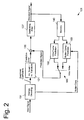
- FIG. 2 A schematic block diagram, illustrating the configuration of the corresponding decoder, is shown in Fig. 2 .
- decoder 101 of Fig. 2 first the entropy encoding of transform coefficients and motion data is reversed in an entropy decoding unit 191. This step also involves an inverse scanning in order to convert the sequence of decoded transform coefficients into a two-dimensional block of data as it is required for the inverse transformation.
- the decoded block of transform coefficients is then submitted to an inverse quantizer and inverse transformer 121 and the decoded motion data is sent to a motion compensated prediction unit 160.
- interpolation of pixel values may be needed in order to perform motion compensation.
- the result of the inverse transformation contains prediction differences and is added by adder 135 to the prediction signal stemming from the motion compensated prediction unit 160 in Inter-mode or stemming from an Intra-frame prediction unit 150 in Intra-mode.
- the reconstructed image may be passed through a deblocking filter 137 and the decoded signal is stored in memory 140 to be applied to prediction units 150, 160.
- Motion compensation may be improved by replacing the fixed interpolation filters employed by the motion compensated prediction unit 160 by filters that adapt to the statistical properties of the video images.
- Figure 3 is a block diagram of a video encoder employing motion compensation with adaptive filtering.
- the block diagram of Fig. 3 is similar to that of Fig. 1 , wherein like reference numerals denote like elements, a detailed description of which will be omitted.
- the motion compensated prediction unit 161 determines the adaptive interpolation filter required for compensation. To this end, motion compensated prediction unit 161 also receives a copy of the input signal. Moreover, coefficients of the thus determined adaptive interpolation filter are transmitted to the entropy coder 190 in order to be inserted into the output bitstream.
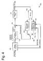
- Figure 4 is a block diagram of a video decoder employing motion compensation with adaptive filtering.
- the block diagram of Fig. 4 is similar to that of Fig. 2 , wherein like reference numerals denote like elements, a detailed description of which will be omitted.
- the motion compensated prediction unit 161 applies the adaptive interpolation filter upon compensating the current image.
- the motion compensated prediction unit 161 receives filter coefficients decoded from the input bitstream by means of the entropy decoder 191.
- Fig. 5 is a schematic drawing of a block of video data. Filled circles denote full-pel positions, i.e. sampling points of the original image, whereas open circles indicate sub-pel positions, at which pixel values have to be interpolated. Although the following figures illustrate quarter-pel resolution, the present invention may be applied to any particular fractional-pel resolution, including different sub-pel resolutions in vertical and horizontal direction.
- the original image (or block of video data) will be denoted by S x,y , which is the pixel value at full-pel position (x,y).
- the corresponding horizontally and vertically interpolated image will be denoted by S ⁇ ⁇ nx + p , ny + q .
- the pixel at full-pel position (nx, ny) in the interpolated image corresponds to pixel ( x, y ) in the original image.
- the components v x and v y refer to fractional-pel positions.
- a similar terminology will be used for the y-direction.
- a two-dimensional interpolation filter that may be separated into a one-dimensional horizontal interpolation filter g and a one-dimensional vertical interpolation filter h .
- a specific horizontal interpolation filter g ( p ) is defined for each sub-pel position; cf. Fig. 6 .
- the vertical filter coefficients do also depend on the particular sub-pel position ( p,q ).
- a specific vertical interpolation filter h ( p,q ) is defined for each sub-pel position ( p, q ) ; cf. Fig. 7 .
- the interpolation filter should yield the original values at fullpel positions.
- Horizontal filter coefficients g i p are now be determined as follows.
- P x,y denote the previously decoded reference image and
- the displacement vector denotes a full-pel displacement along the vertical direction.
- the remaining prediction error for this displacement may thus be expressed in terms of the horizontal filter coefficients alone, viz.
- the horizontal filter coefficients g i p are determined so as to minimize the prediction error of Eq. (5).
- the optimization may be performed by any numerical optimization algorithm known in the art, such as gradient descent, simulated annealing, etc.
- the optimum filter coefficients may be determined advantageously by solving a system of linear equations that results from computing the partial derivatives of Eq. (5) with respect to the filter coefficients g i p , viz.
- the vertical filter coefficients h j p ⁇ q are then determined in a second step by optimizing the prediction error that also takes vertical sub-pel displacements into account.
- the sum over x and y is to be taken over that region of the original image for which the displacement vector is valid.
- This region may correspond to the macro block, for which the displacement vector has been determined.
- this does not imply any practical restriction since only those interpolation filters are needed for image compensation anyway.
- Pixel values at sub-pel positions other than those of the displacement vector do not have to be computed.
- the optimization may be performed by any numerical optimization algorithm known in the art, such as gradient descent, simulated annealing, etc.
- the optimum filter coefficients may be determined advantageously by solving a system of linear equations that results from computing the partial derivatives of Eq. (8) with respect to the filter coefficients h j p ⁇ q , viz.
- the computational complexity of the method for estimating the filter coefficients according to the present invention is equivalent to a conventional matrix inversion.
- g i p and h j p ⁇ q denoted filter coefficients of the horizontal and the vertical interpolation filter, respectively, the horizontal interpolation filter being determined prior to the vertical interpolation filter.
- the role of g i p and h j p ⁇ q may also be exchanged so that the vertical filter is determined before the horizontal filter.
- the vertical interpolation filter h j p ⁇ q is allowed to depend on the horizontal sub-pel position p .
- similar advantages may also be achieved if the vertical interpolation filter h j p ⁇ q is replaced by h j p , i.e., by a vertical interpolation filter that is translational invariant in horizontal direction.
- the number of non-trivial vertical filters can be reduced to ( n -1), thus further reducing the signaling overhead.
- translational invariant coefficients h j q can be determined analogously to g i p , i.e. without first performing a horizontal interpolation.
- the sum over x and y may be taken over that region of the original image for which the displacement vector is valid.
- This region may correspond to the macro block, for which the displacement vector has been determined.
- the present invention is not restricted to the above symmetries and other symmetries, including rotational symmetries, may be exploited to reduce the overhead for determining and transmitting filter coefficients
- Fig. 10A and B show a comparison of the coding efficiency achieved with fixed filter (JM), with a conventional non-separable adaptive two-dimensional filter and with the separable adaptive filter of the present invention. It can be seen that the coding efficiency achieved with the inventive separable adaptive filter is similar to the coding efficiency achieved with the conventional non-separable filter. Both filtering methods offer significant gains compared to the fixed filter of H.264/AVC.
- the separable filter of the present invention further provides a substantial reduction of the computational complexity of the filtering itself, as it is illustrated in Fig. 11. Applying 6x6-tap two-dimensional non-separable filters requires 360 calculations for each coding block with quarter-pel resolution. With the separable 6-taps filter of the present invention, the number of calculations is reduced to 90.
- the present invention relates to a method for determining filter coefficients of a separable two-dimensional adaptive interpolation filter used for motion compensation with sub-pel resolution, a corresponding method for video data compression with adaptive filtering, and a corresponding apparatus.
- the two-dimensional interpolation filter is separated into a one-dimensional horizontal interpolation filter and a one-dimensional vertical interpolation filter.
- Filter coefficients of the first one-dimensional interpolation filter are determined from blocks of video data having motion vectors that indicate a full-pel displacement in the interpolation direction of the second one-dimensional filter.
- the first one-dimensional filter may then be applied to the video image so as to obtain one-dimensionally interpolated blocks of video data.
- Filter coefficients of the second one-dimensional interpolation filter are then determined in a second step from interpolated blocks of video data having motion vectors that indicate a sub-pel displacement in the interpolation direction of the second one-dimensional filter. According to this invention, filter coefficients can be determined in a highly efficient manner by solving systems of linear equations.
Landscapes
- Engineering & Computer Science (AREA)
- Multimedia (AREA)
- Signal Processing (AREA)
- Compression Or Coding Systems Of Tv Signals (AREA)
- Television Systems (AREA)
Abstract
Description
- The present invention relates to video data compression and in particular to the estimation of adaptive interpolation filters for motion compensation.
- Video data is being adopted in increasing numbers of applications, ranging from video-telephoning and video-conferencing to DVD and digital television. When video data is being transmitted or recorded, a substantial amount of data has to be sent through conventional transmission channels of limited bandwidth or has to be stored on conventional storage media of limited capacity. In order to transmit and store digital data on conventional channels/media, it is inevitable to compress or reduce the volume of digital data.
- For the compression of video data, a plurality of video encoding standards has been developed. Such video standards are, for instance, ITU-T standards denoted with H.26x and ISO/IEC standards denoted with MPEG-x. The most up-to-date and advanced video encoding standard is currently the standard denoted as H.264/MPEG-4 AVC.
- The encoding approach underlying most of these standards consists of the following main stages:
- (a) Dividing each individual video frame into two-dimensional blocks of pixels in order to subject each video frame to data compression at a block level.
- (b) Decorrelating spatiotemporal video information by applying a temporal prediction scheme to each block and by transforming the residual prediction error from the spatial domain into the frequency domain.
- (c) Reducing the overall amount of data by quantizing the resulting transform coefficients.
- (d) Compressing the remaining data by entropy encoding the quantized transform coefficients.
- The temporal prediction scheme employed by most state-of-the-art video coding standards is motion compensation. In this prediction scheme, one or more motion vectors are determined for each block of video data in order to describe image displacements caused be object and/or camera movements. Based on the motion vectors determined, the image content of one block may be predicted at least to a certain extend from the image content of previously coded blocks. The remaining discrepancy between the predicted and the actual image content is called the prediction error, which is then encoded together with the motion vectors rather than the actual image content. In this manner, a substantial reduction in the amount of information to be coded can be achieved for most "natural" video sequences.
- Obviously, compression efficiency depends critically on the accuracy of motion estimation. Modern video coding standards such as H.264/AVC thus allow for motion vectors with sub-pel resolution, i.e., motion vectors that are not restricted to integer values relative to pixel positions but that may also point to a position "between" two pixels. Usually, motion vectors are determined at half-pel or quarter-pel resolution, i.e. with a resolution twice or four times as large as the original video resolution.
- Since motion vectors with sub-pel resolution may refer to positions in the reference image, which are located between the sampled positions, interpolation is needed in order to compute the predicted image. Generally, a predetermined interpolation filter is employed for computing the required sub-pel pixel values.
- In order to further improve the prediction accuracy, and therewith compression efficiency, predetermined interpolation filters may be replaced by adaptive interpolation filters that are specifically adapted to statistical properties of the current video image. In this manner, aliasing artifacts and camera noise may be taken into account that are peculiar to the video data that is to be compressed.
- Generally, two-dimensional filters for image processing may be classified as being either separable or non-separable. Separable two-dimensional filters may be decomposed into two one-dimensional filters. Consecutive application of the two one-dimensional filters is then equivalent to applying the original two-dimensional filter. For non-separable filters no such one-dimensional filters can be found.
- Separable filters are advantageous in the sense that their application to an image is computationally less expensive due to the reduced number of coefficients. A 6x6-tap two-dimensional filter, for instance has a total of 36 coefficients, whereas, in case of separability, the two one-dimensional filters have a total of only 6+6 coefficients.
- On the other hand, each coefficient of the two-dimensional separable filter is equivalent to the product of two coefficients of the two one-dimensional filters. Therefore, filter coefficients of the two one-dimensional filters are computationally more complex to determine.
- The aim of the present invention is to provide an efficient method for determining filter coefficients of a two-dimensional separable adaptive interpolation filter for motion compensation of a sequence of video images. It is a further aim of the present invention to provide a method for video data compression and a corresponding apparatus that employ a two-dimensional separable interpolation filter for adaptive filtering.
- This is achieved by the features as set forth in the independent claims.
- Preferred embodiments are the subject matter of dependent claims.
- It is the particular approach of the present invention to employ an adaptive two-dimensional interpolation filter that is separable into a one-dimensional horizontal interpolation filter and a one-dimensional vertical interpolation filter and to determine filter coefficients of the first one-dimensional interpolation filter from blocks of video data having motion vectors that indicate a full-pel displacement in the interpolation direction of the second one-dimensional filter. The first one-dimensional filter may then be applied to the video image so as to obtain one-dimensionally interpolated blocks of video data. Filter coefficients of the second one-dimensional interpolation filter are then determined in a second step from interpolated blocks of video data having motion vectors that indicate a sub-pel displacement in the interpolation direction of the second one-dimensional filter.
- According to a first aspect of the present invention, a method for determining filter coefficients of a two-dimensional adaptive interpolation filter for motion compensation of a sequence of video images is provided. The two-dimensional adaptive interpolation filter is separable into a first and a second one-dimensional filter, so that the first and the second one-dimensional filter perform interpolation along a first and a second direction, respectively. The first direction is either one of the horizontal and the vertical direction, whereas the second direction is either one of the horizontal and the vertical direction other than the first direction. The method comprises the steps of dividing the video images into a plurality of blocks; determining displacement vectors indicating image displacement between a current block and a previous block, said displacement vectors having a fractional-pel resolution; determining filter coefficients of the first one-dimensional filter based on blocks having first displacement vectors that indicate a sub-pel displacement in the first direction and a full-pel displacement in the second direction; and determining filter coefficients of the second one-dimensional filter based on blocks having second displacement vectors other than the first displacement vectors.
- Preferably, the filter coefficients of the second one-dimensional filter are determined based on blocks having displacement vectors that indicate a full-pel displacement in the first direction and a sub-pel displacement in the second direction. Alternatively, the first one-dimensional filter is applied so as to obtain one-dimensionally interpolated blocks of video data, so that the filter coefficients of the second one-dimensional filter may be determined based on one-dimensionally interpolated blocks having displacement vectors that indicate a sub-pel displacement in the first direction and a sub-pel displacement in the second direction.
- Preferably, filter coefficients are determined by computing a measure indicating accuracy of the motion compensation and by varying values of the filter coefficients so as to optimize the computed measure. In this manner, the two-dimensional interpolation filter may be adapted to the image statistics so as to optimize motion compensation and therewith coding efficiency.
- Preferably, filter coefficients are determined by solving a system of linear equations so as to determine values of the filter coefficients that optimize accuracy of the motion compensation. In this manner, filter coefficients may be determined in a highly efficient manner without employing a computationally expensive numerical optimization algorithm.
- According to a second aspect of the present invention, a method for video data compression is provided. The method comprises the steps of determining a displacement vector indicating image displacement between a current block of video data and a previous block of video data, said displacement vector having a fractional-pel resolution; obtaining filter coefficients of a two-dimensional adaptive interpolation filter by performing all steps of a method according to the first aspect of the present invention; obtaining pixel values at sub-pel positions indicated by the displacement vector by applying the two-dimensional adaptive interpolation filter to the previous block of video data; obtaining a prediction error signal by applying motion compensation to the current block of video data based on the obtained pixel values and the displacement vector; and generating compressed video data by encoding the prediction error signal and the filter coefficients.
- Preferably, the step of obtaining pixel values further comprises a first interpolation step, wherein the first one-dimensional filter is applied to the previous block of video data so as to obtain pixel values that correspond to a one-dimensionally interpolated block of video data; and a second interpolation step, wherein the second one-dimensional filter is applied to the one-dimensionally interpolated block of video data. In this manner, the two-dimensional adaptive interpolation filter may be applied in a computationally efficient manner.
- Preferably, the first interpolation step does not affect a pixel value at a full-pel position. Further, the second interpolation step preferably does not affect a pixel value at a full-pel position nor a pixel value obtained by the first interpolation step.
- Preferably, pixel values at a certain sub-pel position are determined by applying a two-dimensional adaptive interpolation filter that is specific for the certain sub-pel position. The two-dimensional adaptive interpolation filter is a discrete filter that operates on pixels of the original image only, i.e., pixels at full-pel positions. If this filter is supposed to be generate more than only one interpolated sub-pel value for each full-pel pixel, such as in the case of quarter-pel resolution, the sub-pel position, where an interpolated pixel value needs to be obtained, has to be taken into account.
- Preferably, a two-dimensional adaptive interpolation filter that is specific for a full-pel position in the first direction is determined by filter coefficients of the second one-dimensional filter only. Similarly, a two-dimensional adaptive interpolation filter that is specific for a full-pel position in the second direction is determined by filter coefficients of the first one-dimensional filter only. For these two-dimensional adaptive interpolation filter interpolation has to be performed in one direction only, since full-pel pixels in the respective direction are already available. For a two-dimensional adaptive interpolation filter, however, that is specific for a sub-pel position in the first and the second direction comprises filter coefficients of the first and the second one-dimensional filter. In this case, no full-pel pixels are available so that interpolation has to be performed in both directions.
- Preferably, at least some of the filter coefficients are obtained by exploiting symmetry properties between two different two-dimensional adaptive interpolation filters that are specific for two different sub-pel positions, respectively. Further, at least some of the filter coefficients are obtained by exploiting symmetry properties of the two-dimensional adaptive interpolation filter. In particular, the two-dimensional adaptive interpolation filter may be symmetric with respect to at least either one of horizontal and vertical mirroring. In this manner, the overhead for determining and transmitting filter coefficients may be reduced substantially.
- Preferably, the step of obtaining filter coefficients is repeated for either one of every slice of video data, every video image, and every sequence of video images. In this manner, the two-dimensional adaptive interpolation filter may be updated as needed in order to ensure that it is always optimally adapted to the current image statistics.
- According to a third aspect of the present invention, an apparatus for encoding video data is provided. This apparatus is adapted to carry out all steps of a method according to any of the first and the second aspect of the present invention.
- According to a fourth aspect of the present invention, a computer program product is provided. The computer program product comprises a computer readable medium having computer readable program code embodied thereon, the program code being adapted to carry out all steps of a method according to any of the first and the second aspect of the present invention.
- The above and other objects and features of the present invention will become more apparent from the following description and preferred embodiments given in conjunction with the accompanying drawings, in which:
- Fig. 1
- is a block diagram of a conventional video encoder;
- Fig. 2
- is a block diagram of a conventional video decoder;
- Fig. 3
- is a block diagram of a video encoder applying motion compensation with adaptive filtering;
- Fig. 4
- is a block diagram of a video decoder applying motion compensation with adaptive filtering;
- Fig. 5
- is a schematic drawing of a block of video data;
- Fig. 6
- is a schematic drawing illustrating horizontal interpolation of the original block of video data;
- Fig. 7
- is a schematic drawing illustrating horizontal and vertical interpolation of the original block of video data;
- Fig. 8
- is a chart comparing coding efficiencies achieved by a conventional non-separable adaptive interpolation filter and the separable adaptive interpolation filter according to the present invention; and
- Fig.9
- is a chart comparing the computational complexity of applying the conventional non-separable adaptive interpolation filter and the separable adaptive interpolation filters according to the present invention.
- Referring to
Fig. 1 , an example of a conventional video encoder is illustrated. The video encoder, generally denoted byreference numeral 100, comprises asubtractor 110 for determining differences between a current block of a video image (input signal) and a prediction signal of the current block which is based on previously encoded blocks stored inmemory 140. A transformation andquantization unit 120 transforms the resulting prediction error from the spatial domain to the frequency domain and quantizes the obtained transform coefficients. Anentropy coding unit 190 entropy encodes the quantized transform coefficients. - In accordance with the H.264 / AVC standard, the input image is divided into macro blocks. The
encoder 100 employs a Differential Pulse Code Modulation (DPCM) approach which only transmits differences between blocks of an input video sequence and their predictions based on previously encoded blocks ("the locally decoded image"). These differences are determined insubtractor 110, which receives the blocks to be encoded in order to subtract the prediction signal therefrom. - The locally decoded image is provided by a decoding unit incorporated into
video encoder 100. The decoding unit performs the encoding steps in reverse manner. An inverse quantization andinverse transformation unit 130 dequantizes the quantized coefficients and applies an inverse transformation to the dequantized coefficients. Inadder 135, the decoded differences are added to the prediction signal to form the locally decoded image. Further, adeblocking filter 137 reduces blocking artifacts in the decoded image. - The type of prediction that is employed by
video encoder 100 depends on whether the macro blocks are encoded in "Intra" or "Inter" mode. In "Intra" mode the video encoding standard H.264/AVC uses a prediction scheme based on already encoded macro blocks of the same image in order to predict subsequent macro blocks. In "Inter" mode, motion compensated prediction between corresponding blocks of several consecutive frames is employed. - Only Intra-encoded images (I-type images) can be decoded without reference to any previously decoded image. The I-type images provide error resilience for the encoded video sequence. Further, entry points into bit streams of encoded data are provided by the I-type images in order to enable a random access, i.e. to access I-type images within the sequence of encoded video images. A switch between Intra-mode, i.e. a processing by
Intra-frame prediction unit 150, and Inter-mode, i.e. a processing by motion compensatedprediction unit 160, is controlled by Intra/Inter switch 180. - In "Inter" mode, a macro block is predicted from corresponding blocks of previous frames by employing motion compensation. The estimation is accomplished by a
motion estimator unit 170, receiving the current input signal and the locally decoded image. Motion estimation yields two-dimensional motion vectors, representing a pixel displacement between the current block and the corresponding block in previous frames. Based on the estimated motion, a motion compensatedprediction unit 160 provides a prediction signal. - In order to optimize prediction accuracy, motion vectors may be determined at sub-pel resolution, e.g. half-pel or quarter-pel resolution. A motion vector with sub-pel resolution may point to a position within a previous frame where no pixel value is available, i.e. a sub-pel position. Hence, spatial interpolation of pixel values is needed in order to perform motion compensation. According to the H.264/AVC standard, a 6-tap Wiener interpolation filter with fixed filter coefficients and a bilinear filter is applied in order to obtain pixel values for sub-pel positions. The interpolation process is done as follows:
- 1. The half-pel positions are calculated using the 6-tap filter horizontally and vertically.
- 2. The quarter-pel positions are calculated using bilinear filtering applying the already computed half-pel values as well as the existing full-pel values.
- As the filter coefficients are fixed and therefore known by the decoder, no overhead data is necessary to transmit the filter to the decoder.
- For both the "Intra" and the "inter" encoding mode, the differences between the current and the predicted signal are transformed into transform coefficients by transformation /
quantization unit 120. Generally, an orthogonal transformation such as a two-dimensional Discrete Cosine transformation (DCT) or an integer version thereof is employed. - The transform coefficients are quantized in order to reduce the amount of data that has to be encoded. The step of quantization is controlled by quantization tables that specify the precision and therewith the number of bits that are used to encode each frequency coefficient. Lower frequency components are usually more important for image quality than fine details so that more bits are spent for coding the low frequency components than for the higher ones.
- After quantization, the two-dimensional array of transform coefficients has to be converted into a one-dimensional string to pass it to the entropy encoder. This conversion is done by scanning the array in a predetermined sequence. The thus obtained one-dimensional sequence of quantized transform coefficients is compressed to a series of number pairs called run levels. Finally, the run-level sequence is coded with binary code words of variable length (Variable Length Code, VLC). The code is optimized to assign shorter code words to most frequent run-level pairs occurring in typical video images. The resulting bitstream is multiplexed with the motion information and stored on a recording medium or transmitted to the decoder side.
- For reconstructing the encoded images at the decoder side, the encoding process is applied in reverse manner. A schematic block diagram, illustrating the configuration of the corresponding decoder, is shown in
Fig. 2 . - In
decoder 101 ofFig. 2 , first the entropy encoding of transform coefficients and motion data is reversed in anentropy decoding unit 191. This step also involves an inverse scanning in order to convert the sequence of decoded transform coefficients into a two-dimensional block of data as it is required for the inverse transformation. The decoded block of transform coefficients is then submitted to an inverse quantizer andinverse transformer 121 and the decoded motion data is sent to a motion compensatedprediction unit 160. Depending on the actual value of the motion vector, interpolation of pixel values may be needed in order to perform motion compensation. The result of the inverse transformation contains prediction differences and is added byadder 135 to the prediction signal stemming from the motion compensatedprediction unit 160 in Inter-mode or stemming from anIntra-frame prediction unit 150 in Intra-mode. The reconstructed image may be passed through adeblocking filter 137 and the decoded signal is stored inmemory 140 to be applied toprediction units - As explained above, coding efficiency critically depends on prediction accuracy, which in turn depends on the accuracy of motion estimation and compensation. Motion compensation may be improved by replacing the fixed interpolation filters employed by the motion compensated
prediction unit 160 by filters that adapt to the statistical properties of the video images. -
Figure 3 is a block diagram of a video encoder employing motion compensation with adaptive filtering. The block diagram ofFig. 3 is similar to that ofFig. 1 , wherein like reference numerals denote like elements, a detailed description of which will be omitted. - In contrast to the block diagram of the conventional video encoder shown in
Fig. 1 , the motion compensatedprediction unit 161 also determines the adaptive interpolation filter required for compensation. To this end, motion compensatedprediction unit 161 also receives a copy of the input signal. Moreover, coefficients of the thus determined adaptive interpolation filter are transmitted to theentropy coder 190 in order to be inserted into the output bitstream. -
Figure 4 is a block diagram of a video decoder employing motion compensation with adaptive filtering. The block diagram ofFig. 4 is similar to that ofFig. 2 , wherein like reference numerals denote like elements, a detailed description of which will be omitted. In analogy to the encoder ofFig. 3 , the motion compensatedprediction unit 161 applies the adaptive interpolation filter upon compensating the current image. To this end, the motion compensatedprediction unit 161 receives filter coefficients decoded from the input bitstream by means of theentropy decoder 191. - In the following, the inventive method for determining filter coefficients of a separable two-dimensional interpolation filter is described.
-
Fig. 5 is a schematic drawing of a block of video data. Filled circles denote full-pel positions, i.e. sampling points of the original image, whereas open circles indicate sub-pel positions, at which pixel values have to be interpolated. Although the following figures illustrate quarter-pel resolution, the present invention may be applied to any particular fractional-pel resolution, including different sub-pel resolutions in vertical and horizontal direction. - In the following, n will denote sub-pel resolution, i.e., n=2 for half-pel and n=4 for quarter-pel resolution, etc. Moreover, the original image (or block of video data) will be denoted by Sx,y, which is the pixel value at full-pel position (x,y). The corresponding horizontally and vertically interpolated image will be denoted by

Fig. 5 . Hence, the pixel at full-pel position (nx, ny) in the interpolated image corresponds to pixel (x, y) in the original image. - A displacement vector (501, 502, 503) will be denoted by
v =(vx, vy ). The components vx and vy refer to fractional-pel positions. A displacement vector (503) with vx mod n=0 is said to point to a full-pel position in x-direction (or to indicate a full-pel translation in x-direction). A displacement vector (501, 502) with vx mod n=1,...,(n-1) is said to point to a sub-pel position in x-direction (or to indicate a sub-pel translation in x-direction). A similar terminology will be used for the y-direction. - It is the particular approach of the present invention to employ a two-dimensional interpolation filter that may be separated into a one-dimensional horizontal interpolation filter g and a one-dimensional vertical interpolation filter h. More specifically, the following ansatz is employed for the horizontally interpolated image


Fig. 6 . - Having thus defined the horizontal interpolation filters g (p) , vertical interpolation filters are defined via

- Here,

Fig. 7 . - According to the present invention, it is requested that the interpolation filter should yield the original values at fullpel positions. Hence

- Here, δ k,l is the Kronecker-Delta with δ k.l=1 if k=l and δ k,l =0 if k≠l. Further, it is also requested that vertical interpolation does not alter the result of the horizontal interpolation, i.e.

- Consequently, there are (n-1) non-trivial horizontal filters g (1), ..., g (n-1), and n(n-1) non-trivial vertical filters h (0,1),...,h (0,n-1) ,h (1,1),...,h (n-1,n- 1)
- Horizontal filter coefficients

v =(vx,vy ) a displacement vector at sub-pel resolution that points to a "full-pel row", i.e., vy mod n=0. In other words, the displacement vector denotes a full-pel displacement along the vertical direction. Hence, no interpolation in vertical direction is needed in order to compensate such a displacement. The remaining prediction error for this displacement may thus be expressed in terms of the horizontal filter coefficients alone, viz.
- According to the present invention, the horizontal filter coefficients


- With thus determined horizontal filter coefficients


- According to the present invention, the vertical filter coefficients

v =(vx , vy ) denote a displacement vector at sub-pel resolution that points to a "sub-pel row", i.e., vy mod n≠0 and compute the corresponding prediction error (ep,q )2,
- It is to be noted that this method allows the determination of only those vertical interpolation filters that correspond to the vertical sub-pel position to which the displacement vector is pointing, i.e, those filters


- Again, the optimization may be performed by any numerical optimization algorithm known in the art, such as gradient descent, simulated annealing, etc. However, in the present case, the optimum filter coefficients may be determined advantageously by solving a system of linear equations that results from computing the partial derivatives of Eq. (8) with respect to the filter coefficients


- Hence, the computational complexity of the method for estimating the filter coefficients according to the present invention is equivalent to a conventional matrix inversion.
- In the above description,


- Further, the vertical interpolation filter


- Moreover, translational invariant coefficients


- The overhead for determining and transmitting filter coefficients may be further reduced by exploiting symmetries. In particular, filter coefficients may be symmetrical with respect to horizontal and/or vertical mirroring, viz.


- The present invention, however, is not restricted to the above symmetries and other symmetries, including rotational symmetries, may be exploited to reduce the overhead for determining and transmitting filter coefficients
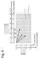
- The gain in coding efficiency achieved by employing an adaptive interpolation filter according to the present invention is illustrated in Fig. 10A and B, which show a comparison of the coding efficiency achieved with fixed filter (JM), with a conventional non-separable adaptive two-dimensional filter and with the separable adaptive filter of the present invention. It can be seen that the coding efficiency achieved with the inventive separable adaptive filter is similar to the coding efficiency achieved with the conventional non-separable filter. Both filtering methods offer significant gains compared to the fixed filter of H.264/AVC.
- However, the separable filter of the present invention further provides a substantial reduction of the computational complexity of the filtering itself, as it is illustrated in Fig. 11. Applying 6x6-tap two-dimensional non-separable filters requires 360 calculations for each coding block with quarter-pel resolution. With the separable 6-taps filter of the present invention, the number of calculations is reduced to 90.
- Summarizing, the present invention relates to a method for determining filter coefficients of a separable two-dimensional adaptive interpolation filter used for motion compensation with sub-pel resolution, a corresponding method for video data compression with adaptive filtering, and a corresponding apparatus. According to the present invention, the two-dimensional interpolation filter is separated into a one-dimensional horizontal interpolation filter and a one-dimensional vertical interpolation filter. Filter coefficients of the first one-dimensional interpolation filter are determined from blocks of video data having motion vectors that indicate a full-pel displacement in the interpolation direction of the second one-dimensional filter. The first one-dimensional filter may then be applied to the video image so as to obtain one-dimensionally interpolated blocks of video data. Filter coefficients of the second one-dimensional interpolation filter are then determined in a second step from interpolated blocks of video data having motion vectors that indicate a sub-pel displacement in the interpolation direction of the second one-dimensional filter. According to this invention, filter coefficients can be determined in a highly efficient manner by solving systems of linear equations.
Claims (19)
- A method for determining filter coefficients of a two-dimensional adaptive interpolation filter for motion compensation of a sequence of video images, said two-dimensional adaptive interpolation filter being separable into a first and a second one-dimensional filter, said first and second one-dimensional filter performing interpolation along a first and a second direction, respectively, said first direction being either one of the horizontal and the vertical direction, said second direction being either one of the horizontal and the vertical direction other than the first direction, said method comprising the steps of
dividing the video images into a plurality of blocks;
determining displacement vectors indicating image displacement between a current block and a previous block, said displacement vectors having a fractional-pel resolution;
determining filter coefficients of the first one-dimensional filter based on blocks having first displacement vectors that indicate a sub-pel displacement in the first direction and a full-pel displacement in the second direction; and
determining filter coefficients of the second one-dimensional filter based on blocks having second displacement vectors other than the first displacement vectors. - A method according to claim 1, wherein the filter coefficients of the second one-dimensional filter are determined based on blocks having displacement vectors that indicate a full-pel displacement in the first direction and a sub-pel displacement in the second direction.
- A method according to claim 1, further comprising the step of
applying the first one-dimensional filter so as to obtain one-dimensionally interpolated blocks of video data,
wherein the filter coefficients of the second one-dimensional filter are determined based on one-dimensionally interpolated blocks having displacement vectors that indicate a sub-pel displacement in the first direction and a sub-pel displacement in the second direction. - A method according to any of claims 1 to 3, wherein filter coefficients are determined by computing a measure indicating accuracy of the motion compensation and by varying values of the filter coefficients so as to optimize the computed measure.
- A method according to any of claims 1 to 3, wherein filter coefficients are determined by solving a system of linear equations so as to determine values of the filter coefficients that optimize accuracy of the motion compensation.
- A method for video data compression, the method comprising the steps of
determining a displacement vector indicating image displacement between a current block of video data and a previous block of video data, said displacement vector having a fractional-pel resolution;
obtaining filter coefficients of a two-dimensional adaptive interpolation filter by performing all steps of a method according to any of claims 1 to 5;
obtaining pixel values at sub-pel positions indicated by the displacement vector by applying the two-dimensional adaptive interpolation filter to the previous block of video data;
obtaining a prediction error signal by applying motion compensation to the current block of video data based on the obtained pixel values and the displacement vector; and
generating compressed video data by encoding the prediction error signal and the filter coefficients. - A method according to claim 6, wherein the step of obtaining pixel values further comprises
a first interpolation step, wherein the first one-dimensional filter is applied to the previous block of video data so as to obtain pixel values that correspond to a one-dimensionally interpolated block of video data; and
a second interpolation step, wherein the second one-dimensional filter is applied to the one-dimensionally interpolated block of video data. - A method according to claim 7, wherein the first interpolation step does not affect a pixel value at a full-pel position.
- A method according to claim 8, wherein the second interpolation step does not affect a pixel value at a full-pel position nor a pixel value obtained by the first interpolation step.
- A method according to any of claims 6 to 9, wherein pixel values at a certain sub-pel position are determined by applying a two-dimensional adaptive interpolation filter that is specific for the certain sub-pel position.
- A method according to claim 10, wherein a two-dimensional adaptive interpolation filter that is specific for a full-pel position in the first direction is determined by filter coefficients of the second one-dimensional filter only.
- A method according to claim 10 or 11, wherein a two-dimensional adaptive interpolation filter that is specific for a full-pel position in the second direction is determined by filter coefficients of the first one-dimensional filter only.
- A method according to any of claims 10 to 12, wherein a two-dimensional adaptive interpolation filter that is specific for a sub-pel position in the first and the second direction comprises filter coefficients of the first and the second one-dimensional filter.
- A method according to any of claims 10 to 13, wherein at least some of the filter coefficients are obtained by exploiting symmetry properties between two different two-dimensional adaptive interpolation filters that are specific for two different sub-pel positions, respectively.
- A method according to any of claims 6 to 14, wherein at least some of the filter coefficients are obtained by exploiting symmetry properties of the two-dimensional adaptive interpolation filter.
- A method according to claim 15, wherein the two-dimensional adaptive interpolation filter is symmetric with respect to at least either one of horizontal and vertical mirroring.
- A method according to any of claims 6 to 16, wherein the step of obtaining filter coefficients is repeated for either one of every slice of video data, every video image, and every sequence of video images.
- An apparatus for encoding video data, said apparatus being adapted to carry out all steps of a method according to any of claims 1 to 17.
- A computer program product comprising a computer readable medium having computer readable program code embodied thereon, the program code being adapted to carry out all steps of a method according to any of claims 1 to 17.
Priority Applications (7)
| Application Number | Priority Date | Filing Date | Title |
|---|---|---|---|
| EP07007994A EP1983759A1 (en) | 2007-04-19 | 2007-04-19 | Estimation of separable adaptive interpolation filters for hybrid video coding |
| US12/596,574 US20100135398A1 (en) | 2007-04-19 | 2008-04-18 | Method for determining filter coefficient of two-dimensional adaptive interpolation filter |
| PCT/JP2008/001034 WO2008132828A1 (en) | 2007-04-19 | 2008-04-18 | Two-dimensional adaptive interpolation filter coefficient decision method |
| CN2008800125283A CN101663898B (en) | 2007-04-19 | 2008-04-18 | Method for Determining Filter Coefficients of Two-Dimensional Adaptive Interpolation Filter |
| JP2009511679A JPWO2008132828A1 (en) | 2007-04-19 | 2008-04-18 | Filter coefficient determination method for two-dimensional adaptive interpolation filter |
| EP08751578A EP2141931A1 (en) | 2007-04-19 | 2008-04-18 | Two-dimensional adaptive interpolation filter coefficient decision method |
| KR1020097021667A KR20100015651A (en) | 2007-04-19 | 2008-04-18 | Two-dimensional adaptive interpolation filter coefficient decision method |
Applications Claiming Priority (1)
| Application Number | Priority Date | Filing Date | Title |
|---|---|---|---|
| EP07007994A EP1983759A1 (en) | 2007-04-19 | 2007-04-19 | Estimation of separable adaptive interpolation filters for hybrid video coding |
Publications (1)
| Publication Number | Publication Date |
|---|---|
| EP1983759A1 true EP1983759A1 (en) | 2008-10-22 |
Family
ID=38512146
Family Applications (2)
| Application Number | Title | Priority Date | Filing Date |
|---|---|---|---|
| EP07007994A Withdrawn EP1983759A1 (en) | 2007-04-19 | 2007-04-19 | Estimation of separable adaptive interpolation filters for hybrid video coding |
| EP08751578A Withdrawn EP2141931A1 (en) | 2007-04-19 | 2008-04-18 | Two-dimensional adaptive interpolation filter coefficient decision method |
Family Applications After (1)
| Application Number | Title | Priority Date | Filing Date |
|---|---|---|---|
| EP08751578A Withdrawn EP2141931A1 (en) | 2007-04-19 | 2008-04-18 | Two-dimensional adaptive interpolation filter coefficient decision method |
Country Status (6)
| Country | Link |
|---|---|
| US (1) | US20100135398A1 (en) |
| EP (2) | EP1983759A1 (en) |
| JP (1) | JPWO2008132828A1 (en) |
| KR (1) | KR20100015651A (en) |
| CN (1) | CN101663898B (en) |
| WO (1) | WO2008132828A1 (en) |
Cited By (9)
| Publication number | Priority date | Publication date | Assignee | Title |
|---|---|---|---|---|
| WO2009044356A3 (en) * | 2007-10-05 | 2009-06-04 | Nokia Corp | Video coding with pixel-aligned directional adaptive interpolation filters |
| WO2009151563A1 (en) * | 2008-06-12 | 2009-12-17 | Thomson Licensing | Methods and apparatus for locally adaptive filtering for motion compensation interpolation and reference picture filtering |
| EP2296380A1 (en) | 2009-09-03 | 2011-03-16 | Panasonic Corporation | Efficient syntax for AIF signalling |
| EP2375744A1 (en) | 2010-04-12 | 2011-10-12 | Panasonic Corporation | Complexity reduction for 1/8-pel interpolation |
| EP2396771A4 (en) * | 2009-02-13 | 2012-12-12 | Research In Motion Ltd | In-loop deblocking for intra-coded images or frames |
| EP2709362A4 (en) * | 2011-06-13 | 2014-09-24 | Nippon Telegraph & Telephone | VIDEO ENCODING DEVICE, VIDEO DECODING DEVICE, VIDEO ENCODING METHOD, VIDEO DECODING METHOD, VIDEO ENCODING PROGRAM, VIDEO DECODING PROGRAM |
| WO2015200835A1 (en) * | 2014-06-26 | 2015-12-30 | Qualcomm Incorporated | Filters for advanced residual prediction in video coding |
| CN113228637A (en) * | 2018-12-17 | 2021-08-06 | 北京字节跳动网络技术有限公司 | Shape dependent interpolation filter |
| EP4029254A4 (en) * | 2019-10-03 | 2022-12-14 | Huawei Technologies Co., Ltd. | ENCODER, DECODER AND RELATED METHODS USING INTERPOLATED FILTERING |
Families Citing this family (34)
| Publication number | Priority date | Publication date | Assignee | Title |
|---|---|---|---|---|
| CN102224734B (en) * | 2008-10-02 | 2013-11-13 | 索尼公司 | Image processing apparatus and method |
| KR101353304B1 (en) * | 2008-10-24 | 2014-01-21 | 에스케이 텔레콤주식회사 | Video Encoding/Decoding Method and Apparatus Using Adaptive Interpolation Filter Coefficient |
| JP2010157949A (en) * | 2009-01-05 | 2010-07-15 | Toshiba Corp | Moving image coding/decoding method and device |
| US20100208804A1 (en) * | 2009-02-13 | 2010-08-19 | Xiang Yu | Modified entropy encoding for images and videos |
| JP5334070B2 (en) * | 2009-02-13 | 2013-11-06 | ブラックベリー リミテッド | Adaptive quantization with balanced pixel region distortion distribution in image processing |
| JP2011050001A (en) * | 2009-08-28 | 2011-03-10 | Sony Corp | Image processing apparatus and method |
| JP2011199396A (en) * | 2010-03-17 | 2011-10-06 | Ntt Docomo Inc | Moving image prediction encoding device, moving image prediction encoding method, moving image prediction encoding program, moving image prediction decoding device, moving image prediction decoding method, and moving image prediction decoding program |
| KR101682147B1 (en) * | 2010-04-05 | 2016-12-05 | 삼성전자주식회사 | Method and apparatus for interpolation based on transform and inverse transform |
| WO2011126759A1 (en) | 2010-04-09 | 2011-10-13 | Sony Corporation | Optimal separable adaptive loop filter |
| MY182191A (en) * | 2010-07-09 | 2021-01-18 | Samsung Electronics Co Ltd | Image interpolation method and apparatus |
| JP5570363B2 (en) * | 2010-09-22 | 2014-08-13 | Kddi株式会社 | Moving picture encoding apparatus, moving picture decoding apparatus, moving picture encoding method, moving picture decoding method, and program |
| JP2012104945A (en) * | 2010-11-08 | 2012-05-31 | Sony Corp | Image processing apparatus, image processing method, and program |
| US10045046B2 (en) | 2010-12-10 | 2018-08-07 | Qualcomm Incorporated | Adaptive support for interpolating values of sub-pixels for video coding |
| US9172972B2 (en) * | 2011-01-05 | 2015-10-27 | Qualcomm Incorporated | Low complexity interpolation filtering with adaptive tap size |
| US9049454B2 (en) * | 2011-01-19 | 2015-06-02 | Google Technology Holdings Llc. | High efficiency low complexity interpolation filters |
| US8964853B2 (en) | 2011-02-23 | 2015-02-24 | Qualcomm Incorporated | Multi-metric filtering |
| US20120230407A1 (en) | 2011-03-11 | 2012-09-13 | General Instrument Corporation | Interpolation Filter Selection Using Prediction Index |
| EP2724534A2 (en) | 2011-06-24 | 2014-04-30 | Motorola Mobility LLC | Selection of phase offsets for interpolation filters for motion compensation |
| JP5649523B2 (en) * | 2011-06-27 | 2015-01-07 | 日本電信電話株式会社 | Video encoding method, apparatus, video decoding method, apparatus, and program thereof |
| CN103650506B (en) | 2011-07-01 | 2017-08-15 | 谷歌技术控股有限责任公司 | Joint sub-pixel interpolation wave filter for time prediction |
| KR20130049523A (en) * | 2011-11-04 | 2013-05-14 | 오수미 | Apparatus for generating intra prediction block |
| MX2014013850A (en) * | 2012-05-14 | 2015-05-08 | Luca Rossato | CODIFICATION AND RECONSTRUCTION OF RESIDUAL DATA BASED ON SUPPORT INFORMATION. |
| IN2015MN00022A (en) | 2012-07-26 | 2015-10-16 | Olive Medical Corp | |
| IN2015MN00018A (en) | 2012-07-26 | 2015-10-16 | Olive Medical Corp | |
| AU2014233515B2 (en) * | 2013-03-15 | 2018-11-01 | DePuy Synthes Products, Inc. | Super resolution and color motion artifact correction in a pulsed color imaging system |
| WO2014145249A1 (en) | 2013-03-15 | 2014-09-18 | Olive Medical Corporation | Controlling the integral light energy of a laser pulse |
| EP2967301B1 (en) | 2013-03-15 | 2021-11-03 | DePuy Synthes Products, Inc. | Scope sensing in a light controlled environment |
| AU2015230978B2 (en) | 2014-03-21 | 2020-01-23 | DePuy Synthes Products, Inc. | Card edge connector for an imaging sensor |
| US11122262B2 (en) | 2014-06-27 | 2021-09-14 | Samsung Electronics Co., Ltd. | System and method for motion compensation in video coding |
| CA2959023C (en) * | 2014-08-22 | 2023-01-10 | Nova Southeastern University | Data adaptive compression and data encryption using kronecker products |
| CN105791865B (en) * | 2014-12-22 | 2020-01-17 | 江苏省电力公司南京供电公司 | Intra-frame prediction and deblocking filtering method |
| US10009622B1 (en) | 2015-12-15 | 2018-06-26 | Google Llc | Video coding with degradation of residuals |
| MX2020001665A (en) * | 2017-09-13 | 2020-03-20 | Samsung Electronics Co Ltd | Apparatus and method for encoding motion vector by using basic motion vector, and decoding apparatus and method. |
| MX2021012760A (en) | 2019-04-19 | 2022-01-25 | Huawei Tech Co Ltd | METHOD AND APPARATUS FOR DERIVING AN INTERPOLATION FILTER INDEX FOR A CURRENT BLOCK. |
Citations (1)
| Publication number | Priority date | Publication date | Assignee | Title |
|---|---|---|---|---|
| WO2004006558A2 (en) * | 2002-07-09 | 2004-01-15 | Nokia Corporation | Method and system for selecting interpolation filter type in video coding |
Family Cites Families (6)
| Publication number | Priority date | Publication date | Assignee | Title |
|---|---|---|---|---|
| JP4102973B2 (en) * | 2002-04-24 | 2008-06-18 | 日本電気株式会社 | Encoding method and decoding method of moving image, apparatus and program using the same |
| US20040076333A1 (en) * | 2002-10-22 | 2004-04-22 | Huipin Zhang | Adaptive interpolation filter system for motion compensated predictive video coding |
| CN1216495C (en) * | 2003-09-27 | 2005-08-24 | 浙江大学 | Video image sub-picture-element interpolation method and device |
| CN1256849C (en) * | 2003-11-04 | 2006-05-17 | 浙江大学 | Method and device for 1/4 pixel precision interpolation |
| EP1886502A2 (en) * | 2005-04-13 | 2008-02-13 | Universität Hannover | Method and apparatus for enhanced video coding |
| US8208564B2 (en) * | 2005-06-24 | 2012-06-26 | Ntt Docomo, Inc. | Method and apparatus for video encoding and decoding using adaptive interpolation |
-
2007
- 2007-04-19 EP EP07007994A patent/EP1983759A1/en not_active Withdrawn
-
2008
- 2008-04-18 JP JP2009511679A patent/JPWO2008132828A1/en not_active Withdrawn
- 2008-04-18 CN CN2008800125283A patent/CN101663898B/en not_active Expired - Fee Related
- 2008-04-18 US US12/596,574 patent/US20100135398A1/en not_active Abandoned
- 2008-04-18 KR KR1020097021667A patent/KR20100015651A/en not_active Withdrawn
- 2008-04-18 WO PCT/JP2008/001034 patent/WO2008132828A1/en not_active Ceased
- 2008-04-18 EP EP08751578A patent/EP2141931A1/en not_active Withdrawn
Patent Citations (1)
| Publication number | Priority date | Publication date | Assignee | Title |
|---|---|---|---|---|
| WO2004006558A2 (en) * | 2002-07-09 | 2004-01-15 | Nokia Corporation | Method and system for selecting interpolation filter type in video coding |
Non-Patent Citations (12)
| Title |
|---|
| CHONO,KEI-ICHI AND MIYAMOTO, YOSHIHIRO: "Modified Adaptive Interpolation Filter", JOINT VIDEO TEAM (JVT) OF ISO/MPEG & ITU-T VCEG, JVT-D078, 22 July 2002 (2002-07-22) - 26 July 2002 (2002-07-26), Klagenfurt, Austria, pages 1 - 27, XP030005352 * |
| KIMATA H ET AL: "3D ADAPTIVE MOTION VECTOR CODING INTEGRATED WITH BLOCK-BASED ADAPTIVE INTERPOLATION FILTER", SYSTEMS & COMPUTERS IN JAPAN, WILEY, HOBOKEN, NJ, US, vol. 35, no. 14, December 2004 (2004-12-01), pages 10 - 20, XP001211995, ISSN: 0882-1666 * |
| OLIVER WERNER: "Driftanalyse und Driftreduktion für hierarchische Bewegtbildcodierungen, Abschnitte 4. - 4.3 und 5.4", December 1996, UNIVERSITÄT HANNOVER, FAKULTÄT FÜR MASCHINENWESEN, GERMANY, HANNOVER, GERMANY, XP002454502 * |
| POLIN LAI ET AL: "Adaptive filtering for video coding with focus change", 2007 IEEE INTERNATIONAL CONFERENCE ON ACOUSTICS, SPEECH, AND SIGNAL PROCESSING (IEEE CAT. NO. 07CH37846) IEEE PISCATAWAY, NJ, USA, 15 April 2007 (2007-04-15), pages I - 661, XP002454496, ISBN: 1-4244-0727-3 * |
| RUSANOVSKYY, D. AND UGUR, K.: "Spatio-Temporal Adaptation of Interpolation Filter for Low Complexity Decoding", ITU TELECOMMUNICATIONS STANDARDIZATION SECTOR VCEG-AE22, 15 January 2007 (2007-01-15) - 16 January 2007 (2007-01-16), Marrakech, MA, pages 1 - 10, XP002454499 * |
| UGUR K ET AL: "Adaptive interpolation filter with flexible symmetry for coding high resolution high quality video", 2007 IEEE INTERNATIONAL CONFERENCE ON ACOUSTICS, SPEECH, AND SIGNAL PROCESSING (IEEE CAT. NO. 07CH37846) IEEE PISCATAWAY, NJ, USA, 15 April 2007 (2007-04-15), pages I - 1013, XP002454498, ISBN: 1-4244-0727-3 * |
| VATIS Y ET AL: "Locally adaptive non-separable interpolation filter for H.264/AVC", 2006 INTERNATIONAL CONFERENCE ON IMAGE PROCESSING IEEE PISCATAWAY, NJ, USA, 1996, pages 4 pp., XP002454497, ISBN: 1-4244-0481-9 * |
| VATIS Y ET AL: "Motion-And Aliasing-Compensated Prediction Using a Two-Dimensional Non-Separable Adaptive Wiener Interpolation Filter", IMAGE PROCESSING, 2005. ICIP 2005. IEEE INTERNATIONAL CONFERENCE ON GENOVA, ITALY 11-14 SEPT. 2005, PISCATAWAY, NJ, USA,IEEE, 11 September 2005 (2005-09-11), pages 894 - 897, XP010851198, ISBN: 0-7803-9134-9 * |
| WEDI T ET AL: "Motion- and aliasing-compensated prediction for hybrid video coding", IEEE TRANSACTIONS ON CIRCUITS AND SYSTEMS FOR VIDEO TECHNOLOGY, IEEE SERVICE CENTER, PISCATAWAY, NJ, US, vol. 13, no. 7, July 2003 (2003-07-01), pages 577 - 586, XP011099250, ISSN: 1051-8215 * |
| WEDI T: "ADAPTIVE INTERPOLATION FILTER FOR MOTION AND ALIASING COMPENSATED PREDICTION", PROCEEDINGS OF THE SPIE, SPIE, BELLINGHAM, VA, US, vol. 4671, 21 January 2002 (2002-01-21), pages 415 - 422, XP008014091, ISSN: 0277-786X * |
| WEDI, THOMAS: "Advanced motion compensated prediction methods", ITU TELECOMMUNICATIONS STANDARDIZATION SECTOR, VCEG-X10, 18 October 2003 (2003-10-18) - 22 October 2003 (2003-10-22), Palma de Mallorca,Spain, pages 1 - 8, XP002454495 * |
| WERNER O: "Drift analysis and drift reduction for multiresolution hybrid video coding", SIGNAL PROCESSING. IMAGE COMMUNICATION, ELSEVIER SCIENCE PUBLISHERS, AMSTERDAM, NL, vol. 8, no. 5, July 1996 (1996-07-01), pages 387 - 409, XP004047049, ISSN: 0923-5965 * |
Cited By (13)
| Publication number | Priority date | Publication date | Assignee | Title |
|---|---|---|---|---|
| WO2009044356A3 (en) * | 2007-10-05 | 2009-06-04 | Nokia Corp | Video coding with pixel-aligned directional adaptive interpolation filters |
| WO2009151563A1 (en) * | 2008-06-12 | 2009-12-17 | Thomson Licensing | Methods and apparatus for locally adaptive filtering for motion compensation interpolation and reference picture filtering |
| EP2396771A4 (en) * | 2009-02-13 | 2012-12-12 | Research In Motion Ltd | In-loop deblocking for intra-coded images or frames |
| EP2296380A1 (en) | 2009-09-03 | 2011-03-16 | Panasonic Corporation | Efficient syntax for AIF signalling |
| EP2375744A1 (en) | 2010-04-12 | 2011-10-12 | Panasonic Corporation | Complexity reduction for 1/8-pel interpolation |
| WO2011128023A1 (en) | 2010-04-12 | 2011-10-20 | Panasonic Corporation | Complexity reduction for 1/8-pel interpolation |
| EP2709362A4 (en) * | 2011-06-13 | 2014-09-24 | Nippon Telegraph & Telephone | VIDEO ENCODING DEVICE, VIDEO DECODING DEVICE, VIDEO ENCODING METHOD, VIDEO DECODING METHOD, VIDEO ENCODING PROGRAM, VIDEO DECODING PROGRAM |
| WO2015200835A1 (en) * | 2014-06-26 | 2015-12-30 | Qualcomm Incorporated | Filters for advanced residual prediction in video coding |
| US20150382009A1 (en) * | 2014-06-26 | 2015-12-31 | Qualcomm Incorporated | Filters for advanced residual prediction in video coding |
| US9924191B2 (en) * | 2014-06-26 | 2018-03-20 | Qualcomm Incorporated | Filters for advanced residual prediction in video coding |
| CN113228637A (en) * | 2018-12-17 | 2021-08-06 | 北京字节跳动网络技术有限公司 | Shape dependent interpolation filter |
| EP4029254A4 (en) * | 2019-10-03 | 2022-12-14 | Huawei Technologies Co., Ltd. | ENCODER, DECODER AND RELATED METHODS USING INTERPOLATED FILTERING |
| US12041230B2 (en) | 2019-10-03 | 2024-07-16 | Huawei Technologies Co., Ltd. | Encoder, decoder and corresponding methods using interpolation filtering |
Also Published As
| Publication number | Publication date |
|---|---|
| WO2008132828A1 (en) | 2008-11-06 |
| US20100135398A1 (en) | 2010-06-03 |
| EP2141931A1 (en) | 2010-01-06 |
| KR20100015651A (en) | 2010-02-12 |
| CN101663898A (en) | 2010-03-03 |
| CN101663898B (en) | 2011-11-09 |
| JPWO2008132828A1 (en) | 2010-07-22 |
Similar Documents
| Publication | Publication Date | Title |
|---|---|---|
| EP1983759A1 (en) | Estimation of separable adaptive interpolation filters for hybrid video coding | |
| KR100813963B1 (en) | Lossless encoding and decoding method for video | |
| US8553768B2 (en) | Image encoding/decoding method and apparatus | |
| EP2157799A1 (en) | Interpolation filter with local adaptation based on block edges in the reference frame | |
| EP2048886A1 (en) | Coding of adaptive interpolation filter coefficients | |
| EP2141927A1 (en) | Filters for video coding | |
| EP0644697A2 (en) | Method for half-pixel motion compensation in image decoding | |
| EP1359764A2 (en) | Video encoding method with fading compensation | |
| KR20020095013A (en) | Image predictive coding method | |
| KR20040047977A (en) | Spatial scalable compression | |
| EP1359765A2 (en) | Fading estimation/compensation in video encoding | |
| KR20040106364A (en) | System and method for providing single-layer video encoded bitstreams suitable for reduced-complexity decoding | |
| KR101375667B1 (en) | Method and apparatus for Video encoding and decoding | |
| KR100541623B1 (en) | Prediction method and device with motion compensation | |
| KR19980017213A (en) | Image Decoding System with Compensation Function for Degraded Image | |
| US5790207A (en) | Motion compensation method for use in an image encoding system | |
| US20160029043A1 (en) | Methods and Systems for Noncausal Predictive Image and Video Coding | |
| KR101462959B1 (en) | Method and apparatus for video encoding and decoding using extended block filtering | |
| EP1841235A1 (en) | Video compression by adaptive 2D transformation in spatial and temporal direction | |
| KR101562343B1 (en) | Method and apparatus for image interpolation having quarter pixel accuracy using intra prediction modes | |
| KR102111437B1 (en) | Method and apparatus for image interpolation having quarter pixel accuracy using intra prediction modes | |
| KR0134496B1 (en) | Mpeg coder using adaptive scan method | |
| KR101934840B1 (en) | Method and apparatus for image interpolation having quarter pixel accuracy using intra prediction modes | |
| KR101810198B1 (en) | Method and apparatus for image interpolation having quarter pixel accuracy using intra prediction modes | |
| KR101700411B1 (en) | Method and apparatus for image interpolation having quarter pixel accuracy using intra prediction modes |
Legal Events
| Date | Code | Title | Description |
|---|---|---|---|
| PUAI | Public reference made under article 153(3) epc to a published international application that has entered the european phase |
Free format text: ORIGINAL CODE: 0009012 |
|
| AK | Designated contracting states |
Kind code of ref document: A1 Designated state(s): AT BE BG CH CY CZ DE DK EE ES FI FR GB GR HU IE IS IT LI LT LU LV MC MT NL PL PT RO SE SI SK TR |
|
| AX | Request for extension of the european patent |
Extension state: AL BA HR MK RS |
|
| RAP1 | Party data changed (applicant data changed or rights of an application transferred) |
Owner name: PANASONIC CORPORATION |
|
| AKX | Designation fees paid | ||
| STAA | Information on the status of an ep patent application or granted ep patent |
Free format text: STATUS: THE APPLICATION IS DEEMED TO BE WITHDRAWN |
|
| 18D | Application deemed to be withdrawn |
Effective date: 20090423 |
|
| REG | Reference to a national code |
Ref country code: DE Ref legal event code: 8566 |