EP1983423A2 - Printing system, print data creation apparatus and computer-readable control program for the print data creation apparatus - Google Patents
Printing system, print data creation apparatus and computer-readable control program for the print data creation apparatus Download PDFInfo
- Publication number
- EP1983423A2 EP1983423A2 EP08007469A EP08007469A EP1983423A2 EP 1983423 A2 EP1983423 A2 EP 1983423A2 EP 08007469 A EP08007469 A EP 08007469A EP 08007469 A EP08007469 A EP 08007469A EP 1983423 A2 EP1983423 A2 EP 1983423A2
- Authority
- EP
- European Patent Office
- Prior art keywords
- printer
- setting
- print data
- update information
- data creation
- Prior art date
- Legal status (The legal status is an assumption and is not a legal conclusion. Google has not performed a legal analysis and makes no representation as to the accuracy of the status listed.)
- Withdrawn
Links
Images










Classifications
-
- G—PHYSICS
- G06—COMPUTING OR CALCULATING; COUNTING
- G06F—ELECTRIC DIGITAL DATA PROCESSING
- G06F3/00—Input arrangements for transferring data to be processed into a form capable of being handled by the computer; Output arrangements for transferring data from processing unit to output unit, e.g. interface arrangements
- G06F3/12—Digital output to print unit, e.g. line printer, chain printer
- G06F3/1201—Dedicated interfaces to print systems
- G06F3/1223—Dedicated interfaces to print systems specifically adapted to use a particular technique
- G06F3/1229—Printer resources management or printer maintenance, e.g. device status, power levels
- G06F3/123—Software or firmware update, e.g. device firmware management
-
- B—PERFORMING OPERATIONS; TRANSPORTING
- B41—PRINTING; LINING MACHINES; TYPEWRITERS; STAMPS
- B41J—TYPEWRITERS; SELECTIVE PRINTING MECHANISMS, i.e. MECHANISMS PRINTING OTHERWISE THAN FROM A FORME; CORRECTION OF TYPOGRAPHICAL ERRORS
- B41J11/00—Devices or arrangements of selective printing mechanisms, e.g. ink-jet printers or thermal printers, for supporting or handling copy material in sheet or web form
- B41J11/0025—Handling copy materials differing in width
- B41J11/003—Paper-size detection, i.e. automatic detection of the length and/or width of copy material
-
- B—PERFORMING OPERATIONS; TRANSPORTING
- B41—PRINTING; LINING MACHINES; TYPEWRITERS; STAMPS
- B41J—TYPEWRITERS; SELECTIVE PRINTING MECHANISMS, i.e. MECHANISMS PRINTING OTHERWISE THAN FROM A FORME; CORRECTION OF TYPOGRAPHICAL ERRORS
- B41J11/00—Devices or arrangements of selective printing mechanisms, e.g. ink-jet printers or thermal printers, for supporting or handling copy material in sheet or web form
- B41J11/009—Detecting type of paper, e.g. by automatic reading of a code that is printed on a paper package or on a paper roll or by sensing the grade of translucency of the paper
-
- B—PERFORMING OPERATIONS; TRANSPORTING
- B41—PRINTING; LINING MACHINES; TYPEWRITERS; STAMPS
- B41J—TYPEWRITERS; SELECTIVE PRINTING MECHANISMS, i.e. MECHANISMS PRINTING OTHERWISE THAN FROM A FORME; CORRECTION OF TYPOGRAPHICAL ERRORS
- B41J11/00—Devices or arrangements of selective printing mechanisms, e.g. ink-jet printers or thermal printers, for supporting or handling copy material in sheet or web form
- B41J11/0095—Detecting means for copy material, e.g. for detecting or sensing presence of copy material or its leading or trailing end
-
- B—PERFORMING OPERATIONS; TRANSPORTING
- B41—PRINTING; LINING MACHINES; TYPEWRITERS; STAMPS
- B41J—TYPEWRITERS; SELECTIVE PRINTING MECHANISMS, i.e. MECHANISMS PRINTING OTHERWISE THAN FROM A FORME; CORRECTION OF TYPOGRAPHICAL ERRORS
- B41J15/00—Devices or arrangements of selective printing mechanisms, e.g. ink-jet printers or thermal printers, specially adapted for supporting or handling copy material in continuous form, e.g. webs
- B41J15/04—Supporting, feeding, or guiding devices; Mountings for web rolls or spindles
- B41J15/042—Supporting, feeding, or guiding devices; Mountings for web rolls or spindles for loading rolled-up continuous copy material into printers, e.g. for replacing a used-up paper roll; Point-of-sale printers with openable casings allowing access to the rolled-up continuous copy material
-
- B—PERFORMING OPERATIONS; TRANSPORTING
- B41—PRINTING; LINING MACHINES; TYPEWRITERS; STAMPS
- B41J—TYPEWRITERS; SELECTIVE PRINTING MECHANISMS, i.e. MECHANISMS PRINTING OTHERWISE THAN FROM A FORME; CORRECTION OF TYPOGRAPHICAL ERRORS
- B41J3/00—Typewriters or selective printing or marking mechanisms characterised by the purpose for which they are constructed
- B41J3/407—Typewriters or selective printing or marking mechanisms characterised by the purpose for which they are constructed for marking on special material
- B41J3/4075—Tape printers; Label printers
-
- G—PHYSICS
- G06—COMPUTING OR CALCULATING; COUNTING
- G06F—ELECTRIC DIGITAL DATA PROCESSING
- G06F3/00—Input arrangements for transferring data to be processed into a form capable of being handled by the computer; Output arrangements for transferring data from processing unit to output unit, e.g. interface arrangements
- G06F3/12—Digital output to print unit, e.g. line printer, chain printer
- G06F3/1201—Dedicated interfaces to print systems
- G06F3/1202—Dedicated interfaces to print systems specifically adapted to achieve a particular effect
- G06F3/1203—Improving or facilitating administration, e.g. print management
- G06F3/1204—Improving or facilitating administration, e.g. print management resulting in reduced user or operator actions, e.g. presetting, automatic actions, using hardware token storing data
Definitions
- the present disclosure relates generally to technical fields including a printing system, a print data creation apparatus, and a computer program. More specifically, it relates to a printing system that can simultaneously change a printer setting file in a print data creation apparatus and update firmware of a printer connected to this print data creation apparatus, the print data creation apparatus, and a computer-readable control program for the print data creation apparatus.
- a printing system that prints with a printing apparatus connected to a print data creation apparatus such as a personal computer.
- a unit detection switch is provided to a roll paper unit set position in the printing apparatus. If a value indicated by a signal detected by the unit detection switch is not stored in a medium information storage area, it is determined that the set roll paper unit is of a new type. Then, missing information about the new type of roll paper unit (medium) is transmitted to the personal computer.
- the printing apparatus receives the medium information about the new type of roll paper unit from the personal computer, medium information acquisition processing will be carried out. In the medium information acquisition processing, the received medium information is stored in the medium information storage area and the firmware of the printing apparatus is updated (see, for example, Japanese Patent Application Laid Open Publication No. 2005-258858 ).
- the printing apparatus determines that the information about a new print medium is needed, the information of the print medium is acquired from the print data creation apparatus, so that the firmware of the printing apparatus can be updated.
- this method will only update the firmware of the printing apparatus, and the information of a printer driver of the print data creation apparatus is not updated. Therefore, this problem has suffered a problem that the information of the printer driver of the print data creation apparatus does not match the print medium.
- a print data creation apparatus as claimed in claim 1.
- the apparatus is connectable to a printer for printing on a print medium to create print data to be printed by the printer, the print data creation apparatus comprising: a display device that displays a variety of information, a setting alteration screen display control device that displays a setting alteration screen which is used to change settings of the printer on the display device, a setting file storage device that store a setting file including setting information to be referred by a printer driver of the printer, a setting file alteration device that changes contents of the setting file stored in the setting file storage device based on the settings of the printer changed on the setting alteration screen, an update information creation device that creates update information which updates firmware of the printer in response to a change in the setting file brought about by the setting file alteration device, and an update information transmission device that transmits the update information created by the update information creation device to the printer.
- a computer-readable control program for a print data creation apparatus connectable to a printer for printing on a print medium to create print data to be printed by the printer, as claimed in claim 7.
- the control program comprises setting alteration screen display control instructions for displaying a setting alteration screen which is used to change settings of the printer, setting file alteration instructions for changing contents of the setting file including setting information which is referred to by a printer driver of the printer based on the settings of the printer changed on the setting alteration screen, update information creation instructions for creating update information which updates firmware of the printer in response to a change in the setting file brought about by the setting file alteration instructions, and update information transmission instructions for transmitting the update information created by the update information creation instructions to the printer.
- a printing system as claimed in claim 13.
- the system comprises a printing data creation apparatus and a printer that prints the print data on a print medium, the printer including an update information reception device that receives the update information transmitted by the update information transmission device, and a firmware update device that updates the firmware of the printer based on the update information received by the update information reception device.
- a method to control a print data creation apparatus as claimed in claim 14.
- the printing system 1 consists of a printer 3 and a known personal computer 2 connected to each other with a cable 18.
- the printer 3 contains a roll paper holder 67 and prints on a die-cut label 72 stuck to a tape 71 wound around the roll paper holder 67.
- a cover 5 is axially supported in such a manner that it can swing around.
- the lower-part chassis 4 under the cover 5 is equipped with a roll paper holder housing section 12 that houses the roll paper holder 67 around which the tape 71 is wound.
- roll paper holder support sections 6 and 7 are erected respectively which support the roll paper holder 67.
- a roller 8 is mounted which guides the tape 71 as it is pulled out of the roll paper holder 67.
- a print mechanism section 11 is mounted which including a thermal head type print mechanism (not shown). Additionally, at the lower part of the print mechanism section 11, a roll paper discharge outlet 9 is formed that discharges the tape 71 which has printed information on it. Moreover, at the right end of the front face of the lower-part chassis 4, an indication lamp 10 is provided.
- a sensor cover 15 is mounted on the right of the roll paper holder housing section 12 with a screw in an attachable-and-detachable manner.
- a determining concave portion 14 is provided under the sensor cover 15 as shown in FIG. 6 where the sensor cover 15 is detached.
- the sheet determination sensors SS1-SS5 are constituted of a micro push button switch or the like each and used to determine the type of various kinds of sheets, the material of a thermo-sensitive sheet, the width of a roll tape, and the like.
- the sheet determination sensors SS1-SS5 are each a known mechanical switch consisted of a plunger, a micro-switch, etc. The upper end of each of the plungers is equipped so that it protrudes from the bottom of the determining concave portion 14.
- the sheet determination sensors SS1-SS5 detect the existence of sensor holes 60A-60E respectively (see FIG. 4 ) which are formed in a sheet determination section 60 of a DK roll 69. Then, based on ON/OFF signals provided from those sheet determination sensors SS1-SS5 in a control section 40 (see FIG. 7 ) described below, the type of a tape loaded to the DK roll 69, the width (LW) and the length (LL) of a die-cut label, the material of a thermo-sensitive sheet, etc. are identified respectively.
- the plungers of the sheet determination sensors SS1-SS5 protrude from the bottom of the determining concave portion 14 at all times, to provide the OFF state of the micro-switches. That is, if any one of the sensor holes 60A-60E in the sheet determination section 60 faces to the corresponding one of the sheet determination sensors SS1-SS5, its plunger is in an un-pressed state. Therefore, its micro-switch is turned OFF and the corresponding one of the sheet determination sensors SS1-SS5 outputs the OFF signal.
- any one of the sensor holes 60A-60E in the sheet determination section 60 does not face to the corresponding one of the sheet determination sensors SS1-SS5, its plungers is pressed. Therefore, its micro-switch is turned ON and the corresponding one of the sheet determination sensors SS1-SS5 outputs the ON signal.
- the sheet determination sensors SS1-SS5 will output a five-bit signal composed of "0" and "1". If the sheet determination sensors SS1-SS5 are all in the OFF state, that is, if the roll paper holder 67 is not loaded, the five-bit signal of "00000" will be output.
- the plungers of the sheet determination sensors SS1-SS5 are all pressed always, to provide the ON state of the micro-switches.
- the ON signal is output from all of the sheet determination sensors SS1-SS5. That is, when the sensor cover 15 is attached, the five-bit signal of "11111" will be output.
- the print mechanism section 11 includes a thermal head 13 and a platen roller (not shown).
- the tape 71 is transferred in a condition where it is sandwiched between the thermal head 13 and the platen roller.
- a desired image is printed on a predetermined region of the surface of the die-cut label 72 on the tape 71.
- the roll paper holders 67 are roughly split into two types based on whether they have the later-described sheet determination section 60.
- the roll paper holder 67 shown in FIG. 3 is of a type of holding a DT roll 68 which does not have a sheet determination section 60.
- a roll paper unit 70 is constituted by winding the tape 71 around a hollow core.
- the roll paper unit 70 is sandwiched between a first sandwich member 31 and a second sandwich member 32.
- a roll shaft 73 is fixed to the second sandwich member 32.
- a fitting section 33 is formed to which the tip of the roll shaft 73 is fitted in an attachable and detachable manner, to sandwich the roll paper unit 70 between the first sandwich member 31 and the second sandwich member 32 so that they may be united in constitution.
- a square pole-shaped convex portion 34 is formed which is held in a condition where it is inserted into a gap between roll paper holder support sections 6.
- a square pole-shaped convex portion (not shown) is formed which is held in a condition where it is inserted into a gap between roll paper holder support sections 7. Since the first sandwich member 31 and the second sandwich member 32 are constituted to be attachable and detachable, the roll paper unit 70 can be replaced.
- the roll paper holder 67 shown in FIG. 4 is of a type of holding the DK roll 69 having the later-described sheet determination section 60.
- a second sandwich member 35 has the sheet determination section 60 at its tip (lower end in a condition where it is loaded in the roll paper holder housing section 12).
- the sensor holes 60A-60E are formed which represent the type of the roll paper holder 67.
- the DK roll 69 has such a configuration that the first sandwich member 31 is fixed to the roll shaft 73 and so the roll paper unit 70 cannot be replaced.
- the DK roll 69 is used as loaded in the roll paper holder housing section 12 in a condition where the sensor cover 15 is detached from the roll paper holder housing section 12.
- the DK roll 68 is used as loaded in the roll paper holder housing section 12 in a condition where the sensor cover 15 is attached to the roll paper holder housing section 12.
- the printer 3 is equipped with a control section 40 that conducts control over it.
- the control section 40 includes a CPU 52 that controls the devices of the printer 3 and an input/output interface 50, a ROM 55, and a RAM 56 that are connected to the CPU 52 via a data bus 51.
- the drive circuit 48 drives the thermal head 13.
- the drive circuit 42 drives a tape cutter drive motor 41 that operates a tape cutter 17.
- the drive circuit 49 drives a tape feed motor 47.
- the USB port 25 connects with the personal computer 2. Further, a USB cable is connected to the USB port 25 and then to the personal computer 2.
- print drive control program executes reading the data from a print data storage area 561 (see FIG. 8 ) in the RAM 56, to drive the thermal head 13 and the tape feed motor 47.
- the parameter table is used to determine a duty ratio for determining the amount of print energy with which to drive the thermal head 13.
- the RAM 56 stores print data and the like transmitted from the personal computer 2.
- a power supply section 57 supplies power in a condition where it is connected to the drive circuits 42, 48, and 49, the sheet determination sensors SS1-SS5, and the control section 40.
- the RAM 56 has the print data storage area 561, a reception medium information storage area 562, a program execution-time information storage area 563 and the like.
- the print data storage area 561 stores print data.
- the reception medium information storage area 562 stores medium information transmitted from the personal computer 2.
- the program execution-time information storage area 563 stores temporary data which occurs during the execution of a program.
- the RAM 56 further has various storage areas besides those illustrated.
- the personal computer 2 of the print data creation apparatus will be described below with reference to FIGS. 1 and 9 .
- the personal computer 2 is equipped in its chassis 200 with a CPU 210 that controls the personal computer 2.
- a CPU 210 that controls the personal computer 2.
- a ROM 220 To the CPU 210 are connected a ROM 220, a RAM 230, a CD-ROM drive 240, and an HDD 250 via a bus 290.
- programs such as the BIOS which are executed by the CPU 210 are stored.
- the RAM 230 stores data temporarily.
- the CD-ROM drive 240 is used to read data from a CD-ROM 241, which is a storage medium of the data inserted into the CD-ROM drive 240.
- the HDD 250 is a data storage device.
- USB registered trademark
- the USB interface 260 is used to establish communication with an external device including the printer 3.
- the display control section 270 performs screen display processing for a monitor 271, on which an operation display screen appears.
- the keyboard 281 and the mouse 282 are used by the user for inputting operations.
- the personal computer 2 may be equipped with a floppy (registered trademark) disk drive, a section to input and output voices etc., a variety of interfaces, etc.
- the CD-ROM 241 stores a print data creation program, settings and data to be used when executing this program, etc.
- the contents of the CD-ROM 241 will be stored into a program storage area 251 (see FIG. 9 ) and a program-related information storage area 252 (see FIG. 9 ) which are arranged in the HDD 250.
- the method for acquiring the print data creation program for the personal computer 2 and data and the like which are used by this program is not limited to the CD-ROM 241 but it may be any other recording medium such as a floppy (registered trademark) disk and an MO (Magneto Optic Disc). Further, those program and data may be acquired from any other terminal on a network by connecting the personal computer 2 to the network.
- the HDD 250 has the program storage area 251, the program-related information storage area 252, a setting file storage area 253, and the like.
- the program storage area 251 stores the print data creation program and other various programs which are executed by the personal computer 2.
- the program-related information storage area 252 stores information such as settings, initial values, data, and the like which are necessary in executing the program.
- the setting file storage area 253 stores setting information about a medium loaded in the roll paper holder 67.
- the HDD 250 further has various storage areas besides those illustrated.
- the RAM 230 has a print data storage area 231, an additional medium information storage area 232, a program execution-time information storage area 233, and the like.
- the print data storage area 231 stores print data.
- the additional medium information storage area 232 stores medium information to be added to the printer 3.
- the program execution-time information storage area 233 stores temporary data which is used during the execution of the program.
- the RAM 230 further has various storage areas besides those illustrated.
- the setting file storage area 253 in the HDD 250 of the personal computer 2 has a name field, a tape type field, a label width field, a label length field, a mount portion width field, an inter-label distance field, a width-directional margin field, a length-directional margin field, and the like.
- the name field stores the name of the roll paper holder 67.
- the tape type field stores the type of tapes (which identifies the shape and the material of long tapes, die-cut labels, and the like).
- the label width field stores the width of the die-cut label 72 loaded in the roll paper holder 67.
- the label length field stores the length of the die-cut label 72 loaded in the roll paper holder 67. Further, the mount portion width field stores the length of a tape width-directional margin of the tape 71 loaded in the roll paper unit 70 except for the die-cut label 72.
- the inter-label distance field stores a distance between the die-cut labels 72 on the tape 71 loaded in the roll paper holder 67.
- the width-directional margin field stores the length of a width-directional margin on the die-cut label 72.
- the length-directional margin field stores the length of a length-directional margin on the die-cut label 72.
- printer setting alteration processing for the personal computer 2 will be described below with reference to FIGS. 12-17 .
- a custom label tool screen 100 such as shown in FIG. 12 will appear on the screen of the monitor 271 of the personal computer 2.
- the DT roll 68 is capable of loading any tape therein.
- the custom label tool is used to accommodate a variety of tapes by accomplishing matching between the printer drive of the personal computer 2 and the firmware of the printer 3.
- the custom label tool screen 100 has on it a name entry field, a printer sheet type field, a label width entry field 107, a label length entry field 108, a mount portion width field, an inter-label distance field, a width-directional margin field 109, and a length-directional margin field as well as an import button, an initial value button, a new button, a deletion button, a high-degree setting button, a registration button, an export button, a cancel button, and the like. Further, the custom label screen 100 will show on it the size of a label that corresponds to a value entered in each of the fields.
- the name field is used to enter, as one example, the name of a printer sheet in the roll paper holder 67, which name can be entered in a text composed of one through 31 one-byte characters or one through 15 two-byte characters.
- the printer sheet type field is capable of selecting a long tape or a die-cut label in it. Corresponding to what is selected in this printer sheet type field, the picture of a printer sheet that appears on the screen will be changed. If the long tape is selected, none of the label length entry field 108 and the inter-label distance field will be displayed out of the label width entry field 107, the label length entry field 108, the mount portion width field, the inter-label distance field, the width-directional margin field 109, and the length-directional margin field.
- one example of a range in which a numeral can be entered in the label width entry field 107 is 12-102mm and one example of a range in which a numeral can be entered in the label length entry field 108 is 25-255mm. It should be noted that if the product is bound for the USA, one example of the range in which a numeral can be entered in the label width entry field 107 is 0.47-4.02 inches and one example of the range in which a numeral can be entered into the label length entry field 108 is 0.98-10.04 inches. It should be noted that the value of the width of the mount portion is displayed on the screen but no numeral can be entered as the value of the width.
- the total label width may come in any one of the seven values of 19, 32, 42, 54, 66, 80.2, and 105. 6; however, the practical effective label width is determined by the equation of "total label width-2x2" (mm). If a label width value is entered into the label width entry field 107, a minimum total label width value out of those seven label width values will be selected which is not smaller than "the entered label width+2x2" (mm). Then, the "(total label width-label width)/2" will be the width of the mount portion. The inter-label distance is displayed on the screen but no numeral can be entered as the value of the distance because its width is fixed to 6mm. It should be noted that if a numeral is entered or changed as the value of the label width or length, the value will also be updated in conjunction with it at the left side on the screen.
- a length of the label's width-directional margin is entered into the width-directional margin field 109.
- the default value of the length of this margin is a width-directional value of 1.5mm.
- the value will take on the numeral of width-directional (0 through label width/2-0.1) and given in units of 0.1mm.
- the value will take on the numeral of width-directional (0 through label width/2-0.01) and given in units of 0.01 inch.
- the value of the length-directional margin is displayed on the screen but no numeral can be entered as the value of the length-directional margin.
- the length-directional margin will take on a value of 3mm if the label length is equal to or less than 100mm and the value of "label lengthx0.03" (mm) if the label length is greater than 100mm.
- FIG. 13 shows the anterior half
- FIG. 14 shows the posterior half of the flowchart of the main routine.
- a name is entered into the name entry field on the custom label tool screen 100 (YES at S10). If the name exists already in the name entry field, the name is changed to be the entered name -(S11) . Further, if a printer sheet type is selected in the printer sheet type field (YES at S12), the printer sheet type is changed to the selected printer sheet type (S13).
- the displayed printer sheet is deleted (S22). Specifically, if a printer sheet is already registered, the screen displays on it a message which says "SO-AND-SO WILL BE DELETED. OK?" as well as the OK button and the CANCEL button. If the OK button is then clicked, the registered printer sheet is deleted. If no printer sheet is registered, the screen displays on it a message which says "So-and-so is not registered. ("DELETE" button is operative to delete a displayed printer sheet already registered)" and the OK button. If the OK button is then clicked, dialog is closed.
- the process performs high-degree setting (S29).
- the high-degree setting is performed by a subroutine shown in FIG. 15 .
- a high-degree setting screen 120 shown in FIG. 16 appears on the screen of the monitor 271 of the personal computer 2 (S50).
- the high-degree setting screen 120 displays a screen on which any one of three levels of low, medium, and high levels is selected as the energy rank of the thermal head 13 in printing.
- any one of "LOW”, “MEDIUM”, and "HIGH” is displayed in a list box.
- the default setting is "MEDIUM".
- the "MEDIUM” means ⁇ 0% of energy which is used in printing of ordinary thermo-sensitive paper.
- the "LOW” means -10% of the medium energy and the "HIGH” means +10% of the medium energy.
- the high-degree setting screen 120 displays on it "IF TOO MUCH OF DATA IS TO BE PRINTED, EVEN "HIGH” ENERGY RANK MAY NOT BE EFFECTIVE”. If any one of the energy ranks is selected (YES at S51), the existing rank is updated with this energy rank (S52). If the OK button is then clicked (YES at S53), the process ends the high-degree setting processing and returns to the main routine shown in FIG. 14 .
- the process performs registration processing (S31). Specifically, the registration processing is performed by a subroutine for the registration processing shown in FIG. 17 .
- the registration processing first, a printer sheet information text file of a printer sheet displayed on the custom label tool screen 100 is created (S60).
- the printer sheet information text file includes the information about all of printer sheets including the displayed one and is read by the custom label tool to be used.
- a printer sheet information binary file is created from the printer sheet information text file (S61).
- the text file is converted by a printer sheet compile tool into a binary file (ptd) which is used by the printer driver.
- ptd binary file
- the input file is "ptql10ed.txt"
- option "/S” means “no screen output (UI) is provided”
- option "/L” means "logging is performed”. If the aforementioned argument is given, the printer sheet compile tool creates a ptd file without outputting it onto the screen. If an error occurs, this error is written into a log file. If the log has an error written in it, the custom label tool displays this error.
- a printer selection screen 101 appears on the monitor 271 of the personal computer 2 (S62).
- a file (bin) for updating the firmware for the target printer 3 is created from the printer sheet information binary file which is created in the processing of S61 (S63). This processing is performed by a printer sheet addition tool when it reads the printer sheet information binary file (ptd). If the power supply of the target printer 3 is in the ON state, the process displays an update utility screen 103 shown in FIG. 20 and transmits an update file to the target printer 3 (S64).
- the processing of S63 through S65 is repeated (YES at S65 ⁇ S63 ⁇ S64) . If there is no more update file that is not transmitted (NO at S65), the printer sheet information text file is stored into the setting file storage area (driver folder) on the HDD 250 in the personal computer 2 (S66). Then, an update utility screen 106 shown in FIG. 23 is displayed, and the user is prompted to restart the personal computer 2 to enable a new driver. Then, the process returns to the main routine shown in FIG. 14 .
- a text file which includes the printer sheet information text file only of printer sheet information being displayed, the printer sheet information binary file (ptd), and all the printer sheet information managed by the update file (bin) of the firmware and the tool. Therefore, those four files can be incorporated into an installer to be distributed. It is thus possible to activate the printer sheet addition tool upon installation of the driver, to also update the firmware of the printer 3.
- the printer 3 is not limited to such a type as to print information on a tape loaded in a roll paper holder but may be a printing apparatus that prints information on tapes, cut sheets, continuous forms, etc. loaded in a cassette. Further, those printing apparatuses may employ such a printing method as an ink jet method or a laser printing method. The items of medium information may as well be caused to correspond to the print medium or the printing apparatus. Further, although the above embodiment has used the personal computer 2 to create print data, any other type of computer may be employed.
- the DT roll 68 is identified, and any other value except "00000" is detected, the DK roll 69 is identified.
- the DT roll 68 need not always be identified if "11111” is detected but may be identified if a predetermined value other than "00000" is detected. The number of the predetermined values need not be one only.
- the present embodiment has employed such a configuration as to attach the sensor cover 15 to the printer 3 when using the DT roll 68.
- the sheet determination section 60 may be equipped instead of attaching the sensor cover 15.
- the sheet determination section 60 can be eliminated from the DT roll, thereby the amount of materials to be used can be reduced.
Landscapes
- Engineering & Computer Science (AREA)
- Theoretical Computer Science (AREA)
- Human Computer Interaction (AREA)
- Physics & Mathematics (AREA)
- General Engineering & Computer Science (AREA)
- General Physics & Mathematics (AREA)
- Software Systems (AREA)
- Accessory Devices And Overall Control Thereof (AREA)
- Record Information Processing For Printing (AREA)
- Stored Programmes (AREA)
Abstract
Description
- The present disclosure relates generally to technical fields including a printing system, a print data creation apparatus, and a computer program. More specifically, it relates to a printing system that can simultaneously change a printer setting file in a print data creation apparatus and update firmware of a printer connected to this print data creation apparatus, the print data creation apparatus, and a computer-readable control program for the print data creation apparatus.
- In the related art, a printing system is known that prints with a printing apparatus connected to a print data creation apparatus such as a personal computer. In such a printing system, a unit detection switch is provided to a roll paper unit set position in the printing apparatus. If a value indicated by a signal detected by the unit detection switch is not stored in a medium information storage area, it is determined that the set roll paper unit is of a new type. Then, missing information about the new type of roll paper unit (medium) is transmitted to the personal computer. When the printing apparatus receives the medium information about the new type of roll paper unit from the personal computer, medium information acquisition processing will be carried out. In the medium information acquisition processing, the received medium information is stored in the medium information storage area and the firmware of the printing apparatus is updated (see, for example, Japanese Patent Application Laid Open Publication No.
2005-258858 - In the above-described conventional printing system, if the printing apparatus determines that the information about a new print medium is needed, the information of the print medium is acquired from the print data creation apparatus, so that the firmware of the printing apparatus can be updated. However, this method will only update the firmware of the printing apparatus, and the information of a printer driver of the print data creation apparatus is not updated. Therefore, this problem has suffered a problem that the information of the printer driver of the print data creation apparatus does not match the print medium.
- It is an object of the present invention to provide a printing system, a print data creation apparatus, and a computer-readable control program for the print data creation apparatus that can simultaneously update setting information which is referred to by a printer driver and update information which updates the firmware of a printer, and a corresponding method.
- According to the first aspect of the present invention, there is provided a print data creation apparatus as claimed in
claim 1.
The apparatus is connectable to a printer for printing on a print medium to create print data to be printed by the printer, the print data creation apparatus comprising: a display device that displays a variety of information, a setting alteration screen display control device that displays a setting alteration screen which is used to change settings of the printer on the display device, a setting file storage device that store a setting file including setting information to be referred by a printer driver of the printer, a setting file alteration device that changes contents of the setting file stored in the setting file storage device based on the settings of the printer changed on the setting alteration screen, an update information creation device that creates update information which updates firmware of the printer in response to a change in the setting file brought about by the setting file alteration device, and an update information transmission device that transmits the update information created by the update information creation device to the printer. - According to the second aspect of the present invention, there is provided a computer-readable control program for a print data creation apparatus connectable to a printer for printing on a print medium to create print data to be printed by the printer, as claimed in
claim 7. The control program comprises setting alteration screen display control instructions for displaying a setting alteration screen which is used to change settings of the printer, setting file alteration instructions for changing contents of the setting file including setting information which is referred to by a printer driver of the printer based on the settings of the printer changed on the setting alteration screen, update information creation instructions for creating update information which updates firmware of the printer in response to a change in the setting file brought about by the setting file alteration instructions, and update information transmission instructions for transmitting the update information created by the update information creation instructions to the printer. - According to the third aspect of the present invention, there is provided a printing system as claimed in
claim 13.
The system comprises a printing data creation apparatus and a printer that prints the print data on a print medium, the printer including an update information reception device that receives the update information transmitted by the update information transmission device, and a firmware update device that updates the firmware of the printer based on the update information received by the update information reception device.
According to a fourth aspect of the invention, there is provided a method to control a print data creation apparatus, as claimed inclaim 14. - Exemplary embodiments of the invention will be described below in detail with reference to the accompanying drawings in which:
-
FIG. 1 is a perspective view of a printer and a personal computer serving as a "print data creation apparatus" that constitute a printing system of the present embodiment; -
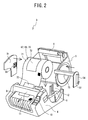
FIG. 2 is an exploded perspective view of the printer; -
FIG. 3 is a perspective view of a roll paper holder (DT roll); -
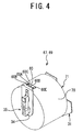
FIG. 4 is a perspective view of a roll paper holder (DK roll) as viewed from underneath; -
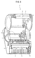
FIG. 5 is a perspective view showing the printer in a condition where its cover is open; -
FIG. 6 is another perspective view showing the printer in a condition where its cover is open; -
FIG. 7 is a block diagram showing an electrical constitution of the printer; -
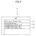
FIG. 8 is a conceptual diagram of storage areas of a RAM; -
FIG. 9 is a block diagram showing an electrical constitution of the personal computer; -
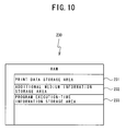
FIG. 10 is a conceptual diagram of storage areas of a RAM of the personal computer; -
FIG. 11 is a schematic table of a setting file storage area; -
FIG. 12 is an illustration of a custom label tool screen, which is a "setting alteration screen" which is displayed on a monitor of the personal computer and on which an operator enters medium information; -
FIG. 13 is an anterior half of a flowchart of setting alteration processing which is performed by the personal computer; -
FIG. 14 is a posterior half of the flowchart of the setting alteration processing which is performed by the personal computer; -
FIG. 15 is a flowchart of advanced setting processing, which is a subroutine of the setting alteration processing flowchart; -
FIG. 16 is an illustration of a screen on which advanced settings are displayed; -
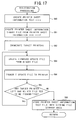
FIG. 17 is a flowchart of registration processing, which is a subroutine of the setting alteration processing flowchart; -
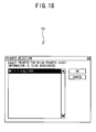
FIG. 18 is an illustration of a printer selection screen; -
FIG. 19 is an illustration of a confirmation screen; -
FIG. 20 is an illustration of an update utility screen; -
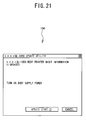
FIG. 21 is an illustration of another update utility screen; -
FIG. 22 is an illustration of a further confirmation screen; and -
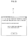
FIG. 23 is an illustration of a further another update utility screen. - The following will describe a
printing system 1 of an embodiment according to the present invention with reference to the drawings. - First, the
printing system 1 will be described with reference toFIGS. 1-3 . Theprinting system 1 consists of aprinter 3 and a knownpersonal computer 2 connected to each other with acable 18. Theprinter 3 contains a roll paper holder 67 and prints on a die-cut label 72 stuck to atape 71 wound around the roll paper holder 67. - Next, the
printer 3 will be described with reference toFIGS. 2-6 . As shown inFIGS. 2 ,5 , and6 , on a lower-part chassis 4 of theprinter 3, acover 5 is axially supported in such a manner that it can swing around. The lower-part chassis 4 under thecover 5 is equipped with a roll paperholder housing section 12 that houses the roll paper holder 67 around which thetape 71 is wound. At the right and left ends of the roll paperholder housing section 12, roll paperholder support sections cover 5, aroller 8 is mounted which guides thetape 71 as it is pulled out of the roll paper holder 67. Further, on the front side of the lower-part chassis 4 of theprinter 3, aprint mechanism section 11 is mounted which including a thermal head type print mechanism (not shown). Additionally, at the lower part of theprint mechanism section 11, a rollpaper discharge outlet 9 is formed that discharges thetape 71 which has printed information on it. Moreover, at the right end of the front face of the lower-part chassis 4, anindication lamp 10 is provided. - Further, as shown in
FIG. 5 , asensor cover 15 is mounted on the right of the roll paperholder housing section 12 with a screw in an attachable-and-detachable manner. A determiningconcave portion 14 is provided under thesensor cover 15 as shown inFIG. 6 where thesensor cover 15 is detached. - Now, the determining
concave portion 14 will be described below. As shown inFIG. 6 , in the determiningconcave portion 14, five sheet determination sensors SS1, SS2, SS3, SS4, and SS5 are arranged in an L-shape. The sheet determination sensors SS1-SS5 are constituted of a micro push button switch or the like each and used to determine the type of various kinds of sheets, the material of a thermo-sensitive sheet, the width of a roll tape, and the like. The sheet determination sensors SS1-SS5 are each a known mechanical switch consisted of a plunger, a micro-switch, etc. The upper end of each of the plungers is equipped so that it protrudes from the bottom of the determiningconcave portion 14. In the determiningconcave portion 14 as described above, the sheet determination sensors SS1-SS5 detect the existence ofsensor holes 60A-60E respectively (seeFIG. 4 ) which are formed in asheet determination section 60 of a DK roll 69. Then, based on ON/OFF signals provided from those sheet determination sensors SS1-SS5 in a control section 40 (seeFIG. 7 ) described below, the type of a tape loaded to the DK roll 69, the width (LW) and the length (LL) of a die-cut label, the material of a thermo-sensitive sheet, etc. are identified respectively. - It should be noted that when the
sensor cover 15 is detached, the plungers of the sheet determination sensors SS1-SS5 protrude from the bottom of the determiningconcave portion 14 at all times, to provide the OFF state of the micro-switches. That is, if any one of the sensor holes 60A-60E in thesheet determination section 60 faces to the corresponding one of the sheet determination sensors SS1-SS5, its plunger is in an un-pressed state. Therefore, its micro-switch is turned OFF and the corresponding one of the sheet determination sensors SS1-SS5 outputs the OFF signal. On the other hand, if any one of the sensor holes 60A-60E in thesheet determination section 60 does not face to the corresponding one of the sheet determination sensors SS1-SS5, its plungers is pressed. Therefore, its micro-switch is turned ON and the corresponding one of the sheet determination sensors SS1-SS5 outputs the ON signal. In such a manner, according to the arrangement of the sensor holes 60A-60E in thesheet determination section 60, the sheet determination sensors SS1-SS5 will output a five-bit signal composed of "0" and "1". If the sheet determination sensors SS1-SS5 are all in the OFF state, that is, if the roll paper holder 67 is not loaded, the five-bit signal of "00000" will be output. - On the other hand, when the
sensor cover 15 is attached, the plungers of the sheet determination sensors SS1-SS5 are all pressed always, to provide the ON state of the micro-switches. In this case, the ON signal is output from all of the sheet determination sensors SS1-SS5. That is, when thesensor cover 15 is attached, the five-bit signal of "11111" will be output. - Further, as shown in
FIG. 7 , theprint mechanism section 11 includes athermal head 13 and a platen roller (not shown). Thetape 71 is transferred in a condition where it is sandwiched between thethermal head 13 and the platen roller. By energizing the heater elements of thethermal head 13 selectively and intermittently during this lapse of time of transferring, a desired image is printed on a predetermined region of the surface of the die-cut label 72 on thetape 71. - Next, the roll paper holder 67 will be described with reference to
FIGS. 2-4 . The roll paper holders 67 are roughly split into two types based on whether they have the later-describedsheet determination section 60. The roll paper holder 67 shown inFIG. 3 is of a type of holding a DT roll 68 which does not have asheet determination section 60. Aroll paper unit 70 is constituted by winding thetape 71 around a hollow core. In the case of the DT roll 68, theroll paper unit 70 is sandwiched between afirst sandwich member 31 and asecond sandwich member 32. Aroll shaft 73 is fixed to thesecond sandwich member 32. On thefirst sandwich member 31, afitting section 33 is formed to which the tip of theroll shaft 73 is fitted in an attachable and detachable manner, to sandwich theroll paper unit 70 between thefirst sandwich member 31 and thesecond sandwich member 32 so that they may be united in constitution. On the outside of thesecond sandwich member 32, a square pole-shapedconvex portion 34 is formed which is held in a condition where it is inserted into a gap between roll paperholder support sections 6. Also on thefirst sandwich member 31, a square pole-shaped convex portion (not shown) is formed which is held in a condition where it is inserted into a gap between roll paperholder support sections 7. Since thefirst sandwich member 31 and thesecond sandwich member 32 are constituted to be attachable and detachable, theroll paper unit 70 can be replaced. Accordingly, when a roll of paper is used up, only theroll paper unit 70 can be replaced. It is also possible to replace theroll paper unit 70 with one on which a different type oftape 71 is wound. It should be noted that to replace the existing one with theroll paper unit 70 having a different width of thetape 71, besides this newroll paper unit 70, it is also necessary to replace such asecond sandwich member 32 as to have aroll shaft 73 having a length that matches the width of anew tape 71. In the case of the DK roll 68, only theroll paper unit 70 can be replaced when its roll of paper is used up, thereby the generation of garbage can be prevented. - The roll paper holder 67 shown in
FIG. 4 is of a type of holding the DK roll 69 having the later-describedsheet determination section 60. As shown inFIG. 4 , in contrast to the above-described DT roll 68, asecond sandwich member 35 has thesheet determination section 60 at its tip (lower end in a condition where it is loaded in the roll paper holder housing section 12). In thesheet determination section 60, the sensor holes 60A-60E are formed which represent the type of the roll paper holder 67. Further, in contrast to the DT roll 68 in which thefirst sandwich member 31 and thesecond sandwich member 32 are configured to be attachable and detachable, the DK roll 69 has such a configuration that thefirst sandwich member 31 is fixed to theroll shaft 73 and so theroll paper unit 70 cannot be replaced. - The DK roll 69 is used as loaded in the roll paper
holder housing section 12 in a condition where thesensor cover 15 is detached from the roll paperholder housing section 12. In contrast, the DK roll 68 is used as loaded in the roll paperholder housing section 12 in a condition where thesensor cover 15 is attached to the roll paperholder housing section 12. - Next, the electrical configuration of the
printer 3 will be described with reference toFIG. 7 . As shown inFIG. 7 , theprinter 3 is equipped with acontrol section 40 that conducts control over it. Thecontrol section 40 includes aCPU 52 that controls the devices of theprinter 3 and an input/output interface 50, aROM 55, and aRAM 56 that are connected to theCPU 52 via adata bus 51. - To the input/
output interface 50 are connecteddrive circuits port 25, theindication lamp 10, and the sheet determination sensors SS1-SS5. The drive circuit 48 drives thethermal head 13. Thedrive circuit 42 drives a tapecutter drive motor 41 that operates atape cutter 17. Thedrive circuit 49 drives atape feed motor 47. TheUSB port 25 connects with thepersonal computer 2. Further, a USB cable is connected to theUSB port 25 and then to thepersonal computer 2. - Further, in the
ROM 55, print drive control program, a parameter table, and the like are stored. The print drive control program executes reading the data from a print data storage area 561 (seeFIG. 8 ) in theRAM 56, to drive thethermal head 13 and thetape feed motor 47. The parameter table is used to determine a duty ratio for determining the amount of print energy with which to drive thethermal head 13. Further, theRAM 56 stores print data and the like transmitted from thepersonal computer 2. Further, apower supply section 57 supplies power in a condition where it is connected to thedrive circuits control section 40. - Next, the storage areas of the
RAM 56 in theprinter 3 will be described below with reference toFIG. 8 . As shown inFIG. 8 , theRAM 56 has the printdata storage area 561, a reception mediuminformation storage area 562, a program execution-timeinformation storage area 563 and the like. The printdata storage area 561 stores print data. The reception mediuminformation storage area 562 stores medium information transmitted from thepersonal computer 2. The program execution-timeinformation storage area 563 stores temporary data which occurs during the execution of a program. TheRAM 56 further has various storage areas besides those illustrated. - Next, the
personal computer 2 of the print data creation apparatus will be described below with reference toFIGS. 1 and9 . As shown inFIG. 9 , thepersonal computer 2 is equipped in itschassis 200 with aCPU 210 that controls thepersonal computer 2. To theCPU 210 are connected aROM 220, aRAM 230, a CD-ROM drive 240, and anHDD 250 via abus 290. In theROM 220, programs such as the BIOS which are are executed by theCPU 210 are stored. TheRAM 230 stores data temporarily. The CD-ROM drive 240 is used to read data from a CD-ROM 241, which is a storage medium of the data inserted into the CD-ROM drive 240. TheHDD 250 is a data storage device. - Furthermore, to the
CPU 210 are connected via the bus 290 a USB (registered trademark)interface 260, adisplay control section 270, and aninput detection section 280 that detects an input from akeyboard 281, amouse 282 which are connected to theinput detection section 280. TheUSB interface 260 is used to establish communication with an external device including theprinter 3. Thedisplay control section 270 performs screen display processing for amonitor 271, on which an operation display screen appears. Thekeyboard 281 and themouse 282 are used by the user for inputting operations. It should be noted that thepersonal computer 2 may be equipped with a floppy (registered trademark) disk drive, a section to input and output voices etc., a variety of interfaces, etc. - It should be noted that the CD-
ROM 241 stores a print data creation program, settings and data to be used when executing this program, etc. When the CD-ROM 241 is introduced, the contents of the CD-ROM 241 will be stored into a program storage area 251 (seeFIG. 9 ) and a program-related information storage area 252 (seeFIG. 9 ) which are arranged in theHDD 250. It should be noted that the method for acquiring the print data creation program for thepersonal computer 2 and data and the like which are used by this program is not limited to the CD-ROM 241 but it may be any other recording medium such as a floppy (registered trademark) disk and an MO (Magneto Optic Disc). Further, those program and data may be acquired from any other terminal on a network by connecting thepersonal computer 2 to the network. - Next, storage areas arranged in the
HDD 250 of thepersonal computer 2 will be described below with reference toFIG. 9 . As shown inFIG. 9 , theHDD 250 has theprogram storage area 251, the program-relatedinformation storage area 252, a settingfile storage area 253, and the like. Theprogram storage area 251 stores the print data creation program and other various programs which are executed by thepersonal computer 2. The program-relatedinformation storage area 252 stores information such as settings, initial values, data, and the like which are necessary in executing the program. The settingfile storage area 253 stores setting information about a medium loaded in the roll paper holder 67. TheHDD 250 further has various storage areas besides those illustrated. - Subsequently, storage areas arranged in the
RAM 230 of thepersonal computer 2 will be described below with reference toFIG. 10 . As shown inFIG. 10 , theRAM 230 has a printdata storage area 231, an additional mediuminformation storage area 232, a program execution-timeinformation storage area 233, and the like. The printdata storage area 231 stores print data. The additional mediuminformation storage area 232 stores medium information to be added to theprinter 3. The program execution-timeinformation storage area 233 stores temporary data which is used during the execution of the program. TheRAM 230 further has various storage areas besides those illustrated. - Now, the setting
file storage area 253 in theHDD 250 of thepersonal computer 2 will be described below. As shown inFIG. 11 , the settingfile storage area 253 of the present embodiment has a name field, a tape type field, a label width field, a label length field, a mount portion width field, an inter-label distance field, a width-directional margin field, a length-directional margin field, and the like. The name field stores the name of the roll paper holder 67. The tape type field stores the type of tapes (which identifies the shape and the material of long tapes, die-cut labels, and the like). The label width field stores the width of the die-cut label 72 loaded in the roll paper holder 67. The label length field stores the length of the die-cut label 72 loaded in the roll paper holder 67. Further, the mount portion width field stores the length of a tape width-directional margin of thetape 71 loaded in theroll paper unit 70 except for the die-cut label 72. The inter-label distance field stores a distance between the die-cutlabels 72 on thetape 71 loaded in the roll paper holder 67. The width-directional margin field stores the length of a width-directional margin on the die-cut label 72. The length-directional margin field stores the length of a length-directional margin on the die-cut label 72. - Next, printer setting alteration processing for the
personal computer 2 will be described below with reference toFIGS. 12-17 . - If "CUSTOM LABEL TOOL" in a "DEVICE SETTING" menu on a property screen of the printer is activated on the screen of the
monitor 271 of thepersonal computer 2, a customlabel tool screen 100 such as shown inFIG. 12 will appear on the screen of themonitor 271 of thepersonal computer 2. The DT roll 68 is capable of loading any tape therein. The custom label tool is used to accommodate a variety of tapes by accomplishing matching between the printer drive of thepersonal computer 2 and the firmware of theprinter 3. The customlabel tool screen 100 has on it a name entry field, a printer sheet type field, a labelwidth entry field 107, a labellength entry field 108, a mount portion width field, an inter-label distance field, a width-directional margin field 109, and a length-directional margin field as well as an import button, an initial value button, a new button, a deletion button, a high-degree setting button, a registration button, an export button, a cancel button, and the like. Further, thecustom label screen 100 will show on it the size of a label that corresponds to a value entered in each of the fields. - It should be noted that the name field is used to enter, as one example, the name of a printer sheet in the roll paper holder 67, which name can be entered in a text composed of one through 31 one-byte characters or one through 15 two-byte characters. Further, the printer sheet type field is capable of selecting a long tape or a die-cut label in it. Corresponding to what is selected in this printer sheet type field, the picture of a printer sheet that appears on the screen will be changed. If the long tape is selected, none of the label
length entry field 108 and the inter-label distance field will be displayed out of the labelwidth entry field 107, the labellength entry field 108, the mount portion width field, the inter-label distance field, the width-directional margin field 109, and the length-directional margin field. Further, one example of a range in which a numeral can be entered in the labelwidth entry field 107 is 12-102mm and one example of a range in which a numeral can be entered in the labellength entry field 108 is 25-255mm. It should be noted that if the product is bound for the USA, one example of the range in which a numeral can be entered in the labelwidth entry field 107 is 0.47-4.02 inches and one example of the range in which a numeral can be entered into the labellength entry field 108 is 0.98-10.04 inches. It should be noted that the value of the width of the mount portion is displayed on the screen but no numeral can be entered as the value of the width. The total label width may come in any one of the seven values of 19, 32, 42, 54, 66, 80.2, and 105. 6; however, the practical effective label width is determined by the equation of "total label width-2x2" (mm). If a label width value is entered into the labelwidth entry field 107, a minimum total label width value out of those seven label width values will be selected which is not smaller than "the entered label width+2x2" (mm). Then, the "(total label width-label width)/2" will be the width of the mount portion. The inter-label distance is displayed on the screen but no numeral can be entered as the value of the distance because its width is fixed to 6mm. It should be noted that if a numeral is entered or changed as the value of the label width or length, the value will also be updated in conjunction with it at the left side on the screen. - Further, a length of the label's width-directional margin is entered into the width-
directional margin field 109. The default value of the length of this margin is a width-directional value of 1.5mm. In the case of millimeter-unit representation, the value will take on the numeral of width-directional (0 through label width/2-0.1) and given in units of 0.1mm. On the other hand, in the case of inch-unit representation, the value will take on the numeral of width-directional (0 through label width/2-0.01) and given in units of 0.01 inch. It should be noted that the value of the length-directional margin is displayed on the screen but no numeral can be entered as the value of the length-directional margin. The length-directional margin will take on a value of 3mm if the label length is equal to or less than 100mm and the value of "label lengthx0.03" (mm) if the label length is greater than 100mm. - Next, a main routine will be described below with reference to
FIGS. 13 and14 . It should be noted thatFIG. 13 shows the anterior half andFIG. 14 shows the posterior half of the flowchart of the main routine. First, a name is entered into the name entry field on the custom label tool screen 100 (YES at S10). If the name exists already in the name entry field, the name is changed to be the entered name -(S11) . Further, if a printer sheet type is selected in the printer sheet type field (YES at S12), the printer sheet type is changed to the selected printer sheet type (S13). Further, if the "IMPORT BUTTON" is clicked (YES at S14), an external file to be read can be entered (S15), so that when this external file (text file) is read, the information is updated (S16). If the "NEW BUTTON" is clicked (YES at S17), a new printer sheet is created (S18). Specifically, the name field, the label width field, and the label length field are left blank and the width-directional margin field, the length-directional margin field, and the printer sheet's mount portion width field take on their respective default values. The defaults values are 1.5mm, 3.0mm, and 1.5mm respectively. And the high-degree setting which will be described later also takes defaults value. Further, if the "INITIAL VALUE BUTTON" is clicked (YES at S19), all changes made by the user are canceled and returns the setting contents to those upon installation of the printer driver (S20). Specifically, the screen displays on it a message which says "ALL DATA CREATED SO FAR WILL BE ABANDONED AND THE STATE UPON INSTALLATION IS RECOVERED. OK?" and an OK button and a cancel button. If the OK button is then clicked, the contents of settings are returned to those upon installation of the printer driver. - Further, if the "DELETE" button is clicked (YES at S21), the displayed printer sheet is deleted (S22). Specifically, if a printer sheet is already registered, the screen displays on it a message which says "SO-AND-SO WILL BE DELETED. OK?" as well as the OK button and the CANCEL button. If the OK button is then clicked, the registered printer sheet is deleted. If no printer sheet is registered, the screen displays on it a message which says "So-and-so is not registered. ("DELETE" button is operative to delete a displayed printer sheet already registered)" and the OK button. If the OK button is then clicked, dialog is closed. It should be noted that if there is the information about a printer sheet other than the deleted printer sheet (YES at S23), after deleting the registered printer sheet, the information about this different printer sheet is displayed (S24). If there is no other printer sheet information (NO at S23), the name field, the label width field, and the label length field of the printer sheet go blank and the other information is set an initial value (S25). Subsequently, the remaining part of the main routine will be described with reference to
FIG. 14 . If values are entered into the label width field, the label length field, and the width-directional margin field (YES at S26), the value of the label width, the label length, and the width-directional margin are changed in accordance with those entered values (S27). - Further, if the "HIGH-DEGREE SETTING BUTTON" is clicked (YES at S28), the process performs high-degree setting (S29). The high-degree setting is performed by a subroutine shown in
FIG. 15 . Specifically, a high-degree setting screen 120 shown inFIG. 16 appears on the screen of themonitor 271 of the personal computer 2 (S50). The high-degree setting screen 120 displays a screen on which any one of three levels of low, medium, and high levels is selected as the energy rank of thethermal head 13 in printing. On the high-degree setting screen 120, any one of "LOW", "MEDIUM", and "HIGH" is displayed in a list box. The default setting is "MEDIUM". The "MEDIUM" means ±0% of energy which is used in printing of ordinary thermo-sensitive paper. The "LOW" means -10% of the medium energy and the "HIGH" means +10% of the medium energy. It should be noted that the high-degree setting screen 120 displays on it "IF TOO MUCH OF DATA IS TO BE PRINTED, EVEN "HIGH" ENERGY RANK MAY NOT BE EFFECTIVE". If any one of the energy ranks is selected (YES at S51), the existing rank is updated with this energy rank (S52). If the OK button is then clicked (YES at S53), the process ends the high-degree setting processing and returns to the main routine shown inFIG. 14 . On the other hand, if the CANCEL button is clicked (YES at S54), the process brings the energy rank back to that upon appearance of the high-degree setting screen (S55) and returns to the main routine shown inFIG. 14 . It should be noted that if the CANCEL button is not clicked (NO at S54), the process returns to S50. - Next, if the registration button is clicked in the main routine shown in
FIG. 14 (S30), the process performs registration processing (S31). Specifically, the registration processing is performed by a subroutine for the registration processing shown inFIG. 17 . In the registration processing, first, a printer sheet information text file of a printer sheet displayed on the customlabel tool screen 100 is created (S60). The printer sheet information text file includes the information about all of printer sheets including the displayed one and is read by the custom label tool to be used. - Subsequently, a printer sheet information binary file is created from the printer sheet information text file (S61). In processing at this step of S61, the text file is converted by a printer sheet compile tool into a binary file (ptd) which is used by the printer driver. Now, one example of the details of creating a binary file (ptd) will be described below. First, the printer sheet compile tool is activated by entering "ptq110pc.exe/S/L = <log file> <input file> <output file>" with an input/output file as an argument. In this case, the input file is "ptql10ed.txt", option "/S" means "no screen output (UI) is provided", and option "/L" means "logging is performed". If the aforementioned argument is given, the printer sheet compile tool creates a ptd file without outputting it onto the screen. If an error occurs, this error is written into a log file. If the log has an error written in it, the custom label tool displays this error.
- Next, as shown in
FIG. 18 , aprinter selection screen 101 appears on themonitor 271 of the personal computer 2 (S62). A name of theprinter 3, which is connected to thepersonal computer 2 and whose firmware is to be updated, is displayed on theprinter selection screen 101. In this case, if a plurality of printers is targeted, their names will be all enumerated. If the CANCEL button is then clicked, atermination confirmation screen 102 shown inFIG. 19 will be displayed. If "YES" is then clicked, the process ends the processing. On the other hand, if "NO" is clicked, the process returns to theprinter selection screen 101 shown inFIG. 18 . On theprinter selection screen 101, a printer that corresponds to the marked printer name field displayed will be subjected to the updating of the firmware. - If the OK button is then clicked on the
printer selection screen 101, a file (bin) for updating the firmware for thetarget printer 3 is created from the printer sheet information binary file which is created in the processing of S61 (S63). This processing is performed by a printer sheet addition tool when it reads the printer sheet information binary file (ptd). If the power supply of thetarget printer 3 is in the ON state, the process displays anupdate utility screen 103 shown inFIG. 20 and transmits an update file to the target printer 3 (S64). - On the other hand, if the power supply of the
target printer 3 is not in the ON state, "PRINTER SHEET INFORMATION IN THE BODY IS UPDATED. TURN ON THE POWER SUPPLY OF THE BODY" is displayed on anupdate utility screen 104 shown inFIG. 21 , to prompt the user to turn ON the power supply of thetarget printer 3. If the CANCEL button is clicked on theupdate utility screen 104, aconfirmation screen 105 shown inFIG. 22 is displayed and the user is prompted to confirm that the processing may be terminated. - If a plurality of printers is selected on the
printer selection screen 101 shown inFIG. 18 , the processing of S63 through S65 is repeated (YES at S65 → S63 → S64) . If there is no more update file that is not transmitted (NO at S65), the printer sheet information text file is stored into the setting file storage area (driver folder) on theHDD 250 in the personal computer 2 (S66). Then, anupdate utility screen 106 shown inFIG. 23 is displayed, and the user is prompted to restart thepersonal computer 2 to enable a new driver. Then, the process returns to the main routine shown inFIG. 14 . In such a manner, in a print data creation apparatus of the present embodiment and a print system including the print data creation apparatus, only by changing the settings of the printer on the setting alteration screen of the print data creation apparatus, it is possible to update setting information to be referred to by the printer driver and the firmware for the printer. - It should be noted that if the CANCEL button is clicked on the custom
label tool screen 100 shown inFIG. 12 (YES at S32), the process abandons the input information (S33) and ends the processing. - Also, if the EXPORT button (E) is clicked on the custom
label tool screen 100 shown inFIG. 12 as described in the main routine ofFIG. 14 (S34), a folder to which a file is to be output is input (S35) and a printer sheet information text file is created in this folder (S36). Subsequently, a printer sheet information binary file (ptd) is created from this printer sheet information text file (S37).
Subsequently, an update file (bin) of the firmware for thetarget printer 3 is created from the binary file (ptd) (S38). It should be noted that in this series of export processing pieces, a text file is created which includes the printer sheet information text file only of printer sheet information being displayed, the printer sheet information binary file (ptd), and all the printer sheet information managed by the update file (bin) of the firmware and the tool. Therefore, those four files can be incorporated into an installer to be distributed. It is thus possible to activate the printer sheet addition tool upon installation of the driver, to also update the firmware of theprinter 3. - It should be noted that the present disclosure is not limited to the embodiment detailed above but can be modified variously. In the above-described embodiment, the
printer 3 is not limited to such a type as to print information on a tape loaded in a roll paper holder but may be a printing apparatus that prints information on tapes, cut sheets, continuous forms, etc. loaded in a cassette. Further, those printing apparatuses may employ such a printing method as an ink jet method or a laser printing method. The items of medium information may as well be caused to correspond to the print medium or the printing apparatus. Further, although the above embodiment has used thepersonal computer 2 to create print data, any other type of computer may be employed. - In the present embodiment, it is assumed that if the five-bit signal of "11111" is detected by the sheet determination sensors SS1-SS5, the DT roll 68 is identified, and any other value except "00000" is detected, the DK roll 69 is identified. However, the DT roll 68 need not always be identified if "11111" is detected but may be identified if a predetermined value other than "00000" is detected. The number of the predetermined values need not be one only.
- The present embodiment has employed such a configuration as to attach the
sensor cover 15 to theprinter 3 when using the DT roll 68. However, to use the DT roll 68, thesheet determination section 60 may be equipped instead of attaching thesensor cover 15. However, if thesensor cover 15 is attached, thesheet determination section 60 can be eliminated from the DT roll, thereby the amount of materials to be used can be reduced.
Claims (14)
- A print data creation apparatus (2) connectable to a printer (3) for printing on a print medium (71)to create print data to be printed by the printer (3), the print data creation apparatus (2) comprising:a display device (271) for displaying a variety of information;a setting alteration screen display control device (270) for displaying a setting alteration screen (100) for using to change settings of the printer (3) on the display device (271);a setting file storage device (253) for storing a setting file including setting information to be referred to by a printer driver of the printer (3);a setting file alteration device (210, S66) for changing contents of the setting file stored in the setting file storage device (253) based on the settings of the printer (3) changed on the setting alteration screen (100);an update information creation device (210, S63) for creating update information for updating firmware of the printer (3) in response to a change in the setting file brought about by the setting file alteration device (210) ; andan update information transmission device (210, S64) for transmitting the update information created by the update information creation device (210) to the printer (3) .
- The print data creation apparatus (2) according to claim 1, further comprising:a numeral display section (107, 108, 109) that is arranged on the setting alteration screen (100) for displaying each numeral which is set to each of items to be set, wherein:the numerical in the numerical display section (107, 108, 109) is configurable arbitrarily within a predetermined range.
- The print data creation apparatus (2) according to claim 1 or 2, wherein
the print data creation apparatus (2) is capable of connecting to a plurality of printers (3), and
the update information transmission device (210) is configured to transmit the same update information to the plurality of printers (3) which uses the same printer driver. - The print data creation apparatus (2) according to any one of claims 1 to 3, wherein
the printer setting items displayed on the setting alteration screen (100) are information relating to a tape (71) as a print medium attachable to the printer (3). - The print data creation apparatus (2) according to claim 4, wherein
if the tape (71) is a die-cut tape in which a plurality of labels (72) each of which is formed into a predetermined shape are arranged continually on a sheet of release paper (71), a size of the label (72) can be set on the setting alteration screen (100). - The print data creation apparatus (2) according to any one of claims 1 to 5, wherein
the setting file whose contents are changed by the setting file alteration device (210) and the update information created by the update information creation device (210) can be output as a file for incorporating into a driver installer which installs the printer driver into the print data creation apparatus (2). - A computer-readable control program for a print data creation apparatus (2) connectable to a printer (3) for printing on a print medium (71) to create print data to be printed by the printer (3), the control program comprising:setting alteration screen display control instructions for displaying a setting alteration screen (100) which is used to change settings of the printer (3);setting file alteration instructions for changing contents of a setting file including setting information which is referred to by a printer driver of the printer (3) based on the settings of the printer (3) changed on the setting alteration screen (100);update information creation instructions for creating update information which updates firmware of the printer (3) in response to a change in the setting file brought about by the setting file alteration instructions; andupdate information transmission instructions for transmitting the update information created by the update information creation instructions to the printer (3).
- The control program for the print data creation apparatus (2) according to claim 7, further comprising
numeral display instructions for displaying each numeral which is arbitrarily set in a predetermined range arranged on the setting alteration screen (100) for each of items to be set. - The control program for the print data creation apparatus (2) according to claim 7 or 8, wherein
the update information transmission instructions transmit the same update information to a plurality of printers (3) which uses the same printer driver. - The control program for the print data creation apparatus (2) according to any one of claims 7 to 9, wherein
the printer setting items displayed on the setting alteration screen (100) are information relating to a tape (71) as a print medium attachable to the printer (3). - The control program for the print data creation apparatus (2) according to claim 10, wherein
if the tape (71) is a die-cut tape in which a plurality of labels (72) each of which is formed into a predetermined shape are arranged continually on a sheet of release paper (71), a size of the label (72) can be set on the setting alteration screen (100). - The control program for the printing data creation apparatus according to any one of claims 7 to 11, wherein
the setting file whose contents are changed by the setting file alteration instructions and the update information which is created by the update information creation instructions can be output as a file which is incorporated into a driver installer which installs the printer driver into the print data creation apparatus (2) . - A printing system comprising:the printing data creation apparatus (2) according to claim 1; anda printer (3) that prints the print data on a print medium, the printer (3) including:an update information reception device (25) for receiving the update information transmitted by the update information transmission device; anda firmware update device (52) for updating the firmware of the printer (3) based on the update information received by the update information reception device (25).
- A method to control a print data creation apparatus (2) connectable to a printer (3) for printing on a print medium (71) to create print data to be printed by the printer (3), comprising:displaying a setting alteration screen (100) which is used to change settings of the printer (3);changing contents of a setting file including setting information which is referred to by a printer driver of the printer (3) based on the settings of the printer (3) changed on the setting alteration screen (100);creating update information which updates firmware of the printer (3) in response to a change in the setting file brought about by the setting file alteration instructions; andtransmitting the update information created by the update information creation instructions to the printer (3).
Applications Claiming Priority (1)
| Application Number | Priority Date | Filing Date | Title |
|---|---|---|---|
| JP2007111022A JP4910857B2 (en) | 2007-04-19 | 2007-04-19 | Printing system, printing data creation device and computer program |
Publications (2)
| Publication Number | Publication Date |
|---|---|
| EP1983423A2 true EP1983423A2 (en) | 2008-10-22 |
| EP1983423A3 EP1983423A3 (en) | 2010-07-14 |
Family
ID=39535688
Family Applications (1)
| Application Number | Title | Priority Date | Filing Date |
|---|---|---|---|
| EP08007469A Withdrawn EP1983423A3 (en) | 2007-04-19 | 2008-04-16 | Printing system, print data creation apparatus and computer-readable control program for the print data creation apparatus |
Country Status (4)
| Country | Link |
|---|---|
| US (1) | US20080259398A1 (en) |
| EP (1) | EP1983423A3 (en) |
| JP (1) | JP4910857B2 (en) |
| CN (1) | CN101290561B (en) |
Cited By (2)
| Publication number | Priority date | Publication date | Assignee | Title |
|---|---|---|---|---|
| EP2189291A3 (en) * | 2008-11-20 | 2010-09-22 | Bizerba GmbH & Co. KG | Device for processing labels and/or paper rolls |
| EP2317435A1 (en) * | 2009-10-30 | 2011-05-04 | Samsung Electronics Co., Ltd. | Electronic device and method for making upgraded firmware |
Families Citing this family (19)
| Publication number | Priority date | Publication date | Assignee | Title |
|---|---|---|---|---|
| JP5532848B2 (en) | 2009-11-20 | 2014-06-25 | セイコーエプソン株式会社 | Recording control apparatus, control method, and program |
| JP5783679B2 (en) * | 2010-01-15 | 2015-09-24 | キヤノン株式会社 | Printing apparatus, printing system, control method, and program |
| JP5359912B2 (en) * | 2010-02-09 | 2013-12-04 | セイコーエプソン株式会社 | Setting information management system, printer and electronic device control method |
| JP5533549B2 (en) * | 2010-10-20 | 2014-06-25 | ブラザー工業株式会社 | Application software, printing system, and recording medium |
| JPWO2014091707A1 (en) | 2012-12-13 | 2017-01-05 | セイコーエプソン株式会社 | Receipt printing system, receipt printing system control method, and control apparatus |
| JP5875566B2 (en) * | 2012-12-27 | 2016-03-02 | キヤノンファインテック株式会社 | Image forming system and image forming apparatus |
| JP6398174B2 (en) * | 2013-10-22 | 2018-10-03 | セイコーエプソン株式会社 | Recording device |
| JP2015219587A (en) * | 2014-05-14 | 2015-12-07 | 株式会社リコー | Image forming apparatus, image forming method, and image forming program |
| PL410736A1 (en) * | 2014-12-22 | 2016-07-04 | Zortrax Spółka Z Ograniczoną Odpowiedzialnością | Method for processing and recording of the 3D printer control process parameters |
| JP6507903B2 (en) * | 2015-07-21 | 2019-05-08 | 富士通株式会社 | Interval adjustment program, interval adjustment method and interval adjustment device |
| JP2018055465A (en) * | 2016-09-29 | 2018-04-05 | セイコーエプソン株式会社 | Printer and control method of printer |
| JP6857331B2 (en) | 2017-11-30 | 2021-04-14 | ブラザー工業株式会社 | Printed matter creation program and printed matter creation device |
| JP7119429B2 (en) * | 2018-03-02 | 2022-08-17 | ブラザー工業株式会社 | Computer program, data transmission method and terminal device |
| JP7099029B2 (en) * | 2018-04-27 | 2022-07-12 | ブラザー工業株式会社 | program |
| JP7132865B2 (en) * | 2019-02-14 | 2022-09-07 | サトーホールディングス株式会社 | Printer, printer control method and program |
| JP7234688B2 (en) | 2019-02-27 | 2023-03-08 | ブラザー工業株式会社 | Program, application, information processing device |
| JP7263837B2 (en) | 2019-02-27 | 2023-04-25 | ブラザー工業株式会社 | Program, application, information processing device |
| JP7234687B2 (en) * | 2019-02-27 | 2023-03-08 | ブラザー工業株式会社 | modules and programs |
| US11435965B2 (en) | 2019-06-14 | 2022-09-06 | Brother Kogyo Kabushiki Kaisha | Storage medium storing program for converting first data into second data to be inputted to printer |
Citations (1)
| Publication number | Priority date | Publication date | Assignee | Title |
|---|---|---|---|---|
| JP2005258858A (en) | 2004-03-12 | 2005-09-22 | Brother Ind Ltd | Printing system, printing data editing apparatus and printing apparatus |
Family Cites Families (13)
| Publication number | Priority date | Publication date | Assignee | Title |
|---|---|---|---|---|
| JP3285110B2 (en) * | 1994-10-21 | 2002-05-27 | セイコーエプソン株式会社 | Firmware incorporating method and system comprising host device and printer |
| US6147767A (en) * | 1997-09-05 | 2000-11-14 | Comtec Informations Systems, Inc. | Computer system for a printer which stores and operates multiple application programs |
| JP2002215361A (en) * | 2001-01-16 | 2002-08-02 | Canon Inc | Information processor, printing management, device, system and method, storage medium storing computer- readable program, and printing control program |
| JP2003063109A (en) * | 2001-08-28 | 2003-03-05 | Brother Ind Ltd | Print system, printer and computer program |
| JP3863118B2 (en) * | 2002-04-01 | 2006-12-27 | 松下電器産業株式会社 | Receiving device, printing device, and firmware update system |
| JP4036025B2 (en) * | 2002-04-30 | 2008-01-23 | ブラザー工業株式会社 | Printing system |
| US20030231328A1 (en) * | 2002-06-07 | 2003-12-18 | Xerox Corporation | Multiple printer driver |
| CN100409166C (en) * | 2003-02-28 | 2008-08-06 | 松下电器产业株式会社 | Receiving device, printing device and firmware update system |
| US7375837B2 (en) * | 2003-03-25 | 2008-05-20 | Sharp Laboratories Of America, Inc. | User-definable print-option conversion for heterogeneous cluster printing |
| US20070159650A1 (en) * | 2004-06-24 | 2007-07-12 | Ryuichiro Takamatsu | Printing apparatus, and firmware updating method therefor |
| US20060070055A1 (en) * | 2004-09-24 | 2006-03-30 | Hodder Leonard B | Method of updating printer firmware and printing device employing the method |
| JP3856045B2 (en) * | 2005-12-20 | 2006-12-13 | ブラザー工業株式会社 | Communication system and storage medium |
| JP2007257256A (en) * | 2006-03-23 | 2007-10-04 | Konica Minolta Business Technologies Inc | Setting program for printer driver, setting method for printer driver, and print request device |
-
2007
- 2007-04-19 JP JP2007111022A patent/JP4910857B2/en active Active
-
2008
- 2008-04-16 CN CN2008100927943A patent/CN101290561B/en active Active
- 2008-04-16 EP EP08007469A patent/EP1983423A3/en not_active Withdrawn
- 2008-04-17 US US12/148,212 patent/US20080259398A1/en not_active Abandoned
Patent Citations (1)
| Publication number | Priority date | Publication date | Assignee | Title |
|---|---|---|---|---|
| JP2005258858A (en) | 2004-03-12 | 2005-09-22 | Brother Ind Ltd | Printing system, printing data editing apparatus and printing apparatus |
Cited By (2)
| Publication number | Priority date | Publication date | Assignee | Title |
|---|---|---|---|---|
| EP2189291A3 (en) * | 2008-11-20 | 2010-09-22 | Bizerba GmbH & Co. KG | Device for processing labels and/or paper rolls |
| EP2317435A1 (en) * | 2009-10-30 | 2011-05-04 | Samsung Electronics Co., Ltd. | Electronic device and method for making upgraded firmware |
Also Published As
| Publication number | Publication date |
|---|---|
| CN101290561A (en) | 2008-10-22 |
| JP2008269265A (en) | 2008-11-06 |
| CN101290561B (en) | 2013-09-11 |
| EP1983423A3 (en) | 2010-07-14 |
| US20080259398A1 (en) | 2008-10-23 |
| JP4910857B2 (en) | 2012-04-04 |
Similar Documents
| Publication | Publication Date | Title |
|---|---|---|
| US20080259398A1 (en) | Printing system, print data creation apparatus and computer-readable control program for the print data creation apparatus | |
| EP1849614B1 (en) | Label creating system, terminal device and computer program product | |
| AU769561B2 (en) | Administrative print server link for output peripheral device | |
| AU771903B2 (en) | Client print server link for output peripheral device | |
| JP2010117843A (en) | Method and program for setting of setting value of printer | |
| US11780240B2 (en) | Information processing device having acquiring section acquiring remaining tape length, tape printing device, tape printing system, method for controlling information processing device, and storage medium storing program for controlling information processing device | |
| CN101295232A (en) | Means for controlling an image-processing device and computer implemented method for updating an item of configuration information | |
| JP5545542B2 (en) | Software management apparatus and software management system | |
| US8339651B2 (en) | Printer and computer-readable recording medium storing printing program | |
| JP2017165047A (en) | Image formation apparatus, image formation system, setting method, and program | |
| US20050200875A1 (en) | Print system, print data editing unit and print apparatus | |
| JP5791928B2 (en) | Printing system, program, and control method of printing system | |
| CN100379567C (en) | tape printer | |
| KR20050027916A (en) | Printing system and control method therefor | |
| JP2010005961A (en) | Label printer | |
| JP2020149380A (en) | Programs, storage programs and information processing equipment | |
| US11847514B2 (en) | Information processing device, printing apparatus, and method of controlling information processing device | |
| US20220374177A1 (en) | Information processing apparatus, tape printing apparatus, printing system, method of controlling information processing apparatus, and storage medium storing program for controlling information processing apparatus | |
| KR100233128B1 (en) | How to Automatically Set Paper Sources in the Printer Driver | |
| KR100654397B1 (en) | Computer-readable recording medium storing print setting program | |
| JP2005173913A (en) | Printing system, printer driver and printer | |
| JP5621627B2 (en) | Printing device | |
| WO2012073720A1 (en) | Print device | |
| HK1105827A (en) | Image creating apparatus and printing apparatus provided therewith | |
| JP2004249479A (en) | Printer |
Legal Events
| Date | Code | Title | Description |
|---|---|---|---|
| PUAI | Public reference made under article 153(3) epc to a published international application that has entered the european phase |
Free format text: ORIGINAL CODE: 0009012 |
|
| AK | Designated contracting states |
Kind code of ref document: A2 Designated state(s): AT BE BG CH CY CZ DE DK EE ES FI FR GB GR HR HU IE IS IT LI LT LU LV MC MT NL NO PL PT RO SE SI SK TR |
|
| AX | Request for extension of the european patent |
Extension state: AL BA MK RS |
|
| PUAL | Search report despatched |
Free format text: ORIGINAL CODE: 0009013 |
|
| AK | Designated contracting states |
Kind code of ref document: A3 Designated state(s): AT BE BG CH CY CZ DE DK EE ES FI FR GB GR HR HU IE IS IT LI LT LU LV MC MT NL NO PL PT RO SE SI SK TR |
|
| AX | Request for extension of the european patent |
Extension state: AL BA MK RS |
|
| 17P | Request for examination filed |
Effective date: 20101207 |
|
| AKX | Designation fees paid |
Designated state(s): AT BE BG CH CY CZ DE DK EE ES FI FR GB GR HR HU IE IS IT LI LT LU LV MC MT NL NO PL PT RO SE SI SK TR |
|
| STAA | Information on the status of an ep patent application or granted ep patent |
Free format text: STATUS: THE APPLICATION HAS BEEN WITHDRAWN |
|
| 18W | Application withdrawn |
Effective date: 20160315 |