EP1983306A1 - Rotor for rotary encoder and rolling bearing for wheel having same - Google Patents
Rotor for rotary encoder and rolling bearing for wheel having same Download PDFInfo
- Publication number
- EP1983306A1 EP1983306A1 EP07707093A EP07707093A EP1983306A1 EP 1983306 A1 EP1983306 A1 EP 1983306A1 EP 07707093 A EP07707093 A EP 07707093A EP 07707093 A EP07707093 A EP 07707093A EP 1983306 A1 EP1983306 A1 EP 1983306A1
- Authority
- EP
- European Patent Office
- Prior art keywords
- ring
- rotor
- cylindrical portion
- mounting flange
- pulser
- Prior art date
- Legal status (The legal status is an assumption and is not a legal conclusion. Google has not performed a legal analysis and makes no representation as to the accuracy of the status listed.)
- Granted
Links
Images


Classifications
-
- F—MECHANICAL ENGINEERING; LIGHTING; HEATING; WEAPONS; BLASTING
- F16—ENGINEERING ELEMENTS AND UNITS; GENERAL MEASURES FOR PRODUCING AND MAINTAINING EFFECTIVE FUNCTIONING OF MACHINES OR INSTALLATIONS; THERMAL INSULATION IN GENERAL
- F16C—SHAFTS; FLEXIBLE SHAFTS; ELEMENTS OR CRANKSHAFT MECHANISMS; ROTARY BODIES OTHER THAN GEARING ELEMENTS; BEARINGS
- F16C41/00—Other accessories, e.g. devices integrated in the bearing not relating to the bearing function as such
- F16C41/007—Encoders, e.g. parts with a plurality of alternating magnetic poles
-
- B—PERFORMING OPERATIONS; TRANSPORTING
- B60—VEHICLES IN GENERAL
- B60B—VEHICLE WHEELS; CASTORS; AXLES FOR WHEELS OR CASTORS; INCREASING WHEEL ADHESION
- B60B27/00—Hubs
- B60B27/0005—Hubs with ball bearings
-
- B—PERFORMING OPERATIONS; TRANSPORTING
- B60—VEHICLES IN GENERAL
- B60B—VEHICLE WHEELS; CASTORS; AXLES FOR WHEELS OR CASTORS; INCREASING WHEEL ADHESION
- B60B27/00—Hubs
- B60B27/0047—Hubs characterised by functional integration of other elements
- B60B27/0068—Hubs characterised by functional integration of other elements the element being a sensor
-
- B—PERFORMING OPERATIONS; TRANSPORTING
- B60—VEHICLES IN GENERAL
- B60B—VEHICLE WHEELS; CASTORS; AXLES FOR WHEELS OR CASTORS; INCREASING WHEEL ADHESION
- B60B27/00—Hubs
- B60B27/0078—Hubs characterised by the fixation of bearings
- B60B27/0084—Hubs characterised by the fixation of bearings caulking to fix inner race
-
- G—PHYSICS
- G01—MEASURING; TESTING
- G01D—MEASURING NOT SPECIALLY ADAPTED FOR A SPECIFIC VARIABLE; ARRANGEMENTS FOR MEASURING TWO OR MORE VARIABLES NOT COVERED IN A SINGLE OTHER SUBCLASS; TARIFF METERING APPARATUS; MEASURING OR TESTING NOT OTHERWISE PROVIDED FOR
- G01D5/00—Mechanical means for transferring the output of a sensing member; Means for converting the output of a sensing member to another variable where the form or nature of the sensing member does not constrain the means for converting; Transducers not specially adapted for a specific variable
- G01D5/12—Mechanical means for transferring the output of a sensing member; Means for converting the output of a sensing member to another variable where the form or nature of the sensing member does not constrain the means for converting; Transducers not specially adapted for a specific variable using electric or magnetic means
- G01D5/14—Mechanical means for transferring the output of a sensing member; Means for converting the output of a sensing member to another variable where the form or nature of the sensing member does not constrain the means for converting; Transducers not specially adapted for a specific variable using electric or magnetic means influencing the magnitude of a current or voltage
- G01D5/142—Mechanical means for transferring the output of a sensing member; Means for converting the output of a sensing member to another variable where the form or nature of the sensing member does not constrain the means for converting; Transducers not specially adapted for a specific variable using electric or magnetic means influencing the magnitude of a current or voltage using Hall-effect devices
- G01D5/145—Mechanical means for transferring the output of a sensing member; Means for converting the output of a sensing member to another variable where the form or nature of the sensing member does not constrain the means for converting; Transducers not specially adapted for a specific variable using electric or magnetic means influencing the magnitude of a current or voltage using Hall-effect devices influenced by the relative movement between the Hall device and magnetic fields
-
- G—PHYSICS
- G01—MEASURING; TESTING
- G01P—MEASURING LINEAR OR ANGULAR SPEED, ACCELERATION, DECELERATION, OR SHOCK; INDICATING PRESENCE, ABSENCE, OR DIRECTION, OF MOVEMENT
- G01P3/00—Measuring linear or angular speed; Measuring differences of linear or angular speeds
- G01P3/42—Devices characterised by the use of electric or magnetic means
- G01P3/44—Devices characterised by the use of electric or magnetic means for measuring angular speed
- G01P3/443—Devices characterised by the use of electric or magnetic means for measuring angular speed mounted in bearings
-
- G—PHYSICS
- G01—MEASURING; TESTING
- G01P—MEASURING LINEAR OR ANGULAR SPEED, ACCELERATION, DECELERATION, OR SHOCK; INDICATING PRESENCE, ABSENCE, OR DIRECTION, OF MOVEMENT
- G01P3/00—Measuring linear or angular speed; Measuring differences of linear or angular speeds
- G01P3/42—Devices characterised by the use of electric or magnetic means
- G01P3/44—Devices characterised by the use of electric or magnetic means for measuring angular speed
- G01P3/48—Devices characterised by the use of electric or magnetic means for measuring angular speed by measuring frequency of generated current or voltage
- G01P3/481—Devices characterised by the use of electric or magnetic means for measuring angular speed by measuring frequency of generated current or voltage of pulse signals
- G01P3/487—Devices characterised by the use of electric or magnetic means for measuring angular speed by measuring frequency of generated current or voltage of pulse signals delivered by rotating magnets
-
- F—MECHANICAL ENGINEERING; LIGHTING; HEATING; WEAPONS; BLASTING
- F16—ENGINEERING ELEMENTS AND UNITS; GENERAL MEASURES FOR PRODUCING AND MAINTAINING EFFECTIVE FUNCTIONING OF MACHINES OR INSTALLATIONS; THERMAL INSULATION IN GENERAL
- F16C—SHAFTS; FLEXIBLE SHAFTS; ELEMENTS OR CRANKSHAFT MECHANISMS; ROTARY BODIES OTHER THAN GEARING ELEMENTS; BEARINGS
- F16C19/00—Bearings with rolling contact, for exclusively rotary movement
- F16C19/02—Bearings with rolling contact, for exclusively rotary movement with bearing balls essentially of the same size in one or more circular rows
- F16C19/14—Bearings with rolling contact, for exclusively rotary movement with bearing balls essentially of the same size in one or more circular rows for both radial and axial load
- F16C19/18—Bearings with rolling contact, for exclusively rotary movement with bearing balls essentially of the same size in one or more circular rows for both radial and axial load with two or more rows of balls
- F16C19/181—Bearings with rolling contact, for exclusively rotary movement with bearing balls essentially of the same size in one or more circular rows for both radial and axial load with two or more rows of balls with angular contact
- F16C19/183—Bearings with rolling contact, for exclusively rotary movement with bearing balls essentially of the same size in one or more circular rows for both radial and axial load with two or more rows of balls with angular contact with two rows at opposite angles
- F16C19/184—Bearings with rolling contact, for exclusively rotary movement with bearing balls essentially of the same size in one or more circular rows for both radial and axial load with two or more rows of balls with angular contact with two rows at opposite angles in O-arrangement
- F16C19/186—Bearings with rolling contact, for exclusively rotary movement with bearing balls essentially of the same size in one or more circular rows for both radial and axial load with two or more rows of balls with angular contact with two rows at opposite angles in O-arrangement with three raceways provided integrally on parts other than race rings, e.g. third generation hubs
-
- F—MECHANICAL ENGINEERING; LIGHTING; HEATING; WEAPONS; BLASTING
- F16—ENGINEERING ELEMENTS AND UNITS; GENERAL MEASURES FOR PRODUCING AND MAINTAINING EFFECTIVE FUNCTIONING OF MACHINES OR INSTALLATIONS; THERMAL INSULATION IN GENERAL
- F16C—SHAFTS; FLEXIBLE SHAFTS; ELEMENTS OR CRANKSHAFT MECHANISMS; ROTARY BODIES OTHER THAN GEARING ELEMENTS; BEARINGS
- F16C2326/00—Articles relating to transporting
- F16C2326/01—Parts of vehicles in general
- F16C2326/02—Wheel hubs or castors
-
- G—PHYSICS
- G01—MEASURING; TESTING
- G01D—MEASURING NOT SPECIALLY ADAPTED FOR A SPECIFIC VARIABLE; ARRANGEMENTS FOR MEASURING TWO OR MORE VARIABLES NOT COVERED IN A SINGLE OTHER SUBCLASS; TARIFF METERING APPARATUS; MEASURING OR TESTING NOT OTHERWISE PROVIDED FOR
- G01D2205/00—Indexing scheme relating to details of means for transferring or converting the output of a sensing member
- G01D2205/80—Manufacturing details of magnetic targets for magnetic encoders
Definitions
- the present invention relates to a rotor for use in rotary encoder and a wheel rolling bearing assembly including the same.
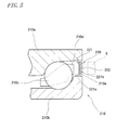
- FIG. 5 is a sectional view showing a rotary encoder in a conventional wheel rolling bearing assembly.
- a wheel rolling bearing assembly 210 includes: an outer ring 210a fixed to a vehicle body via a knuckle (not shown); an inner ring 210b fixed to an axle shaft (not shown) mounted with a wheel (not shown); a plurality of balls 210c as rolling elements interposed between the outer ring 210a and the inner ring 210b; and a cage 210d formed with pocket portions at regular space intervals, the pocket portions receiving the balls 210c.
- the rotary encoder for detecting the number of revolutions of the wheel rolling bearing assembly 210 includes: a rotor 220 fixed to the wheel rolling bearing assembly 210; and a rotation detection sensor S for magnetically detecting the rotation of the rotor 220.
- the rotor 220 is formed from rubber admixed with magnetic powder, such as ferrite powder, and in an annular shape.
- the rotor includes: a magnetized portion 222 circumferentially magnetized in alternating S-polarity and N-polarity; and an annular core portion 221 supporting the magnetized portion 222.
- the core portion 221 further includes: a cylindrical portion 221a press-fitted on an outer periphery of a shoulder 210e of the inner ring 21 0b; and a flange portion 221 b extended radially outwardly from one axial end of the cylindrical portion 221a.
- the core portion 221 is formed in an L-shape in section.
- the magnetized portion 222 is fixed to a lateral side of the flange 221b so as to oppose a detecting portion of the rotation detection sensor S in an axial direction.
- the aforementioned conventional rotor 220 has the following problems.
- the rotor 220 is disposed in an annular space defined between the outer ring 210a and the inner ring 210b of the wheel rolling bearing assembly 210. Therefore, the magnetized portion 222 is limited in the radial dimension thereof so that the intensity of magnetic field produced by the magnetized portion 222 cannot be increased to a value of above a certain level.
- the increase of detection sensitivity of the rotary encoder dictates the need to increase the sensitivity of the rotation detection sensor S. Unfortunately, however, a high-sensitivity sensor is so expensive that a cost reduction of the rotary encoder is impracticable.
- the core portion 221 of the rotor 220 is formed in a simple L-shape in section. Therefore, if the core portion is not formed in sufficient thickness, the flange 221b is prone to axial tilt.
- the axial tilt of the flange 221b leads to variations of the axial face-to-face distance between the magnetized portion 222 and the rotation detection sensor S. Therefore it is difficult to provide an exact detection of the number of revolutions.
- a core portion 221 with an increased thickness involves a difficult press working and increased manufacture cost results.
- the invention has an object to provide a rotor for use in rotary encoder, which is adapted to produce a strong magnetic field without increasing the radial dimension of a pulser ring (magnetized portion) and to reduce tilting of the flange by achieving a greater strength of the core without increasing the thickness thereof, thereby achieving the exact rotation speed detection, as well as to provide a wheel rolling bearing assembly using the same.
- a rotor for use in a rotary encoder comprises: a pulser ring magnetized in a manner that N polarity and S polarity appear alternately along a circumferential direction thereof, and a core for mounting the pulser ring to an outer periphery of a rotary shaft, wherein the core includes: a cylindrical portion fitted on the outer periphery of the rotary shaft, and a mounting flange extending radially outwardly from one axial end of the cylindrical portion, the mounting flange being mounted with the pulser ring.
- the rotor is characterized in that a corner portion formed between the cylindrical portion and the mounting flange constitutes a protrusion unitized with the cylindrical portion and the mounting flange, protruding from the one axial end of the cylindrical portion and opened toward the other axial end thereof, and a part of the pulser ring is disposed in the protrusion.
- This constitution permits the pulser ring limited in its radial length to attain a greater cross-sectional area than that of the conventional pulser ring. This leads to the construction of a rotor which is capable of producing a strong magnetic field.
- the protrusion is so formed as to protrude from the one axial end of the cylindrical portion and to receive a part of the pulser ring therein. Therefore, the mounting flange is increased in rigidity at a proximal end thereof so that axial tilting of the mounting flange may be reduced.
- the above rotor may be used, for example, in a wheel rolling bearing assembly.
- the number of revolutions of the rotary shaft (wheel) may be detected if the rotor is mounted to the outer periphery of the inner ring constituting the rotary shaft and the magnetic sensor is disposed in opposing relation with the pulser ring of the rotor.
- the invention provides a rotor for use in a rotary encoder, which is adapted to produce a strong magnetic field despite the small radial dimension of the pulser ring and to reduce axial tilting of the mounting flange of the core in the axial direction of the rotary shaft, so as to achieve an exact detection of the rotation speed.
- FIG. 1 is a vertical sectional view showing a wheel rolling bearing assembly 1. It is noted that the left-hand side as seen in FIG. 1 means a vehicular outer side whereas the right-hand side means a vehicular inner side. The same applies to the presentations in FIG. 2 to FIG. 4 .
- the wheel rolling bearing assembly 1 has a basic construction as shown in FIG. 1 .
- a shaft body 3 unitarily rotatable with a wheel is formed with a flange 4 at one axial end thereof, so that the shaft body 3 and the flange 4 jointly constitute a flanged axle shaft 2.
- the flange 4 is formed with through-holes 11 at circumferential places thereof.
- a brake disk rotor 6 is fixed to the flange 4 at a vehicular-outer side surface thereof by means of bolts 14 press-inserted through the through-holes 11.
- a wheel (not shown) is fixed to a vehicular-outer side of the brake disk rotor 6 by means of the bolts 14.
- a drive shaft 12 is fitted in an inner periphery of the shaft body 3 so that the shaft body 3 and the drive shaft 12 are unitized by means of a nut 13.
- a diametrically greater outside periphery 3b of the shaft body 3 defines a single inner raceway surface.
- An inner ring member 5 having a single inner raceway surface is fitted on a diametrically smaller outside periphery 3a of the shaft body 3.
- the shaft body 3 and the inner ring member 5 fitted on the shaft body 3 jointly constitute an inner ring 10 defining a rotary shaft.
- An outer periphery side of the inner ring 10 is embraced by a fixed side outer ring 6.
- the outer ring 6 includes double-row outer ring raceway surfaces in correspondence to the two rows of raceway surfaces of the inner ring 10.
- the raceway surfaces of the inner ring 10, the raceway surfaces of the outer ring 6, the rolling elements 7 arranged in double rows and two cages 8, 9 constitute a bearing portion 15 of the wheel rolling bearing assembly 1.
- the bearing portion 15 is a double-row angular contact ball bearing.
- a fixing flange 16 projects radially outwardly from an outer periphery of the outer ring 6 so as to fix the outer ring to a knuckle 18 of a vehicle body. Further, a seal member 17 is interposed between a vehicular-outer end of the outer ring 6 and the flange 4. The seal member 17 prevents muddy water and the like from invading into the bearing.
- a magnetic sensor 32 mounted to the knuckle 18 is a magnetic sensor 32 for detecting any changes of a magnetic flux from a pulser ring (magnetized portion) 31 in the form of pulses.
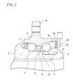
- FIG. 2 is an enlarged view of an essential part of FIG. 1 .
- the pulser ring 31 is mounted to a core 20 fitted on an outer periphery of the inner ring member 5, so as to be rotated unitarily with the inner ring 10 about an axis thereof.
- the pulser ring 31 has an annular shape wherein S-polarity and N-polarity alternate with each other in a circumferential direction.
- the pulser ring 31 employs an elastic material, such as rubber, which is admixed with ferromagnetic powder such as ferrite powder.
- the core 20 is formed from steel and serves dual purposes of supporting the pulser ring 31 and mounting the pulser ring 31 to the inner ring member 5.
- the steel constituting the core 20 is magnetized such that the pulser ring 31 may produce stronger magnetic field and magnetic flux.
- a rotor 30 including the core 20 and the pulser ring 31, and the magnetic sensor 32 constitute a rotary encoder 33.
- the magnetic sensor 32 detects the changes of the magnetic flux from the pulser ring 31. Therefore, the pulser ring 31 may preferably have an increased volume to produce stronger magnetic field and magnetic flux. The increase or decrease of an axial gap between the pulser ring 31 and the magnetic sensor 32 prevents an exact detection of the number of revolutions of the pulser ring 31.
- the core 20 supporting the pulser ring 31 is required to be of higher strength.
- FIG. 3 is a sectional view showing the rotor 30 according to a first embodiment of the invention.
- a vehicular-outer side (the left-hand side) from the rotor 30 shown in FIG..3 means an axially inner side
- a vehicular-inner side (the right-hand side) means an axially outer side.
- the core 20 includes: a cylindrical portion 21 fitted on the inner ring member 5; and a mounting flange 22 extending radially outwardly from an axially inner end (vehicular-outer side) of the cylindrical portion 21.
- the pulser ring 31 is mounted to the mounting flange 22 at an axially outer side surface (vehicular-inner side) thereof.
- the mounting flange 22 is described in greater details. It is noted here that the axially inner end of the cylindrical portion 21 will be referred to as a first end 24 and an axially outer end will be referred to as a second end 25.
- the mounting flange 22 extends halfway from the first end 24 of the cylindrical portion 21 in a radially outward direction, bends back axially outwardly at an acute angle to a radially outward phantom line, and then extends radially outwardly.
- a curved protrusion 23 opening toward the second end 25 is constituted by the bent portion of the mounting flange 22 and a part of the cylindrical portion 21.
- the protrusion 23 is provided at a corner portion between the cylindrical portion 21 and the mounting flange 22, protruding to the opposite side (from the first end 24 of the cylindrical portion 21) from the second end 25 of the cylindrical portion 21, and is opened toward the second end 25 thereof.
- a part of the pulser ring 31 is received by the overall inner space (opening side) of the protrusion 23.
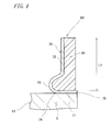
- FIG. 4 is a sectional view showing a rotor 80 according to a second embodiment of the invention.
- a core 70 includes: a cylindrical portion 71 fitted on the inner ring member 5; and a mounting flange 72 extending radially outwardly from an axially inner end (the left-hand side in FIG. 4 ; the vehicular-outer side) of the cylindrical portion 71.
- a pulser ring 81 is mounted to the mounting flange 72 at an axially outer side surface (the right-hand side in FIG. 4 ; the vehicular-inner side) thereof.
- a protrusion 73 is defined by a curved surface having an elliptical section.
- a radially inner portion of the mounting flange 72 is defined by a curved surface having a semi-elliptic section, which extends somewhat from a vehicular-outer end (a first end) 74 of the cylindrical portion 71 in an axially inward direction of the inner ring 5 along a curved line and further extends axially outwardly from some midpoint.
- the protrusion 73 protrudes to the opposite side from a second end 75 of the cylindrical portion 71 and is opened toward the second end 75. A part of the pulser ring 81 is received by the overall inner space (opening side) of the protrusion 73.
- the pulser ring 31, 81 may be formed not only from a mixture of an elastic material (elastomer), such as rubber, and ferrite powder, but also from a mixture of a synthetic resin (plastomer) and magnetic powder, such as ferrite powder.
- a so-called cure adhesion method may be used for mounting the pulser ring 31, 81 to the core 20, 70.
- the pulser ring 31, 81 is previously formed to have a sectional shape conforming to the shape of the core 20, 70.
- the pulser ring 31, 81 is temporarily fixed to the core 20, 70 by means of an adhesive. Subsequently, the adhesive is heated so that the pulser ring is completely secured to the core.
- the pulser ring 31, 81 may be insert molded by setting the core 20, 70 in a mold, followed by filling the mixture of synthetic resin and magnetic powder in the mold.
- the protrusion 23, 73 is provided at the corner portion formed between the cylindrical portion 21, 71 and the mounting flange 22, 72 such that the pulser ring 31, 81 may be partially received in the protrusion 23, 73. Therefore, the pulser ring 31, 81 may be increased in volume despite a small radial dimension thereof.
- the rotor 30, 80 is constructed which is capable of producing the strong magnetic field and magnetic flux.
- the protrusion 23, 73 is distended, while the pulser ring 31, 81 is disposed in a manner that a part thereof fills up the overall inner space of the protrusion 23, 73.
- the rotor 30, 80 is increased in axial thickness at a proximal end portion thereof (a radially inner portion at which the rotor is mounted to the inner ring) so that the proximal end portion of the rotor 30, 80 is increased in rigidity. If an external force is applied to the mounting flange 22, 72 when the rotor 30, 80 is mounted to the inner ring, for example, axial tilting of the mounting flange 22, 72 may be reduced. Namely, the rotor 30, 80 may be increased in magnetic intensity and mechanical strength.
- the configuration of the protrusion may include any other curved surface such as of parabola.
- the section of the protrusion may not be defined by a so-called curved surface but may be defined by a polygonal surface including many bent portions.
- the section of the protrusion may be defined by a general square U-shape including a plurality of right angles (the whole body of the core having a semi-anastatic sectional shape).
- the mounting flange may be provided with a plurality of protrusions so that the whole body of the core may have a E-shaped section (capital sigma).
- the rotor 30 may be used with bearings of other types such as deep groove ball bearings and tapered roller bearings, and may be used not with the wheel rolling bearing assembly 1 but other rolling bearing assemblies such as for machine tools.
Landscapes
- Engineering & Computer Science (AREA)
- Mechanical Engineering (AREA)
- Physics & Mathematics (AREA)
- General Physics & Mathematics (AREA)
- General Engineering & Computer Science (AREA)
- Transmission And Conversion Of Sensor Element Output (AREA)
- Rolling Contact Bearings (AREA)
Abstract
Description
- The present invention relates to a rotor for use in rotary encoder and a wheel rolling bearing assembly including the same.
-
FIG. 5 is a sectional view showing a rotary encoder in a conventional wheel rolling bearing assembly. A wheel rollingbearing assembly 210 includes: anouter ring 210a fixed to a vehicle body via a knuckle (not shown); aninner ring 210b fixed to an axle shaft (not shown) mounted with a wheel (not shown); a plurality ofballs 210c as rolling elements interposed between theouter ring 210a and theinner ring 210b; and acage 210d formed with pocket portions at regular space intervals, the pocket portions receiving theballs 210c. - The rotary encoder for detecting the number of revolutions of the wheel rolling
bearing assembly 210 includes: arotor 220 fixed to the wheel rollingbearing assembly 210; and a rotation detection sensor S for magnetically detecting the rotation of therotor 220.
Therotor 220 is formed from rubber admixed with magnetic powder, such as ferrite powder, and in an annular shape. The rotor includes: amagnetized portion 222 circumferentially magnetized in alternating S-polarity and N-polarity; and anannular core portion 221 supporting themagnetized portion 222. - The
core portion 221 further includes: acylindrical portion 221a press-fitted on an outer periphery of ashoulder 210e of theinner ring 21 0b; and aflange portion 221 b extended radially outwardly from one axial end of thecylindrical portion 221a. Thecore portion 221 is formed in an L-shape in section.
Themagnetized portion 222 is fixed to a lateral side of theflange 221b so as to oppose a detecting portion of the rotation detection sensor S in an axial direction. - When the
rotor 220 so fixed to theinner ring 210b is rotated in conjunction with the rotation of the wheel, the polarities of themagnetized portion 222 opposite the rotation detection sensor S alternate with each other, so that the rotation detection sensor S outputs the changes of magnetic field as the number of revolutions of the wheel. - Patent Document 1:
- Japanese Unexamined Patent Publication No.
2003-75194
- Japanese Unexamined Patent Publication No.
- The aforementioned
conventional rotor 220 has the following problems.
Therotor 220 is disposed in an annular space defined between theouter ring 210a and theinner ring 210b of the wheel rollingbearing assembly 210. Therefore, themagnetized portion 222 is limited in the radial dimension thereof so that the intensity of magnetic field produced by themagnetized portion 222 cannot be increased to a value of above a certain level. The increase of detection sensitivity of the rotary encoder dictates the need to increase the sensitivity of the rotation detection sensor S. Unfortunately, however, a high-sensitivity sensor is so expensive that a cost reduction of the rotary encoder is impracticable. - The
core portion 221 of therotor 220 is formed in a simple L-shape in section. Therefore, if the core portion is not formed in sufficient thickness, theflange 221b is prone to axial tilt. The axial tilt of theflange 221b leads to variations of the axial face-to-face distance between themagnetized portion 222 and the rotation detection sensor S. Therefore it is difficult to provide an exact detection of the number of revolutions. On the other hand, acore portion 221 with an increased thickness involves a difficult press working and increased manufacture cost results. - The invention has an object to provide a rotor for use in rotary encoder, which is adapted to produce a strong magnetic field without increasing the radial dimension of a pulser ring (magnetized portion) and to reduce tilting of the flange by achieving a greater strength of the core without increasing the thickness thereof, thereby achieving the exact rotation speed detection, as well as to provide a wheel rolling bearing assembly using the same.
- In accordance with the invention, a rotor for use in a rotary encoder comprises: a pulser ring magnetized in a manner that N polarity and S polarity appear alternately along a circumferential direction thereof, and a core for mounting the pulser ring to an outer periphery of a rotary shaft, wherein the core includes: a cylindrical portion fitted on the outer periphery of the rotary shaft, and a mounting flange extending radially outwardly from one axial end of the cylindrical portion, the mounting flange being mounted with the pulser ring.
The rotor is characterized in that a corner portion formed between the cylindrical portion and the mounting flange constitutes a protrusion unitized with the cylindrical portion and the mounting flange, protruding from the one axial end of the cylindrical portion and opened toward the other axial end thereof, and a part of the pulser ring is disposed in the protrusion. - This constitution permits the pulser ring limited in its radial length to attain a greater cross-sectional area than that of the conventional pulser ring. This leads to the construction of a rotor which is capable of producing a strong magnetic field.
- The protrusion is so formed as to protrude from the one axial end of the cylindrical portion and to receive a part of the pulser ring therein. Therefore, the mounting flange is increased in rigidity at a proximal end thereof so that axial tilting of the mounting flange may be reduced.
- The above rotor may be used, for example, in a wheel rolling bearing assembly. In this case, the number of revolutions of the rotary shaft (wheel) may be detected if the rotor is mounted to the outer periphery of the inner ring constituting the rotary shaft and the magnetic sensor is disposed in opposing relation with the pulser ring of the rotor.
- The invention provides a rotor for use in a rotary encoder, which is adapted to produce a strong magnetic field despite the small radial dimension of the pulser ring and to reduce axial tilting of the mounting flange of the core in the axial direction of the rotary shaft, so as to achieve an exact detection of the rotation speed.
-
-
FIG. 1 is a vertical sectional view showing a wheel rolling bearing assembly; -
FIG. 2 is an enlarged view of an essential part ofFIG. 1 ; -
FIG..3 3 is a sectional view showing a rotor according to a first embodiment of the invention; -
FIG. 4 is a sectional view showing a rotor according to a second embodiment of the invention; and -
FIG. 5 is a sectional view showing a conventional rotor. -
- 1 = Wheel Rolling Bearing Assembly
- 2 = Flanged axle shaft
- 3 = Shaft body
- 4 = Flange
- 5 = Inner ring member
- 6 = Outer ring
- 7 = Rolling element
- 10 = Inner ring
- 20, 70 = Core
- 21,71 = Cylindrical portion
- 22, 72 = Mounting flange
- 23,73 = Protrusion
- 24, 74 = First end portion (axial one end)
- 2.5, 75 = Second end portion (axial other end)
- 30, 80 = Rotor
- 31,81 = Pulser ring
- 32, 82 = Magnetic sensor
- 33 = Rotary encoder
- An embodiment of the invention will hereinbelow be described with reference to the accompanying drawings.
FIG. 1 is a vertical sectional view showing a wheel rollingbearing assembly 1. It is noted that the left-hand side as seen inFIG. 1 means a vehicular outer side whereas the right-hand side means a vehicular inner side. The same applies to the presentations inFIG. 2 to FIG. 4 .
The wheel rollingbearing assembly 1 has a basic construction as shown inFIG. 1 . Ashaft body 3 unitarily rotatable with a wheel is formed with aflange 4 at one axial end thereof, so that theshaft body 3 and theflange 4 jointly constitute aflanged axle shaft 2. Theflange 4 is formed with through-holes 11 at circumferential places thereof. Abrake disk rotor 6 is fixed to theflange 4 at a vehicular-outer side surface thereof by means ofbolts 14 press-inserted through the through-holes 11.
A wheel (not shown) is fixed to a vehicular-outer side of thebrake disk rotor 6 by means of thebolts 14. Adrive shaft 12 is fitted in an inner periphery of theshaft body 3 so that theshaft body 3 and thedrive shaft 12 are unitized by means of anut 13. - A diametrically greater
outside periphery 3b of theshaft body 3 defines a single inner raceway surface. Aninner ring member 5 having a single inner raceway surface is fitted on a diametrically smalleroutside periphery 3a of theshaft body 3. Theshaft body 3 and theinner ring member 5 fitted on theshaft body 3 jointly constitute aninner ring 10 defining a rotary shaft. An outer periphery side of theinner ring 10 is embraced by a fixed sideouter ring 6. Theouter ring 6 includes double-row outer ring raceway surfaces in correspondence to the two rows of raceway surfaces of theinner ring 10.
The raceway surfaces of theinner ring 10, the raceway surfaces of theouter ring 6, the rollingelements 7 arranged in double rows and twocages portion 15 of the wheel rollingbearing assembly 1. The bearingportion 15 is a double-row angular contact ball bearing. - A fixing
flange 16 projects radially outwardly from an outer periphery of theouter ring 6 so as to fix the outer ring to aknuckle 18 of a vehicle body. Further, aseal member 17 is interposed between a vehicular-outer end of theouter ring 6 and theflange 4. Theseal member 17 prevents muddy water and the like from invading into the bearing. Mounted to theknuckle 18 is amagnetic sensor 32 for detecting any changes of a magnetic flux from a pulser ring (magnetized portion) 31 in the form of pulses. -
FIG. 2 is an enlarged view of an essential part ofFIG. 1 . As shown inFIG. 2 , thepulser ring 31 is mounted to a core 20 fitted on an outer periphery of theinner ring member 5, so as to be rotated unitarily with theinner ring 10 about an axis thereof.
Thepulser ring 31 has an annular shape wherein S-polarity and N-polarity alternate with each other in a circumferential direction. Thepulser ring 31 employs an elastic material, such as rubber, which is admixed with ferromagnetic powder such as ferrite powder. Thecore 20 is formed from steel and serves dual purposes of supporting thepulser ring 31 and mounting thepulser ring 31 to theinner ring member 5. The steel constituting thecore 20 is magnetized such that thepulser ring 31 may produce stronger magnetic field and magnetic flux. - A
rotor 30 including thecore 20 and thepulser ring 31, and themagnetic sensor 32 constitute arotary encoder 33. As described above, themagnetic sensor 32 detects the changes of the magnetic flux from thepulser ring 31. Therefore, thepulser ring 31 may preferably have an increased volume to produce stronger magnetic field and magnetic flux. The increase or decrease of an axial gap between thepulser ring 31 and themagnetic sensor 32 prevents an exact detection of the number of revolutions of thepulser ring 31. Hence, the core 20 supporting thepulser ring 31 is required to be of higher strength. -
FIG. 3 is a sectional view showing therotor 30 according to a first embodiment of the invention. When looking on the bearing portion 15 (FIG. 1 ) of the rollingbearing assembly 1, a vehicular-outer side (the left-hand side) from therotor 30 shown inFIG..3 means an axially inner side, whereas a vehicular-inner side (the right-hand side) means an axially outer side.
Thecore 20 includes: acylindrical portion 21 fitted on theinner ring member 5; and a mountingflange 22 extending radially outwardly from an axially inner end (vehicular-outer side) of thecylindrical portion 21. Thepulser ring 31 is mounted to the mountingflange 22 at an axially outer side surface (vehicular-inner side) thereof. - The mounting
flange 22 is described in greater details. It is noted here that the axially inner end of thecylindrical portion 21 will be referred to as afirst end 24 and an axially outer end will be referred to as asecond end 25. The mountingflange 22 extends halfway from thefirst end 24 of thecylindrical portion 21 in a radially outward direction, bends back axially outwardly at an acute angle to a radially outward phantom line, and then extends radially outwardly. Acurved protrusion 23 opening toward thesecond end 25 is constituted by the bent portion of the mountingflange 22 and a part of thecylindrical portion 21.
Specifically, theprotrusion 23 is provided at a corner portion between thecylindrical portion 21 and the mountingflange 22, protruding to the opposite side (from thefirst end 24 of the cylindrical portion 21) from thesecond end 25 of thecylindrical portion 21, and is opened toward thesecond end 25 thereof. A part of thepulser ring 31 is received by the overall inner space (opening side) of theprotrusion 23. -
FIG. 4 is a sectional view showing arotor 80 according to a second embodiment of the invention.
In this embodiment, as well, acore 70 includes: acylindrical portion 71 fitted on theinner ring member 5; and a mountingflange 72 extending radially outwardly from an axially inner end (the left-hand side inFIG. 4 ; the vehicular-outer side) of thecylindrical portion 71. Apulser ring 81 is mounted to the mountingflange 72 at an axially outer side surface (the right-hand side inFIG. 4 ; the vehicular-inner side) thereof.
According to the second embodiment, aprotrusion 73 is defined by a curved surface having an elliptical section. Specifically, a radially inner portion of the mountingflange 72 is defined by a curved surface having a semi-elliptic section, which extends somewhat from a vehicular-outer end (a first end) 74 of thecylindrical portion 71 in an axially inward direction of theinner ring 5 along a curved line and further extends axially outwardly from some midpoint. According the second embodiment, as well, theprotrusion 73 protrudes to the opposite side from asecond end 75 of thecylindrical portion 71 and is opened toward thesecond end 75. A part of thepulser ring 81 is received by the overall inner space (opening side) of theprotrusion 73. - According to the first and second embodiments, the
pulser ring
A so-called cure adhesion method may be used for mounting thepulser ring core pulser ring pulser ring core
In a case where the synthetic resin is used instead of the rubber, thepulser ring core - As described above, the
protrusion cylindrical portion flange pulser ring protrusion pulser ring rotor
Theprotrusion pulser ring protrusion rotor rotor flange rotor flange
Namely, therotor - The invention is not limited to the foregoing embodiments and may also be practiced in other modifications and exemplary application modes.
For instance, the configuration of the protrusion may include any other curved surface such as of parabola. In this case, the section of the protrusion may not be defined by a so-called curved surface but may be defined by a polygonal surface including many bent portions. For instance, the section of the protrusion may be defined by a general square U-shape including a plurality of right angles (the whole body of the core having a semi-anastatic sectional shape).
Further, the mounting flange may be provided with a plurality of protrusions so that the whole body of the core may have a E-shaped section (capital sigma). - It is apparent that the
rotor 30 may be used with bearings of other types such as deep groove ball bearings and tapered roller bearings, and may be used not with the wheel rollingbearing assembly 1 but other rolling bearing assemblies such as for machine tools.
Claims (2)
- A rotor for use in a rotary encoder comprising:a pulser ring magnetized in a manner that N-polarity and S-polarity appear alternately along a circumferential direction thereof, and a core for mounting the pulser ring to an outer periphery of a rotary shaft, wherein the core includes:a cylindrical portion fitted on the outer periphery of the rotary shaft, and a mounting flange extending radially outwardly from one axial end of the cylindrical portion, wherein the mounting flange is mounted with the pulser ring,wherein a corner portion formed between the cylindrical portion and the mounting flange constitutes a protrusion unitized with the cylindrical portion and the mounting flange, protruding from the one axial end of the cylindrical portion and opened toward the other axial end thereof, wherein a part of the pulser ring is disposed in the protrusion.
- A wheel rolling bearing assembly comprising:an inner ring defining a rotary shaft, a fixed outer ring embracing an outer periphery of the inner ring, a rolling element rollably interposed between the inner ring and the outer ring,wherein the rotor according to Claim 1 is mounted to the outer periphery of the rotary shaft, and a magnetic sensor is disposed in opposing relation with the pulser ring of the rotor for detecting changes of a magnetic flux in the form of pulses.
Applications Claiming Priority (2)
| Application Number | Priority Date | Filing Date | Title |
|---|---|---|---|
| JP2006013441 | 2006-01-23 | ||
| PCT/JP2007/050805 WO2007083750A1 (en) | 2006-01-23 | 2007-01-19 | Rotor for rotary encoder and rolling bearing for wheel having same |
Publications (3)
| Publication Number | Publication Date |
|---|---|
| EP1983306A1 true EP1983306A1 (en) | 2008-10-22 |
| EP1983306A4 EP1983306A4 (en) | 2010-10-13 |
| EP1983306B1 EP1983306B1 (en) | 2014-04-02 |
Family
ID=38287700
Family Applications (1)
| Application Number | Title | Priority Date | Filing Date |
|---|---|---|---|
| EP07707093.6A Not-in-force EP1983306B1 (en) | 2006-01-23 | 2007-01-19 | Rotor for rotary encoder and rolling bearing for wheel having same |
Country Status (5)
| Country | Link |
|---|---|
| US (1) | US8096710B2 (en) |
| EP (1) | EP1983306B1 (en) |
| JP (1) | JP4840368B2 (en) |
| CN (1) | CN101371106B (en) |
| WO (1) | WO2007083750A1 (en) |
Families Citing this family (1)
| Publication number | Priority date | Publication date | Assignee | Title |
|---|---|---|---|---|
| JP7294976B2 (en) * | 2019-09-30 | 2023-06-20 | ファナック株式会社 | motor |
Family Cites Families (17)
| Publication number | Priority date | Publication date | Assignee | Title |
|---|---|---|---|---|
| FR2642122B1 (en) * | 1989-01-20 | 1991-04-05 | Roulements Soc Nouvelle | ROTATING SEAL WITH INTEGRATED MAGNETIC ENCODER, PARTICULARLY FOR BEARINGS WITH INFORMATION SENSORS |
| IT1237618B (en) * | 1989-12-15 | 1993-06-08 | Roberto Moretti | DEVICE SUITABLE FOR ALLOWING THE DETECTION OF THE ROTATION SPEED BETWEEN TWO BODIES IN RELATIVE ROTATION SUCH AS THE SUPPORT BODIES OF A WHEEL OF A VEHICLE. |
| FR2700588B1 (en) * | 1993-01-19 | 1995-02-17 | Roulements Soc Nouvelle | Mounting device with integrated encoder seal. |
| FR2730283B1 (en) * | 1995-02-03 | 1997-03-21 | Roulements Soc Nouvelle | SEAL WITH INCORPORATED ENCODER, EQUIPPED WITH AN INFORMATION SENSOR DEVICE, FOR BEARING OR BEARING |
| US5947611A (en) * | 1996-01-22 | 1999-09-07 | Nsk Ltd. | Rolling bearing unit with tone wheel |
| DE19644744C2 (en) * | 1996-10-28 | 2002-05-02 | Fag Automobiltechnik Ag | Speed measuring device for wheel bearings |
| ITTO980210A1 (en) * | 1998-03-12 | 1999-09-12 | Skf Ind Spa | SEALING DEVICE FOR A ROLLING BEARING |
| JP2000289405A (en) * | 1999-04-02 | 2000-10-17 | Nsk Ltd | Combination seal ring with encoder |
| JP4141588B2 (en) * | 1999-06-02 | 2008-08-27 | 株式会社ジェイテクト | Wheel speed detection device |
| JP4014359B2 (en) * | 2000-12-06 | 2007-11-28 | Ntn株式会社 | Bearing with rotation sensor and motor using the same |
| JP2003075194A (en) | 2001-09-03 | 2003-03-12 | Koyo Seiko Co Ltd | Method of magnetizing pulser ring |
| US6789948B2 (en) | 2001-09-25 | 2004-09-14 | Ntn Corporation | Magnetic encoder and wheel bearing assembly using the same |
| EP1469239B1 (en) * | 2003-04-17 | 2007-11-07 | Ntn Corporation | A bearing for a wheel of vehicle |
| JP2004354102A (en) | 2003-05-27 | 2004-12-16 | Nsk Ltd | Encoder and rolling bearing unit with encoder |
| JP4318205B2 (en) * | 2003-06-23 | 2009-08-19 | Ntn株式会社 | Rolling bearing for wheel and bearing device for semi-floating wheel provided with the same |
| JP4417080B2 (en) | 2003-11-28 | 2010-02-17 | 富士重工業株式会社 | Encoder seal structure |
| JP2005331429A (en) * | 2004-05-21 | 2005-12-02 | Ntn Corp | Rolling bearing unit with encoder |
-
2007
- 2007-01-19 EP EP07707093.6A patent/EP1983306B1/en not_active Not-in-force
- 2007-01-19 US US12/087,342 patent/US8096710B2/en not_active Expired - Fee Related
- 2007-01-19 JP JP2007554979A patent/JP4840368B2/en not_active Expired - Fee Related
- 2007-01-19 WO PCT/JP2007/050805 patent/WO2007083750A1/en not_active Ceased
- 2007-01-19 CN CN2007800027445A patent/CN101371106B/en not_active Expired - Fee Related
Also Published As
| Publication number | Publication date |
|---|---|
| JPWO2007083750A1 (en) | 2009-06-11 |
| CN101371106A (en) | 2009-02-18 |
| JP4840368B2 (en) | 2011-12-21 |
| EP1983306A4 (en) | 2010-10-13 |
| WO2007083750A1 (en) | 2007-07-26 |
| US20090003744A1 (en) | 2009-01-01 |
| CN101371106B (en) | 2010-12-15 |
| EP1983306B1 (en) | 2014-04-02 |
| US8096710B2 (en) | 2012-01-17 |
Similar Documents
| Publication | Publication Date | Title |
|---|---|---|
| US10099509B2 (en) | Wheel bearing apparatus incorporated with a wheel speed detecting apparatus | |
| CN100497974C (en) | Rolling bearing unit with rotating speed-detecting device | |
| US6109793A (en) | Rolling bearing unit with rotational speed sensor | |
| CN106030137A (en) | Rolling bearing unit having rotation speed detector device | |
| US5938346A (en) | Rolling bearing unit with rotating speed sensor | |
| JP2004354299A (en) | Bearing device with built-in rotating speed sensor | |
| WO2017150562A1 (en) | Bearing device for vehicle wheel | |
| JP3497351B2 (en) | Rolling bearing unit with encoder | |
| JP2003013982A (en) | Bearing unit with encoder | |
| EP1983306B1 (en) | Rotor for rotary encoder and rolling bearing for wheel having same | |
| JP2011252552A (en) | Bearing device for wheel | |
| JP2016078512A (en) | Bearing device for wheel | |
| JP4260055B2 (en) | Wheel bearing device | |
| JP2006275200A (en) | Cover for rolling bearing device and rolling bearing device using the same | |
| CN101646946A (en) | Sensor holder and wheel bearing device integrated with it and equipped with rotational speed detection device | |
| JP4245249B2 (en) | Bearing device | |
| JP2006064145A (en) | Bearing device for wheel | |
| KR102636950B1 (en) | Encoder ring and wheel bearing provided therewith | |
| JP4803572B2 (en) | Magnetic encoder and wheel bearing device provided with the same | |
| JP2005076696A (en) | Rolling bearing device | |
| JP5213464B2 (en) | Wheel bearing device with rotation speed detector | |
| JP4675063B2 (en) | Wheel bearing device with rotation sensor | |
| JP2024085273A (en) | Wheel bearing device | |
| JP6852265B2 (en) | Hub unit | |
| JP6394051B2 (en) | Rolling bearing unit with rotational speed detector |
Legal Events
| Date | Code | Title | Description |
|---|---|---|---|
| PUAI | Public reference made under article 153(3) epc to a published international application that has entered the european phase |
Free format text: ORIGINAL CODE: 0009012 |
|
| 17P | Request for examination filed |
Effective date: 20080822 |
|
| AK | Designated contracting states |
Kind code of ref document: A1 Designated state(s): DE FR |
|
| RBV | Designated contracting states (corrected) |
Designated state(s): DE FR |
|
| A4 | Supplementary search report drawn up and despatched |
Effective date: 20100915 |
|
| DAX | Request for extension of the european patent (deleted) | ||
| GRAP | Despatch of communication of intention to grant a patent |
Free format text: ORIGINAL CODE: EPIDOSNIGR1 |
|
| INTG | Intention to grant announced |
Effective date: 20131021 |
|
| RIN1 | Information on inventor provided before grant (corrected) |
Inventor name: TAKADA, YOSHITO |
|
| GRAS | Grant fee paid |
Free format text: ORIGINAL CODE: EPIDOSNIGR3 |
|
| GRAA | (expected) grant |
Free format text: ORIGINAL CODE: 0009210 |
|
| AK | Designated contracting states |
Kind code of ref document: B1 Designated state(s): DE FR |
|
| REG | Reference to a national code |
Ref country code: DE Ref legal event code: R096 Ref document number: 602007035873 Country of ref document: DE Effective date: 20140515 |
|
| REG | Reference to a national code |
Ref country code: DE Ref legal event code: R097 Ref document number: 602007035873 Country of ref document: DE |
|
| REG | Reference to a national code |
Ref country code: FR Ref legal event code: PLFP Year of fee payment: 9 |
|
| PLBE | No opposition filed within time limit |
Free format text: ORIGINAL CODE: 0009261 |
|
| STAA | Information on the status of an ep patent application or granted ep patent |
Free format text: STATUS: NO OPPOSITION FILED WITHIN TIME LIMIT |
|
| 26N | No opposition filed |
Effective date: 20150106 |
|
| REG | Reference to a national code |
Ref country code: DE Ref legal event code: R097 Ref document number: 602007035873 Country of ref document: DE Effective date: 20150106 |
|
| PGFP | Annual fee paid to national office [announced via postgrant information from national office to epo] |
Ref country code: FR Payment date: 20150108 Year of fee payment: 9 |
|
| REG | Reference to a national code |
Ref country code: FR Ref legal event code: ST Effective date: 20160930 |
|
| PG25 | Lapsed in a contracting state [announced via postgrant information from national office to epo] |
Ref country code: FR Free format text: LAPSE BECAUSE OF NON-PAYMENT OF DUE FEES Effective date: 20160201 |
|
| PGFP | Annual fee paid to national office [announced via postgrant information from national office to epo] |
Ref country code: DE Payment date: 20221130 Year of fee payment: 17 |
|
| REG | Reference to a national code |
Ref country code: DE Ref legal event code: R119 Ref document number: 602007035873 Country of ref document: DE |
|
| PG25 | Lapsed in a contracting state [announced via postgrant information from national office to epo] |
Ref country code: DE Free format text: LAPSE BECAUSE OF NON-PAYMENT OF DUE FEES Effective date: 20240801 |
|
| PG25 | Lapsed in a contracting state [announced via postgrant information from national office to epo] |
Ref country code: DE Free format text: LAPSE BECAUSE OF NON-PAYMENT OF DUE FEES Effective date: 20240801 |