EP1983209A2 - Integrated outboard wet disk brake - Google Patents
Integrated outboard wet disk brake Download PDFInfo
- Publication number
- EP1983209A2 EP1983209A2 EP08103402A EP08103402A EP1983209A2 EP 1983209 A2 EP1983209 A2 EP 1983209A2 EP 08103402 A EP08103402 A EP 08103402A EP 08103402 A EP08103402 A EP 08103402A EP 1983209 A2 EP1983209 A2 EP 1983209A2
- Authority
- EP
- European Patent Office
- Prior art keywords
- disk brake
- wet disk
- integrated
- outboard
- several
- Prior art date
- Legal status (The legal status is an assumption and is not a legal conclusion. Google has not performed a legal analysis and makes no representation as to the accuracy of the status listed.)
- Withdrawn
Links
- 239000000725 suspension Substances 0.000 claims abstract description 17
- 238000005266 casting Methods 0.000 claims abstract description 5
- 239000006096 absorbing agent Substances 0.000 claims description 6
- 230000035939 shock Effects 0.000 claims description 6
- 239000012809 cooling fluid Substances 0.000 abstract description 4
- 239000012530 fluid Substances 0.000 description 5
- 238000011109 contamination Methods 0.000 description 2
- 230000001627 detrimental effect Effects 0.000 description 1
- 230000017525 heat dissipation Effects 0.000 description 1
- 238000004519 manufacturing process Methods 0.000 description 1
- 230000004048 modification Effects 0.000 description 1
- 238000012986 modification Methods 0.000 description 1
- 239000002689 soil Substances 0.000 description 1
- 238000005728 strengthening Methods 0.000 description 1
- XLYOFNOQVPJJNP-UHFFFAOYSA-N water Substances O XLYOFNOQVPJJNP-UHFFFAOYSA-N 0.000 description 1
Images

Classifications
-
- F—MECHANICAL ENGINEERING; LIGHTING; HEATING; WEAPONS; BLASTING
- F16—ENGINEERING ELEMENTS AND UNITS; GENERAL MEASURES FOR PRODUCING AND MAINTAINING EFFECTIVE FUNCTIONING OF MACHINES OR INSTALLATIONS; THERMAL INSULATION IN GENERAL
- F16D—COUPLINGS FOR TRANSMITTING ROTATION; CLUTCHES; BRAKES
- F16D55/00—Brakes with substantially-radial braking surfaces pressed together in axial direction, e.g. disc brakes
- F16D55/02—Brakes with substantially-radial braking surfaces pressed together in axial direction, e.g. disc brakes with axially-movable discs or pads pressed against axially-located rotating members
- F16D55/22—Brakes with substantially-radial braking surfaces pressed together in axial direction, e.g. disc brakes with axially-movable discs or pads pressed against axially-located rotating members by clamping an axially-located rotating disc between movable braking members, e.g. movable brake discs or brake pads
-
- F—MECHANICAL ENGINEERING; LIGHTING; HEATING; WEAPONS; BLASTING
- F16—ENGINEERING ELEMENTS AND UNITS; GENERAL MEASURES FOR PRODUCING AND MAINTAINING EFFECTIVE FUNCTIONING OF MACHINES OR INSTALLATIONS; THERMAL INSULATION IN GENERAL
- F16D—COUPLINGS FOR TRANSMITTING ROTATION; CLUTCHES; BRAKES
- F16D55/00—Brakes with substantially-radial braking surfaces pressed together in axial direction, e.g. disc brakes
- F16D2055/0004—Parts or details of disc brakes
- F16D2055/0008—Brake supports
- F16D2055/0012—Brake supports integral with vehicle suspension
Definitions
- This invention relates generally to brakes on utility vehicles that are used for off-road, recreational or agricultural work.
- a wet disk brake is needed for a utility vehicle having reduced cost and lower weight of the brake enclosure.
- a wet disk brake is needed that minimizes or reduces any increase in the unsprung mass of a utility vehicle.
- a wet disk brake is needed that does not require strengthening the halfshafts.
- An integrated outboard wet disk brake is provided for use with an off-road utility vehicle having independent wheel suspension.
- the integrated outboard wet disk brake may be a one piece casting having upper and lower portions pivotably attached to a control arm or other independent wheel suspension component, and a power plate providing a backing surface for a sealed annular housing.
- the integrated outboard wet disk brake provides a low cost assembly that uses fewer parts and fewer manufacturing tool requirements than non-integrated wet disk brake and support components.
- the integrated outboard wet disk brake minimizes or reduces any increase in the unsprung mass of a utility vehicle.
- the integrated outboard wet disk brake is cast as a monolithic structure in which the sealed annular housing can serve as part of the vehicle suspension. The unsprung mass of the vehicle is reduced by using the sealed annular housing to carry the suspension loads.
- integrated wet disk brake 100 is a one-piece, monolithic casting including upper and lower portions 102, 104 extending from power plate 106.
- the upper and lower portions of the integrated wet disk brake may be connected to a utility vehicle's independent front wheel suspension, and the power plate may be part of sealed annular housing 108.
- the upper and lower portions of the integrated wet disk brake provide the only support structure between the independent front wheel suspension and the front wheel of the vehicle.
- the upper and lower portions 102, 104 of the integrated wet disk brake may be connected to the independent front wheel suspension components for a front wheel of a utility vehicle, which may be shock absorber 116, coil spring 118 and lower control arm 126.
- Upper portion 102 of the integrated wet disk brake extends radially and axially from power plate 106 above central opening 109 of sealed annular housing 108, which is the axis of rotation for a front axle half shaft and hub.
- Upper portion 102 may include sleeve 114 where the lower ends of shock absorber 116 and coil spring 118 may be mounted, and also may include joint 120 for pivotable attachment to a steering linkage (not shown).
- the lower portion of the integrated wet disk brake extends radially and axially from power plate 106 below central opening 109 of sealed annular housing 108, and below a front axle half shaft and hub.
- Lower portion 104 may include seat 122 where ball joint 124 may be mounted. The ball joint may be connected to the outer end of lower control arm 126. The inner end of the lower control arm may be pivotably mounted to the vehicle chassis.
- Lower portion 104 of the integrated wet disk brake also may include stop 128 which can abut the lower control arm to block turning beyond a maximum steering angle.
- Anti-sway bar 130 may be attached between the left and right control arms by links 132.
- power plate 106 provides a backing surface for sealed annular housing 108 where stators and rotors may be alternately positioned in a chamber between the power plate and cover 138.
- the rotors may be splined to the inner diameter of the hub.
- sealed annular housing 108 may enclose brake cooling fluid introduced through a fill plug in cover 138.
- the front disk brakes may be actuated by pressurized brake fluid into a brake hose connector through power plate 106.
- Internal passages or ducts in the power plate may direct brake fluid from the brake hose connector to an annular piston in sealed annular housing 108, which can move in response to the pressure to urge the stators and rotors into frictional contact.
- Bleed screw 146 may be provided in a bleed passage in the power plate to remove air from the system.
- a front wheel may be mounted by threaded studs or other fasteners to flange 152.
- a hub 112 may be inserted through central opening 109 in the sealed annular housing, and engaged by splines to a half shaft.
- Annular seals may be provided between the hub or half shaft and cover 138, and/or between the hub or half shaft and power plate 106.
- Ball bearings also may be provided between the hub or half shaft and cover 138, and/or between the hub or half shaft and power plate 106.
- integrated wet disk brake 200 is a one-piece casting including upper and lower portions 202, 204 extending from power plate 206.
- the upper and lower portions may be connected to a utility vehicle's independent rear wheel suspension, and power plate 206 may be a part of sealed annular housing 208.
- the upper and lower portions may provide the only support structure between the independent rear wheel suspension and a rear wheel of a vehicle.
- upper and lower portions 202, 204 of the integrated wet disk brake may be pivotably connected to upper and lower control arms 214, 216 which may be the components of an independent rear wheel suspension for a rear wheel of a utility vehicle.
- Upper portion 202 of the integrated wet disk brake extends radially and axially from power plate 206 above central opening 209 in sealed annular housing 208, which is the axis of rotation for a rear axle half shaft and hub.
- Outer end 215 of upper control arm 214 may be pivotably mounted to upper portion 202 by pivot connection 217 through sleeve 230 in the upper portion of the integrated wet disk brake.
- the inner end 219 of upper control arm 214 may be pivotably mounted to the vehicle chassis.
- Shock absorber 216 and coil spring 218 also may be mounted between bracket 221 on upper control arm 214 and the vehicle chassis.
- lower portion 204 of integrated wet disk brake 200 may extend radially and axially from power plate 206 below central opening 209 in sealed annular housing 208, below the rear axle half shaft and hub, and may be pivotably connected to the outer end of lower control arm 216.
- Outer end 223 of lower control arm 216 may be pivotably mounted to lower portion 204 by pivot connection 225 through sleeve 231 in the lower portion of the integrated wet disk brake.
- Inner ends 227 of lower control arm 216 may be pivotably mounted to the vehicle chassis.
- power plate 206 provides a backing surface for sealed annular housing 208 where stators and rotors may be alternately positioned in a chamber between the power plate and cover 238.
- the rotors may be splined to the inner diameter of the hub.
- sealed annular housing 208 may enclose brake cooling fluid introduced through a fill plug in cover 238.
- the rear disk brakes may be actuated by pressurized brake fluid into a brake hose connector in power plate 206.
- Internal passages or ducts in the power plate may direct brake fluid from the brake hose connector to an annular piston, which can move in response to the pressure to urge the stators and rotors into frictional contact.
- Bleeder screw 246 may be provided in a bleed passage in and through the power plate to remove air from the system.
- a rear wheel may be mounted by threaded studs or other fasteners to flange 252.
- a hub may be inserted into central opening 209 in the sealed annular housing, and engaged by splines to a half shaft.
- Annular seals may be provided between the hub or half shaft and cover 238, and/or between the hub or half shaft and power plate 206.
- Ball bearings may be provided between the hub or half shaft and cover 238, and/or between the hub or half shaft and power plate 206.
Landscapes
- Engineering & Computer Science (AREA)
- General Engineering & Computer Science (AREA)
- Mechanical Engineering (AREA)
- Braking Arrangements (AREA)
Abstract
Description
- This invention relates generally to brakes on utility vehicles that are used for off-road, recreational or agricultural work.
- Brakes on automotive vehicles convert kinetic energy of vehicle motion into friction and heat to slow or stop the vehicle. Dry disk brakes may be exposed to the atmosphere to dissipate the heat. As a result, dry disk brakes are subject to contamination from soil, water and other debris, especially on utility vehicles that are frequently driven off-road.
- The problems of contamination and heat dissipation can be addressed by encasing the brakes and running them in a fluid bath of brake cooling fluid. However, wet disk brakes have the disadvantages of greater cost and higher weight of the brake enclosure. If the enclosed brake is mounted at the vehicle's wheels, the unsprung mass of the vehicle increases. This is undesirable because it is detrimental to vehicle ride and handling. Additionally, if the brake is mounted inboard, the halfshafts must be made stronger to handle the braking loads.
- A wet disk brake is needed for a utility vehicle having reduced cost and lower weight of the brake enclosure. A wet disk brake is needed that minimizes or reduces any increase in the unsprung mass of a utility vehicle. A wet disk brake is needed that does not require strengthening the halfshafts.
- It is therefore the object of the present invention to comply with one, some or all of these needs.
- This object is met according to the invention by the teaching of claim 1, while features developing the solution in an advantageous manner are set forth in the further claims.
- An integrated outboard wet disk brake is provided for use with an off-road utility vehicle having independent wheel suspension. The integrated outboard wet disk brake may be a one piece casting having upper and lower portions pivotably attached to a control arm or other independent wheel suspension component, and a power plate providing a backing surface for a sealed annular housing.
- The integrated outboard wet disk brake provides a low cost assembly that uses fewer parts and fewer manufacturing tool requirements than non-integrated wet disk brake and support components. The integrated outboard wet disk brake minimizes or reduces any increase in the unsprung mass of a utility vehicle. The integrated outboard wet disk brake is cast as a monolithic structure in which the sealed annular housing can serve as part of the vehicle suspension. The unsprung mass of the vehicle is reduced by using the sealed annular housing to carry the suspension loads.
- An embodiment of the invention described below is shown in the drawings, in which:
-
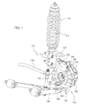
Fig. 1 is a perspective view of a front wheel suspension with an integrated outboard wet disk brake according to a first embodiment of the invention. -
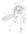
Fig. 2 is a perspective view of an integrated outboard wet disk brake according to a first embodiment of the invention. -
Fig. 3 is a perspective view of a rear wheel suspension with an integrated outboard wet disk brake according to a second embodiment of the invention. -
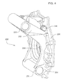
Fig. 4 is a perspective view of an integrated outboard wet disk brake according to a second embodiment of the invention. - In a first embodiment shown in
Figs. 1 and2 , integratedwet disk brake 100 is a one-piece, monolithic casting including upper andlower portions power plate 106. The upper and lower portions of the integrated wet disk brake may be connected to a utility vehicle's independent front wheel suspension, and the power plate may be part of sealedannular housing 108. The upper and lower portions of the integrated wet disk brake provide the only support structure between the independent front wheel suspension and the front wheel of the vehicle. - In a first embodiment, the upper and
lower portions coil spring 118 andlower control arm 126.Upper portion 102 of the integrated wet disk brake extends radially and axially frompower plate 106 abovecentral opening 109 of sealedannular housing 108, which is the axis of rotation for a front axle half shaft and hub.Upper portion 102 may includesleeve 114 where the lower ends of shock absorber 116 andcoil spring 118 may be mounted, and also may includejoint 120 for pivotable attachment to a steering linkage (not shown). - In one embodiment, the lower portion of the integrated wet disk brake extends radially and axially from
power plate 106 belowcentral opening 109 of sealedannular housing 108, and below a front axle half shaft and hub.Lower portion 104 may includeseat 122 whereball joint 124 may be mounted. The ball joint may be connected to the outer end oflower control arm 126. The inner end of the lower control arm may be pivotably mounted to the vehicle chassis.Lower portion 104 of the integrated wet disk brake also may includestop 128 which can abut the lower control arm to block turning beyond a maximum steering angle.Anti-sway bar 130 may be attached between the left and right control arms bylinks 132. - In a first embodiment,
power plate 106 provides a backing surface for sealedannular housing 108 where stators and rotors may be alternately positioned in a chamber between the power plate andcover 138. The rotors may be splined to the inner diameter of the hub. - In a first embodiment, sealed
annular housing 108 may enclose brake cooling fluid introduced through a fill plug incover 138. The front disk brakes may be actuated by pressurized brake fluid into a brake hose connector throughpower plate 106. Internal passages or ducts in the power plate may direct brake fluid from the brake hose connector to an annular piston in sealedannular housing 108, which can move in response to the pressure to urge the stators and rotors into frictional contact.Bleed screw 146 may be provided in a bleed passage in the power plate to remove air from the system. - In a first embodiment, a front wheel may be mounted by threaded studs or other fasteners to flange 152. A hub 112 may be inserted through
central opening 109 in the sealed annular housing, and engaged by splines to a half shaft. Annular seals may be provided between the hub or half shaft andcover 138, and/or between the hub or half shaft andpower plate 106. Ball bearings also may be provided between the hub or half shaft andcover 138, and/or between the hub or half shaft andpower plate 106. - In a second embodiment shown in
Figs. 3 and4 , integratedwet disk brake 200 is a one-piece casting including upper andlower portions power plate 206. The upper and lower portions may be connected to a utility vehicle's independent rear wheel suspension, andpower plate 206 may be a part of sealedannular housing 208. The upper and lower portions may provide the only support structure between the independent rear wheel suspension and a rear wheel of a vehicle. - In a second embodiment, upper and
lower portions lower control arms Upper portion 202 of the integrated wet disk brake extends radially and axially frompower plate 206 abovecentral opening 209 in sealedannular housing 208, which is the axis of rotation for a rear axle half shaft and hub.Outer end 215 ofupper control arm 214 may be pivotably mounted toupper portion 202 bypivot connection 217 throughsleeve 230 in the upper portion of the integrated wet disk brake. Theinner end 219 ofupper control arm 214 may be pivotably mounted to the vehicle chassis. Shock absorber 216 andcoil spring 218 also may be mounted betweenbracket 221 onupper control arm 214 and the vehicle chassis. - In one embodiment,
lower portion 204 of integratedwet disk brake 200 may extend radially and axially frompower plate 206 belowcentral opening 209 in sealedannular housing 208, below the rear axle half shaft and hub, and may be pivotably connected to the outer end oflower control arm 216.Outer end 223 oflower control arm 216 may be pivotably mounted tolower portion 204 bypivot connection 225 throughsleeve 231 in the lower portion of the integrated wet disk brake.Inner ends 227 oflower control arm 216 may be pivotably mounted to the vehicle chassis. - In the second embodiment,
power plate 206 provides a backing surface for sealedannular housing 208 where stators and rotors may be alternately positioned in a chamber between the power plate andcover 238. The rotors may be splined to the inner diameter of the hub. - In the second embodiment, sealed
annular housing 208 may enclose brake cooling fluid introduced through a fill plug incover 238. The rear disk brakes may be actuated by pressurized brake fluid into a brake hose connector inpower plate 206. Internal passages or ducts in the power plate may direct brake fluid from the brake hose connector to an annular piston, which can move in response to the pressure to urge the stators and rotors into frictional contact.Bleeder screw 246 may be provided in a bleed passage in and through the power plate to remove air from the system. - In the second embodiment, a rear wheel may be mounted by threaded studs or other fasteners to
flange 252. A hub may be inserted intocentral opening 209 in the sealed annular housing, and engaged by splines to a half shaft. Annular seals may be provided between the hub or half shaft and cover 238, and/or between the hub or half shaft andpower plate 206. Ball bearings may be provided between the hub or half shaft and cover 238, and/or between the hub or half shaft andpower plate 206. - Having described preferred embodiments, it will become apparent that various modifications can be made without departing from the scope of the invention as defined in the accompanying claims.
Claims (14)
- An integrated outboard wet disk brake (100, 200) characterized by a monolithic structure including a power plate (106, 206), and upper and lower portions (102, 202, 104, 204) extending from the power plate (106, 206), the power plate (106, 206) providing a backing surface for a sealed annular housing (108, 208) and the upper and lower portions (102, 202, 104, 204) providing the only support structure between an independent wheel supension and a wheel.
- The integrated outboard wet disk brake for claim 1, characterized in that the independent wheel suspension includes a shock absorber (116, 216) and a coil spring (118, 218).
- The integrated outboard wet disk brake according to claim 1 or 2, characterized in that the upper portion (102, 202) includes a sleeve (114 230) where a first component of the independent wheel suspension is mounted.
- The integrated outboard wet disk brake according to one or several of the previous claims, characterized in that the upper portion is preferably pivotably connected to a/the shock absorber (116, 216) and coil spring (118, 218), wherein the upper portion (102,202) preferably includes a sleeve (114, 230) where the shock absorber (116, 216) and coil spring (118, 218) are mounted.
- The integrated outboard wet disk according to one or several of the previous claims, characterized in that the upper portion (102, 202) further includes a joint (120) pivotably connected to a steering linkage.
- The integrated outboard wet disk brake according to one or several of the previous claims, characterized in that the independent wheel suspension includes a pivotable control arm (126, 214, 216), preferably having an inner end pivotably attached to a vehicle frame.
- The integrated outboard wet disk brake according to one or several of the previous claims, characterized in that the upper portion (102, 202) is pivotably connected to an outer end of a/the control arm (126, 214, 216) and/or that the lower portion (104, 204) is pivotably connected to an outer end of a/the control arm (126, 214, 216).
- The integrated outboard wet disk brake according to one or several of the previous claims, characterized in that the lower portion (104, 204) is pivotably attached to the outer end of a/the control arm (126, 214, 216), wherein the upper portion (102, 202) is preferably connected to an outer end of a second control arm (126, 214, 216).
- The integrated outboard wet disk brake according to one or several of the claims 6 to 8, characterized by a ball joint (124) connecting the lower portion to the outer end of the control arm (126, 214, 216).
- The integrated outboard wet disk brake according to one or several of the previous claims, characterized in by a cover (128, 238) attached to the power plate (106, 206) to form the sealed annular housing (108, 208).
- The integrated outboard wet disk brake according to one or several of the previous claims, characterized in that the upper portion (102, 202) and lower portion (104 204) each extend radially and axially from the power plate (106, 206).
- The integrated outboard wet disk brake, characterized in that the monolithic structure is a one-piece casting
- The integrated outboard wet disk brake according to one or several of the previous claims, characterized by a central opening (109, 209) in the sealed annular housing (108, 208), wherein the upper portion (102, 202) preferably is above the central opening (109, 209), and the lower portion (104, 204) is below the central opening (109, 209).
- The integrated outboard wet disk brake according to one or several of the previous claims, characterized in that the lower portion (104, 204) includes a stop (128) which can abut the control arm (126, 214, 216) to block turning beyond a maximum steering angle.
Applications Claiming Priority (1)
| Application Number | Priority Date | Filing Date | Title |
|---|---|---|---|
| US11/737,775 US8256583B2 (en) | 2007-04-20 | 2007-04-20 | Integrated outboard wet disk brake |
Publications (2)
| Publication Number | Publication Date |
|---|---|
| EP1983209A2 true EP1983209A2 (en) | 2008-10-22 |
| EP1983209A3 EP1983209A3 (en) | 2010-07-21 |
Family
ID=39707971
Family Applications (1)
| Application Number | Title | Priority Date | Filing Date |
|---|---|---|---|
| EP08103402A Withdrawn EP1983209A3 (en) | 2007-04-20 | 2008-04-07 | Integrated outboard wet disk brake |
Country Status (2)
| Country | Link |
|---|---|
| US (1) | US8256583B2 (en) |
| EP (1) | EP1983209A3 (en) |
Families Citing this family (1)
| Publication number | Priority date | Publication date | Assignee | Title |
|---|---|---|---|---|
| DE102009023418B4 (en) | 2009-05-29 | 2019-06-19 | Knorr-Bremse Systeme für Nutzfahrzeuge GmbH | Arrangement of a braking device on a steerable wheel axle of a vehicle |
Citations (2)
| Publication number | Priority date | Publication date | Assignee | Title |
|---|---|---|---|---|
| EP0402777A1 (en) | 1989-06-13 | 1990-12-19 | Toyota Jidosha Kabushiki Kaisha | Suspension for steerable driving wheel in vehicle |
| DE19611427A1 (en) | 1995-03-23 | 1996-09-26 | Dana Corp | Steered axle for motor vehicles |
Family Cites Families (8)
| Publication number | Priority date | Publication date | Assignee | Title |
|---|---|---|---|---|
| US4128145A (en) * | 1977-08-31 | 1978-12-05 | Lambert Brake Corporation | Combination failsafe brake and one-way clutch |
| US4753455A (en) * | 1986-07-15 | 1988-06-28 | Nissasn Motor Co., Ltd. | Double link type suspension system |
| KR0131299B1 (en) * | 1992-12-28 | 1998-04-21 | 전성원 | Steering wheel suspension |
| SE509788C2 (en) * | 1997-07-18 | 1999-03-08 | Volvo Constr Equip Components | Planetary gear for a vehicle wheel |
| JP3894627B2 (en) * | 1997-09-11 | 2007-03-22 | 本田技研工業株式会社 | Multi-plate brake for vehicles |
| DE10204975B4 (en) * | 2001-02-12 | 2006-05-11 | The Pullman Co., Milan | swivel |
| SE523652C2 (en) * | 2001-11-08 | 2004-05-04 | Volvo Constr Equip Components | Annular means for a braking device and a device for driving a wheel of a vehicle comprising said annular means |
| US7083176B2 (en) * | 2004-01-06 | 2006-08-01 | General Motors Corporation | Wheel alignment arrangements for vehicles |
-
2007
- 2007-04-20 US US11/737,775 patent/US8256583B2/en active Active
-
2008
- 2008-04-07 EP EP08103402A patent/EP1983209A3/en not_active Withdrawn
Patent Citations (2)
| Publication number | Priority date | Publication date | Assignee | Title |
|---|---|---|---|---|
| EP0402777A1 (en) | 1989-06-13 | 1990-12-19 | Toyota Jidosha Kabushiki Kaisha | Suspension for steerable driving wheel in vehicle |
| DE19611427A1 (en) | 1995-03-23 | 1996-09-26 | Dana Corp | Steered axle for motor vehicles |
Also Published As
| Publication number | Publication date |
|---|---|
| US8256583B2 (en) | 2012-09-04 |
| EP1983209A3 (en) | 2010-07-21 |
| US20080257659A1 (en) | 2008-10-23 |
Similar Documents
| Publication | Publication Date | Title |
|---|---|---|
| JP4052569B2 (en) | Suspension arm mounting structure | |
| JP6046450B2 (en) | Aluminum steering knuckle | |
| CN101410266B (en) | Grounding Structures for Vehicles | |
| US5878479A (en) | Method of forming a cross vented rotor and an initial casting for forming a vented rotor | |
| US11821476B2 (en) | Disc brake caliper body | |
| EP3087291B1 (en) | Disc brake caliper body and disc brake caliper | |
| US7845473B2 (en) | Brake caliper structure of straddle seat off-road vehicle | |
| JPH08159178A (en) | Vehicle brakes | |
| US20060049006A1 (en) | Seat mount structure for saddle ride type vehicle | |
| US8256583B2 (en) | Integrated outboard wet disk brake | |
| MXPA02005816A (en) | Adapter plate for disc brake installation. | |
| CN113771554A (en) | A drive axle assembly with main reducer parking structure | |
| CN107458211B (en) | A kind of electronic wheel assembly | |
| JP2007195320A (en) | In-wheel motor system | |
| CA2578476A1 (en) | Mounting structure of speed reduction device and brake device of vehicle | |
| JPH05193513A (en) | Steering device | |
| JP2007191035A (en) | In-wheel motor system | |
| WO2022009046A1 (en) | Caliper body and brake caliper with said body | |
| JP3609108B2 (en) | Servo brakes for vehicles | |
| CN201089510Y (en) | Rear-wheel hydraulic disc type breaking mechanism for minitype scooter | |
| KR20060095123A (en) | Axle assembly of drive wheel | |
| CN212373345U (en) | Disc brake bent axle | |
| JP2004156694A (en) | Brake disc structure | |
| JP2819187B2 (en) | Disc brake device for railway vehicles | |
| CN119953106A (en) | A hybrid drive rear axle structure |
Legal Events
| Date | Code | Title | Description |
|---|---|---|---|
| PUAI | Public reference made under article 153(3) epc to a published international application that has entered the european phase |
Free format text: ORIGINAL CODE: 0009012 |
|
| AK | Designated contracting states |
Kind code of ref document: A2 Designated state(s): AT BE BG CH CY CZ DE DK EE ES FI FR GB GR HR HU IE IS IT LI LT LU LV MC MT NL NO PL PT RO SE SI SK TR |
|
| AX | Request for extension of the european patent |
Extension state: AL BA MK RS |
|
| PUAL | Search report despatched |
Free format text: ORIGINAL CODE: 0009013 |
|
| AK | Designated contracting states |
Kind code of ref document: A3 Designated state(s): AT BE BG CH CY CZ DE DK EE ES FI FR GB GR HR HU IE IS IT LI LT LU LV MC MT NL NO PL PT RO SE SI SK TR |
|
| AX | Request for extension of the european patent |
Extension state: AL BA MK RS |
|
| 17P | Request for examination filed |
Effective date: 20110121 |
|
| AKX | Designation fees paid |
Designated state(s): DE GB |
|
| 17Q | First examination report despatched |
Effective date: 20150921 |
|
| STAA | Information on the status of an ep patent application or granted ep patent |
Free format text: STATUS: THE APPLICATION IS DEEMED TO BE WITHDRAWN |
|
| 18D | Application deemed to be withdrawn |
Effective date: 20170919 |