EP1983189A1 - Eco-run control device and method for resetting the same - Google Patents
Eco-run control device and method for resetting the same Download PDFInfo
- Publication number
- EP1983189A1 EP1983189A1 EP08154509A EP08154509A EP1983189A1 EP 1983189 A1 EP1983189 A1 EP 1983189A1 EP 08154509 A EP08154509 A EP 08154509A EP 08154509 A EP08154509 A EP 08154509A EP 1983189 A1 EP1983189 A1 EP 1983189A1
- Authority
- EP
- European Patent Office
- Prior art keywords
- eco
- engine
- run
- state
- control device
- Prior art date
- Legal status (The legal status is an assumption and is not a legal conclusion. Google has not performed a legal analysis and makes no representation as to the accuracy of the status listed.)
- Granted
Links
Images



Classifications
-
- F—MECHANICAL ENGINEERING; LIGHTING; HEATING; WEAPONS; BLASTING
- F02—COMBUSTION ENGINES; HOT-GAS OR COMBUSTION-PRODUCT ENGINE PLANTS
- F02N—STARTING OF COMBUSTION ENGINES; STARTING AIDS FOR SUCH ENGINES, NOT OTHERWISE PROVIDED FOR
- F02N11/00—Starting of engines by means of electric motors
- F02N11/08—Circuits specially adapted for starting of engines
- F02N11/0814—Circuits specially adapted for starting of engines comprising means for controlling automatic idle-start-stop
- F02N11/0818—Conditions for starting or stopping the engine or for deactivating the idle-start-stop mode
-
- F—MECHANICAL ENGINEERING; LIGHTING; HEATING; WEAPONS; BLASTING
- F02—COMBUSTION ENGINES; HOT-GAS OR COMBUSTION-PRODUCT ENGINE PLANTS
- F02D—CONTROLLING COMBUSTION ENGINES
- F02D41/00—Electrical control of supply of combustible mixture or its constituents
- F02D41/24—Electrical control of supply of combustible mixture or its constituents characterised by the use of digital means
- F02D41/26—Electrical control of supply of combustible mixture or its constituents characterised by the use of digital means using computer, e.g. microprocessor
- F02D41/266—Electrical control of supply of combustible mixture or its constituents characterised by the use of digital means using computer, e.g. microprocessor the computer being backed-up or assisted by another circuit, e.g. analogue
-
- F—MECHANICAL ENGINEERING; LIGHTING; HEATING; WEAPONS; BLASTING
- F02—COMBUSTION ENGINES; HOT-GAS OR COMBUSTION-PRODUCT ENGINE PLANTS
- F02D—CONTROLLING COMBUSTION ENGINES
- F02D41/00—Electrical control of supply of combustible mixture or its constituents
- F02D41/02—Circuit arrangements for generating control signals
- F02D41/04—Introducing corrections for particular operating conditions
- F02D41/042—Introducing corrections for particular operating conditions for stopping the engine
-
- F—MECHANICAL ENGINEERING; LIGHTING; HEATING; WEAPONS; BLASTING
- F02—COMBUSTION ENGINES; HOT-GAS OR COMBUSTION-PRODUCT ENGINE PLANTS
- F02D—CONTROLLING COMBUSTION ENGINES
- F02D41/00—Electrical control of supply of combustible mixture or its constituents
- F02D41/24—Electrical control of supply of combustible mixture or its constituents characterised by the use of digital means
- F02D41/2406—Electrical control of supply of combustible mixture or its constituents characterised by the use of digital means using essentially read only memories
- F02D41/2425—Particular ways of programming the data
- F02D41/2487—Methods for rewriting
- F02D41/2493—Resetting of data to a predefined set of values
-
- F—MECHANICAL ENGINEERING; LIGHTING; HEATING; WEAPONS; BLASTING
- F02—COMBUSTION ENGINES; HOT-GAS OR COMBUSTION-PRODUCT ENGINE PLANTS
- F02N—STARTING OF COMBUSTION ENGINES; STARTING AIDS FOR SUCH ENGINES, NOT OTHERWISE PROVIDED FOR
- F02N11/00—Starting of engines by means of electric motors
- F02N11/10—Safety devices
-
- F—MECHANICAL ENGINEERING; LIGHTING; HEATING; WEAPONS; BLASTING
- F02—COMBUSTION ENGINES; HOT-GAS OR COMBUSTION-PRODUCT ENGINE PLANTS
- F02N—STARTING OF COMBUSTION ENGINES; STARTING AIDS FOR SUCH ENGINES, NOT OTHERWISE PROVIDED FOR
- F02N2250/00—Problems related to engine starting or engine's starting apparatus
- F02N2250/02—Battery voltage drop at start, e.g. drops causing ECU reset
-
- F—MECHANICAL ENGINEERING; LIGHTING; HEATING; WEAPONS; BLASTING
- F02—COMBUSTION ENGINES; HOT-GAS OR COMBUSTION-PRODUCT ENGINE PLANTS
- F02N—STARTING OF COMBUSTION ENGINES; STARTING AIDS FOR SUCH ENGINES, NOT OTHERWISE PROVIDED FOR
- F02N2300/00—Control related aspects of engine starting
- F02N2300/30—Control related aspects of engine starting characterised by the use of digital means
-
- F—MECHANICAL ENGINEERING; LIGHTING; HEATING; WEAPONS; BLASTING
- F02—COMBUSTION ENGINES; HOT-GAS OR COMBUSTION-PRODUCT ENGINE PLANTS
- F02N—STARTING OF COMBUSTION ENGINES; STARTING AIDS FOR SUCH ENGINES, NOT OTHERWISE PROVIDED FOR
- F02N2300/00—Control related aspects of engine starting
- F02N2300/30—Control related aspects of engine starting characterised by the use of digital means
- F02N2300/302—Control related aspects of engine starting characterised by the use of digital means using data communication
- F02N2300/304—Control related aspects of engine starting characterised by the use of digital means using data communication with other systems inside the vehicle
-
- F—MECHANICAL ENGINEERING; LIGHTING; HEATING; WEAPONS; BLASTING
- F02—COMBUSTION ENGINES; HOT-GAS OR COMBUSTION-PRODUCT ENGINE PLANTS
- F02P—IGNITION, OTHER THAN COMPRESSION IGNITION, FOR INTERNAL-COMBUSTION ENGINES; TESTING OF IGNITION TIMING IN COMPRESSION-IGNITION ENGINES
- F02P11/00—Safety means for electric spark ignition, not otherwise provided for
- F02P11/02—Preventing damage to engines or engine-driven gearing
- F02P11/025—Shortening the ignition when the engine is stopped
-
- Y—GENERAL TAGGING OF NEW TECHNOLOGICAL DEVELOPMENTS; GENERAL TAGGING OF CROSS-SECTIONAL TECHNOLOGIES SPANNING OVER SEVERAL SECTIONS OF THE IPC; TECHNICAL SUBJECTS COVERED BY FORMER USPC CROSS-REFERENCE ART COLLECTIONS [XRACs] AND DIGESTS
- Y02—TECHNOLOGIES OR APPLICATIONS FOR MITIGATION OR ADAPTATION AGAINST CLIMATE CHANGE
- Y02T—CLIMATE CHANGE MITIGATION TECHNOLOGIES RELATED TO TRANSPORTATION
- Y02T10/00—Road transport of goods or passengers
- Y02T10/10—Internal combustion engine [ICE] based vehicles
- Y02T10/40—Engine management systems
Definitions
- the present invention relates to an eco-run control device that has an eco-run function to drive a vehicle while starting and stopping the engine.
- An eco-run control device issues an engine stop instruction when predetermined engine stop requirements are satisfied, and later issues an engine restart instruction to drive an engine starting motor when predetermined engine start requirements are satisfied.
- An eco-run ECU that performs eco-run control operations determines whether to stop the engine and whether to start the engine, based on an eco-run allowing signal and an eco-run prohibiting signal transmitted from another ECU, and signals transmitted from various sensors and actuators.
- An eco-run ECU and most ECUs cooperating with the eco-run ECU form a so-called IG system, and power is supplied to the ECUs when the ignition switch is switched on.
- the IG system when the ignition key is turned off, the power supply to the ECU is cut off, and the ECUs are put into a reset state.
- data needs to be written in a nonvolatile memory in the eco-run ECU, and therefore, the eco-run ECU has a main relay so that an operation can be continued for a predetermined period of time (approximately 3 seconds) after the ignition key is turned off.
- the eco-run ECU When the driver switches the ignition key from an ON state to an OFF state to an ON state in a short period of time during an eco-run control operation, the eco-run ECU is not reset, but the other ECUs are reset. Therefore, the other ECUs transmit an eco-run prohibiting signal to the eco-run ECU when the ignition key is switched from an OFF state to an ON state.
- the eco-run ECU that has received the eco-run prohibiting signal drives the starter motor in accordance with the eco-run prohibiting signal.
- the starter driving is performed, with the switching of the ignition key from an OFF state to an ON state being a trigger.
- the starter driving is automatically started, even though the driver does not operate to turn on the starter motor. This makes the driver feel uneasy. In the worst case, the vehicle suddenly moves forward.
- the RAM in the eco-run ECU is pseudo-reset by software.
- the RAM is reset when the ignition key is in an OFF state and an interruption is detected in a communication of one of the ECUs communicating with the eco-run ECU.
- the ECUs that communicate with the eco-run ECU may be any ECUs among the ECUs connected to an IG line, the ECUs connected to an accessory power supply line, and the ECUs connected to a +B line.
- the IG line is the power supply line connected to the +-pole of the battery via the ignition switch.
- the accessory power supply line is the power supply line connected to the +-pole of the battery via an accessory switch.
- the +B line is the power supply line connected directly to the +-pole of the battery.
- Japanese Unexamined Patent Publication No. 2004-17676 discloses a technique by which a control device that is connected to a network and has an error is restarted and is put back into an initialized state when the error is caused.
- the eco-run ECU is reset when a communication between the eco-run ECU and an ECU connected to the +B line or the ACC line is interrupted.
- the IG switch is determined to be OFF due to an inadvertent key operation, when a communication with another ECU is interrupted due to disconnection or temporary disconnection of the IG line.
- the RAM of the eco-run ECU is reset, so as to prohibit the eco-run ECU from performing an engine start control operation, or to stop the engine.
- the compensation for a low voltage is 8 V or higher. Therefore, when the IG line is temporarily disconnected at the time of a low voltage, communications might become invalid. Accordingly, there is a possibility that the eco-run ECU is frequently reset when the voltage is low.
- Japanese Unexamined Patent Publication No. 2004-17676 does not disclose a method for determining whether the ignition switch is switched off by an operation of the ignition key or temporary disconnection of the IG line.
- a more specific object of the present invention is to provide an eco-run control device and a reset method by which eco-run control against a user's will is restricted.
- an eco-run control device that is mounted on a vehicle and is capable of performing eco-run control to stop an engine when predetermined stop requirements are satisfied and restart the engine when predetermined start requirements are satisfied later
- the eco-run control device including: a monitoring unit that monitors a state of an ignition; a communicating unit that communicates with a plurality of control devices that receive power supplies from a power supply line that is connected to a power source via the ignition; and an initialization controlling unit that initializes data with respect to the eco-run control stored in a memory, when the monitoring unit determines that the ignition is in an OFF state, and that the communications with two or more of the control devices are interrupted.
- an eco-run control device that is mounted on a vehicle and is capable of performing eco-run control to stop an engine when predetermined stop requirements are satisfied and restart the engine when predetermined start requirements are satisfied later
- the eco-run control device including: an engine start controlling unit that performs a start control operation on the engine, when receiving an eco-run prohibiting request from another control device mounted on the vehicle; and an engine start control prohibiting unit that prohibits the engine start controlling unit from performing the start control operation on the engine, when an ignition is in an OFF state and communications with two or more of other control devices are interrupted, the other control device having a power source switched on and off in accordance with the state of the ignition.
- an eco-run control device that is mounted on a vehicle and is capable of performing eco-run control to stop an engine when predetermined stop requirements are satisfied and restart the engine when predetermined start requirements are satisfied later
- the eco-run control device including: an engine state controlling unit that puts the engine into a started state, when receiving an eco-run prohibiting request from another control device mounted on the vehicle, the engine state controlling unit putting the engine into an stopped state even when receiving the eco-run prohibiting request, where an ignition is in an OFF state and communications with two or more of other control devices are interrupted, the other control device having a power source switched on and off in accordance with the state of the ignition.
- a method for resetting an eco-run control device including the steps of: determining that an ignition is in an OFF state with the use of a monitoring unit; determining a state of each communication with a plurality of control devices that receive a power supply from a power supply line that is connected to a power source via the ignition; and initializing data with respect to the eco-run control stored in a memory, when the monitoring unit determines that the communications with two or more of the control devices are interrupted.
- an eco-run ECU (this eco-run ECU includes the initialization controller, the engine start controller, the engine start control prohibiting unit, and the engine state controller of the present invention) 1 and nodes are connected to a CAN (Controller Area Network) bus 31.
- a CAN Controller Area Network
- an engine ECU 2 a steering ECU 3, an air conditioner ECU 4, a navigation ECU 5, a vehicle stability control ECU (hereinafter referred to as VSC ECU) 6, a yaw rate G sensor 7, a meter ECU 8, a body ECU 9, and an air bag ECU 10 are shown as the nodes that perform CAN communications with the eco-run ECU 1.
- the nodes are not limited to those nodes.
- Each of the nodes receives a power supply from a battery 11 to operate.
- the eco-run ECU 1, the meter ECU 8, the body ECU 9, and the air bag ECU 10 are connected to a +B line 32 that is connected directly to the +-pole of the battery 11.
- the engine ECU 2, the VSC ECU 6, the yaw rate G sensor 7, and the likes are connected to an IG line 33 that is connected to the +-pole of the battery 11 via an ignition switch (hereinafter referred to as the IG switch) 27.
- the air conditioner ECU 4, the navigation ECU 5, and the likes are connected to an accessory source line 34 that is connected to the +-pole of the battery 11 via an accessory switch (hereinafter referred to the ACC switch) 28.
- the engine ECU 2 is connected to an EFI (Electronic Fuel Injection) that electronically controls the amount of fuel injection to the engine.
- EFI Electronic Fuel Injection
- the engine ECU 2 controls engine outputs, and adjusts the driving speed.
- the steering ECU 3 electronically controls the steering angle of the steering unit that steers the front wheels, so as to adjust the driving direction of the vehicle.
- the air conditioner ECU 4 is connected to an operation unit (not shown) that is designed to set the temperature of a vehicle air-conditioning device (not shown) and selects an air outlet or the like. Based on the detected values of an ambient temperature sensor (not shown), an inside temperature sensor (not shown), and an insolation sensor (not shown), the air conditioner ECU 4 performs various control operations in accordance with the settings of the operation unit and the likes.
- the navigation ECU 5 When the position of a destination is input through an operation switch (not shown), the navigation ECU 5 automatically selects the optimum route from the current location of the vehicle to the destination, and calculates a guide route. The navigation ECU 5 then causes a display device (not shown) to display route guide information.
- the VSC ECU 6 Based on information that is supplied from an acceleration sensor or a vehicle speed sensor (not shown) or the like, the VSC ECU 6 sends an instruction to the engine ECU 2 to restrict engine outputs, or sends an instruction to a brake actuator (not shown) to control the vehicle speed and stabilize the position of the vehicle.
- the yaw rate G sensor 7 is formed with a yaw rate sensor and a G sensor.
- the yaw rate sensor detects the angular velocity (hereinafter referred to as the yaw rate) around the axis line (the rolling axis) passing through the center of gravity of the vehicle and extending forward and backward from the vehicle.
- the G sensor includes a front-back G sensor that detects the acceleration in the front-back direction of the vehicle, and a transverse G sensor that detects the acceleration in the transverse direction of the vehicle.
- the meter ECU 8 receives detection signals from various sensors (not shown), and performs various operations. By doing so, the meter ECU 8 generates outputs for displaying the vehicle traveling speed, the engine speed, the shift position, the remaining amount of fuel, and the water temperature.
- the body ECU 9 controls vehicle-mounted mechanisms such as a door lock mechanism or a power window mechanism.
- the air bag ECU 10 activates an air bag, when a G sensor (not shown) senses a collision of the vehicle.
- Each of the above described ECUs transmits an eco-run prohibition signal to the eco-run ECH 1, when the ECU is activated by switching the IG switch from an OFF state to an ON state or the like.
- the eco-run ECU 1 also has an input terminal for inputting signals from various sensors, an output terminal for switching on and off a switch, and the likes.
- the eco-run ECU 1 further includes: a terminal for inputting a sensor signal from a voltage sensor 12 that detects the voltage of the battery 11; a terminal that monitors the state of an eco-run cancel switch 13 for canceling an eco-run; an IG switch monitoring terminal that monitors the switching on and off of the IG switch 27; a terminal that monitors the power generating state of an alternator (a generator) 14; a vehicle speed input terminal; a terminal that detects the oil pressure with an oil pressure switch 15 provided on an oil passage; a terminal that inputs a signal from a hood switch 16 that outputs signals in accordance with the open/closed states of the front hood and the rear hood of the vehicle; a terminal that outputs a driving signal to a motor IC 17 that controls the driving of an electric pump; a terminal that monitors the driving of the electric pump; a user SW terminal that detects an operation of a select switch 18 by the driver; and a terminal that receives the engine speed from the engine ECU 2.
- the eco-run ECU 1 also has a detecting unit that detects starting operations such as a shift operation, a brake operation, and a clutch operation performed by the driver.
- Detection of a shift operation is performed by the eco-run ECU 1 receiving and judging information supplied from a shift position sensor that detects the operation position of a shift lever (not shown) through the engine ECU 2.
- Detection of a brake operation is performed by the eco-run ECU 1 receiving and judging information supplied from a brake master cylinder pressure sensor (not shown) through a brake ECU (not shown).
- Detection of a clutch operation is performed by the eco-run ECU 1 inputting a signal from a clutch upper switch 26.
- the eco-run ECU 1 also automatically starts the engine, when an engine starting factor (such as a vehicle error, a negative pressure release, or a start request from any other ECU) other than the above driver's starting operations is detected.
- an engine starting factor such as a vehicle error, a negative pressure release, or a start request from any other ECU
- the eco-run ECU 1 when receiving an eco-run prohibiting signal from some other ECU, the eco-run ECU 1 performs a control operation such as driving of a starter motor 20, so as to put the engine into an activated state.
- the starter motor 20 is connected to the +B line 32 that supplies power from the battery 11.
- a starter relay 21 is turned on by connecting the starter relay 21 to a coil 22, the power from the battery 11 is supplied to the starter motor 20.
- the starter motor 20 is activated, the engine is started.
- the starter relay 21 is also connected to the eco-run ECU 1.
- the starter relay 21 is turned on by a control signal transmitted from the eco-run ECU 1, so that the engine can be started by the starter motor 20.
- a nonvolatile memory 25 connected to the eco-run ECU 1 stores processing programs and the likes to be used for controlling the eco-run ECU 1.
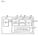
- Fig. 2 illustrates the structure of the eco-run ECU 1.
- the eco-run ECU 1 includes a combined IC 40 and a microcomputer 50.
- the combined IC 40 controls the power supply to the microcomputer 50.
- the microcomputer 50 includes: a central processing unit (CPU) 51 that performs various operations in accordance with programs; a ROM 52 that is a read-only memory that stores the processing program and the likes to be executed by the CPU 51; a RAM 53 that is a readable and rewritable memory that has a work area to be used in the various processing operations performed by the CPU 51, and a data storage area that stores various kinds of data; and a data input/output port (shown as "I/O" in the drawing) 54.
- CPU central processing unit
- ROM 52 that is a read-only memory that stores the processing program and the likes to be executed by the CPU 51
- RAM 53 that is a readable and rewritable memory that has a work area to be used in the various processing operations performed by the CPU 51, and a data storage area that stores various kinds of data
- a data input/output port shown as "I/O" in the drawing
- the programs to be realized by the microcomputer 50 performing operations in accordance with programs read from the ROM 52 are an eco-run control application 61, a diagnosis application 62, a communication application 63, and platform software 64 shown in Fig. 2 .
- the eco-run control application 61 is an application for eco-run control operations. When predetermined requirements for an engine stop are satisfied, the eco-run control application 61 instructs the engine ECU 2 to stop the engine, so as to stop idling of the engine. When the requirements for an engine start are satisfied after that, the eco-run control application 61 instructs the engine ECU 2 to restart the engine. Under control of the engine ECU 2, the starter motor is driven to start the engine.
- the diagnosis application 62 determines diagnosis codes and recovery processes in accordance with the diagnosis codes as the specifications.
- the diagnosis application 62 creates a self-diagnosing program to perform operations in accordance with the specifications, and incorporates the program into the ROM or the like.
- the CPU then executes this program. If a hardware error is detected, the CPU writes the diagnosis code corresponding to the type of the error into the memory, and carries out the error recovery process corresponding to the diagnosis code.
- the communication application 63 performs communications with nodes such as the other ECU and sensors connected by a communication line in accordance with the CAN protocol.
- the state of the monitor signal is changed from an IG switch OFF state to an IG switch ON state, when the IG switch 27 is switched from an OFF state to an ON state by the driver operating the ignition key, or when a signal line 30 that monitors the state of the IG switch 27 is temporarily disconnected.
- the eco-run ECU 1 determines whether the IG switch 27 is switched on and off by a driver's operation or temporary disconnection of the signal line 30.
- the variables recorded in the RAM of the eco-run ECU 1 are reset only when the IG switch 27 is switched from an OFF state to an ON state by an operation performed by the driver.
- the eco-run ECU 1 determines that the IG switch 27 is switched from an OFF state to an ON state by an operation performed by the driver, when the state of the monitor signal is put into an IG switch OFF state and the communications with two or more of the nodes connected to the IG line 33 are interrupted.
- the eco-run ECU 1 monitors CAN communications to determine whether the IG switch 27 is switched off.
- the IG switch 27 When the state of the monitor signal is switched from an IG switch OFF state to an IG switch ON state by temporarily disconnecting the signal line 30 that monitors the IG line 33, the IG switch 27 might be ON. Accordingly, data is transmitted from the nodes connected to the IG line 33 via CAN communications.
- driver's operations or information supplied from the navigation ECU 5 can be referred to.
- the information may be a signal indicating the position of the shift lever, a signal indicating the vehicle speed, a signal indicating the engine speed, a signal indicating that the foot brake is stepped on, a signal indicating that a door is opened or closed, and the likes.
- a navigation destination and the current location information about the vehicle may be input from the navigation ECU 5, and switching on and off of the IG switch 27 may be detected based on the information.
- the communication application 63 has a communication interruption determining counter for each of the nodes connected to the IG line 33, and monitors the state of a communication with each node, based on the count value.
- the communication application 63 When receiving data from the engine ECU 2 ("YES" in step S1), the communication application 63 initializes the communication interruption determining counter for the engine ECU (step S2). If there is no data received from the engine ECU 2 ("NO" in step S1), the communication application 63 compares the count value of the communication interruption determining counter for the engine ECU with the reference value for determining a communication interruption (step S3). If the count value is equal to or larger than the reference value (“YES" in step S3), the communication application 63 determines that the communication with the engine ECU 2 is in an interrupted state (step S4).
- the communication application 63 determines whether there is data received from the steering ECU 3 (step S5). If there is data received from the steering ECU 3 ("YES” in step S5), the communication application 63 initializes the communication interruption determining counter for the steering ECU 3 (step S6). If there is no data received from the steering ECU 3 ("NO” in step S5), the communication application 63 compares the count value of the communication interruption determining counter for the steering ECU 3 with the reference value for determining a communication interruption (step S7). If the count value is equal to or larger than the reference value (“YES" in step S7), the communication application 63 determines that the communication with the steering ECU 3 is in an interrupted state (step S8).
- the communication application 63 determines whether there is data received from the yaw rate G sensor 7 (step S9). If there is data received from the yaw rate G sensor 7 ("YES" in step S9), the communication application 63 initializes the communication interruption determining counter for the yaw rate G sensor 7 (step S10). If there is no data received from the yaw rate G sensor 7 ("NO” in step S9), the communication application 63 compares the count value of the communication interruption determining counter for the yaw rate G sensor 7 with the reference value for determining a communication interruption (step S11). If the count value is equal to or larger than the reference value ("YES" in step S11), the communication application 63 determines that the communication with the yaw rate G sensor 7 is in an interrupted state (step S12).
- the communication application 63 determines whether there is data received from the VSC ECU 6 (step S13). If there is data received from the VSC ECU 6 ("YES" in step S13), the communication application 63 initializes the communication interruption determining counter for the VSC ECU 6 (step S14). If there is no data received from the VSC ECU 6 ("NO” in step S13), the communication application 63 compares the count value of the communication interruption determining counter for the VSC ECU 6 with the reference value for determining a communication interruption (step S15). If the count value is equal to or larger than the reference value (“YES" in step S15), the communication application 63 determines that the communication with the VSC ECU 6 is in an interrupted state (step S16).
- the data to be used for determining whether there is a communication interruption may be a frame that is transmitted at the shortest interval among the frames transmitted from the subject node. In this manner, the time required for determining whether there is a communication interruption can be shortened.
- the nodes that are connected to the IG line 33 and require a long time to determine whether there is a communication interruption may be excluded from the nodes for determining a communication interruption. Also, the nodes that have long intervals for communications with the eco-run ECU 1 also require a long time for determining a communication interruption, and may be excluded from the communication interruption determining operation.
- step S21 When a signal from the IG switch monitor terminal is a signal indicating an IG switch OFF state ("YES" in step S21), the eco-run ECU 1 determines whether the communications with the nodes connected to the IG line 33 are interrupted (step S22).
- This communication interruption determining procedures have already been described with reference to the flowchart shown in Fig. 3 , and therefore, explanation of them is omitted here.
- the eco-run ECU 1 determines whether the communications with two or more nodes are in an interrupted state. For example, if the communications with two or more nodes are in an interrupted state ("YES" in step S23), the eco-run ECU 1 puts an initialization determination flag into an ON state (step S24). If the communication with less than two node is in an interrupted state ("NO" in step S23), the eco-run ECU 1 puts the initialization determination flag into an OFF state (step S25).
- the eco-run ECU 1 determines whether the IG switch 27 is switched from an OFF state to an ON state (step S26). More specifically, the eco-run ECU 1 determines whether the signal of the monitor terminal that monitors the state of the IG switch 27 is switched from an IG switch off state to an IG switch ON state before the power supply to the eco-run ECU 1 is stopped (step S26). If there is not a change in the state of the signal of the monitor terminal ("NO" in step S26), the eco-run ECU 1 determines whether the signal of the monitor terminal remains in an IG switch OFF state (step S28).
- the eco-run ECU 1 determines whether there is an initializing operation (step S29).
- the initialization history indicates the previous value of the initialization determination flag. When the initialization determination flag is ON, the initialization history shows that there is a record. When the initialization determination flag is OFF, the initialization history shows that there is not a record.
- step S23 referring to the initialization determination flag, the eco-run ECU 1 writes the result of the initialization determination on the initialization history.
- step S26 determines whether the signal that is input to the monitor terminal is switched from an IG switch OFF state to an IG switch ON state. If the signal of the monitor terminal is switched from an IG switch OFF state to an IG switch ON sate ("YES" in step S26), the eco-run ECU 1 determines whether there is a recorded history of an initializing operation (step S27). It there is a recorded history of an initializing operation ("YES" in step S27), the eco-run ECU 1 carries out a pseudo-reset procedure (step S30). In the pseudo-reset procedure, the variables with respect to eco-run control recorded in the RAM in the eco-run ECU 1 are reset.
- step S30 the pseudo-reset procedure is carried out (step S30) when there is a recorded history of an initializing operation ("YES" in step S29).
- the monitor signal is switched from an ON state to an OFF state to an ON state during a short period of time. Accordingly, no interruptions are detected from the communications with the other nodes connected to the IG line 33 during the short period of time.
- the signal line 30 for monitoring the IG line 33 is temporarily disconnected, a history of an initializing operation is not recorded, and the pseudo-reset procedure is not carried out.
- the eco-run ECU 1 can accurately determine whether the IG switch 27 is switched on and off by a driver's operation or temporary disconnection of the signal line 30. Accordingly, the variables recorded in the RAM in the eco-run ECU 1 can be reset, only when the IG switch 27 is switched from an OFF state to an ON state by a driver's operation.
- eco-run control against the user's will be prohibited not only by resetting the variables (flags and variables stored in a temporary memory) with respect to eco-run control in the eco-run ECU 1, but also by software.
- the eco-run prohibiting signal may be masked and rejected until predetermined requirements are satisfied.
- the predetermined requirements include "a predetermined period of time has passed" and "an interrupted communication with an ECU is recovered".
Landscapes
- Engineering & Computer Science (AREA)
- General Engineering & Computer Science (AREA)
- Computer Hardware Design (AREA)
- Chemical & Material Sciences (AREA)
- Combustion & Propulsion (AREA)
- Mechanical Engineering (AREA)
- Microelectronics & Electronic Packaging (AREA)
- Control Of Vehicle Engines Or Engines For Specific Uses (AREA)
- Output Control And Ontrol Of Special Type Engine (AREA)
Abstract
Description
- The present invention relates to an eco-run control device that has an eco-run function to drive a vehicle while starting and stopping the engine.
- In recent years, to improve fuel efficiency and reduce emission, eco-run control devices are mounted on vehicles. An eco-run control device issues an engine stop instruction when predetermined engine stop requirements are satisfied, and later issues an engine restart instruction to drive an engine starting motor when predetermined engine start requirements are satisfied.
- An eco-run ECU that performs eco-run control operations determines whether to stop the engine and whether to start the engine, based on an eco-run allowing signal and an eco-run prohibiting signal transmitted from another ECU, and signals transmitted from various sensors and actuators.
- An eco-run ECU and most ECUs cooperating with the eco-run ECU form a so-called IG system, and power is supplied to the ECUs when the ignition switch is switched on. In the IG system, when the ignition key is turned off, the power supply to the ECU is cut off, and the ECUs are put into a reset state. However, data needs to be written in a nonvolatile memory in the eco-run ECU, and therefore, the eco-run ECU has a main relay so that an operation can be continued for a predetermined period of time (approximately 3 seconds) after the ignition key is turned off.
- When the driver switches the ignition key from an ON state to an OFF state to an ON state in a short period of time during an eco-run control operation, the eco-run ECU is not reset, but the other ECUs are reset. Therefore, the other ECUs transmit an eco-run prohibiting signal to the eco-run ECU when the ignition key is switched from an OFF state to an ON state.
- The eco-run ECU that has received the eco-run prohibiting signal drives the starter motor in accordance with the eco-run prohibiting signal. In other words, the starter driving is performed, with the switching of the ignition key from an OFF state to an ON state being a trigger. As a result, the starter driving is automatically started, even though the driver does not operate to turn on the starter motor. This makes the driver feel uneasy. In the worst case, the vehicle suddenly moves forward.
- To counter such a problem, the RAM in the eco-run ECU is pseudo-reset by software. The RAM is reset when the ignition key is in an OFF state and an interruption is detected in a communication of one of the ECUs communicating with the eco-run ECU. The ECUs that communicate with the eco-run ECU may be any ECUs among the ECUs connected to an IG line, the ECUs connected to an accessory power supply line, and the ECUs connected to a +B line. The IG line is the power supply line connected to the +-pole of the battery via the ignition switch. The accessory power supply line is the power supply line connected to the +-pole of the battery via an accessory switch. The +B line is the power supply line connected directly to the +-pole of the battery.
- Japanese Unexamined Patent Publication No.
2004-17676 - By a conventional method for resetting an eco-run ECU, the eco-run ECU is reset when a communication between the eco-run ECU and an ECU connected to the +B line or the ACC line is interrupted. By this method, the IG switch is determined to be OFF due to an inadvertent key operation, when a communication with another ECU is interrupted due to disconnection or temporary disconnection of the IG line. In such a case, the RAM of the eco-run ECU is reset, so as to prohibit the eco-run ECU from performing an engine start control operation, or to stop the engine.
- In communications between the eco-run ECU and the other ECUs, the compensation for a low voltage is 8 V or higher. Therefore, when the IG line is temporarily disconnected at the time of a low voltage, communications might become invalid. Accordingly, there is a possibility that the eco-run ECU is frequently reset when the voltage is low.
- Japanese Unexamined Patent Publication No.
2004-17676 - It is therefore an object of the present invention to provide an eco-run control device and a method for resetting the eco-run control device in which the above disadvantages are eliminated.
- A more specific object of the present invention is to provide an eco-run control device and a reset method by which eco-run control against a user's will is restricted.
- According to an aspect of the present invention, there is provided an eco-run control device that is mounted on a vehicle and is capable of performing eco-run control to stop an engine when predetermined stop requirements are satisfied and restart the engine when predetermined start requirements are satisfied later, the eco-run control device including: a monitoring unit that monitors a state of an ignition; a communicating unit that communicates with a plurality of control devices that receive power supplies from a power supply line that is connected to a power source via the ignition; and an initialization controlling unit that initializes data with respect to the eco-run control stored in a memory, when the monitoring unit determines that the ignition is in an OFF state, and that the communications with two or more of the control devices are interrupted.
- According to another aspect of the present invention, there is provided an eco-run control device that is mounted on a vehicle and is capable of performing eco-run control to stop an engine when predetermined stop requirements are satisfied and restart the engine when predetermined start requirements are satisfied later, the eco-run control device including: an engine start controlling unit that performs a start control operation on the engine, when receiving an eco-run prohibiting request from another control device mounted on the vehicle; and an engine start control prohibiting unit that prohibits the engine start controlling unit from performing the start control operation on the engine, when an ignition is in an OFF state and communications with two or more of other control devices are interrupted, the other control device having a power source switched on and off in accordance with the state of the ignition.
- According to yet another aspect of the present invention, there is provided an eco-run control device that is mounted on a vehicle and is capable of performing eco-run control to stop an engine when predetermined stop requirements are satisfied and restart the engine when predetermined start requirements are satisfied later, the eco-run control device including: an engine state controlling unit that puts the engine into a started state, when receiving an eco-run prohibiting request from another control device mounted on the vehicle, the engine state controlling unit putting the engine into an stopped state even when receiving the eco-run prohibiting request, where an ignition is in an OFF state and communications with two or more of other control devices are interrupted, the other control device having a power source switched on and off in accordance with the state of the ignition.
- According to a further aspect of the present invention, there is provided a method for resetting an eco-run control device, including the steps of: determining that an ignition is in an OFF state with the use of a monitoring unit; determining a state of each communication with a plurality of control devices that receive a power supply from a power supply line that is connected to a power source via the ignition; and initializing data with respect to the eco-run control stored in a memory, when the monitoring unit determines that the communications with two or more of the control devices are interrupted.
- Other objects, features and advantages of the present invention will become more apparent from the following detailed description when read in conjunction with the accompanying drawings, in which:
-
Fig. 1 illustrates the connections between an eco-run ECU, as well as the peripheral circuits, and ECUs that perform CAN communication with the eco-run ECU; -
Fig. 2 illustrates the structure of the eco-run ECU; -
Fig. 3 illustrates the hardware structure of the eco-run ECU; -
Fig. 4 is a flowchart showing the procedures for determining whether there is an interruption of a communication between each node connected to the IG line and the eco-run ECU; and -
Fig. 5 is a flowchart showing the procedures to be carried out between the time when the IG switch is switched off and the time when the RAM of the eco-run ECU is reset. - The following is a description of a preferred embodiment of the present invention, with reference to the accompanying drawings.
- Referring first to
Fig. 1 , the structure of this embodiment is described in detail. In this embodiment, an eco-run ECU (this eco-run ECU includes the initialization controller, the engine start controller, the engine start control prohibiting unit, and the engine state controller of the present invention) 1 and nodes are connected to a CAN (Controller Area Network)bus 31. InFig. 1 , anengine ECU 2, asteering ECU 3, anair conditioner ECU 4, a navigation ECU 5, a vehicle stability control ECU (hereinafter referred to as VSC ECU) 6, a yaw rate G sensor 7, a meter ECU 8, a body ECU 9, and an air bag ECU 10 are shown as the nodes that perform CAN communications with theeco-run ECU 1. However, the nodes are not limited to those nodes. - Each of the nodes receives a power supply from a
battery 11 to operate. The eco-run ECU 1, the meter ECU 8, the body ECU 9, and the air bag ECU 10 are connected to a +B line 32 that is connected directly to the +-pole of thebattery 11. The engine ECU 2, the VSC ECU 6, the yaw rate G sensor 7, and the likes are connected to anIG line 33 that is connected to the +-pole of thebattery 11 via an ignition switch (hereinafter referred to as the IG switch) 27. The air conditioner ECU 4, the navigation ECU 5, and the likes are connected to anaccessory source line 34 that is connected to the +-pole of thebattery 11 via an accessory switch (hereinafter referred to the ACC switch) 28. - The engine ECU 2 is connected to an EFI (Electronic Fuel Injection) that electronically controls the amount of fuel injection to the engine. With this arrangement, the engine ECU 2 controls engine outputs, and adjusts the driving speed.
- The
steering ECU 3 electronically controls the steering angle of the steering unit that steers the front wheels, so as to adjust the driving direction of the vehicle. - The air conditioner ECU 4 is connected to an operation unit (not shown) that is designed to set the temperature of a vehicle air-conditioning device (not shown) and selects an air outlet or the like. Based on the detected values of an ambient temperature sensor (not shown), an inside temperature sensor (not shown), and an insolation sensor (not shown), the air conditioner ECU 4 performs various control operations in accordance with the settings of the operation unit and the likes.
- When the position of a destination is input through an operation switch (not shown), the navigation ECU 5 automatically selects the optimum route from the current location of the vehicle to the destination, and calculates a guide route. The navigation ECU 5 then causes a display device (not shown) to display route guide information.
- Based on information that is supplied from an acceleration sensor or a vehicle speed sensor (not shown) or the like, the VSC ECU 6 sends an instruction to the engine ECU 2 to restrict engine outputs, or sends an instruction to a brake actuator (not shown) to control the vehicle speed and stabilize the position of the vehicle.
- The yaw rate G sensor 7 is formed with a yaw rate sensor and a G sensor.
- The yaw rate sensor detects the angular velocity (hereinafter referred to as the yaw rate) around the axis line (the rolling axis) passing through the center of gravity of the vehicle and extending forward and backward from the vehicle. The G sensor includes a front-back G sensor that detects the acceleration in the front-back direction of the vehicle, and a transverse G sensor that detects the acceleration in the transverse direction of the vehicle.
- The meter ECU 8 receives detection signals from various sensors (not shown), and performs various operations. By doing so, the meter ECU 8 generates outputs for displaying the vehicle traveling speed, the engine speed, the shift position, the remaining amount of fuel, and the water temperature.
- The body ECU 9 controls vehicle-mounted mechanisms such as a door lock mechanism or a power window mechanism.
- The
air bag ECU 10 activates an air bag, when a G sensor (not shown) senses a collision of the vehicle. - Each of the above described ECUs transmits an eco-run prohibition signal to the
eco-run ECH 1, when the ECU is activated by switching the IG switch from an OFF state to an ON state or the like. - The
eco-run ECU 1 also has an input terminal for inputting signals from various sensors, an output terminal for switching on and off a switch, and the likes. - For example, the
eco-run ECU 1 further includes: a terminal for inputting a sensor signal from avoltage sensor 12 that detects the voltage of thebattery 11; a terminal that monitors the state of an eco-run cancelswitch 13 for canceling an eco-run; an IG switch monitoring terminal that monitors the switching on and off of theIG switch 27; a terminal that monitors the power generating state of an alternator (a generator) 14; a vehicle speed input terminal; a terminal that detects the oil pressure with anoil pressure switch 15 provided on an oil passage; a terminal that inputs a signal from ahood switch 16 that outputs signals in accordance with the open/closed states of the front hood and the rear hood of the vehicle; a terminal that outputs a driving signal to a motor IC 17 that controls the driving of an electric pump; a terminal that monitors the driving of the electric pump; a user SW terminal that detects an operation of aselect switch 18 by the driver; and a terminal that receives the engine speed from theengine ECU 2. - The
eco-run ECU 1 also has a detecting unit that detects starting operations such as a shift operation, a brake operation, and a clutch operation performed by the driver. - Detection of a shift operation is performed by the
eco-run ECU 1 receiving and judging information supplied from a shift position sensor that detects the operation position of a shift lever (not shown) through theengine ECU 2. Detection of a brake operation is performed by theeco-run ECU 1 receiving and judging information supplied from a brake master cylinder pressure sensor (not shown) through a brake ECU (not shown). Detection of a clutch operation is performed by theeco-run ECU 1 inputting a signal from a clutchupper switch 26. - The
eco-run ECU 1 also automatically starts the engine, when an engine starting factor (such as a vehicle error, a negative pressure release, or a start request from any other ECU) other than the above driver's starting operations is detected. - Also, when receiving an eco-run prohibiting signal from some other ECU, the
eco-run ECU 1 performs a control operation such as driving of astarter motor 20, so as to put the engine into an activated state. - The
starter motor 20 is connected to the +B line 32 that supplies power from thebattery 11. When a starter relay 21 is turned on by connecting the starter relay 21 to a coil 22, the power from thebattery 11 is supplied to thestarter motor 20. As thestarter motor 20 is activated, the engine is started. - The starter relay 21 is also connected to the
eco-run ECU 1. The starter relay 21 is turned on by a control signal transmitted from theeco-run ECU 1, so that the engine can be started by thestarter motor 20. - A
nonvolatile memory 25 connected to theeco-run ECU 1 stores processing programs and the likes to be used for controlling theeco-run ECU 1. -
Fig. 2 illustrates the structure of theeco-run ECU 1. Theeco-run ECU 1 includes a combinedIC 40 and amicrocomputer 50. The combinedIC 40 controls the power supply to themicrocomputer 50. - As shown in
Fig. 3 , themicrocomputer 50 includes: a central processing unit (CPU) 51 that performs various operations in accordance with programs; aROM 52 that is a read-only memory that stores the processing program and the likes to be executed by theCPU 51; aRAM 53 that is a readable and rewritable memory that has a work area to be used in the various processing operations performed by theCPU 51, and a data storage area that stores various kinds of data; and a data input/output port (shown as "I/O" in the drawing) 54. - The programs to be realized by the
microcomputer 50 performing operations in accordance with programs read from theROM 52 are aneco-run control application 61, adiagnosis application 62, acommunication application 63, andplatform software 64 shown inFig. 2 . - The
eco-run control application 61 is an application for eco-run control operations. When predetermined requirements for an engine stop are satisfied, theeco-run control application 61 instructs theengine ECU 2 to stop the engine, so as to stop idling of the engine. When the requirements for an engine start are satisfied after that, theeco-run control application 61 instructs theengine ECU 2 to restart the engine. Under control of theengine ECU 2, the starter motor is driven to start the engine. - The
diagnosis application 62 determines diagnosis codes and recovery processes in accordance with the diagnosis codes as the specifications. Thediagnosis application 62 creates a self-diagnosing program to perform operations in accordance with the specifications, and incorporates the program into the ROM or the like. The CPU then executes this program. If a hardware error is detected, the CPU writes the diagnosis code corresponding to the type of the error into the memory, and carries out the error recovery process corresponding to the diagnosis code. - The
communication application 63 performs communications with nodes such as the other ECU and sensors connected by a communication line in accordance with the CAN protocol. - In this embodiment, when switching of the
IG switch 27 from an OFF state to an ON state is detected by a monitor signal for monitoring the state of theIG switch 27 between the time when theIG switch 27 is switched off and the time when the power supply to theeco-run ECU 1 is cut off, the variables with respect to eco-run control recorded in the RAM of theeco-run ECU 1 are initialized. - The state of the monitor signal is changed from an IG switch OFF state to an IG switch ON state, when the
IG switch 27 is switched from an OFF state to an ON state by the driver operating the ignition key, or when a signal line 30 that monitors the state of theIG switch 27 is temporarily disconnected. - In this embodiment, the
eco-run ECU 1 determines whether theIG switch 27 is switched on and off by a driver's operation or temporary disconnection of the signal line 30. The variables recorded in the RAM of theeco-run ECU 1 are reset only when theIG switch 27 is switched from an OFF state to an ON state by an operation performed by the driver. - More specifically, the
eco-run ECU 1 determines that theIG switch 27 is switched from an OFF state to an ON state by an operation performed by the driver, when the state of the monitor signal is put into an IG switch OFF state and the communications with two or more of the nodes connected to theIG line 33 are interrupted. - In CAN communications, when the
IG switch 27 is switched off, the nodes connected to theIG line 33 stop performing CAN communications. Accordingly, theeco-run ECU 1 monitors CAN communications to determine whether theIG switch 27 is switched off. - When the state of the monitor signal is switched from an IG switch OFF state to an IG switch ON state by temporarily disconnecting the signal line 30 that monitors the
IG line 33, theIG switch 27 might be ON. Accordingly, data is transmitted from the nodes connected to theIG line 33 via CAN communications. - As the number of nodes having communications interrupted becomes larger, the number of reset errors becomes smaller in the
eco-run ECU 1. - To detect switching on and off of the
IG switch 27, driver's operations or information supplied from the navigation ECU 5 can be referred to. - For example, the information may be a signal indicating the position of the shift lever, a signal indicating the vehicle speed, a signal indicating the engine speed, a signal indicating that the foot brake is stepped on, a signal indicating that a door is opened or closed, and the likes. Also, a navigation destination and the current location information about the vehicle may be input from the navigation ECU 5, and switching on and off of the
IG switch 27 may be detected based on the information. - Referring now to the flowchart shown in
Fig. 4 , a communication interruption determining operation for determining whether a communication with a node connected to theIG line 33 is interrupted is described. - The
communication application 63 has a communication interruption determining counter for each of the nodes connected to theIG line 33, and monitors the state of a communication with each node, based on the count value. - When receiving data from the engine ECU 2 ("YES" in step S1), the
communication application 63 initializes the communication interruption determining counter for the engine ECU (step S2). If there is no data received from the engine ECU 2 ("NO" in step S1), thecommunication application 63 compares the count value of the communication interruption determining counter for the engine ECU with the reference value for determining a communication interruption (step S3). If the count value is equal to or larger than the reference value ("YES" in step S3), thecommunication application 63 determines that the communication with theengine ECU 2 is in an interrupted state (step S4). - The
communication application 63 then determines whether there is data received from the steering ECU 3 (step S5). If there is data received from the steering ECU 3 ("YES" in step S5), thecommunication application 63 initializes the communication interruption determining counter for the steering ECU 3 (step S6). If there is no data received from the steering ECU 3 ("NO" in step S5), thecommunication application 63 compares the count value of the communication interruption determining counter for thesteering ECU 3 with the reference value for determining a communication interruption (step S7). If the count value is equal to or larger than the reference value ("YES" in step S7), thecommunication application 63 determines that the communication with thesteering ECU 3 is in an interrupted state (step S8). - The
communication application 63 then determines whether there is data received from the yaw rate G sensor 7 (step S9). If there is data received from the yaw rate G sensor 7 ("YES" in step S9), thecommunication application 63 initializes the communication interruption determining counter for the yaw rate G sensor 7 (step S10). If there is no data received from the yaw rate G sensor 7 ("NO" in step S9), thecommunication application 63 compares the count value of the communication interruption determining counter for the yaw rate G sensor 7 with the reference value for determining a communication interruption (step S11). If the count value is equal to or larger than the reference value ("YES" in step S11), thecommunication application 63 determines that the communication with the yaw rate G sensor 7 is in an interrupted state (step S12). - The
communication application 63 then determines whether there is data received from the VSC ECU 6 (step S13). If there is data received from the VSC ECU 6 ("YES" in step S13), thecommunication application 63 initializes the communication interruption determining counter for the VSC ECU 6 (step S14). If there is no data received from the VSC ECU 6 ("NO" in step S13), thecommunication application 63 compares the count value of the communication interruption determining counter for theVSC ECU 6 with the reference value for determining a communication interruption (step S15). If the count value is equal to or larger than the reference value ("YES" in step S15), thecommunication application 63 determines that the communication with theVSC ECU 6 is in an interrupted state (step S16). - The data to be used for determining whether there is a communication interruption may be a frame that is transmitted at the shortest interval among the frames transmitted from the subject node. In this manner, the time required for determining whether there is a communication interruption can be shortened.
- The nodes that are connected to the
IG line 33 and require a long time to determine whether there is a communication interruption may be excluded from the nodes for determining a communication interruption. Also, the nodes that have long intervals for communications with theeco-run ECU 1 also require a long time for determining a communication interruption, and may be excluded from the communication interruption determining operation. - Referring now to the flowchart shown in
Fig. 5 , the procedures to be carried out since theIG switch 27 is switched off until theRAM 53 of theeco-run ECU 1 is reset is described. - When a signal from the IG switch monitor terminal is a signal indicating an IG switch OFF state ("YES" in step S21), the
eco-run ECU 1 determines whether the communications with the nodes connected to theIG line 33 are interrupted (step S22). This communication interruption determining procedures have already been described with reference to the flowchart shown inFig. 3 , and therefore, explanation of them is omitted here. - The
eco-run ECU 1 then determines whether the communications with two or more nodes are in an interrupted state. For example, if the communications with two or more nodes are in an interrupted state ("YES" in step S23), theeco-run ECU 1 puts an initialization determination flag into an ON state (step S24). If the communication with less than two node is in an interrupted state ("NO" in step S23), theeco-run ECU 1 puts the initialization determination flag into an OFF state (step S25). - The
eco-run ECU 1 then determines whether theIG switch 27 is switched from an OFF state to an ON state (step S26). More specifically, theeco-run ECU 1 determines whether the signal of the monitor terminal that monitors the state of theIG switch 27 is switched from an IG switch off state to an IG switch ON state before the power supply to theeco-run ECU 1 is stopped (step S26). If there is not a change in the state of the signal of the monitor terminal ("NO" in step S26), theeco-run ECU 1 determines whether the signal of the monitor terminal remains in an IG switch OFF state (step S28). If the signal of the monitor terminal remains in an IG switch OFF state ("YES" in step S28), theeco-run ECU 1 determines whether there is an initializing operation (step S29). The initialization history indicates the previous value of the initialization determination flag. When the initialization determination flag is ON, the initialization history shows that there is a record. When the initialization determination flag is OFF, the initialization history shows that there is not a record. - At this point, the result of the initialization determination performed in step S23 has not been recorded as the initialization history ("NO" in step S29), the operation moves on to step S31. In step S31, referring to the initialization determination flag, the
eco-run ECU 1 writes the result of the initialization determination on the initialization history. - After that, the operation returns to step S21, and the
eco-run ECU 1 carries out the procedures of steps S21 through S25. Theeco-run ECU 1 then determines whether the signal that is input to the monitor terminal is switched from an IG switch OFF state to an IG switch ON state (step S26). If the signal of the monitor terminal is switched from an IG switch OFF state to an IG switch ON sate ("YES" in step S26), theeco-run ECU 1 determines whether there is a recorded history of an initializing operation (step S27). It there is a recorded history of an initializing operation ("YES" in step S27), theeco-run ECU 1 carries out a pseudo-reset procedure (step S30). In the pseudo-reset procedure, the variables with respect to eco-run control recorded in the RAM in theeco-run ECU 1 are reset. - Even if the
IG switch 27 remains in an OFF state ("NO" in step S26 and "YES" in step S28), the pseudo-reset procedure is carried out (step S30) when there is a recorded history of an initializing operation ("YES" in step S29). - If the state of the monitor signal is switched from an IG switch OFF state to an IG switch ON state by temporary disconnection of the signal line 30 for monitoring the
IG line 33, the monitor signal is switched from an ON state to an OFF state to an ON state during a short period of time. Accordingly, no interruptions are detected from the communications with the other nodes connected to theIG line 33 during the short period of time. When the signal line 30 for monitoring theIG line 33 is temporarily disconnected, a history of an initializing operation is not recorded, and the pseudo-reset procedure is not carried out. - As described above, in this embodiment, the
eco-run ECU 1 can accurately determine whether theIG switch 27 is switched on and off by a driver's operation or temporary disconnection of the signal line 30. Accordingly, the variables recorded in the RAM in theeco-run ECU 1 can be reset, only when theIG switch 27 is switched from an OFF state to an ON state by a driver's operation. - In a case where the power supply is temporarily cut off, eco-run control against the user's will may be prohibited not only by resetting the variables (flags and variables stored in a temporary memory) with respect to eco-run control in the
eco-run ECU 1, but also by software. For example, instead of the pseudo-reset procedure of step S30 inFig. 5 , the eco-run prohibiting signal may be masked and rejected until predetermined requirements are satisfied. The predetermined requirements include "a predetermined period of time has passed" and "an interrupted communication with an ECU is recovered". - Also, to prohibit eco-run control against the user's will, no engine start control is performed by operating the starter motor, or the engine is stopped by cutting off the fuel injection to the engine.
- Although a preferred embodiment of the present invention has been shown and described, it would be appreciated by those skilled in the art that changes may be made in the embodiment without departing from the principles and spirit of the invention, the scope of which is defined in the claims and their equivalents.
- The present application is based on Japanese Patent Application No.
2007-112414 filed on April 20, 2007
Claims (9)
- An eco-run control device that is mounted on a vehicle and is capable of performing eco-run control to stop an engine when predetermined stop requirements are satisfied and restart the engine when predetermined start requirements are satisfied later,
the eco-run control device comprising:a monitoring unit that monitors a state of an ignition;a communicating unit that communicate with a plurality of control devices that receive power supplies from a power supply line that is connected to a power source via the ignition; andan initialization controlling unit that initializes data with respect to the eco-run control stored in a memory, when the monitoring unit determines that the ignition is in an OFF state, and that the communications with two or more of the control devices are interrupted. - The eco-run control device as claimed in claim 1, wherein the initialization controlling unit determines whether there is a history of interruptions of communications with two or more of the control devices, when the monitoring unit detects switching of the ignition to an ON state while power is supplied to the eco-run control device after the monitoring unit determines that the ignition is in the OFF state,
the initialization controlling unit performing an initializing operation when there is a history of interruptions. - The eco-run control device as claimed in claim 1, wherein the initialization controlling unit selects control devices to be used for determining a communication interruption from the plurality of control devices, based on an interval of communications with the communicating unit.
- The eco-run control device as claimed in claim 1, wherein the initialization controlling unit receives a signal for determining an engine stop, and, based on the signal, determines whether the ignition is switched by a driver's operation.
- The eco-run control device as claimed in claim 4, wherein the signal for determining an engine stop includes at least one of a signal indicating a location of a shift lever, a signal indicating a speed of the vehicle, a signal indicating a speed of the engine, a signal indicating that a foot brake is stepped on, a signal indicating that a door is opened or closed.
- The eco-run control device as claimed in claim 1, wherein the initialization controlling unit determines whether the ignition is switched into the OFF state by a driver's operation, based on information that is supplied from a navigation device.
- An eco-run control device that is mounted on a vehicle and is capable of performing eco-run control to stop an engine when predetermined stop requirements are satisfied and restart the engine when predetermined start requirements are satisfied later,
the eco-run control device comprising:an engine start controlling unit that performs a start control operation on the engine, when receiving an eco-run prohibiting request from another control device mounted on the vehicle; andan engine start control prohibiting unit that prohibits the engine start controlling unit from performing the start control operation on the engine, when an ignition is in an OFF state and communications with two or more of other control devices are interrupted, the other control device having a power source switched on and off in accordance with the state of the ignition. - An eco-run control device that is mounted on a vehicle and is capable of performing eco-run control to stop an engine when predetermined stop requirements are satisfied and restart the engine when predetermined start requirements are satisfied later,
the eco-run control device comprising:an engine state controlling unit that puts the engine into a started state, when receiving an eco-run prohibiting request from another control device mounted on the vehicle,the engine state controlling unit putting the engine into an stopped state even when receiving the eco-run prohibiting request, where an ignition is in an OFF state and communications with two or more of other control devices are interrupted, the other control device having a power source switched on and off in accordance with the state of the ignition. - A method for resetting an eco-run control device, comprising the steps of:determining that an ignition is in an OFF state with the use of a monitoring unit;determining a state of each communication with a plurality of control devices that receive a power supply from a power supply line that is connected to a power source via the ignition; andinitializing data with respect to the eco-run control stored in a memory, when the monitoring unit determines that the communications with two or more of the control devices are interrupted.
Applications Claiming Priority (1)
| Application Number | Priority Date | Filing Date | Title |
|---|---|---|---|
| JP2007112414A JP4368902B2 (en) | 2007-04-20 | 2007-04-20 | Eco-run control device and control method |
Publications (2)
| Publication Number | Publication Date |
|---|---|
| EP1983189A1 true EP1983189A1 (en) | 2008-10-22 |
| EP1983189B1 EP1983189B1 (en) | 2012-06-20 |
Family
ID=39643972
Family Applications (1)
| Application Number | Title | Priority Date | Filing Date |
|---|---|---|---|
| EP08154509A Not-in-force EP1983189B1 (en) | 2007-04-20 | 2008-04-15 | Eco-run control device and method for resetting the same |
Country Status (3)
| Country | Link |
|---|---|
| US (1) | US7860637B2 (en) |
| EP (1) | EP1983189B1 (en) |
| JP (1) | JP4368902B2 (en) |
Cited By (6)
| Publication number | Priority date | Publication date | Assignee | Title |
|---|---|---|---|---|
| CN102135059A (en) * | 2010-01-27 | 2011-07-27 | 日产自动车株式会社 | Control of idle-stop operation |
| FR2970517A1 (en) * | 2011-01-17 | 2012-07-20 | Peugeot Citroen Automobiles Sa | METHOD FOR CONTROLLING THE OPERATION OF A MOTORPOWER GROUP OF A MOTOR VEHICLE EQUIPPED WITH A COMPUTER |
| CN104782082A (en) * | 2012-09-05 | 2015-07-15 | 通用汽车环球科技运作有限责任公司 | New approach for controller area network bus off handling |
| CN105634895A (en) * | 2016-01-26 | 2016-06-01 | 深圳市沃特玛电池有限公司 | Error processing method and system for CAN (Controller Area Network) bus |
| EP2481904A4 (en) * | 2009-09-25 | 2018-07-11 | Fujitsu Ten Limited | Anti-idling device and anti-idling function disabling method |
| CN117284224A (en) * | 2022-06-24 | 2023-12-26 | 株式会社捷太格特 | power supply device |
Families Citing this family (22)
| Publication number | Priority date | Publication date | Assignee | Title |
|---|---|---|---|---|
| JP4987551B2 (en) * | 2007-04-19 | 2012-07-25 | 富士通テン株式会社 | Eco-run system, control program, and eco-run status notification device |
| CN102203810A (en) | 2008-09-09 | 2011-09-28 | 美国联合包裹服务公司 | Systems and methods of utilizing telematics data to improve fleet management operations |
| US11482058B2 (en) | 2008-09-09 | 2022-10-25 | United Parcel Service Of America, Inc. | Systems and methods for utilizing telematics data to improve fleet management operations |
| JP5303367B2 (en) * | 2009-06-08 | 2013-10-02 | 富士通テン株式会社 | Eco-run control device and eco-run control method |
| JP5319428B2 (en) * | 2009-07-01 | 2013-10-16 | 富士通テン株式会社 | Eco-run control device and eco-run control method |
| DE102011004545B4 (en) * | 2010-02-24 | 2018-06-28 | Fujitsu Ten Ltd. | Idle stop device, current control method, wear detection method and battery charging method |
| US9227483B2 (en) * | 2010-03-12 | 2016-01-05 | GM Global Technology Operations LLC | Vehicle connectivity systems, methods, and applications |
| JP5180259B2 (en) * | 2010-06-11 | 2013-04-10 | 株式会社日本自動車部品総合研究所 | Vehicle power line communication system |
| JP5500085B2 (en) * | 2011-01-14 | 2014-05-21 | 株式会社デンソー | Vehicle control device |
| US9953468B2 (en) | 2011-03-31 | 2018-04-24 | United Parcel Service Of America, Inc. | Segmenting operational data |
| US9208626B2 (en) | 2011-03-31 | 2015-12-08 | United Parcel Service Of America, Inc. | Systems and methods for segmenting operational data |
| JP5527294B2 (en) * | 2011-09-05 | 2014-06-18 | 株式会社デンソー | Idle stop control device |
| KR101684500B1 (en) * | 2011-12-06 | 2016-12-09 | 현대자동차 주식회사 | Method for controlling enging of hybrid electric vehicle |
| US20130158838A1 (en) * | 2011-12-15 | 2013-06-20 | Ego-Gear, Llc | Device to Increase Fuel Economy |
| DE102012217289A1 (en) * | 2012-09-25 | 2014-03-27 | Ford Global Technologies, Llc | Method and device for operating an automatic start / stop system |
| US9805521B1 (en) | 2013-12-03 | 2017-10-31 | United Parcel Service Of America, Inc. | Systems and methods for assessing turns made by a vehicle |
| JP5958975B2 (en) * | 2014-03-10 | 2016-08-02 | トヨタ自動車株式会社 | COMMUNICATION DEVICE, COMMUNICATION METHOD, AND COMMUNICATION SYSTEM |
| CN104763541B (en) * | 2014-10-09 | 2018-04-27 | 广东韦达尔科技有限公司 | A kind of automobile ECU control unit |
| US10309788B2 (en) | 2015-05-11 | 2019-06-04 | United Parcel Service Of America, Inc. | Determining street segment headings |
| JP6390538B2 (en) * | 2015-07-09 | 2018-09-19 | 株式会社デンソー | Steering control device |
| US11345358B2 (en) | 2020-02-17 | 2022-05-31 | Honda Motor Co., Ltd. | Engine electronic control unit for a vehicle |
| CN113948337B (en) * | 2020-07-16 | 2025-04-29 | 施耐德电器工业公司 | Method for resetting the life diagnosis alarm of the contact of the contactor |
Citations (5)
| Publication number | Priority date | Publication date | Assignee | Title |
|---|---|---|---|---|
| US20030089326A1 (en) * | 2001-11-09 | 2003-05-15 | Nissan Motor Co., Ltd. | Automatic engine stop and restart system for vehicles and method therefor |
| JP2004017676A (en) | 2002-06-12 | 2004-01-22 | Denso Corp | Communication system for vehicle, initialization device, and control device for vehicle |
| US20050103302A1 (en) * | 2003-11-17 | 2005-05-19 | Sung Il You | Method for controlling idle stop-and-go system |
| US20060191518A1 (en) * | 2004-08-20 | 2006-08-31 | Leo Kiessling | Ignition method with stop switch for internal-combustion engines |
| JP2007112414A (en) | 2005-09-26 | 2007-05-10 | Takata Corp | Belt tension detecting device and child seat |
Family Cites Families (21)
| Publication number | Priority date | Publication date | Assignee | Title |
|---|---|---|---|---|
| JPS5138968B1 (en) * | 1970-12-25 | 1976-10-25 | ||
| US4286683A (en) * | 1979-08-20 | 1981-09-01 | Zemco, Inc. | Stop/start control system for engine |
| JPS5815733A (en) * | 1981-07-22 | 1983-01-29 | Nippon Denso Co Ltd | Automatically starting and stopping method of automobile engine |
| JP2815389B2 (en) | 1989-04-17 | 1998-10-27 | 株式会社日立製作所 | Vehicle traction control device |
| JPH04203455A (en) | 1990-11-30 | 1992-07-24 | Mitsubishi Motors Corp | Drive by wire type vehicle with engine-linking initializing prohibition controller |
| JP3370387B2 (en) | 1993-06-29 | 2003-01-27 | 富士通テン株式会社 | Abnormality countermeasure method in a multi-CPU vehicle control computer system |
| JP3453976B2 (en) * | 1995-12-27 | 2003-10-06 | トヨタ自動車株式会社 | Vehicle control device |
| JP3649031B2 (en) * | 1999-03-19 | 2005-05-18 | 日産自動車株式会社 | Automatic engine stop / restart device for vehicle |
| JP3975622B2 (en) | 1999-09-16 | 2007-09-12 | トヨタ自動車株式会社 | Vehicle control device |
| JP3633531B2 (en) * | 2001-08-28 | 2005-03-30 | トヨタ自動車株式会社 | Internal combustion engine stop / start control device |
| JP3707408B2 (en) * | 2001-08-29 | 2005-10-19 | トヨタ自動車株式会社 | Internal combustion engine stop / start control device |
| DE10243808A1 (en) * | 2002-09-20 | 2004-04-01 | Robert Bosch Gmbh | Starting or stopping vehicle powered by engine involves allocating task(s) to engine functions from vehicle functions via interface, engine functions sending status information to vehicle functions |
| DE60307013T2 (en) * | 2002-10-28 | 2006-11-23 | Nissan Motor Co., Ltd., Yokohama | Engine control for a vehicle with electronic key |
| JP2004308497A (en) | 2003-04-03 | 2004-11-04 | Nissan Motor Co Ltd | Idle stop device |
| JP2004338661A (en) | 2003-05-19 | 2004-12-02 | Hitachi Unisia Automotive Ltd | Control detector |
| US7204222B2 (en) * | 2004-02-17 | 2007-04-17 | Toyota Jidosha Kabushiki Kaisha | Drive system and automobile |
| JP4442442B2 (en) | 2005-01-25 | 2010-03-31 | マツダ株式会社 | Automatic engine stop / start control device |
| JP4385971B2 (en) * | 2005-03-02 | 2009-12-16 | トヨタ自動車株式会社 | Vehicle abnormality detection device |
| JP2006275017A (en) | 2005-03-30 | 2006-10-12 | Fujitsu Ten Ltd | Economical running control device and economical running control method |
| JP2006315427A (en) | 2005-05-10 | 2006-11-24 | Fujitsu Ten Ltd | Communication system for vehicle |
| JP4810942B2 (en) * | 2005-09-20 | 2011-11-09 | トヨタ自動車株式会社 | Automatic stop device for internal combustion engine |
-
2007
- 2007-04-20 JP JP2007112414A patent/JP4368902B2/en not_active Expired - Fee Related
-
2008
- 2008-04-15 EP EP08154509A patent/EP1983189B1/en not_active Not-in-force
- 2008-04-16 US US12/081,478 patent/US7860637B2/en not_active Expired - Fee Related
Patent Citations (5)
| Publication number | Priority date | Publication date | Assignee | Title |
|---|---|---|---|---|
| US20030089326A1 (en) * | 2001-11-09 | 2003-05-15 | Nissan Motor Co., Ltd. | Automatic engine stop and restart system for vehicles and method therefor |
| JP2004017676A (en) | 2002-06-12 | 2004-01-22 | Denso Corp | Communication system for vehicle, initialization device, and control device for vehicle |
| US20050103302A1 (en) * | 2003-11-17 | 2005-05-19 | Sung Il You | Method for controlling idle stop-and-go system |
| US20060191518A1 (en) * | 2004-08-20 | 2006-08-31 | Leo Kiessling | Ignition method with stop switch for internal-combustion engines |
| JP2007112414A (en) | 2005-09-26 | 2007-05-10 | Takata Corp | Belt tension detecting device and child seat |
Cited By (13)
| Publication number | Priority date | Publication date | Assignee | Title |
|---|---|---|---|---|
| EP2481904A4 (en) * | 2009-09-25 | 2018-07-11 | Fujitsu Ten Limited | Anti-idling device and anti-idling function disabling method |
| CN102135059B (en) * | 2010-01-27 | 2015-05-13 | 日产自动车株式会社 | Control of idle-stop operation |
| EP2357355A1 (en) * | 2010-01-27 | 2011-08-17 | Nissan Motor Co., Ltd. | Control of idle-stop operation |
| CN102135059A (en) * | 2010-01-27 | 2011-07-27 | 日产自动车株式会社 | Control of idle-stop operation |
| US8511270B2 (en) | 2010-01-27 | 2013-08-20 | Nissan Motor Co., Ltd. | Control of idle-stop operation |
| WO2012098311A1 (en) * | 2011-01-17 | 2012-07-26 | Peugeot Citroën Automobiles SA | Method for controlling the operation of a power train of a motor vehicle provided with a computer |
| CN103313892A (en) * | 2011-01-17 | 2013-09-18 | 标致·雪铁龙汽车公司 | Method for operation and operation of power equipment of motor vehicle equipped with computer |
| CN103313892B (en) * | 2011-01-17 | 2016-09-14 | 标致·雪铁龙汽车公司 | Method for operation and operation of power equipment of motor vehicle equipped with computer |
| FR2970517A1 (en) * | 2011-01-17 | 2012-07-20 | Peugeot Citroen Automobiles Sa | METHOD FOR CONTROLLING THE OPERATION OF A MOTORPOWER GROUP OF A MOTOR VEHICLE EQUIPPED WITH A COMPUTER |
| CN104782082A (en) * | 2012-09-05 | 2015-07-15 | 通用汽车环球科技运作有限责任公司 | New approach for controller area network bus off handling |
| CN104782082B (en) * | 2012-09-05 | 2018-06-19 | 通用汽车环球科技运作有限责任公司 | For the new method of Controller Area Network BUS processing |
| CN105634895A (en) * | 2016-01-26 | 2016-06-01 | 深圳市沃特玛电池有限公司 | Error processing method and system for CAN (Controller Area Network) bus |
| CN117284224A (en) * | 2022-06-24 | 2023-12-26 | 株式会社捷太格特 | power supply device |
Also Published As
| Publication number | Publication date |
|---|---|
| EP1983189B1 (en) | 2012-06-20 |
| JP2008267298A (en) | 2008-11-06 |
| US20080262708A1 (en) | 2008-10-23 |
| JP4368902B2 (en) | 2009-11-18 |
| US7860637B2 (en) | 2010-12-28 |
Similar Documents
| Publication | Publication Date | Title |
|---|---|---|
| EP1983189B1 (en) | Eco-run control device and method for resetting the same | |
| EP1992815B1 (en) | Eco-Run control device and engine restart method | |
| US11427212B2 (en) | Autonomous driving control system for vehicle | |
| JP4525762B2 (en) | Electronic control device for vehicle | |
| US20020103590A1 (en) | Restraint and fuel system cutoff control module | |
| US20060276947A1 (en) | Electronic control apparatus for vehicle | |
| JP2020144752A (en) | Vehicle occupant monitoring device and transportation system | |
| EP3006307B1 (en) | Electric steering device | |
| US20070200431A1 (en) | Dead battery preventing device for preventing engine start failure of vehicle having economy running function and dead battery prevention method | |
| JP5212637B2 (en) | Electric power steering device | |
| US8600623B2 (en) | Control apparatus | |
| US7080617B2 (en) | Method for controlling idle stop-and-go system | |
| JP4626440B2 (en) | Idle stop vehicle control device | |
| US11203351B2 (en) | Control device | |
| US20190217855A1 (en) | Apparatus and method for controlling safety of autonomous parking system | |
| CN110884430B (en) | Vehicle control device and vehicle control method | |
| JP4734444B2 (en) | Eco-run control device and control method | |
| US20040229727A1 (en) | Safety device for power takeoff for use in automobile and method for controlling the same | |
| US10843627B2 (en) | Automated drive system determining abnormalities in lighting operation of headlights of a vehicle | |
| CN109177919B (en) | Vehicle anti-theft control system and vehicle anti-theft control method | |
| JP2007112364A (en) | In-vehicle power supply system | |
| CN119502944A (en) | Method and system for adjusting risk value based on driving mode | |
| CN121019469A (en) | Control circuits, methods, devices, vehicles, and storage media for vehicle target mechanisms | |
| JP2017024699A (en) | Vehicle control device | |
| CN121469701A (en) | Steering wheel status control method and device during automatic parking, vehicle |
Legal Events
| Date | Code | Title | Description |
|---|---|---|---|
| PUAI | Public reference made under article 153(3) epc to a published international application that has entered the european phase |
Free format text: ORIGINAL CODE: 0009012 |
|
| AK | Designated contracting states |
Kind code of ref document: A1 Designated state(s): AT BE BG CH CY CZ DE DK EE ES FI FR GB GR HR HU IE IS IT LI LT LU LV MC MT NL NO PL PT RO SE SI SK TR |
|
| AX | Request for extension of the european patent |
Extension state: AL BA MK RS |
|
| 17P | Request for examination filed |
Effective date: 20090421 |
|
| 17Q | First examination report despatched |
Effective date: 20090526 |
|
| AKX | Designation fees paid |
Designated state(s): DE FR GB |
|
| R17C | First examination report despatched (corrected) |
Effective date: 20100125 |
|
| GRAP | Despatch of communication of intention to grant a patent |
Free format text: ORIGINAL CODE: EPIDOSNIGR1 |
|
| GRAS | Grant fee paid |
Free format text: ORIGINAL CODE: EPIDOSNIGR3 |
|
| GRAA | (expected) grant |
Free format text: ORIGINAL CODE: 0009210 |
|
| AK | Designated contracting states |
Kind code of ref document: B1 Designated state(s): DE FR GB |
|
| REG | Reference to a national code |
Ref country code: GB Ref legal event code: FG4D |
|
| REG | Reference to a national code |
Ref country code: DE Ref legal event code: R096 Ref document number: 602008016394 Country of ref document: DE Effective date: 20120816 |
|
| PLBE | No opposition filed within time limit |
Free format text: ORIGINAL CODE: 0009261 |
|
| STAA | Information on the status of an ep patent application or granted ep patent |
Free format text: STATUS: NO OPPOSITION FILED WITHIN TIME LIMIT |
|
| 26N | No opposition filed |
Effective date: 20130321 |
|
| REG | Reference to a national code |
Ref country code: DE Ref legal event code: R097 Ref document number: 602008016394 Country of ref document: DE Effective date: 20130321 |
|
| GBPC | Gb: european patent ceased through non-payment of renewal fee |
Effective date: 20130415 |
|
| PG25 | Lapsed in a contracting state [announced via postgrant information from national office to epo] |
Ref country code: GB Free format text: LAPSE BECAUSE OF NON-PAYMENT OF DUE FEES Effective date: 20130415 |
|
| REG | Reference to a national code |
Ref country code: FR Ref legal event code: ST Effective date: 20131231 |
|
| PG25 | Lapsed in a contracting state [announced via postgrant information from national office to epo] |
Ref country code: FR Free format text: LAPSE BECAUSE OF NON-PAYMENT OF DUE FEES Effective date: 20130430 |
|
| PGFP | Annual fee paid to national office [announced via postgrant information from national office to epo] |
Ref country code: DE Payment date: 20180404 Year of fee payment: 11 |
|
| REG | Reference to a national code |
Ref country code: DE Ref legal event code: R119 Ref document number: 602008016394 Country of ref document: DE |
|
| PG25 | Lapsed in a contracting state [announced via postgrant information from national office to epo] |
Ref country code: DE Free format text: LAPSE BECAUSE OF NON-PAYMENT OF DUE FEES Effective date: 20191101 |