EP1982847A1 - Tire for two-wheeled motor vehicle - Google Patents
Tire for two-wheeled motor vehicle Download PDFInfo
- Publication number
- EP1982847A1 EP1982847A1 EP07713730A EP07713730A EP1982847A1 EP 1982847 A1 EP1982847 A1 EP 1982847A1 EP 07713730 A EP07713730 A EP 07713730A EP 07713730 A EP07713730 A EP 07713730A EP 1982847 A1 EP1982847 A1 EP 1982847A1
- Authority
- EP
- European Patent Office
- Prior art keywords
- carcass layer
- tire
- cords
- layer
- carcass
- Prior art date
- Legal status (The legal status is an assumption and is not a legal conclusion. Google has not performed a legal analysis and makes no representation as to the accuracy of the status listed.)
- Granted
Links
Images



Classifications
-
- B—PERFORMING OPERATIONS; TRANSPORTING
- B60—VEHICLES IN GENERAL
- B60C—VEHICLE TYRES; TYRE INFLATION; TYRE CHANGING; CONNECTING VALVES TO INFLATABLE ELASTIC BODIES IN GENERAL; DEVICES OR ARRANGEMENTS RELATED TO TYRES
- B60C9/00—Reinforcements or ply arrangement of pneumatic tyres
- B60C9/02—Carcasses
- B60C9/04—Carcasses the reinforcing cords of each carcass ply arranged in a substantially parallel relationship
- B60C9/08—Carcasses the reinforcing cords of each carcass ply arranged in a substantially parallel relationship the cords extend transversely from bead to bead, i.e. radial ply
- B60C9/09—Carcasses the reinforcing cords of each carcass ply arranged in a substantially parallel relationship the cords extend transversely from bead to bead, i.e. radial ply combined with other carcass plies having cords extending diagonally from bead to bead, i.e. combined radial ply and bias angle ply
-
- B—PERFORMING OPERATIONS; TRANSPORTING
- B60—VEHICLES IN GENERAL
- B60C—VEHICLE TYRES; TYRE INFLATION; TYRE CHANGING; CONNECTING VALVES TO INFLATABLE ELASTIC BODIES IN GENERAL; DEVICES OR ARRANGEMENTS RELATED TO TYRES
- B60C15/00—Tyre beads, e.g. ply turn-up or overlap
- B60C15/0009—Tyre beads, e.g. ply turn-up or overlap features of the carcass terminal portion
- B60C15/0018—Tyre beads, e.g. ply turn-up or overlap features of the carcass terminal portion not folded around the bead core, e.g. floating or down ply
-
- B—PERFORMING OPERATIONS; TRANSPORTING
- B60—VEHICLES IN GENERAL
- B60C—VEHICLE TYRES; TYRE INFLATION; TYRE CHANGING; CONNECTING VALVES TO INFLATABLE ELASTIC BODIES IN GENERAL; DEVICES OR ARRANGEMENTS RELATED TO TYRES
- B60C9/00—Reinforcements or ply arrangement of pneumatic tyres
- B60C9/02—Carcasses
- B60C9/04—Carcasses the reinforcing cords of each carcass ply arranged in a substantially parallel relationship
- B60C9/08—Carcasses the reinforcing cords of each carcass ply arranged in a substantially parallel relationship the cords extend transversely from bead to bead, i.e. radial ply
-
- B—PERFORMING OPERATIONS; TRANSPORTING
- B60—VEHICLES IN GENERAL
- B60C—VEHICLE TYRES; TYRE INFLATION; TYRE CHANGING; CONNECTING VALVES TO INFLATABLE ELASTIC BODIES IN GENERAL; DEVICES OR ARRANGEMENTS RELATED TO TYRES
- B60C9/00—Reinforcements or ply arrangement of pneumatic tyres
- B60C9/18—Structure or arrangement of belts or breakers, crown-reinforcing or cushioning layers
- B60C9/20—Structure or arrangement of belts or breakers, crown-reinforcing or cushioning layers built-up from rubberised plies each having all cords arranged substantially parallel
- B60C9/22—Structure or arrangement of belts or breakers, crown-reinforcing or cushioning layers built-up from rubberised plies each having all cords arranged substantially parallel the plies being arranged with all cords disposed along the circumference of the tyre
- B60C9/2204—Structure or arrangement of belts or breakers, crown-reinforcing or cushioning layers built-up from rubberised plies each having all cords arranged substantially parallel the plies being arranged with all cords disposed along the circumference of the tyre obtained by circumferentially narrow strip winding
-
- B—PERFORMING OPERATIONS; TRANSPORTING
- B60—VEHICLES IN GENERAL
- B60C—VEHICLE TYRES; TYRE INFLATION; TYRE CHANGING; CONNECTING VALVES TO INFLATABLE ELASTIC BODIES IN GENERAL; DEVICES OR ARRANGEMENTS RELATED TO TYRES
- B60C2200/00—Tyres specially adapted for particular applications
- B60C2200/10—Tyres specially adapted for particular applications for motorcycles, scooters or the like
-
- Y—GENERAL TAGGING OF NEW TECHNOLOGICAL DEVELOPMENTS; GENERAL TAGGING OF CROSS-SECTIONAL TECHNOLOGIES SPANNING OVER SEVERAL SECTIONS OF THE IPC; TECHNICAL SUBJECTS COVERED BY FORMER USPC CROSS-REFERENCE ART COLLECTIONS [XRACs] AND DIGESTS
- Y10—TECHNICAL SUBJECTS COVERED BY FORMER USPC
- Y10S—TECHNICAL SUBJECTS COVERED BY FORMER USPC CROSS-REFERENCE ART COLLECTIONS [XRACs] AND DIGESTS
- Y10S152/00—Resilient tires and wheels
- Y10S152/19—Sandwich breakers
-
- Y—GENERAL TAGGING OF NEW TECHNOLOGICAL DEVELOPMENTS; GENERAL TAGGING OF CROSS-SECTIONAL TECHNOLOGIES SPANNING OVER SEVERAL SECTIONS OF THE IPC; TECHNICAL SUBJECTS COVERED BY FORMER USPC CROSS-REFERENCE ART COLLECTIONS [XRACs] AND DIGESTS
- Y10—TECHNICAL SUBJECTS COVERED BY FORMER USPC
- Y10T—TECHNICAL SUBJECTS COVERED BY FORMER US CLASSIFICATION
- Y10T152/00—Resilient tires and wheels
- Y10T152/10—Tires, resilient
- Y10T152/10495—Pneumatic tire or inner tube
- Y10T152/10765—Characterized by belt or breaker structure
- Y10T152/10783—Reinforcing plies made up from wound narrow ribbons
-
- Y—GENERAL TAGGING OF NEW TECHNOLOGICAL DEVELOPMENTS; GENERAL TAGGING OF CROSS-SECTIONAL TECHNOLOGIES SPANNING OVER SEVERAL SECTIONS OF THE IPC; TECHNICAL SUBJECTS COVERED BY FORMER USPC CROSS-REFERENCE ART COLLECTIONS [XRACs] AND DIGESTS
- Y10—TECHNICAL SUBJECTS COVERED BY FORMER USPC
- Y10T—TECHNICAL SUBJECTS COVERED BY FORMER US CLASSIFICATION
- Y10T152/00—Resilient tires and wheels
- Y10T152/10—Tires, resilient
- Y10T152/10495—Pneumatic tire or inner tube
- Y10T152/10855—Characterized by the carcass, carcass material, or physical arrangement of the carcass materials
- Y10T152/10864—Sidewall stiffening or reinforcing means other than main carcass plies or foldups thereof about beads
Definitions
- the present inventions relate to a tire for two-wheeled motorcycles, especially relates to a tire for two-wheeled motorcycles including at least a first carcass layer and a second carcass layer.
- a tire for two-wheeled motorcycles various proposals have been made for a pneumatic tire equipped on two-wheeled motorcycles (hereinafter, a tire for two-wheeled motorcycles).
- a tire for two-wheeled motorcycles was disclosed, in which a belt layer is provided outside a carcass layer and a supplemental belt layer is further provided to support the outside belt layer (see Patent Documents 1 to 4).
- driveability and stability can be made improved by improving tread stiffness.
- a tire for two-wheeled motorcycles includes a first carcass layer, a second carcass layer, a belt layer and an intermediate carcass layer.
- the first carcass layer is folded back along circumferential surfaces of bead cores.
- the second carcass layer is folded back along circumferential surfaces of turnbacks of the first carcass layer.
- the belt layer is provided in an outer circumferential side of the first carcass layer and the second carcass layer and spirally wound along a tire circumferential direction.
- the intermediate carcass layer is provided between the first carcass layer and the second carcass layer and in an inner circumferential side of a tread and extends close to a tire maximum width position.
- close to a tire maximum width position means within a ⁇ 20 mm range from the tire maximum width position.
- shear stiffness against a lateral or back-and forth input can be ensured by the intermediate carcass layer provided between the first carcass layer and the second carcass layer and also in the inner circumferential side of the tread without reducing shear stiffness (so-called shear strength) against a lateral input from a road surface to a tread surface.
- shear strength shear stiffness
- each skew angle of first cords composing the first carcass layer and second cords composing the second carcass layer is 70 to 85 degrees to the tire circumferential direction.
- a skew angle of intermediate cords composing the intermediate carcass layer is almost 90 degrees to the tire circumferential direction.
- “almost 90 degrees” includes a ⁇ 5 degrees angle range to the tire circumferential direction.
- the number of cords per unit width of the intermediate cords is smaller than the number of cords per unit width of and second cords. If the number of cords per unit width of the intermediate cords is larger than the number of cords per unit width of the first and second cords, driveability and stability, and handling response may be reduced due to inhibition of force applying from a road surface to a tread surface.
- thickness of the intermediate carcass layer is smaller than thickness of the first carcass layer and than thickness of the second carcass layer. If the thickness of the intermediate carcass layer is larger than the thickness of the first and second carcass layers, driveability and stability, and handling response may be reduced due to inhibition of force applying from a road surface to a tread surface.
- the skew angle of the first cords and the skew angle of the second cords are opposite.
- Fig. 1 is a cross sectional diagram along a tread width direction showing the tire for two-wheeled motorcycles according to the present embodiment.
- Fig. 2 is a plan view diagram showing carcass layers, a carcass intermediate layer and a belt layer that configure the tire for two-wheeled motorcycles according to the present embodiment.
- the tire 1 for two-wheeled motorcycles includes a pair of beads 3 each of which includes a bead core 3a and a bead filler 3b that contact with a wheel rim (not shown).
- the tire 1 includes a first carcass layer 5 that is folded back from insides toward outsides in the tread width direction along circumferential surfaces of the bead cores 3a. Further, the tire 1 includes a second carcass layer 7 that is folded back from insides toward outsides in the tread width direction along circumferential surfaces of turnbacks of the first carcass layer 5.
- a belt layer 9 that is spirally wound along a tire circumferential direction is provided in the outer circumferential side of the first carcass layer 5 and the second carcass layer 7.
- a tread 13 that contacts with a road surface is provided in the outer circumferential side of the belt layer 9.
- An intermediate carcass layer 11 that extends close to a tire maximum width position is provided between the first carcass layer 5 and the second carcass layer 7.
- the intermediate carcass layer 11 is positioned in an inner circumferential side of the tread 13. Specifically, each edge of the intermediate carcass layer 11 is within a ⁇ 20 mm range from tire maximum width points FW (so-called a case line).
- the intermediate carcass layer 11 reinforces stiffness of the first carcass layer 5 and the second carcass layer 7.
- the thickness (Ta) of the intermediate carcass layer 11 is smaller than the thickness (T1) of the first carcass layer 5 or the thickness (T2) of the second carcass layer 7.
- 70 to 85 degrees is a skew angle ( ⁇ ) of first cords 5a composing the first carcass layer 5 and second cords 7a of the second carcass layer 7 to the tire circumferential direction.
- the first cords 5a are counter-skewed to the second cords in order to ensure stiffness of the tire 1 (stiffness of the tread 13).
- skew angle ( ⁇ ) to the tire circumferential direction is smaller than 70 degrees, lateral stiffness against a lateral input (a lateral direction on paper in Fig. 2 ) from a road surface to a tread surface may become too high.
- the skew angle ( ⁇ ) to the tire circumferential direction is larger than 85 degrees, shear stiffness against a back-and-forth input (a longitudinal direction on paper in Fig. 2 ) from a road surface to a tread surface may not be able to be improved.
- the intermediate carcass layer 11 is provided between the first carcass layer 5 and the second carcass layer 7 (and also in the inner circumferential side of the tread 13), shear stiffness against a lateral or back-and forth input can be improved without reducing shear stiffness (so-called shear strength) against a lateral input from a road surface to a tread surface. Therefore, driveability and stability, especially handling response, can be improved.
- shear stiffness against longitudinal and back-and-forth inputs can be further improved by setting the skew angle ( ⁇ ) of the first cords 5a and the second cords 7a to the tire circumferential direction within 70 to 85 degrees and also setting the skew angle ( ⁇ ) of intermediate cords 11a to the tire circumferential direction to almost 90 degrees.
- ⁇ skew angle
- the above-described tire 1 includes a single belt layer 9.
- the tire according to the present invention is not limited to this configuration and may include plural belt layers.
- first carcass layer 5 and the second carcass layer 7 are folded back from insides toward outsides in the tread width direction along the circumferential surfaces of the bead cores 3a, respectively, in the above-explained tire 1.
- they are not limited to this configuration and the first carcass layer and the second carcass layer can be folded back from outsides toward insides in the tread width direction along the circumferential surfaces of the bead cores, respectively.
- the second carcass layer 7, the intermediate carcass layer 11 and the first carcass layer 5 are provided in order from the tire inner circumferential side to the outer circumferential side.
- the first carcass layer, the intermediate carcass layer and the second carcass layer are provided in order from the tire inner circumferential side to the outer circumferential side.
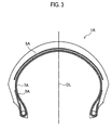
- a tire 1A of the comparative sample 1 includes a first carcass layer 5A, a second carcass layer 7A and a belt layer 9A as shown in Fig. 3 .
- the tire 1A of the comparative sample 1 does not include a supplemental layer such as the intermediate carcass layer 11.
- a tire 1B of the comparative sample 2 includes a first carcass layer 5B, a second carcass layer 7B and a belt layer 9B as shown in Fig. 4 .
- a supplemental layer 11B is provided between the first carcass layer 5B and the belt layer 9B.
- the first carcass layer and the second carcass layer are made of rayon 1840 dtex.
- the skew angles (opposite each other) of the first carcass layer and the second carcass layer to the tire circumferential direction are 75 degrees, respectively.
- the belt layer is wound spirally along the tire circumferential direction.
- a skew angle of the belt layer to the tire circumferential direction is zero degree.
- the intermediate carcass layer and the belt layer are made of rayon 940 dtex. Each skew angle of the intermediate carcass layer and the belt layer to the tire circumferential direction is 90 degrees.
- shear stiffness of the tire for two-wheeled motorcycles of the sample 1 is superior to that of the tire for two-wheeled motorcycles of the comparative sample 1.
- shear stiffness of the tire for two-wheeled motorcycles of the sample 1 is equivalent to that of the tire for two-wheeled motorcycles of the comparative sample 2.
- handling response i.e. driveability and stability
- handling response i.e. driveability and stability
- the tire for two-wheeled motorcycles of the sample 1 includes the intermediate carcass layer 11 between the first carcass layer 5 and the second carcass layer, restrained is reduction of shear stiffness against inputs in lateral and longitudinal directions and in a back-and-forth direction and thereby driveability and stability, and handling response can be improved.
Landscapes
- Engineering & Computer Science (AREA)
- Mechanical Engineering (AREA)
- Tires In General (AREA)
Abstract
Description
- The present inventions relate to a tire for two-wheeled motorcycles, especially relates to a tire for two-wheeled motorcycles including at least a first carcass layer and a second carcass layer.
- Heretofore, various proposals have been made for a pneumatic tire equipped on two-wheeled motorcycles (hereinafter, a tire for two-wheeled motorcycles). For example, a tire for two-wheeled motorcycles was disclosed, in which a belt layer is provided outside a carcass layer and a supplemental belt layer is further provided to support the outside belt layer (see Patent Documents 1 to 4). In such a tire for two-wheeled motorcycles, driveability and stability can be made improved by improving tread stiffness.
- Patent Document 1: Japanese Patent Application Laid-Open NO.
S63-305007 - Patent Document 2: Japanese Patent Application Laid-Open NO.
H1-229703 - Patent Document 3: Japanese Patent Application Laid-Open NO.
H6-1105 - Patent Document 4: Japanese Patent Application Laid-Open NO.
H10-244816 - However, since the belt layer and the supplemental belt layer are layered outside the carcass layer in the above-mentioned tire for two-wheeled motorcycles, reduced is shear stiffness (so-called shear strength) against a lateral force applied from a road surface to a tread surface. Therefore, although tire stiffness (tread stiffness) can be improved, the shear stiffness against a lateral force is reduced and thereby driveability and stability, especially handling response, cannot be improved.
- Consequently, it is an object of the present inventions to provide a tire for two-wheeled motorcycles that can prevent reduction of shear stiffness and also can improve driveability and stability, especially handling response.
- A tire for two-wheeled motorcycles according to the present invention includes a first carcass layer, a second carcass layer, a belt layer and an intermediate carcass layer. The first carcass layer is folded back along circumferential surfaces of bead cores. The second carcass layer is folded back along circumferential surfaces of turnbacks of the first carcass layer. The belt layer is provided in an outer circumferential side of the first carcass layer and the second carcass layer and spirally wound along a tire circumferential direction. The intermediate carcass layer is provided between the first carcass layer and the second carcass layer and in an inner circumferential side of a tread and extends close to a tire maximum width position.
- Here, "close to a tire maximum width position" means within a ±20 mm range from the tire maximum width position.
- According to this configuration, shear stiffness against a lateral or back-and forth input can be ensured by the intermediate carcass layer provided between the first carcass layer and the second carcass layer and also in the inner circumferential side of the tread without reducing shear stiffness (so-called shear strength) against a lateral input from a road surface to a tread surface. As a result, driveability and stability, especially handling response, can be improved.
- Here, it is preferable that each skew angle of first cords composing the first carcass layer and second cords composing the second carcass layer is 70 to 85 degrees to the tire circumferential direction.
- Here, it is preferable that a skew angle of intermediate cords composing the intermediate carcass layer is almost 90 degrees to the tire circumferential direction. Here, "almost 90 degrees" includes a ±5 degrees angle range to the tire circumferential direction.
- Here, it is preferable that the number of cords per unit width of the intermediate cords is smaller than the number of cords per unit width of and second cords. If the number of cords per unit width of the intermediate cords is larger than the number of cords per unit width of the first and second cords, driveability and stability, and handling response may be reduced due to inhibition of force applying from a road surface to a tread surface.
- Here, it is preferable that thickness of the intermediate carcass layer is smaller than thickness of the first carcass layer and than thickness of the second carcass layer. If the thickness of the intermediate carcass layer is larger than the thickness of the first and second carcass layers, driveability and stability, and handling response may be reduced due to inhibition of force applying from a road surface to a tread surface.
- Here, it is preferable that the skew angle of the first cords and the skew angle of the second cords are opposite.
-
- [
Fig. 1] Fig. 1 is a cross sectional diagram along a tread width direction showing a tire for two-wheeled motorcycles according to a present embodiment. - [
Fig. 2] Fig. 2 is a plan view diagram showing carcass layers, a carcass intermediate layer and a belt layer that configure the tire for two-wheeled motorcycles according to the present embodiment. - [
Fig. 3] Fig. 3 is a cross sectional diagram along a tread width direction showing a tire for two-wheeled motorcycles according to a comparative sample 1. - [
Fig. 4] Fig. 4 is a cross sectional diagram along a tread width direction showing a tire for two-wheeled motorcycles according to a comparative sample 2. - One embodiment of a tire for two-wheeled motorcycles according to the present invention will be explained with reference to diagrams. Note that, in respect to descriptions on the drawings, each equivalent or corresponding configuration is allocated to an equivalent or corresponding numeral. However, the drawings are shown in outline, and thereby each actual proportion of dimension or the like may be different from an actual one. Therefore, each concrete dimension or the like should be determined with considering explanations below. In addition, each relation or proportion of dimension may be different between the drawings.
-
Fig. 1 is a cross sectional diagram along a tread width direction showing the tire for two-wheeled motorcycles according to the present embodiment.Fig. 2 is a plan view diagram showing carcass layers, a carcass intermediate layer and a belt layer that configure the tire for two-wheeled motorcycles according to the present embodiment. - As shown in
Fig. 1 , the tire 1 for two-wheeled motorcycles includes a pair ofbeads 3 each of which includes abead core 3a and abead filler 3b that contact with a wheel rim (not shown). - In addition, the tire 1 includes a
first carcass layer 5 that is folded back from insides toward outsides in the tread width direction along circumferential surfaces of thebead cores 3a. Further, the tire 1 includes asecond carcass layer 7 that is folded back from insides toward outsides in the tread width direction along circumferential surfaces of turnbacks of thefirst carcass layer 5. - A
belt layer 9 that is spirally wound along a tire circumferential direction is provided in the outer circumferential side of thefirst carcass layer 5 and thesecond carcass layer 7. In addition, atread 13 that contacts with a road surface is provided in the outer circumferential side of thebelt layer 9. - An
intermediate carcass layer 11 that extends close to a tire maximum width position is provided between thefirst carcass layer 5 and thesecond carcass layer 7. Note that theintermediate carcass layer 11 is positioned in an inner circumferential side of thetread 13. Specifically, each edge of theintermediate carcass layer 11 is within a ±20 mm range from tire maximum width points FW (so-called a case line). Theintermediate carcass layer 11 reinforces stiffness of thefirst carcass layer 5 and thesecond carcass layer 7. In addition, the thickness (Ta) of theintermediate carcass layer 11 is smaller than the thickness (T1) of thefirst carcass layer 5 or the thickness (T2) of thesecond carcass layer 7. - Here, as shown in
Fig. 2 , 70 to 85 degrees is a skew angle (α) offirst cords 5a composing thefirst carcass layer 5 andsecond cords 7a of thesecond carcass layer 7 to the tire circumferential direction. Thefirst cords 5a are counter-skewed to the second cords in order to ensure stiffness of the tire 1 (stiffness of the tread 13). - Note that, if the skew angle (α) to the tire circumferential direction is smaller than 70 degrees, lateral stiffness against a lateral input (a lateral direction on paper in
Fig. 2 ) from a road surface to a tread surface may become too high. On the other hand, if the skew angle (α) to the tire circumferential direction is larger than 85 degrees, shear stiffness against a back-and-forth input (a longitudinal direction on paper inFig. 2 ) from a road surface to a tread surface may not be able to be improved. - In addition, almost 90 degrees is a skew angle (β) of
intermediate cords 11a composing theintermediate carcass layer 11 to the tire circumferential direction. Further, the number of cords per unit width of theintermediate cords 11a is smaller than that of thefirst cords 5a and than that of thesecond cords 7a. - According to the above-mentioned tire 1 of the present embodiment, since the
intermediate carcass layer 11 is provided between thefirst carcass layer 5 and the second carcass layer 7 (and also in the inner circumferential side of the tread 13), shear stiffness against a lateral or back-and forth input can be improved without reducing shear stiffness (so-called shear strength) against a lateral input from a road surface to a tread surface. Therefore, driveability and stability, especially handling response, can be improved. - In heavy-weighted two-wheeled motorcycles, it is needed that appropriate shear stiffness against an applied load is ensured at a longitudinal or back-and-forth input. Therefore, driveability and stability, and handling response can be improved by improving shear stiffness against longitudinal and back-and-forth inputs with the
intermediate carcass layer 11. - Especially, shear stiffness against longitudinal and back-and-forth inputs can be further improved by setting the skew angle (α) of the
first cords 5a and thesecond cords 7a to the tire circumferential direction within 70 to 85 degrees and also setting the skew angle (β) ofintermediate cords 11a to the tire circumferential direction to almost 90 degrees. As a result, driveability and stability, and handling response can be further improved. - In addition, inhibition of force applying from a road surface to a tread surface is prevented by making thickness (Ta) of the
intermediate carcass layer 11 smaller than thickness (T1) of thefirst carcass layer 5 and than thickness (T2) of thesecond carcass layer 7 and also making the number of cords per unit width of theintermediate cords 11a smaller than that of thefirst cords 5a and than that of thesecond cords 7a, and thereby driveability and stability, and handling response can be improved. - As described above, although contents of the present invention have been disclosed through the embodiments of the present invention, it should not be considered that descriptions and the drawings composing a portion of the disclosure limits the present invention.
- Specifically, the above-described tire 1 includes a
single belt layer 9. However, the tire according to the present invention is not limited to this configuration and may include plural belt layers. - In addition, the
first carcass layer 5 and thesecond carcass layer 7 are folded back from insides toward outsides in the tread width direction along the circumferential surfaces of thebead cores 3a, respectively, in the above-explained tire 1. However, they are not limited to this configuration and the first carcass layer and the second carcass layer can be folded back from outsides toward insides in the tread width direction along the circumferential surfaces of the bead cores, respectively. - Note that it has been explained in the above description that the
second carcass layer 7, theintermediate carcass layer 11 and thefirst carcass layer 5 are provided in order from the tire inner circumferential side to the outer circumferential side. However, it can be expressed that the first carcass layer, the intermediate carcass layer and the second carcass layer are provided in order from the tire inner circumferential side to the outer circumferential side. - Based on the disclosure, various alternative embodiments, modes of the invention and operable technologies may be obvious to the person having ordinary skill in the art. Therefore, a technical scope of the present invention is defined only by a subject matter sought to be patented in claims appropriately derived from the above explanation.
- Test results with tires for two-wheeled motorcycles of a sample 1 to which the present invention was applied and comparative samples 1 and 2 will be explained in order to clarify advantages of the present invention. The present invention does not suffer any limitations by these samples. Note that each size of the tires for two-wheeled motorcycles was 120/70ZR17M/C.
- Here, the tire 1 of the sample 1 is the above described one shown in
Fig. 1 . In addition, atire 1A of the comparative sample 1 includes afirst carcass layer 5A, asecond carcass layer 7A and abelt layer 9A as shown inFig. 3 . Thetire 1A of the comparative sample 1 does not include a supplemental layer such as theintermediate carcass layer 11. - A
tire 1B of the comparative sample 2 includes afirst carcass layer 5B, asecond carcass layer 7B and abelt layer 9B as shown inFig. 4 . In thetire 1B of the comparative sample 2, asupplemental layer 11B is provided between thefirst carcass layer 5B and thebelt layer 9B. - Note that, in each of the tires for two-wheeled motorcycles, the first carcass layer and the second carcass layer are made of rayon 1840 dtex. The skew angles (opposite each other) of the first carcass layer and the second carcass layer to the tire circumferential direction are 75 degrees, respectively. In addition, the belt layer is wound spirally along the tire circumferential direction. A skew angle of the belt layer to the tire circumferential direction is zero degree. Furthermore, the intermediate carcass layer and the belt layer are made of rayon 940 dtex. Each skew angle of the intermediate carcass layer and the belt layer to the tire circumferential direction is 90 degrees.
- Shear stiffness (in lateral and longitudinal directions and a back-and-forth direction) and handling response of these tires for two-wheeled vehicles will be explained with reference to Table 1.
-

- Defined as "100" is shear stiffness against an input in a lateral or longitudinal direction or a back-and-forth direction in respect to the tire for two-wheeled motorcycles of the sample 1, the tires for two-wheeled motorcycles of the comparative samples 1 and 2 was relatively evaluated. The larger value is indicated, the better shear stiffness is.
- Consequently, shear stiffness of the tire for two-wheeled motorcycles of the sample 1 is superior to that of the tire for two-wheeled motorcycles of the comparative sample 1. In addition, shear stiffness of the tire for two-wheeled motorcycles of the sample 1 is equivalent to that of the tire for two-wheeled motorcycles of the comparative sample 2.
- Defined as "100" is a handling response in respect to a two-wheeled motorcycle (1800 cc) equipped with the tire of the sample 1, a sensory evaluation for handling response was conducted by a professional driver on a test course with respect to each two-wheeled motorcycle equipped with the tires of the comparative samples 1 and 2. The larger value is indicated, the better handling response is.
- Consequently, handling response (i.e. driveability and stability) of the two-wheeled motorcycle equipped with the tire of the sample 1 is superior to those of the two-wheeled motorcycles equipped with the tires of the comparative samples 1 and 2.
- In this manner, since the tire for two-wheeled motorcycles of the sample 1 includes the
intermediate carcass layer 11 between thefirst carcass layer 5 and the second carcass layer, restrained is reduction of shear stiffness against inputs in lateral and longitudinal directions and in a back-and-forth direction and thereby driveability and stability, and handling response can be improved. - According to the tire for two-wheeled motorcycles of the present invention, reduction of shear stiffness is restrained by providing the intermediate carcass layer between the first and second carcass layers and in the inner circumferential side of the belt layer and thereby driveability and stability, especially handling response, can be improved.
Claims (6)
- A tire for two-wheeled motorcycles, comprising:a first carcass layer folded back along circumferential surfaces of bead cores;a second carcass layer folded back along circumferential surfaces of turnbacks of the first carcass layer;a belt layer provided in an outer circumferential side of the first carcass layer and the second carcass layer and spirally wound along a tire circumferential direction; andan intermediate carcass layer provided between the first carcass layer and the second carcass layer and in an inner circumferential side of a tread and extending close to a tire maximum width position.
- The tire for two-wheeled motorcycles according to claim 1, wherein
each skew angle of first cords composing the first carcass layer and second cords composing the second carcass layer is 70 to 85 degrees to the tire circumferential direction. - The tire for two-wheeled motorcycles according to claim 1 or 2, wherein
a skew angle of intermediate cords composing the intermediate carcass layer is almost 90 degrees to the tire circumferential direction. - The tire for two-wheeled motorcycles according to any one of claims 1 to 3, wherein
the number of cords per unit width of the intermediate cords is smaller than the number of cords per unit width of the first cords and than the number of cords per unit width of the second cords. - The tire for two-wheeled motorcycles according to any one of claims 1 to 4, wherein
thickness of the intermediate carcass layer is smaller than thickness of the first carcass layer and than thickness of the second carcass layer. - The tire for two-wheeled motorcycles according to any one of claims 1 to 5, wherein
the skew angle of the first cords and the skew angle of the second cords are opposite.
Applications Claiming Priority (2)
| Application Number | Priority Date | Filing Date | Title |
|---|---|---|---|
| JP2006034389A JP2007210535A (en) | 2006-02-10 | 2006-02-10 | Tire for motorcycle |
| PCT/JP2007/051559 WO2007091460A1 (en) | 2006-02-10 | 2007-01-31 | Tire for two-wheeled motor vehicle |
Publications (3)
| Publication Number | Publication Date |
|---|---|
| EP1982847A1 true EP1982847A1 (en) | 2008-10-22 |
| EP1982847A4 EP1982847A4 (en) | 2010-04-28 |
| EP1982847B1 EP1982847B1 (en) | 2011-09-21 |
Family
ID=38345063
Family Applications (1)
| Application Number | Title | Priority Date | Filing Date |
|---|---|---|---|
| EP07713730A Not-in-force EP1982847B1 (en) | 2006-02-10 | 2007-01-31 | Tire for two-wheeled motor vehicle |
Country Status (5)
| Country | Link |
|---|---|
| US (1) | US8191595B2 (en) |
| EP (1) | EP1982847B1 (en) |
| JP (1) | JP2007210535A (en) |
| ES (1) | ES2371284T3 (en) |
| WO (1) | WO2007091460A1 (en) |
Cited By (1)
| Publication number | Priority date | Publication date | Assignee | Title |
|---|---|---|---|---|
| EP4296087A4 (en) * | 2021-06-04 | 2024-08-14 | Sumitomo Rubber Industries Ltd. | MOTORCYCLE TIRE |
Families Citing this family (3)
| Publication number | Priority date | Publication date | Assignee | Title |
|---|---|---|---|---|
| JP5201961B2 (en) * | 2007-11-26 | 2013-06-05 | 株式会社ブリヂストン | Pneumatic tires for motorcycles |
| JP7251204B2 (en) * | 2019-02-20 | 2023-04-04 | 住友ゴム工業株式会社 | motorcycle tires |
| JP7740051B2 (en) * | 2021-06-04 | 2025-09-17 | 住友ゴム工業株式会社 | Motorcycle tires |
Family Cites Families (14)
| Publication number | Priority date | Publication date | Assignee | Title |
|---|---|---|---|---|
| US2939503A (en) * | 1956-01-16 | 1960-06-07 | Cleveland Trust Co | Building ply for pneumatic tires |
| US3730246A (en) * | 1968-03-15 | 1973-05-01 | Goodrich Co B F | Pneumatic tire |
| JPS63170103A (en) * | 1986-12-30 | 1988-07-14 | Yokohama Rubber Co Ltd:The | Large size pneumatic bias tire |
| JPS63305007A (en) | 1987-06-05 | 1988-12-13 | Sumitomo Rubber Ind Ltd | Tire for automatic motorcycle |
| JPH01229703A (en) | 1988-03-11 | 1989-09-13 | Yokohama Rubber Co Ltd:The | Pneumatic bias tire |
| JPH061105A (en) | 1992-06-19 | 1994-01-11 | Bridgestone Corp | Bias tire for aircraft |
| JPH08216619A (en) * | 1995-02-13 | 1996-08-27 | Bridgestone Corp | Pneumatic tire used for motorcycle |
| JPH10244816A (en) | 1997-03-04 | 1998-09-14 | Yokohama Rubber Co Ltd:The | Pneumatic radial tire |
| JP4242959B2 (en) * | 1998-12-15 | 2009-03-25 | 株式会社ブリヂストン | Pneumatic tires for motorcycles |
| JP4307787B2 (en) * | 2002-05-02 | 2009-08-05 | 住友ゴム工業株式会社 | Motorcycle tire and manufacturing method thereof |
| EP1615782A1 (en) * | 2003-03-26 | 2006-01-18 | Pirelli Pneumatici Societa' Per Azioni | Pneumatic tyre for two wheeled vehicles |
| JP4156450B2 (en) * | 2003-06-16 | 2008-09-24 | 住友ゴム工業株式会社 | Motorcycle tires |
| JP2005254993A (en) * | 2004-03-11 | 2005-09-22 | Bridgestone Corp | Pneumatic radial tire |
| JP4498778B2 (en) | 2004-03-12 | 2010-07-07 | 株式会社ブリヂストン | Pneumatic tire |
-
2006
- 2006-02-10 JP JP2006034389A patent/JP2007210535A/en active Pending
-
2007
- 2007-01-31 EP EP07713730A patent/EP1982847B1/en not_active Not-in-force
- 2007-01-31 ES ES07713730T patent/ES2371284T3/en active Active
- 2007-01-31 US US12/278,923 patent/US8191595B2/en not_active Expired - Fee Related
- 2007-01-31 WO PCT/JP2007/051559 patent/WO2007091460A1/en not_active Ceased
Cited By (1)
| Publication number | Priority date | Publication date | Assignee | Title |
|---|---|---|---|---|
| EP4296087A4 (en) * | 2021-06-04 | 2024-08-14 | Sumitomo Rubber Industries Ltd. | MOTORCYCLE TIRE |
Also Published As
| Publication number | Publication date |
|---|---|
| EP1982847A4 (en) | 2010-04-28 |
| EP1982847B1 (en) | 2011-09-21 |
| US8191595B2 (en) | 2012-06-05 |
| JP2007210535A (en) | 2007-08-23 |
| ES2371284T3 (en) | 2011-12-29 |
| WO2007091460A1 (en) | 2007-08-16 |
| US20100163149A1 (en) | 2010-07-01 |
Similar Documents
| Publication | Publication Date | Title |
|---|---|---|
| JP5030978B2 (en) | Pneumatic tire | |
| EP2050585A1 (en) | Floating two-ply tire | |
| EP3587144B1 (en) | Pneumatic tire | |
| CN104968510B (en) | Tyre for heavy load | |
| EP2543522B1 (en) | Two-wheeled automotive vehicle tire | |
| EP1982847B1 (en) | Tire for two-wheeled motor vehicle | |
| CN101605665A (en) | Air-inflation tyre | |
| JP2008265499A (en) | Pneumatic tire | |
| JP4568681B2 (en) | Pneumatic tire | |
| JP2008296865A (en) | Pneumatic tire | |
| JP4231085B1 (en) | Pneumatic tires for motorcycles | |
| CN105473346B (en) | Tire for motorcycle | |
| JP5081465B2 (en) | Pneumatic tire | |
| CN114555386A (en) | Run-flat tire | |
| JPH1111112A (en) | Pneumatic raidal tire | |
| JP5742122B2 (en) | Pneumatic tire | |
| JP2010167903A (en) | Tire | |
| JP2003237322A (en) | Pneumatic tire | |
| JP5038766B2 (en) | Pneumatic tire | |
| JP2006188147A (en) | Pneumatic tire | |
| WO2021100302A1 (en) | Pneumatic tire | |
| JP2002331807A (en) | Pneumatic radial tire | |
| JP2008279877A (en) | Pneumatic radial tire | |
| JP6503257B2 (en) | Motorcycle tire | |
| JP5504003B2 (en) | tire |
Legal Events
| Date | Code | Title | Description |
|---|---|---|---|
| PUAI | Public reference made under article 153(3) epc to a published international application that has entered the european phase |
Free format text: ORIGINAL CODE: 0009012 |
|
| 17P | Request for examination filed |
Effective date: 20080815 |
|
| AK | Designated contracting states |
Kind code of ref document: A1 Designated state(s): DE ES FR GB IT |
|
| DAX | Request for extension of the european patent (deleted) | ||
| RBV | Designated contracting states (corrected) |
Designated state(s): DE ES FR GB IT |
|
| A4 | Supplementary search report drawn up and despatched |
Effective date: 20100325 |
|
| 17Q | First examination report despatched |
Effective date: 20100719 |
|
| RIC1 | Information provided on ipc code assigned before grant |
Ipc: B60C 9/08 20060101AFI20101222BHEP Ipc: B60C 9/18 20060101ALI20101222BHEP |
|
| GRAP | Despatch of communication of intention to grant a patent |
Free format text: ORIGINAL CODE: EPIDOSNIGR1 |
|
| GRAS | Grant fee paid |
Free format text: ORIGINAL CODE: EPIDOSNIGR3 |
|
| GRAA | (expected) grant |
Free format text: ORIGINAL CODE: 0009210 |
|
| RIN1 | Information on inventor provided before grant (corrected) |
Inventor name: OSHIMA, MASATOMOC/O BRIDGESTONE CORPORATIONAL TECH |
|
| AK | Designated contracting states |
Kind code of ref document: B1 Designated state(s): DE ES FR GB IT |
|
| REG | Reference to a national code |
Ref country code: GB Ref legal event code: FG4D |
|
| REG | Reference to a national code |
Ref country code: DE Ref legal event code: R096 Ref document number: 602007017350 Country of ref document: DE Effective date: 20111201 |
|
| REG | Reference to a national code |
Ref country code: ES Ref legal event code: FG2A Ref document number: 2371284 Country of ref document: ES Kind code of ref document: T3 Effective date: 20111229 |
|
| PLBE | No opposition filed within time limit |
Free format text: ORIGINAL CODE: 0009261 |
|
| STAA | Information on the status of an ep patent application or granted ep patent |
Free format text: STATUS: NO OPPOSITION FILED WITHIN TIME LIMIT |
|
| 26N | No opposition filed |
Effective date: 20120622 |
|
| REG | Reference to a national code |
Ref country code: DE Ref legal event code: R097 Ref document number: 602007017350 Country of ref document: DE Effective date: 20120622 |
|
| REG | Reference to a national code |
Ref country code: FR Ref legal event code: CA Effective date: 20140812 |
|
| REG | Reference to a national code |
Ref country code: FR Ref legal event code: PLFP Year of fee payment: 10 |
|
| PGFP | Annual fee paid to national office [announced via postgrant information from national office to epo] |
Ref country code: IT Payment date: 20160127 Year of fee payment: 10 Ref country code: ES Payment date: 20160112 Year of fee payment: 10 |
|
| PGFP | Annual fee paid to national office [announced via postgrant information from national office to epo] |
Ref country code: GB Payment date: 20160120 Year of fee payment: 10 |
|
| REG | Reference to a national code |
Ref country code: FR Ref legal event code: PLFP Year of fee payment: 11 |
|
| GBPC | Gb: european patent ceased through non-payment of renewal fee |
Effective date: 20170131 |
|
| PG25 | Lapsed in a contracting state [announced via postgrant information from national office to epo] |
Ref country code: GB Free format text: LAPSE BECAUSE OF NON-PAYMENT OF DUE FEES Effective date: 20170131 |
|
| REG | Reference to a national code |
Ref country code: FR Ref legal event code: PLFP Year of fee payment: 12 |
|
| PG25 | Lapsed in a contracting state [announced via postgrant information from national office to epo] |
Ref country code: IT Free format text: LAPSE BECAUSE OF NON-PAYMENT OF DUE FEES Effective date: 20170131 |
|
| PG25 | Lapsed in a contracting state [announced via postgrant information from national office to epo] |
Ref country code: ES Free format text: LAPSE BECAUSE OF NON-PAYMENT OF DUE FEES Effective date: 20170131 |
|
| REG | Reference to a national code |
Ref country code: ES Ref legal event code: FD2A Effective date: 20181116 |
|
| PG25 | Lapsed in a contracting state [announced via postgrant information from national office to epo] |
Ref country code: ES Free format text: LAPSE BECAUSE OF NON-PAYMENT OF DUE FEES Effective date: 20170201 |
|
| PGFP | Annual fee paid to national office [announced via postgrant information from national office to epo] |
Ref country code: DE Payment date: 20190123 Year of fee payment: 13 Ref country code: FR Payment date: 20190124 Year of fee payment: 13 |
|
| REG | Reference to a national code |
Ref country code: DE Ref legal event code: R119 Ref document number: 602007017350 Country of ref document: DE |
|
| PG25 | Lapsed in a contracting state [announced via postgrant information from national office to epo] |
Ref country code: FR Free format text: LAPSE BECAUSE OF NON-PAYMENT OF DUE FEES Effective date: 20200131 Ref country code: DE Free format text: LAPSE BECAUSE OF NON-PAYMENT OF DUE FEES Effective date: 20200801 |