EP1982645A1 - Method and apparatus for displaying a field of a brain of a patient and navigation system for brain surgery - Google Patents
Method and apparatus for displaying a field of a brain of a patient and navigation system for brain surgery Download PDFInfo
- Publication number
- EP1982645A1 EP1982645A1 EP08007595A EP08007595A EP1982645A1 EP 1982645 A1 EP1982645 A1 EP 1982645A1 EP 08007595 A EP08007595 A EP 08007595A EP 08007595 A EP08007595 A EP 08007595A EP 1982645 A1 EP1982645 A1 EP 1982645A1
- Authority
- EP
- European Patent Office
- Prior art keywords
- brain
- images
- field
- patient
- image
- Prior art date
- Legal status (The legal status is an assumption and is not a legal conclusion. Google has not performed a legal analysis and makes no representation as to the accuracy of the status listed.)
- Withdrawn
Links
- 210000004556 brain Anatomy 0.000 title claims abstract description 117
- 238000000034 method Methods 0.000 title claims abstract description 65
- 238000001356 surgical procedure Methods 0.000 title claims description 10
- 230000010412 perfusion Effects 0.000 claims abstract description 11
- 238000004458 analytical method Methods 0.000 claims description 61
- 230000002123 temporal effect Effects 0.000 claims description 36
- 210000000601 blood cell Anatomy 0.000 claims description 16
- 230000004936 stimulating effect Effects 0.000 claims description 12
- 239000002245 particle Substances 0.000 claims description 8
- 230000005540 biological transmission Effects 0.000 claims description 6
- 230000010354 integration Effects 0.000 claims description 4
- 230000008569 process Effects 0.000 claims description 3
- 238000000295 emission spectrum Methods 0.000 claims description 2
- 230000035935 pregnancy Effects 0.000 claims description 2
- 230000008786 sensory perception of smell Effects 0.000 claims description 2
- 230000015541 sensory perception of touch Effects 0.000 claims description 2
- 238000011144 upstream manufacturing Methods 0.000 claims description 2
- 230000000007 visual effect Effects 0.000 claims description 2
- 230000000638 stimulation Effects 0.000 abstract description 17
- 210000004369 blood Anatomy 0.000 abstract description 15
- 239000008280 blood Substances 0.000 abstract description 15
- 230000033001 locomotion Effects 0.000 abstract description 13
- 210000003128 head Anatomy 0.000 description 16
- 230000017531 blood circulation Effects 0.000 description 11
- 210000004204 blood vessel Anatomy 0.000 description 10
- 238000001228 spectrum Methods 0.000 description 10
- 230000035515 penetration Effects 0.000 description 8
- 238000011156 evaluation Methods 0.000 description 7
- 238000010586 diagram Methods 0.000 description 6
- 230000008859 change Effects 0.000 description 5
- 230000007423 decrease Effects 0.000 description 5
- 238000003384 imaging method Methods 0.000 description 5
- 230000004913 activation Effects 0.000 description 4
- 210000005013 brain tissue Anatomy 0.000 description 4
- 239000003795 chemical substances by application Substances 0.000 description 4
- 230000008878 coupling Effects 0.000 description 4
- 238000010168 coupling process Methods 0.000 description 4
- 238000005859 coupling reaction Methods 0.000 description 4
- 230000001419 dependent effect Effects 0.000 description 3
- 230000000694 effects Effects 0.000 description 3
- 230000005057 finger movement Effects 0.000 description 3
- 238000005259 measurement Methods 0.000 description 3
- 238000006213 oxygenation reaction Methods 0.000 description 3
- 238000004088 simulation Methods 0.000 description 3
- 239000000126 substance Substances 0.000 description 3
- 210000001519 tissue Anatomy 0.000 description 3
- 238000003325 tomography Methods 0.000 description 3
- 241000050051 Chelone glabra Species 0.000 description 2
- 230000009471 action Effects 0.000 description 2
- 235000013361 beverage Nutrition 0.000 description 2
- 238000002591 computed tomography Methods 0.000 description 2
- 230000009849 deactivation Effects 0.000 description 2
- 238000005286 illumination Methods 0.000 description 2
- 238000001802 infusion Methods 0.000 description 2
- 238000002347 injection Methods 0.000 description 2
- 239000007924 injection Substances 0.000 description 2
- 238000007620 mathematical function Methods 0.000 description 2
- 210000001331 nose Anatomy 0.000 description 2
- 238000012545 processing Methods 0.000 description 2
- 230000003595 spectral effect Effects 0.000 description 2
- 206010028980 Neoplasm Diseases 0.000 description 1
- 229940035674 anesthetics Drugs 0.000 description 1
- 210000000709 aorta Anatomy 0.000 description 1
- 210000001367 artery Anatomy 0.000 description 1
- QVGXLLKOCUKJST-UHFFFAOYSA-N atomic oxygen Chemical compound [O] QVGXLLKOCUKJST-UHFFFAOYSA-N 0.000 description 1
- 230000008901 benefit Effects 0.000 description 1
- 238000004040 coloring Methods 0.000 description 1
- 238000010276 construction Methods 0.000 description 1
- 230000003247 decreasing effect Effects 0.000 description 1
- 238000001514 detection method Methods 0.000 description 1
- 238000000537 electroencephalography Methods 0.000 description 1
- 238000002474 experimental method Methods 0.000 description 1
- 239000003193 general anesthetic agent Substances 0.000 description 1
- 230000001678 irradiating effect Effects 0.000 description 1
- 238000002582 magnetoencephalography Methods 0.000 description 1
- 238000013507 mapping Methods 0.000 description 1
- 238000012986 modification Methods 0.000 description 1
- 230000004048 modification Effects 0.000 description 1
- 230000008555 neuronal activation Effects 0.000 description 1
- 210000001517 olfactory receptor neuron Anatomy 0.000 description 1
- 230000003287 optical effect Effects 0.000 description 1
- 229910052760 oxygen Inorganic materials 0.000 description 1
- 239000001301 oxygen Substances 0.000 description 1
- 238000010422 painting Methods 0.000 description 1
- 230000000704 physical effect Effects 0.000 description 1
- 238000002600 positron emission tomography Methods 0.000 description 1
- 230000035807 sensation Effects 0.000 description 1
- 230000035945 sensitivity Effects 0.000 description 1
- 238000007493 shaping process Methods 0.000 description 1
- 230000000392 somatic effect Effects 0.000 description 1
- 230000009466 transformation Effects 0.000 description 1
- 238000013519 translation Methods 0.000 description 1
- 230000014616 translation Effects 0.000 description 1
- 230000001960 triggered effect Effects 0.000 description 1
- 230000002792 vascular Effects 0.000 description 1
- 210000003462 vein Anatomy 0.000 description 1
- 238000011179 visual inspection Methods 0.000 description 1
Images




Classifications
-
- A—HUMAN NECESSITIES
- A61—MEDICAL OR VETERINARY SCIENCE; HYGIENE
- A61B—DIAGNOSIS; SURGERY; IDENTIFICATION
- A61B5/00—Measuring for diagnostic purposes; Identification of persons
- A61B5/0059—Measuring for diagnostic purposes; Identification of persons using light, e.g. diagnosis by transillumination, diascopy, fluorescence
-
- A—HUMAN NECESSITIES
- A61—MEDICAL OR VETERINARY SCIENCE; HYGIENE
- A61B—DIAGNOSIS; SURGERY; IDENTIFICATION
- A61B34/00—Computer-aided surgery; Manipulators or robots specially adapted for use in surgery
- A61B34/20—Surgical navigation systems; Devices for tracking or guiding surgical instruments, e.g. for frameless stereotaxis
-
- A—HUMAN NECESSITIES
- A61—MEDICAL OR VETERINARY SCIENCE; HYGIENE
- A61B—DIAGNOSIS; SURGERY; IDENTIFICATION
- A61B5/00—Measuring for diagnostic purposes; Identification of persons
- A61B5/0033—Features or image-related aspects of imaging apparatus, e.g. for MRI, optical tomography or impedance tomography apparatus; Arrangements of imaging apparatus in a room
- A61B5/004—Features or image-related aspects of imaging apparatus, e.g. for MRI, optical tomography or impedance tomography apparatus; Arrangements of imaging apparatus in a room adapted for image acquisition of a particular organ or body part
- A61B5/0042—Features or image-related aspects of imaging apparatus, e.g. for MRI, optical tomography or impedance tomography apparatus; Arrangements of imaging apparatus in a room adapted for image acquisition of a particular organ or body part for the brain
-
- A—HUMAN NECESSITIES
- A61—MEDICAL OR VETERINARY SCIENCE; HYGIENE
- A61B—DIAGNOSIS; SURGERY; IDENTIFICATION
- A61B90/00—Instruments, implements or accessories specially adapted for surgery or diagnosis and not covered by any of the groups A61B1/00 - A61B50/00, e.g. for luxation treatment or for protecting wound edges
- A61B90/10—Instruments, implements or accessories specially adapted for surgery or diagnosis and not covered by any of the groups A61B1/00 - A61B50/00, e.g. for luxation treatment or for protecting wound edges for stereotaxic surgery, e.g. frame-based stereotaxis
-
- A—HUMAN NECESSITIES
- A61—MEDICAL OR VETERINARY SCIENCE; HYGIENE
- A61B—DIAGNOSIS; SURGERY; IDENTIFICATION
- A61B90/00—Instruments, implements or accessories specially adapted for surgery or diagnosis and not covered by any of the groups A61B1/00 - A61B50/00, e.g. for luxation treatment or for protecting wound edges
- A61B90/10—Instruments, implements or accessories specially adapted for surgery or diagnosis and not covered by any of the groups A61B1/00 - A61B50/00, e.g. for luxation treatment or for protecting wound edges for stereotaxic surgery, e.g. frame-based stereotaxis
- A61B90/14—Fixators for body parts, e.g. skull clamps; Constructional details of fixators, e.g. pins
-
- A—HUMAN NECESSITIES
- A61—MEDICAL OR VETERINARY SCIENCE; HYGIENE
- A61B—DIAGNOSIS; SURGERY; IDENTIFICATION
- A61B90/00—Instruments, implements or accessories specially adapted for surgery or diagnosis and not covered by any of the groups A61B1/00 - A61B50/00, e.g. for luxation treatment or for protecting wound edges
- A61B90/36—Image-producing devices or illumination devices not otherwise provided for
-
- A—HUMAN NECESSITIES
- A61—MEDICAL OR VETERINARY SCIENCE; HYGIENE
- A61B—DIAGNOSIS; SURGERY; IDENTIFICATION
- A61B17/00—Surgical instruments, devices or methods
- A61B2017/00017—Electrical control of surgical instruments
- A61B2017/00022—Sensing or detecting at the treatment site
- A61B2017/00057—Light
- A61B2017/00061—Light spectrum
-
- A—HUMAN NECESSITIES
- A61—MEDICAL OR VETERINARY SCIENCE; HYGIENE
- A61B—DIAGNOSIS; SURGERY; IDENTIFICATION
- A61B17/00—Surgical instruments, devices or methods
- A61B2017/00017—Electrical control of surgical instruments
- A61B2017/00022—Sensing or detecting at the treatment site
- A61B2017/00057—Light
- A61B2017/00066—Light intensity
-
- A—HUMAN NECESSITIES
- A61—MEDICAL OR VETERINARY SCIENCE; HYGIENE
- A61B—DIAGNOSIS; SURGERY; IDENTIFICATION
- A61B34/00—Computer-aided surgery; Manipulators or robots specially adapted for use in surgery
- A61B34/10—Computer-aided planning, simulation or modelling of surgical operations
- A61B2034/101—Computer-aided simulation of surgical operations
- A61B2034/105—Modelling of the patient, e.g. for ligaments or bones
-
- A—HUMAN NECESSITIES
- A61—MEDICAL OR VETERINARY SCIENCE; HYGIENE
- A61B—DIAGNOSIS; SURGERY; IDENTIFICATION
- A61B34/00—Computer-aided surgery; Manipulators or robots specially adapted for use in surgery
- A61B34/10—Computer-aided planning, simulation or modelling of surgical operations
- A61B2034/107—Visualisation of planned trajectories or target regions
-
- A—HUMAN NECESSITIES
- A61—MEDICAL OR VETERINARY SCIENCE; HYGIENE
- A61B—DIAGNOSIS; SURGERY; IDENTIFICATION
- A61B34/00—Computer-aided surgery; Manipulators or robots specially adapted for use in surgery
- A61B34/20—Surgical navigation systems; Devices for tracking or guiding surgical instruments, e.g. for frameless stereotaxis
- A61B2034/2046—Tracking techniques
- A61B2034/2055—Optical tracking systems
-
- A—HUMAN NECESSITIES
- A61—MEDICAL OR VETERINARY SCIENCE; HYGIENE
- A61B—DIAGNOSIS; SURGERY; IDENTIFICATION
- A61B34/00—Computer-aided surgery; Manipulators or robots specially adapted for use in surgery
- A61B34/20—Surgical navigation systems; Devices for tracking or guiding surgical instruments, e.g. for frameless stereotaxis
- A61B2034/2046—Tracking techniques
- A61B2034/2065—Tracking using image or pattern recognition
-
- A—HUMAN NECESSITIES
- A61—MEDICAL OR VETERINARY SCIENCE; HYGIENE
- A61B—DIAGNOSIS; SURGERY; IDENTIFICATION
- A61B90/00—Instruments, implements or accessories specially adapted for surgery or diagnosis and not covered by any of the groups A61B1/00 - A61B50/00, e.g. for luxation treatment or for protecting wound edges
- A61B90/36—Image-producing devices or illumination devices not otherwise provided for
- A61B2090/364—Correlation of different images or relation of image positions in respect to the body
- A61B2090/365—Correlation of different images or relation of image positions in respect to the body augmented reality, i.e. correlating a live optical image with another image
-
- A—HUMAN NECESSITIES
- A61—MEDICAL OR VETERINARY SCIENCE; HYGIENE
- A61B—DIAGNOSIS; SURGERY; IDENTIFICATION
- A61B90/00—Instruments, implements or accessories specially adapted for surgery or diagnosis and not covered by any of the groups A61B1/00 - A61B50/00, e.g. for luxation treatment or for protecting wound edges
- A61B90/36—Image-producing devices or illumination devices not otherwise provided for
- A61B90/37—Surgical systems with images on a monitor during operation
- A61B2090/373—Surgical systems with images on a monitor during operation using light, e.g. by using optical scanners
-
- A—HUMAN NECESSITIES
- A61—MEDICAL OR VETERINARY SCIENCE; HYGIENE
- A61B—DIAGNOSIS; SURGERY; IDENTIFICATION
- A61B5/00—Measuring for diagnostic purposes; Identification of persons
- A61B5/02—Detecting, measuring or recording for evaluating the cardiovascular system, e.g. pulse, heart rate, blood pressure or blood flow
- A61B5/026—Measuring blood flow
- A61B5/0261—Measuring blood flow using optical means, e.g. infrared light
-
- A—HUMAN NECESSITIES
- A61—MEDICAL OR VETERINARY SCIENCE; HYGIENE
- A61B—DIAGNOSIS; SURGERY; IDENTIFICATION
- A61B5/00—Measuring for diagnostic purposes; Identification of persons
- A61B5/40—Detecting, measuring or recording for evaluating the nervous system
- A61B5/4058—Detecting, measuring or recording for evaluating the nervous system for evaluating the central nervous system
- A61B5/4064—Evaluating the brain
Definitions
- This invention relates to a method and an apparatus for displaying a field of a brain of a patient.
- this invention relates to a method for determining a continuous field in the brain which is activated or deactivated after a stimulation.
- the invention relates to a navigation system for brain surgery which is suitable for displaying a field of the brain and determining a continuous field of the brain.
- Image-forming methods that means methods which display extended areas of the brain are for example computer tomography (CT), magnetic resonance tomography (MRT) and ultrasonic methods.
- CT computer tomography
- MRT magnetic resonance tomography
- ultrasonic methods As methods for functionally examining the brain are known for example electro encephalography (EEG), magneto encephalography (MEG), positron emission tomography (PET) as well as functional magnetic resonance tomography (fMRT).
- EEG electro encephalography
- MEG magneto encephalography
- PET positron emission tomography
- fMRT functional magnetic resonance tomography
- a neuronal activation of certain brain areas may cause an increase of the oxidised haemoglobin in the capillaries of the activated brain tissue.
- An object of the present invention is to provide an improved method for identifying functional areas in the brain of a patient as well as to provide an apparatus for carrying out this method.
- a further object of the present invention is to provide an apparatus for brain surgeries.
- a method for displaying a field of a brain of a patient comprises: illuminating the field of the brain with measuring light and acquiring at least one first sequence of images of the illuminated field, then stimulating the patient, then illuminating the field of the brain with measuring light and acquiring at least one second sequence of images of the illuminated field, and evaluating the first and the second sequence of images by: (a) associating a first analysis image value to pixels in the first sequence of images to which pixels same locations of the field are imaged, respectively, wherein the first analysis image value depends on at least one of amplitudes and frequencies of temporal changes of the image values of these pixels, (b) associating a second analysis image value to pixels in the second sequence of images to which pixels the same locations of the field are imaged, respectively, wherein the second analysis image value depends on at least one of amplitudes and frequencies of temporal changes of image values of these pixels, and wherein the method further comprises: determining an output image from
- the skullcap of the patient is opened.
- the first sequence of images acquires a reference state of the field of the brain.
- the patient is stimulated to provoke an activation of certain areas of the brain.
- the subsequently acquired second sequence of images may represent an activated state of the field of the brain.
- An image is given by image values in a plurality of pixels.
- the image values thereby correspond to detected intensities of measuring light which has interacted with the field of the brain and is returned from there.
- Image values of pixels are analysed with respect to their temporal changes. In particular, at least one of amplitudes and frequencies of these temporal changes are used to determine for the first sequence of images a first analysis image value and to determine for the second sequence of images a second analysis image value.
- An output image is determined from first and second analysis image values and the output image is subsequently displayed.
- the displaying may be carried out in the form of a two dimensional image, a diagram, a plurality of diagrams and the like.
- the two dimensional image may be a grey scale image, a pseudo colour image, or the like.
- three dimensional illustrations may be employed.
- a dependency of the first and second analysis image value on at least one of amplitudes and frequencies of temporal changes of image values is present if the first, respectively second, analysis image value changes due to temporal changes of the first, respectively second, image values.
- a constant dependency is not meant.
- the output image is thereby determined from first and second analyses image values, so that the output image changes, if either the first or the second analysis image values change.
- the acquiring the images of the first sequence and the second sequence comprises exposing detector elements of an image detector during an exposure time of less than 1 ms, in particular less than 0.1 ms, and further in particular less than 0.03 ms. Restricting the exposure time results in accumulating the light emanating from the illuminated field of the brain only over short times of less than 1 ms to detect image values. Thus, temporal fluctuations of high frequencies can be detected which is necessary for performing the method.
- the acquiring the images of the first and the second sequence comprises acquiring temporally subsequent images having a temporal interval of less than 1 ms, in particular less than 0.1 ms, and further in particular less than 0.05 ms.
- a temporal interval of less than 1 ms, in particular less than 0.1 ms, and further in particular less than 0.05 ms.
- the acquiring the images comprises detecting measuring light, wherein intensities of the detected measuring light having wavelengths greater than 1300 nm and smaller than 600 nm, in particular greater than 820 nm and smaller than 780 nm, amount to less than 10 % of a total intensity of the detected measuring light.
- intensities of the detected measuring light having wavelengths greater than 1300 nm and smaller than 600 nm, in particular greater than 820 nm and smaller than 780 nm, amount to less than 10 % of a total intensity of the detected measuring light.
- the measuring light may exhibit a coherence length which substantially corresponds to twice the penetration depth of the measuring light into a tissue of the brain visible within the illuminated field.
- Using measuring light having this coherence length enables to detect an interference of light which was reflected by two particles which are a distance apart from each other corresponding to the penetration depth.
- it can be ensured that even the light penetrated in deepest locations of the field of the brain may interfere with light which was reflected at the surface of the field of the brain.
- a sensitivity may be increased.
- the determining the output image from the first and the second analysis image values comprises computing at least one of a difference and a ratio of first and second terms, wherein the first terms depend on the first analysis image values and the second terms depend on the second analysis image values.
- the output image may thus for example be obtained by forming a difference of first and second analysis image values multiplied with different or same factors.
- a mathematical function may be applied to the first and second analysis image values, before forming a difference is carried out. These mathematical functions comprise for example forming a logarithm, forming a power, forming a product and the like.
- a ratio thereof may be formed to obtain the output image.
- a particular simple variant to determine a difference of the field of the brain before and after the stimulating is to determine the difference between the first and second analysis image.
- a coordinate system is established relative to a head of the patient.
- the establishing a coordinate system may thereby comprise fixing a reference frame at the head of the patient.
- the head of the patient may be held at at least three pins or pillows.
- the pins or pillows thereby contact the scull of the patient.
- the coordinate system may also be established in that predetermined reference locations at the head of the patient are detected.
- the detecting predetermined reference locations may thereby comprise optically detecting.
- plural cameras may be provided to detect coordinates of at least three predetermined locations at the head of the patient. Further, the cameras are used, to determine coordinates of the apparatus for displaying a field of a brain.
- coordinates of locations of the field of the brain may be determined in the coordinate system, wherein the locations are imaged to selected pixels in the output image.
- the method further comprises determining at least one continuous region in the output image in which intensity values are greater than a threshold.
- regions in the output image which for example show large differences of analysis image values before and after the stimulation. These regions in the output image may correspond thereby to activated or deactivated areas in the field of the brain. This corresponds to identifying functional areas in the brain.
- the at least one determined region may be displayed in superposition with the output image.
- Possible illustrations thereby comprise encircling the determined region using a line, a colouring the determined region, or the like.
- coordinates of locations which are imaged to the at least one determined region in the output image are determined, in the coordinate system.
- locations of functional areas in the brain of the patient relative to a coordinate system of the head can be determined.
- At least one of the first analysis image value and the second analysis image value comprises a value representing one of a perfusion, a concentration, an average velocity, a parameter of a velocity distribution, in particular a standard deviation of the velocity distribution of particles moving relative to each other, in particular blood cells, and a combination thereof.
- the thus specified analysis image value may thereby be obtained using a frequency spectrum of the temporal changes of image values.
- the concentration of particles moving relative to each other may be obtained as a 0th moment of the frequency distribution.
- the perfusion may be obtained as a 1st moment of the frequency distribution.
- An average velocity or a parameter of the velocity distribution may be obtained as a ratio between the perfusion and the concentration of particles moving relative to each other.
- the method further comprises repeating the acquiring the at least one of the first and the second sequence of images. Further, the repeatedly acquired sequences of images are evaluated as described above. Thus, temporal sequences of first and second analysis image values are obtained. This may represent a movie of first and second analysis image values. Using such a movie a temporal course of an activation or a deactivation of brain areas after a simulation may be inferred.
- the temporal sequences of the first, respectively the second, analysis image values may be at least one of displayed and stored. Displaying the temporal sequences of the first, respectively second, analysis image values may thereby correspond to playing a movie of the first, respectively second, analysis image values.
- a storing the sequences of the first, respectively second, analysis image values may thereby also comprise a storing the coordinates of the field of the brain in the coordinate system of the head of the patient, as well as the storing a representation of the stimulation carried out between the first and second sequences.
- the stimulating comprises requesting the patient, to move a particular body part.
- This body part may for example be an extremity, such as a finger.
- the stimulating comprises applying an agent to the patient.
- the agent may be incorporated or may be externally applied.
- the applying the agent may also comprise irradiating the patient.
- the stimulating comprises applying of at least one of a visual stimulus, an acoustic stimulus, a gestation stimulus, an olfaction stimulus, and a tactition stimulus to the patient.
- images such as photographs, paintings, text, may for example be presented to the patient or sounds, such as music or speech, may be played.
- different kinds of food or beverages may be tasted by the patient, by applying the food or the beverages to the tongue of the patient, in particular by an application device. Physical properties of these applied nourishments, such as their temperature, may be controlled. Further the patient may be allowed to smell a substance by bringing the substance in proximity to its nose or introducing the substance into the patient's nose, in particular by a technical appliance. Thereby olfactory receptor neurons may be activated or deactivated.
- the patient may be allowed to experience touch or a somatic sensation.
- objects having different roughness of their surfaces, different surface shapes, or different temperatures may contact a portion of the skin of the patient or may be slid over portions of the skin of the patient applying a varying amount of pressure.
- anesthetics may be probed by applying this kind of stimulus.
- the stimulus may comprise a request to carry out a conscious action.
- This action may for example comprise moving a finger.
- the method further comprises removing a portion of the brain in dependence of at least one of the output image, the determined coordinates, and the at least one continuous region in the output image.
- the portion of the brain may comprise several regions. Thereby, a predetermined continuous region in the field of the brain may for example be circumvented to gain access to regions of the brain which are to removed. The regions to be removed may thereby be situated in layers of the brain which are located in a depth which is deeper than the penetration depth of the measuring light.
- the method further comprises acquiring an image of the field of the brain in a visible wavelength range. Further, the image in a visible wavelength region may be displayed in superposition with at least one of the first analysis image values, the second analysis image values, and the output image.
- the image in a visible wavelength region may be displayed in superposition with at least one of the first analysis image values, the second analysis image values, and the output image.
- blood vessels situated at the surface of the brain may be imaged and concurrently the determined blood flow characteristics may be displayed.
- a navigation system for brain surgery which comprises a position acquisition apparatus to acquire coordinates of locations of a brain of a patient, and a measuring apparatus for acquiring images which is configured to illuminate a field of the brain with measuring light, to acquire at least one sequence of images of the illuminated field, and to process the sequence of images by associating an analysis image value to pixels in the sequence of images to which pixels same locations of the field are imaged, respectively, wherein the analysis image value depends on at least one of amplitudes and frequencies of temporal changes of image values of these pixels.
- this system laser-Doppler-images of a field of a brain can be acquired.
- the provided position acquisition apparatus enables to associate individual points in these images to locations of the brain.
- the position acquisition apparatus may thereby be designed in different ways.
- One possibility is the provision of a head coupling system which is adapted to hold the head of the patient by at least three pins or pillows in a fixed position relative to an object plane of the measuring apparatus for acquiring images.
- the position acquisition apparatus may also be an optical position acquisition apparatus, wherein the coordinates of predetermined locations of the head of the patient are determined. Concurrently thereto the coordinates of predetermined locations of the measuring apparatus for acquiring images are determined.
- a relationship between a coordinate system of the measuring apparatus for acquiring images and a coordinate system of the brain of the patient can be determined.
- the measuring apparatus for acquiring images is adapted to temporally subsequently acquire a sequence of images of the field of the brain.
- This acquired sequence of images is then evaluated by analysing intensity values of the light emanating from the field of the brain with respect to its temporal changes, wherein the intensity values are obtained in every pixel.
- An analysis image value obtained from this analysis of the temporal changes of image values may thereby obtained using a frequency spectrum which can be determined from the temporal changes of the image values.
- moments of the frequency spectrum of the temporal changes may thereby be comprised.
- the measuring apparatus for acquiring images comprises a camera having an exposure integration time of less than 1 ms, in particular less than 0.1 ms, and further in particular less than 0.03 ms.
- the exposure integration time may be adjustable.
- a detectable frequency of a change of the temporal changes of the image values is greater than 1 kHz, in particular greater than 10 kHz, and further in particular greater than 30 kHz.
- the measuring apparatus for acquiring images comprises a camera having a frame rate greater than 1 kHz, in particular greater than 10 kHz, and further in particular greater than 20 kHz.
- a frame-rate of the camera is a frequency indicating a number of images acquired by the camera in a certain time span. If the frame-rate is for example 10 kHz the camera is enabled to acquire 10,000 images in one second. Thus it is possible, to sample the temporal changes of the image values with a frequency which is higher than 1 kHz, in particular higher as 10 kHz, and further in particular higher than 20 kHz.
- detectors of the camera comprise CMOS-sensors.
- frequency components may be determined whose frequencies are greater than 0.5 kHz, in particular greater than 5 kHz, and further in particular greater than 10 kHz.
- An analysis of the temporal changes of the image values with respect to the determining a frequency spectrum comprises thereby the determining the amplitudes and frequencies of the frequency components which, as a sum, result to the acquired temporal changes.
- a band-pass filter is arranged in a beam path upstream of the camera, wherein the transmission characteristics of the band-pass filter is adapted such that a transmission of light having wavelengths greater than 1300 nm and smaller than 600 nm, in particular greater than 820 nm and smaller than 780 nm, amounts to less than 10 % of a total transmission of the band-pass filter. This enables that only desired light emanating from the field of the brain is detected by the camera.
- the measuring apparatus comprises a light source having an emission spectrum formed such that an emitted intensity of light having wavelengths greater than 1300 nm and smaller than 600 nm, in particular greater than 820 nm and smaller than 780 nm, amounts to less than 10 % of a total intensity.
- a light source having an emission spectrum formed such that an emitted intensity of light having wavelengths greater than 1300 nm and smaller than 600 nm, in particular greater than 820 nm and smaller than 780 nm, amounts to less than 10 % of a total intensity.
- the navigation system further comprises an apparatus for acquiring images of the brain of the patient in a visible wavelength range.
- an apparatus for acquiring images of the brain of the patient in a visible wavelength range With this provision it is possible to acquire beside laser-Doppler-images also images in the visible wavelength range. This may be advantageous to associate details of the field of the brain recognizable in the visible wavelength range with details in the laser-Doppler-images. For example, a blood flow in blood vessels at the surface of the brain may thus be examined. In particular, thereby also a blood flow may be examined in areas not pervaded by blood vessels recognizable in the visible wavelength range.
- the navigation system further comprises a display apparatus for displaying an image in the visible wavelength range, in particular in superposition with analysis image values.
- a display apparatus for displaying an image in the visible wavelength range, in particular in superposition with analysis image values.
- the navigation system is adapted to perform methods of the first aspect of the present invention.
- laser-Doppler-images may be acquired before and after a stimulation and may be displayed and their changes may be determined.
- this apparatus is suited to examine a change of a blood flow characteristics in the brain triggered by a stimulation. These areas may thereby be interpreted as activated or deactivated areas.
- FIG. 1 shows an embodiment of a navigation system for brain surgeries according to an aspect of the present invention.
- the navigation system 1 comprises an imaging system 2, a measuring light camera 3, a control and evaluation unit 4, a white light camera 6, a stimulation apparatus 5 and a position acquisition apparatus 7.
- an object plane 9 of the imaging system 2 a field 11 of a brain 13 of a head 15 is arranged.
- the head 15 of the patient is connected to a base 19 using a head coupling apparatus 17 via an arrangement of levers 21. Thereby the head of the patient is held using pins 17a, 17b and a not illustrated pin 17c which are connected to the head coupling apparatus.
- a coordinate system 23 is connected to the base 19 and thus also to the head coupling apparatus 17.
- This coordinate system 23 is defined by coordinate axis x, y and z.
- the imaging system 2 is also connected via the arrangement of levers 21 to the base 19.
- the imaging system 2 comprises a light source 25 emitting light 27.
- the light source is a laser emitting light having a wavelength of 808 nm.
- the coherence length of the light amounts to some mm.
- the light 27 emanating from the light source 25 is shaped by a beam shaping optics 29 to form measuring light 31 substantially comprising plane wave fronts. Measuring light 31 traverses a semi-transparent mirror 33 and a semi-transparent mirror 35. Subsequently the measuring light is incident onto the field 11 of the brain 13.
- Measuring light having interacted at a location x, y in the field 11 of the brain 13 emanates from this location x, y, traverses the semi-transparent mirror 35 and is reflected at the semi-transparent mirror 33 to form light 37.
- Light 37 enters the measuring light camera 3. Thereby the light 37 traverses a band-pass filter 39.
- the band-pass filter allows light within a wavelength range of 780 nm to 820 nm to pass.
- the filtered light 37 traverses a camera objective 41 to be detected at a pixel (i,j) of a detector 43.
- the detector 43 comprises CMOS-sensors and is connected to the control and evaluation unit 4.
- the control and evaluation unit comprises a processing unit 45, a display unit 47, an input unit 49 and a storage unit 51.
- the processing unit 45 is adapted to evaluate a sequence of images each of which is given by image values I(i,j).
- the detailed evaluation method is described further below.
- the white light camera comprises a camera objective and a detector 44 for acquiring light in the visible wavelength range.
- a white light source not illustrated in Figure 1 illuminates the field 11 of the brain.
- White light reflected at a location (x, y) of the field of the brain is reflected at the semi-transparent mirror 35, traverses a camera objective and is detected at the pixel (i,j) of the detector 44.
- the white light image detected by the detector is displayed at the display unit 47.
- the navigation system for brain surgeries further comprises a stimulation apparatus 5 for stimulating a patient.
- the simulation apparatus comprises a stimulation controller 43 as well as a variety of apparatuses for stimulating the patient. These apparatuses comprise in this embodiment a display unit 55, a speaker 57 and an injection robot 59.
- the display unit 55 is arranged in a field of view 56 of the patient.
- the speaker 59 is within earshot of an ear 58 of the patient.
- an infusion valve 61 is connected to a blood vessel of the patient.
- a supply tube 63 is inserted into the infusion valve. Via the supply tube 63 the injection robot is enabled to apply a variety of agents into the vascular system of the patient.
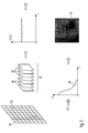
- a sequence 65 of images 66 is acquired by the detector 43 of Figure 1 .
- every image 66 comprises a quadratic field of pixels (i,j).
- the number of pixels in this embodiment is 512 x 512 pixels.
- Each pixel (i,j) of each image 66 of the sequence of images 65 is associated by the acquisition to an image value I (i,j).
- a temporal course of image values I (i,j,t) is established.
- the here illustrated method comprises an analysis of the temporal changes of these image values.
- the image values are composed of a constant part not changing over time and a fluctuation part representing a change of the image values over time.
- a frequency spectrum of the temporal course of the image values is computed.
- the frequency spectrum may for example be obtained by a Fourier transformation.
- the FFT fast Fourier transform
- the frequency spectrum S(v) of the temporal changes of the image values is depicted and indicated by reference number 68.
- the frequency f is depicted and on the Y-axis the amplitude A of the respective frequency component is depicted.
- the frequency spectrum S(v) is commonly also referred to as power spectrum. It represents the amplitudes and frequencies of the temporally changing image values I (i,j,t).
- a first moment of the power spectrum is computed to compute for every pixel of the sequence 65 of images an analysis image value. This first moment is also referred to as a perfusion.
- a concentration C, or a velocity V of particles moving relative to each other may be computed as analysis image value according to the following formulas:
- V M 1 M 0
- S v ⁇ 0 ⁇ I t ⁇ exp - i ⁇ 2 ⁇ ⁇ vt ⁇ dt 2 .
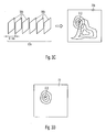
- Figure 3 shows an embodiment of a method according to the invention.
- a field of a brain of a patient is arranged in the object plane 9 of the imaging system 2 of the navigation system 1 for brain surgeries.
- the scull of the patient is opened to allow measuring light 31 to be incident onto a field 11 of the brain of the patient.
- first a first sequence 65a of images 66a is acquired.
- the images 66a are acquired having a temporal interval of less than 0.1 ms.
- the acquired first sequence 65a of images 66a is then evaluated according to the evaluation method with reference to Figure 2 .
- a first analysis image 70a is obtained representing information about a blood flow within the field 11 of the brain 13.
- the patient is then stimulated.
- the stimulating comprises a request to lift a finger 64.
- the patient follows the request and lifts the finger 64.
- a second sequence 65b of images 66b of the field of the brain of the patient is acquired. Again, a temporal interval between acquisitions of subsequent images 66b is smaller than 0.1 ms.
- the second sequence of images 66b is evaluated to obtain a second analysis image 70b.
- an output image 72 is computed from a computation involving the first and the second analysis image, as illustrated in Figure 3D .
- the computing comprises forming a difference between the first and the second analysis image.
- the analysis image 72 is illustrated using contour lines in Figure 3D . It is apparent that in a region around the pixel (i,j) the output image 72 exhibits increased values. These increased values around the pixel (i,j) may indicate that areas around the corresponding location (x,y) of the field of the brain of the patient have been activated or deactivated by the stimulating illustrated in Figure 3B .
- FIG. 4 illustrates principles of the measurement according to an embodiment of the present invention.
- Light 31 is incident onto a field 11 of a brain of a patient.
- the light has a wavelength of 808 nm and is generated by a laser.
- a penetration depth of light of this wavelength into brain tissue amounts to about 1 mm to 2 mm.
- the spectral width of the light 31 having wavelength 880 nm generated by the laser is chosen such that a coherence length of the light results which lies in the range of the penetration depth of the light.
- the penetration depth may amount to more or less than 1 mm to 2 mm.
- the incident light 31 is incident onto blood cells 73 and blood cells 75.
- Blood cells 73 are substantially at rest with respect to the examined field 11 of the brain.
- blood cells 75 (illustrated as circles having a striped filling) move relative to the examined field 11 of the brain according to a certain velocity whose magnitude and direction is indicated by arrows originating at the respective blood cell in Figure 4 .
- the light 31 is reflected at the blood cells 73 and 75 and is scattered. While blood cells 73 being at rest relative to the field 11 reflect light 31 as light having the same wavelength ⁇ 0 as the one of the incident light 31, blood cells 75 moving relative to the field 11 reflect the incident light 31 with wavelengths ⁇ 0 + ⁇ different from the wavelengths of the incident light.
- blood cells 75 move in a direction of the incident light 31, they reflect light with a wavelength which is greater than the wavelength of the incident light 31. If blood cells 75 move in a direction opposite to the incoming light 31, they reflect the light with wavelengths which are smaller than the wavelengths of the incident light. A plurality of blood cells 73 und 75 are hit by the incident light 31.
- the light reflected from this plurality of blood cells comprises, dependent on the velocity of the plurality of blood cells, wavelengths which are greater and smaller than the wavelength of the incident light. This velocity dependent shift of the wavelengths of the light is commonly referred to as Doppler-Effect. Light having different wavelengths and different relative phases superimposes, to be detected at a pixel of the detector 43.
- a superposition of light having slightly different wavelengths results in a temporally fluctuating signal which may also be denoted as beat signal.
- beat signal the different wavelengths generating this beat signals can be inferred.
- the different velocities of the blood cells may be inferred which have generated the detected light by reflection.
- a further great advantage of this method is a high time resolution which lies in the range of below one second.
- changes of a blood motion due to external influences or stimulations may be examined.
- identify functional areas in the brain of a human Identified areas in the brain may also be accounted for during brain surgeries.
- functional areas may be circumvented to gain access to a region of the brain to be removed which region lies in deeper layers of the brain.
- the area to be removed may in particular be a tumour in the brain of the patient.
- Figure 5A shows a white light image 74 of a field of a brain of a patient, wherein the patient's skullcap is opened. On the surface of the brain of the patient several blood vessels 76 are visible. These blood vessels comprise arteries and veins. The blood vessels branch out more and more to continue into micro capillaries 78. Between the blood vessels white brain tissue is visible.
- Figure 5B shows a laser-Doppler-image 70 acquired from the same field of the brain of the patient. Higher values of a blood flow, respectively perfusion, are depicted by brighter grey values.
- areas of the field of the brain which show blood vessels in the white light image indicate in the laser-Doppler-image a rather decreased blood motion.
- a possible explanation may be that a blood motion in the blood vessels apparent in the white light image 74 is too fast that it may not anymore be acquired using the embodiment of the measuring apparatus illustrated here. Indeed blood flow velocities in aortas amount to up to some meters per second.
- Blood flow velocities decrease in middle sized and smaller capillaries to some centimetres per second. Only in very small micro capillaries blood flow velocities of some millimetres per second are found which may be detected by the measuring apparatus of the present embodiment.
- the white light image 74 and the laser-Doppler-image 70 are obtained by simultaneous illumination with laser light and white light and simultaneous detection.
- Figure 6 shows a diagram depicting an average of analysis image values of all pixels of a laser-Doppler-image in dependence of time t in units of seconds s.
- the diagram in Figure 6 represents an average blood motion in a field of a brain of a human over time.
- the patient was requested at the time points 82 to count loudly.
- the patient was requested to stop counting.
- This sequence of requests was repeatedly performed, wherein the requests for counting and for stopping the counting were performed for different time spans.
- Figures 7A and 7B show output images according to the method for displaying a field of a brain superimposed with white light images of the same field of the brain.
- the numbers along the image edges indicate pixel indices.
- the white light image thereby is illustrated as grey scale image in Figures 7A and 7B , respectively.
- the output image is illustrated as contour line image.
- the output image was obtained in the following way: First and second sequences of images were acquired, wherein the patient moved a finger during the acquisition of the second sequence of images. Thereby eight sequences of images were acquired, where upon the patient moved the finger and alternating thereto eight sequences of images were acquired, where upon the patient kept the finger calmly.
- the output images depicted in Figure 7A and 7B were obtained by comparison of the average value of the images of the first sequences with the average value of the images of the second sequences. While contour lines in the image of Figure 7A indicate an increase of a perfusion or a blood motion in the field of the brain, contour lines in the image of Figure 7B indicate a decrease of the perfusion or the blood motion of the field of the brain due to the moving a finger. It is apparent that in a central lower area of the acquired field of the brain a pronounced decrease of the blood motion was detected during the moving the finger.
Landscapes
- Health & Medical Sciences (AREA)
- Life Sciences & Earth Sciences (AREA)
- Surgery (AREA)
- Engineering & Computer Science (AREA)
- General Health & Medical Sciences (AREA)
- Public Health (AREA)
- Animal Behavior & Ethology (AREA)
- Veterinary Medicine (AREA)
- Biomedical Technology (AREA)
- Heart & Thoracic Surgery (AREA)
- Medical Informatics (AREA)
- Molecular Biology (AREA)
- Nuclear Medicine, Radiotherapy & Molecular Imaging (AREA)
- Pathology (AREA)
- Oral & Maxillofacial Surgery (AREA)
- Biophysics (AREA)
- Physics & Mathematics (AREA)
- Radiology & Medical Imaging (AREA)
- Neurology (AREA)
- Neurosurgery (AREA)
- Robotics (AREA)
- Measurement Of The Respiration, Hearing Ability, Form, And Blood Characteristics Of Living Organisms (AREA)
- Magnetic Resonance Imaging Apparatus (AREA)
- Investigating Or Analysing Materials By Optical Means (AREA)
- Measuring And Recording Apparatus For Diagnosis (AREA)
- Measuring Pulse, Heart Rate, Blood Pressure Or Blood Flow (AREA)
- Length Measuring Devices By Optical Means (AREA)
Abstract
Description
- This invention relates to a method and an apparatus for displaying a field of a brain of a patient. In particular, this invention relates to a method for determining a continuous field in the brain which is activated or deactivated after a stimulation. Further, the invention relates to a navigation system for brain surgery which is suitable for displaying a field of the brain and determining a continuous field of the brain.
- From the prior art a variety of methods for examining the brain are known. Image-forming methods, that means methods which display extended areas of the brain are for example computer tomography (CT), magnetic resonance tomography (MRT) and ultrasonic methods. As methods for functionally examining the brain are known for example electro encephalography (EEG), magneto encephalography (MEG), positron emission tomography (PET) as well as functional magnetic resonance tomography (fMRT). In recent years in particular the functional magnetic resonance tomography (fMRT) contributed to a large extend to the understanding of the construction of the brain. A neuronal activation of certain brain areas may cause an increase of the oxidised haemoglobin in the capillaries of the activated brain tissue. Using fMRT it is possible to locally detect the increase of the oxidised haemoglobin. A contrast due to a degree of oxygenation of the blood results from a changed susceptibility of the blood in dependence of the degree of oxygenation. This effect is referred to as BOLD (Blood Oxygenation Level Dependent)-contrast. With this technique it is thus possible to measure a brain activation of certain areas in the brain with a time resolution of a few seconds and thus to identify functional areas in the brain. A disadvantage of this technique is the relatively coarse time resolution and the high costs. Also, due to the relatively large required integration times of the measurement, it is necessary that the patient does not move during this time span. Otherwise, due to movements of the patient, massive artefacts arise in the functional information which can later only hardly be corrected. For this, namely elaborate rotations and translations of the data sets relative to each other are necessary which may even comprise deformations of the data sets. In spite of these problems and of these disadvantages of fMRT this technique is to date the method of choice to identify functional areas in the brain. Thereby, typically fMRT-images before and after a stimulation are compared. From the differences between both images areas of the brain relating to the stimulation may be determined. In particular, these examinations discovered that an increased activity of the brain causes an increased blood flow and an increased oxygen concentration.
- An object of the present invention is to provide an improved method for identifying functional areas in the brain of a patient as well as to provide an apparatus for carrying out this method. A further object of the present invention is to provide an apparatus for brain surgeries.
- According to a first aspect of the present invention a method for displaying a field of a brain of a patient is provided, wherein the method comprises: illuminating the field of the brain with measuring light and acquiring at least one first sequence of images of the illuminated field, then stimulating the patient, then illuminating the field of the brain with measuring light and acquiring at least one second sequence of images of the illuminated field, and evaluating the first and the second sequence of images by: (a) associating a first analysis image value to pixels in the first sequence of images to which pixels same locations of the field are imaged, respectively, wherein the first analysis image value depends on at least one of amplitudes and frequencies of temporal changes of the image values of these pixels, (b) associating a second analysis image value to pixels in the second sequence of images to which pixels the same locations of the field are imaged, respectively, wherein the second analysis image value depends on at least one of amplitudes and frequencies of temporal changes of image values of these pixels, and wherein the method further comprises: determining an output image from the first and the second analysis image values and displaying the output image.
- During performing this method typically the skullcap of the patient is opened. The first sequence of images acquires a reference state of the field of the brain. Then the patient is stimulated to provoke an activation of certain areas of the brain. The subsequently acquired second sequence of images may represent an activated state of the field of the brain. An image is given by image values in a plurality of pixels. The image values thereby correspond to detected intensities of measuring light which has interacted with the field of the brain and is returned from there. Image values of pixels are analysed with respect to their temporal changes. In particular, at least one of amplitudes and frequencies of these temporal changes are used to determine for the first sequence of images a first analysis image value and to determine for the second sequence of images a second analysis image value. An output image is determined from first and second analysis image values and the output image is subsequently displayed. Thereby, the displaying may be carried out in the form of a two dimensional image, a diagram, a plurality of diagrams and the like. The two dimensional image may be a grey scale image, a pseudo colour image, or the like. Also three dimensional illustrations may be employed. A dependency of the first and second analysis image value on at least one of amplitudes and frequencies of temporal changes of image values is present if the first, respectively second, analysis image value changes due to temporal changes of the first, respectively second, image values. Thus, hereby, a constant dependency is not meant. The output image is thereby determined from first and second analyses image values, so that the output image changes, if either the first or the second analysis image values change.
- According to an embodiment of the invention the acquiring the images of the first sequence and the second sequence comprises exposing detector elements of an image detector during an exposure time of less than 1 ms, in particular less than 0.1 ms, and further in particular less than 0.03 ms. Restricting the exposure time results in accumulating the light emanating from the illuminated field of the brain only over short times of less than 1 ms to detect image values. Thus, temporal fluctuations of high frequencies can be detected which is necessary for performing the method.
- According to a further embodiment of the method the acquiring the images of the first and the second sequence comprises acquiring temporally subsequent images having a temporal interval of less than 1 ms, in particular less than 0.1 ms, and further in particular less than 0.05 ms. By choosing these temporal intervals between subsequent images it is possible, to detect frequencies of temporal changes of image values which comprise 0.5 kHz, 5 kHz and in particular 10 kHz. Thus, intensity fluctuations are detectable which result from Laser-Doppler-Signals which are generated from moving particles having a velocity between 0.4 mm/s and 8 mm/s, when light of a wavelength of about 800 nm is used as illumination light.
- According to a further embodiment of the method the acquiring the images comprises detecting measuring light, wherein intensities of the detected measuring light having wavelengths greater than 1300 nm and smaller than 600 nm, in particular greater than 820 nm and smaller than 780 nm, amount to less than 10 % of a total intensity of the detected measuring light. Using light having wavelengths of a thus defined range enables a penetration depth into human tissue, in particular brain tissue, of about 1 mm to 2 mm. In particular, the wavelength range between 600 nm and 1300 nm is referred to as "diagnostic window". Thus, Laser-Doppler-Signals of particles which are present within this penetration depths and which move relative to each other can be detected. Thereby, the measuring light may exhibit a coherence length which substantially corresponds to twice the penetration depth of the measuring light into a tissue of the brain visible within the illuminated field. Using measuring light having this coherence length enables to detect an interference of light which was reflected by two particles which are a distance apart from each other corresponding to the penetration depth. Thus, it can be ensured that even the light penetrated in deepest locations of the field of the brain may interfere with light which was reflected at the surface of the field of the brain. Thus, a sensitivity may be increased.
- According to an embodiment of the method the determining the output image from the first and the second analysis image values comprises computing at least one of a difference and a ratio of first and second terms, wherein the first terms depend on the first analysis image values and the second terms depend on the second analysis image values. The output image may thus for example be obtained by forming a difference of first and second analysis image values multiplied with different or same factors. Further, also a mathematical function may be applied to the first and second analysis image values, before forming a difference is carried out. These mathematical functions comprise for example forming a logarithm, forming a power, forming a product and the like. Upon similar modifications of the first and second analysis image values a ratio thereof may be formed to obtain the output image. A particular simple variant to determine a difference of the field of the brain before and after the stimulating is to determine the difference between the first and second analysis image.
- According to a preferred embodiment of the method a coordinate system is established relative to a head of the patient. Thus, a fixed relationship between locations in the field of the brain and pixels to which the light emanating from the field of the brain is imaged is given. The establishing a coordinate system may thereby comprise fixing a reference frame at the head of the patient. Thereby, the head of the patient may be held at at least three pins or pillows. The pins or pillows thereby contact the scull of the patient. Alternatively, the coordinate system may also be established in that predetermined reference locations at the head of the patient are detected. The detecting predetermined reference locations may thereby comprise optically detecting. Thereby, plural cameras may be provided to detect coordinates of at least three predetermined locations at the head of the patient. Further, the cameras are used, to determine coordinates of the apparatus for displaying a field of a brain.
- According to this last mentioned embodiment, further, coordinates of locations of the field of the brain may be determined in the coordinate system, wherein the locations are imaged to selected pixels in the output image.
- According to a preferred embodiment of the method the method further comprises determining at least one continuous region in the output image in which intensity values are greater than a threshold. Thus it is possible, to mark regions in the output image which for example show large differences of analysis image values before and after the stimulation. These regions in the output image may correspond thereby to activated or deactivated areas in the field of the brain. This corresponds to identifying functional areas in the brain.
- According to a preferred embodiment the at least one determined region may be displayed in superposition with the output image. Possible illustrations thereby comprise encircling the determined region using a line, a colouring the determined region, or the like.
- According to a preferred embodiment coordinates of locations which are imaged to the at least one determined region in the output image are determined, in the coordinate system. Thus, locations of functional areas in the brain of the patient relative to a coordinate system of the head can be determined.
- According to a preferred embodiment of the invention at least one of the first analysis image value and the second analysis image value comprises a value representing one of a perfusion, a concentration, an average velocity, a parameter of a velocity distribution, in particular a standard deviation of the velocity distribution of particles moving relative to each other, in particular blood cells, and a combination thereof. Thus it is possible, to detect and to quantify a blood motion using the claimed method. The thus specified analysis image value may thereby be obtained using a frequency spectrum of the temporal changes of image values. In particular, the concentration of particles moving relative to each other may be obtained as a 0th moment of the frequency distribution. The perfusion may be obtained as a 1st moment of the frequency distribution. An average velocity or a parameter of the velocity distribution may be obtained as a ratio between the perfusion and the concentration of particles moving relative to each other.
- According to a preferred embodiment of the inventive method the method further comprises repeating the acquiring the at least one of the first and the second sequence of images. Further, the repeatedly acquired sequences of images are evaluated as described above. Thus, temporal sequences of first and second analysis image values are obtained. This may represent a movie of first and second analysis image values. Using such a movie a temporal course of an activation or a deactivation of brain areas after a simulation may be inferred.
- According to a preferred embodiment the temporal sequences of the first, respectively the second, analysis image values may be at least one of displayed and stored. Displaying the temporal sequences of the first, respectively second, analysis image values may thereby correspond to playing a movie of the first, respectively second, analysis image values. A storing the sequences of the first, respectively second, analysis image values may thereby also comprise a storing the coordinates of the field of the brain in the coordinate system of the head of the patient, as well as the storing a representation of the stimulation carried out between the first and second sequences.
- According to a preferred embodiment of the method the stimulating comprises requesting the patient, to move a particular body part. This body part may for example be an extremity, such as a finger.
- According to a preferred embodiment of the present invention the stimulating comprises applying an agent to the patient. Thereby, the agent may be incorporated or may be externally applied. The applying the agent may also comprise irradiating the patient.
- According to a preferred embodiment of the invention the stimulating comprises applying of at least one of a visual stimulus, an acoustic stimulus, a gestation stimulus, an olfaction stimulus, and a tactition stimulus to the patient. Thereby, images, such as photographs, paintings, text, may for example be presented to the patient or sounds, such as music or speech, may be played.
- Also different kinds of food or beverages may be tasted by the patient, by applying the food or the beverages to the tongue of the patient, in particular by an application device. Physical properties of these applied nourishments, such as their temperature, may be controlled. Further the patient may be allowed to smell a substance by bringing the substance in proximity to its nose or introducing the substance into the patient's nose, in particular by a technical appliance. Thereby olfactory receptor neurons may be activated or deactivated.
- Further, the patient may be allowed to experience touch or a somatic sensation. For this, objects having different roughness of their surfaces, different surface shapes, or different temperatures may contact a portion of the skin of the patient or may be slid over portions of the skin of the patient applying a varying amount of pressure. In particular the effect of anesthetics may be probed by applying this kind of stimulus.
- Also the stimulus may comprise a request to carry out a conscious action. This action may for example comprise moving a finger.
- According to a preferred embodiment of the inventive method the method further comprises removing a portion of the brain in dependence of at least one of the output image, the determined coordinates, and the at least one continuous region in the output image. The portion of the brain may comprise several regions. Thereby, a predetermined continuous region in the field of the brain may for example be circumvented to gain access to regions of the brain which are to removed. The regions to be removed may thereby be situated in layers of the brain which are located in a depth which is deeper than the penetration depth of the measuring light.
- According to a preferred embodiment of the inventive method the method further comprises acquiring an image of the field of the brain in a visible wavelength range. Further, the image in a visible wavelength region may be displayed in superposition with at least one of the first analysis image values, the second analysis image values, and the output image. Here, in particular blood vessels situated at the surface of the brain may be imaged and concurrently the determined blood flow characteristics may be displayed.
- According to another aspect of the present invention a navigation system for brain surgery is provided which comprises a position acquisition apparatus to acquire coordinates of locations of a brain of a patient, and a measuring apparatus for acquiring images which is configured to illuminate a field of the brain with measuring light, to acquire at least one sequence of images of the illuminated field, and to process the sequence of images by associating an analysis image value to pixels in the sequence of images to which pixels same locations of the field are imaged, respectively, wherein the analysis image value depends on at least one of amplitudes and frequencies of temporal changes of image values of these pixels. On one hand with this system laser-Doppler-images of a field of a brain can be acquired. On the other hand the provided position acquisition apparatus enables to associate individual points in these images to locations of the brain. Thus, locations in the brain may be identified whose Laser-Doppler-Signals change after a simulation. The position acquisition apparatus may thereby be designed in different ways. One possibility is the provision of a head coupling system which is adapted to hold the head of the patient by at least three pins or pillows in a fixed position relative to an object plane of the measuring apparatus for acquiring images. The position acquisition apparatus may also be an optical position acquisition apparatus, wherein the coordinates of predetermined locations of the head of the patient are determined. Concurrently thereto the coordinates of predetermined locations of the measuring apparatus for acquiring images are determined. Thus, a relationship between a coordinate system of the measuring apparatus for acquiring images and a coordinate system of the brain of the patient can be determined. Thus, a mapping between locations of images acquired by the measuring apparatus and locations of the brain of the patient is given. The measuring apparatus for acquiring images is adapted to temporally subsequently acquire a sequence of images of the field of the brain. This acquired sequence of images is then evaluated by analysing intensity values of the light emanating from the field of the brain with respect to its temporal changes, wherein the intensity values are obtained in every pixel. An analysis image value obtained from this analysis of the temporal changes of image values may thereby obtained using a frequency spectrum which can be determined from the temporal changes of the image values. In particular, moments of the frequency spectrum of the temporal changes may thereby be comprised.
- According to a preferred embodiment of this aspect of the present invention the measuring apparatus for acquiring images comprises a camera having an exposure integration time of less than 1 ms, in particular less than 0.1 ms, and further in particular less than 0.03 ms. The exposure integration time may be adjustable. Thus, a detectable frequency of a change of the temporal changes of the image values is greater than 1 kHz, in particular greater than 10 kHz, and further in particular greater than 30 kHz. According to a preferred embodiment of the present invention the measuring apparatus for acquiring images comprises a camera having a frame rate greater than 1 kHz, in particular greater than 10 kHz, and further in particular greater than 20 kHz. A frame-rate of the camera is a frequency indicating a number of images acquired by the camera in a certain time span. If the frame-rate is for example 10 kHz the camera is enabled to acquire 10,000 images in one second. Thus it is possible, to sample the temporal changes of the image values with a frequency which is higher than 1 kHz, in particular higher as 10 kHz, and further in particular higher than 20 kHz. In particular, detectors of the camera comprise CMOS-sensors. A frequency analysis of such an acquired signal of temporal changes allows determining frequency components contributing to the signal of the temporal changes. According to the Nyquist-Theorems thus frequency components may be determined whose frequencies are greater than 0.5 kHz, in particular greater than 5 kHz, and further in particular greater than 10 kHz. An analysis of the temporal changes of the image values with respect to the determining a frequency spectrum comprises thereby the determining the amplitudes and frequencies of the frequency components which, as a sum, result to the acquired temporal changes.
- According to a preferred embodiment of this aspect of the invention a band-pass filter is arranged in a beam path upstream of the camera, wherein the transmission characteristics of the band-pass filter is adapted such that a transmission of light having wavelengths greater than 1300 nm and smaller than 600 nm, in particular greater than 820 nm and smaller than 780 nm, amounts to less than 10 % of a total transmission of the band-pass filter. This enables that only desired light emanating from the field of the brain is detected by the camera. Hereby it is for example possible to use as measuring light a small spectral range of visible light and to concurrently illuminate the field of the brain for visual inspection with white light (light comprising wavelength in the visible range) avoiding disturbing the measurement by this white light reflected at the field of the brain.
- According to a preferred embodiment of the present invention the measuring apparatus comprises a light source having an emission spectrum formed such that an emitted intensity of light having wavelengths greater than 1300 nm and smaller than 600 nm, in particular greater than 820 nm and smaller than 780 nm, amounts to less than 10 % of a total intensity. When in this embodiment no further perturbation light is incident onto the field of the brain it is thus ensured that the camera detects only light within a particular wavelength range.
- According to a preferred embodiment of this aspect of the present invention the navigation system further comprises an apparatus for acquiring images of the brain of the patient in a visible wavelength range. With this provision it is possible to acquire beside laser-Doppler-images also images in the visible wavelength range. This may be advantageous to associate details of the field of the brain recognizable in the visible wavelength range with details in the laser-Doppler-images. For example, a blood flow in blood vessels at the surface of the brain may thus be examined. In particular, thereby also a blood flow may be examined in areas not pervaded by blood vessels recognizable in the visible wavelength range.
- According to a preferred embodiment of this aspect of the present invention the navigation system further comprises a display apparatus for displaying an image in the visible wavelength range, in particular in superposition with analysis image values. Thus, it is further enabled to superimpose details recognizable in the visible wavelength range with details recognizable in the laser-Doppler-images. This facilitates an interpretation of the laser-Doppler-images by an observer.
- According to a preferred embodiment of this aspect of the invention the navigation system is adapted to perform methods of the first aspect of the present invention. Thus, with the navigation system, laser-Doppler-images may be acquired before and after a stimulation and may be displayed and their changes may be determined. Thus, this apparatus is suited to examine a change of a blood flow characteristics in the brain triggered by a stimulation. These areas may thereby be interpreted as activated or deactivated areas.
- The invention will now be described with reference to the accompanying drawings.
- Figure 1
- shows a navigation system for brain surgeries according to an aspect of the present invention;
- Figure 2
- shows an evaluation method according to an embodiment of the present invention;
- Figure 3
- shows a method for displaying a field of a brain of a patient according to an aspect of the present invention;
- Figure 4
- shows principles of a measuring process according to an embodiment of the present invention;
- Figure 5
- shows a field of a brain of a patient, wherein
- Figure 5A
- shows a white light image and
- Figure 5B
- shows a laser-Doppler-image;
- Figure 6
- shows a diagram according to an analysis method according to a preferred embodiment; and
- Figure 7A and Figure 7B
- show a superposition of a white light image and an output image gained according to an embodiment of a method of the present invention, wherein the output image is obtained from laser-Doppler-images acquired before and after a stimulation.
-
Figure 1 shows an embodiment of a navigation system for brain surgeries according to an aspect of the present invention. Thenavigation system 1 comprises animaging system 2, a measuringlight camera 3, a control andevaluation unit 4, awhite light camera 6, a stimulation apparatus 5 and aposition acquisition apparatus 7. In anobject plane 9 of the imaging system 2 afield 11 of abrain 13 of ahead 15 is arranged. Thehead 15 of the patient is connected to a base 19 using ahead coupling apparatus 17 via an arrangement oflevers 21. Thereby the head of the patient is held usingpins system 23 is connected to thebase 19 and thus also to thehead coupling apparatus 17. This coordinatesystem 23 is defined by coordinate axis x, y and z. Theimaging system 2 is also connected via the arrangement oflevers 21 to thebase 19. Theimaging system 2 comprises alight source 25 emittinglight 27. In the embodiment illustrated here the light source is a laser emitting light having a wavelength of 808 nm. The coherence length of the light amounts to some mm. The light 27 emanating from thelight source 25 is shaped by a beam shaping optics 29 to form measuringlight 31 substantially comprising plane wave fronts. Measuringlight 31 traverses asemi-transparent mirror 33 and asemi-transparent mirror 35. Subsequently the measuring light is incident onto thefield 11 of thebrain 13. Measuring light having interacted at a location x, y in thefield 11 of thebrain 13 emanates from this location x, y, traverses thesemi-transparent mirror 35 and is reflected at thesemi-transparent mirror 33 to form light 37.Light 37 enters the measuringlight camera 3. Thereby the light 37 traverses a band-pass filter 39. The band-pass filter allows light within a wavelength range of 780 nm to 820 nm to pass. Subsequently the filteredlight 37 traverses acamera objective 41 to be detected at a pixel (i,j) of adetector 43. Thedetector 43 comprises CMOS-sensors and is connected to the control andevaluation unit 4. The control and evaluation unit comprises aprocessing unit 45, adisplay unit 47, aninput unit 49 and astorage unit 51. Theprocessing unit 45 is adapted to evaluate a sequence of images each of which is given by image values I(i,j). The detailed evaluation method is described further below. The white light camera comprises a camera objective and a detector 44 for acquiring light in the visible wavelength range. A white light source not illustrated inFigure 1 illuminates thefield 11 of the brain. White light reflected at a location (x, y) of the field of the brain is reflected at thesemi-transparent mirror 35, traverses a camera objective and is detected at the pixel (i,j) of the detector 44. The white light image detected by the detector is displayed at thedisplay unit 47. - The navigation system for brain surgeries further comprises a stimulation apparatus 5 for stimulating a patient. The simulation apparatus comprises a
stimulation controller 43 as well as a variety of apparatuses for stimulating the patient. These apparatuses comprise in this embodiment adisplay unit 55, aspeaker 57 and aninjection robot 59. Thedisplay unit 55 is arranged in a field ofview 56 of the patient. Also, thespeaker 59 is within earshot of anear 58 of the patient. At onearm 60 of the patient aninfusion valve 61 is connected to a blood vessel of the patient. Asupply tube 63 is inserted into the infusion valve. Via thesupply tube 63 the injection robot is enabled to apply a variety of agents into the vascular system of the patient. - With reference to
Figure 2 an evaluation method according to an embodiment of the present invention is illustrated. In this method asequence 65 of images 66 is acquired by thedetector 43 ofFigure 1 . In the illustrated embodiment every image 66 comprises a quadratic field of pixels (i,j). - The number of pixels in this embodiment is 512 x 512 pixels. Each pixel (i,j) of each image 66 of the sequence of
images 65 is associated by the acquisition to an image value I (i,j). Thus, for each pixel (i,j) a temporal course of image values I (i,j,t) is established. The here illustrated method comprises an analysis of the temporal changes of these image values. In the diagram shown here (upper right inFigure 2 ) the image values are composed of a constant part not changing over time and a fluctuation part representing a change of the image values over time. Then in the method, a frequency spectrum of the temporal course of the image values is computed. The frequency spectrum may for example be obtained by a Fourier transformation. In particular, in the present embodiment, the FFT (fast Fourier transform) is employed. In the lower left part ofFigure 2 the thus obtained frequency spectrum S(v) of the temporal changes of the image values is depicted and indicated by reference number 68. On the X-axis the frequency f is depicted and on the Y-axis the amplitude A of the respective frequency component is depicted. The frequency spectrum S(v) is commonly also referred to as power spectrum. It represents the amplitudes and frequencies of the temporally changing image values I (i,j,t). Then a first moment of the power spectrum is computed to compute for every pixel of thesequence 65 of images an analysis image value. This first moment is also referred to as a perfusion. Alternatively to the perfusion also a concentration C, or a velocity V of particles moving relative to each other may be computed as analysis image value according to the following formulas:


- If this method is carried out for all pixels in the
sequence 65 of images, ananalysis image 70 is obtained. -
Figure 3 shows an embodiment of a method according to the invention. Thereby, a field of a brain of a patient is arranged in theobject plane 9 of theimaging system 2 of thenavigation system 1 for brain surgeries. The scull of the patient is opened to allow measuring light 31 to be incident onto afield 11 of the brain of the patient. InFigure 3A first afirst sequence 65a ofimages 66a is acquired. Thereby theimages 66a are acquired having a temporal interval of less than 0.1 ms. The acquiredfirst sequence 65a ofimages 66a is then evaluated according to the evaluation method with reference toFigure 2 . Thus, afirst analysis image 70a is obtained representing information about a blood flow within thefield 11 of thebrain 13. - In
Figure 3B the patient is then stimulated. In the illustrated embodiment the stimulating comprises a request to lift afinger 64. On the right hand side inFigure 3B it is shown that the patient follows the request and lifts thefinger 64. - In
Figure 3C then asecond sequence 65b ofimages 66b of the field of the brain of the patient is acquired. Again, a temporal interval between acquisitions ofsubsequent images 66b is smaller than 0.1 ms. As in the case of the first sequence of images the second sequence ofimages 66b is evaluated to obtain asecond analysis image 70b. Then anoutput image 72 is computed from a computation involving the first and the second analysis image, as illustrated inFigure 3D . In the example illustrated here the computing comprises forming a difference between the first and the second analysis image. Theanalysis image 72 is illustrated using contour lines inFigure 3D . It is apparent that in a region around the pixel (i,j) theoutput image 72 exhibits increased values. These increased values around the pixel (i,j) may indicate that areas around the corresponding location (x,y) of the field of the brain of the patient have been activated or deactivated by the stimulating illustrated inFigure 3B . -
Figure 4 illustrates principles of the measurement according to an embodiment of the present invention.Light 31 is incident onto afield 11 of a brain of a patient. In this embodiment the light has a wavelength of 808 nm and is generated by a laser. A penetration depth of light of this wavelength into brain tissue amounts to about 1 mm to 2 mm. The spectral width of the light 31 having wavelength 880 nm generated by the laser is chosen such that a coherence length of the light results which lies in the range of the penetration depth of the light. Depending on the tissue structures present in the examinedfield 11 of the brain the penetration depth may amount to more or less than 1 mm to 2 mm. In thefield 11 of the brain theincident light 31 is incident ontoblood cells 73 andblood cells 75. Blood cells 73 (illustrated as circles having a white filling) are substantially at rest with respect to the examinedfield 11 of the brain. In contrast blood cells 75 (illustrated as circles having a striped filling) move relative to the examinedfield 11 of the brain according to a certain velocity whose magnitude and direction is indicated by arrows originating at the respective blood cell inFigure 4 . The light 31 is reflected at theblood cells blood cells 73 being at rest relative to thefield 11 reflect light 31 as light having the same wavelength λ0 as the one of theincident light 31,blood cells 75 moving relative to thefield 11 reflect the incident light 31 with wavelengths λ0 + Δλ different from the wavelengths of the incident light. Ifblood cells 75 move in a direction of theincident light 31, they reflect light with a wavelength which is greater than the wavelength of theincident light 31. Ifblood cells 75 move in a direction opposite to theincoming light 31, they reflect the light with wavelengths which are smaller than the wavelengths of the incident light. A plurality ofblood cells 73und 75 are hit by theincident light 31. Thus, the light reflected from this plurality of blood cells comprises, dependent on the velocity of the plurality of blood cells, wavelengths which are greater and smaller than the wavelength of the incident light. This velocity dependent shift of the wavelengths of the light is commonly referred to as Doppler-Effect. Light having different wavelengths and different relative phases superimposes, to be detected at a pixel of thedetector 43. A superposition of light having slightly different wavelengths results in a temporally fluctuating signal which may also be denoted as beat signal. From the beat signal the different wavelengths generating this beat signals can be inferred. From the different wavelengths then the different velocities of the blood cells may be inferred which have generated the detected light by reflection. Using this method thereby information about a blood motion can be obtained. In particular, this method is very simple and cost effective. A further great advantage of this method is a high time resolution which lies in the range of below one second. Thus, in particular changes of a blood motion due to external influences or stimulations may be examined. Thus it is possible, to identify functional areas in the brain of a human. Identified areas in the brain may also be accounted for during brain surgeries. In particular functional areas may be circumvented to gain access to a region of the brain to be removed which region lies in deeper layers of the brain. The area to be removed may in particular be a tumour in the brain of the patient. -
Figure 5A shows a white light image 74 of a field of a brain of a patient, wherein the patient's skullcap is opened. On the surface of the brain of the patient several blood vessels 76 are visible. These blood vessels comprise arteries and veins. The blood vessels branch out more and more to continue into micro capillaries 78. Between the blood vessels white brain tissue is visible. -
Figure 5B shows a laser-Doppler-image 70 acquired from the same field of the brain of the patient. Higher values of a blood flow, respectively perfusion, are depicted by brighter grey values. One recognizes a correspondence of structures in the white light image 74 and the laser-Doppler-image 70. In particular it is apparent that areas of the field of the brain which show blood vessels in the white light image indicate in the laser-Doppler-image a rather decreased blood motion. A possible explanation may be that a blood motion in the blood vessels apparent in the white light image 74 is too fast that it may not anymore be acquired using the embodiment of the measuring apparatus illustrated here. Indeed blood flow velocities in aortas amount to up to some meters per second. Blood flow velocities decrease in middle sized and smaller capillaries to some centimetres per second. Only in very small micro capillaries blood flow velocities of some millimetres per second are found which may be detected by the measuring apparatus of the present embodiment. In the embodiment the white light image 74 and the laser-Doppler-image 70 are obtained by simultaneous illumination with laser light and white light and simultaneous detection. -
Figure 6 shows a diagram depicting an average of analysis image values of all pixels of a laser-Doppler-image in dependence of time t in units of seconds s. Thus, the diagram inFigure 6 represents an average blood motion in a field of a brain of a human over time. In this example the patient was requested at the time points 82 to count loudly. At the time points denoted byreference number 83 the patient was requested to stop counting. This sequence of requests was repeatedly performed, wherein the requests for counting and for stopping the counting were performed for different time spans. One recognizes the dependency of the intensity signal depicted on the y-axis from the time points 82 of the request to count and the time points 83 of the requests to stop counting. Thus, it is shown that it is possible using the inventive method to detect changes in a blood flow in the brain due to stimulations. -
Figures 7A and 7B show output images according to the method for displaying a field of a brain superimposed with white light images of the same field of the brain. The numbers along the image edges indicate pixel indices. The white light image thereby is illustrated as grey scale image inFigures 7A and 7B , respectively. The output image is illustrated as contour line image. The output image was obtained in the following way: First and second sequences of images were acquired, wherein the patient moved a finger during the acquisition of the second sequence of images. Thereby eight sequences of images were acquired, where upon the patient moved the finger and alternating thereto eight sequences of images were acquired, where upon the patient kept the finger calmly. Thereby the durations of the sequences were not uniformly but amounted sometimes to 20 s, sometimes to 10 s, and sometimes to 30 s. The output images depicted inFigure 7A and 7B were obtained by comparison of the average value of the images of the first sequences with the average value of the images of the second sequences. While contour lines in the image ofFigure 7A indicate an increase of a perfusion or a blood motion in the field of the brain, contour lines in the image ofFigure 7B indicate a decrease of the perfusion or the blood motion of the field of the brain due to the moving a finger. It is apparent that in a central lower area of the acquired field of the brain a pronounced decrease of the blood motion was detected during the moving the finger. In other areas of the acquired field of the brain such detected decreases or increases of a blood motion continuous over a certain area do not occur. A possible interpretation of this finding is that the continuous area of the field of the brain identified by a significant decrease is activated or deactivated during moving a finger. Conversely also a finger movement may occur due to an activation or deactivation of this area. Interestingly, exactly this area was identified from independent electro stimulation experiments as an area which is related to a finger movement. Other areas shown inFigures 7A and 7B were not detected as areas which are related to a finger movement. Thus, the inventive method proves to be a non-invasive method to identify functional areas in the brain of a human.
Claims (18)
- A method for displaying a field (11) of a brain (13) of a patient, the method comprising:illuminating the field (11) of the brain (13) with measuring light and acquiring at least one first sequence (65a) of images (66a) of the illuminated field,then stimulating the patient,then illuminating the field (11) of the brain with measuring light (31) and acquiring at least one second sequence (65b) of images (66b) of the illuminated field, andevaluating the first sequence (65a) and the second sequence (65b) of images by:(a) associating a first analysis image value (70a(i,j)) to pixels (i,j) in the first sequence (65a) of images (I(i,j,t)) to which pixels same locations (x,y) of the field (11) are imaged, respectively, wherein the first analysis image value depends on at least one of amplitudes and frequencies of temporal changes of image values (I(i,j,t)) of these pixels (i,j),(b) associating a second analysis image value (70b(i,j)) to pixels (i,j) in the second sequence (65b) of images (I(i,j,t)) to which pixels the same locations (x,y) of the field (11) are imaged, respectively, wherein the second analysis image value depends on at least one of amplitudes and frequencies of temporal changes of image values (I(i,j,t)) of these pixels (i,j), andwherein the method further comprises:determining an output image (72) from the first (70a(i,j)) and the second analysis image values (70b(i,j)) and displaying the output image (72).
- The method according to claim 1, wherein the acquiring the images of the first and the second sequence comprises:exposing detector elements of an image detector (43) during an exposure time of less than 1 ms, in particular less than 0.1 ms, and further in particular less than 0.03 ms.
- The method according to claim 1 or 2, wherein the acquiring the images of the first and the second sequence comprises acquiring temporally subsequent images having a temporal interval of less than 1 ms, in particular less than 0.1 ms, and further in particular less than 0.05 ms.
- The method according to one of claims 1 to 3, further comprising establishing a coordinate system (23) relative to a head (15) of the patient.
- The method according to one of claims 1 to 4, further comprising determining at least one continuous region in the output image (72) in which intensity values are greater than a threshold.
- The method according to one of claims 1 to 5, wherein at least one of the first analysis image value and the second analysis image value represents a value which comprises at least one of a perfusion (M1), a concentration (M0), an average velocity (V), a parameter for a velocity distribution, in particular a standard deviation of the velocity distribution of particles moving relative to each other, in particular blood cells (73, 75).
- The method according to one of the preceding claims, wherein the stimulating comprises requesting the patient to move a particular body part (64).
- The method according to one of the preceding claims, wherein the stimulating comprises applying at least one of a visual stimulus, an acoustic stimulus, a gestation stimulus, an olfaction stimulus, and a tactition stimulus to the patient.
- The method according to one of the preceding claims, further comprising: acquiring an image (74) of the field (11) of the brain (13) in a visible wavelength range.
- The method according to claim 9, further comprising superimposing at least two of the image in the visible wavelength range, the first analysis image values, the second analysis image values, and the output image on a display.
- A navigation system for brain surgery, comprising:a position acquisition apparatus to acquire coordinates of locations of a brain of a patient, anda measuring apparatus for acquiring images, wherein the measuring apparatus is configured:to illuminate a field (11) of the brain (13) with measuring light (31) and to acquire at least one sequence (65) of images (66) of the illuminated field (11), andto process the sequence (65) of images (66) by associating an analysis image value (70(i,j)) to pixels (i,j) in the sequence of images (I(i,j,t)) to which pixels same locations (x,y) of the field (11) are imaged, respectively, wherein the analysis image value depends on at least one of amplitudes and frequencies of temporal changes of image values (I(i,j,t)) of these pixels (i,j).
- The navigation system according to claim 11, wherein the measuring apparatus for acquiring the images comprises a camera (3) having an exposure integration time of less than 1 ms, in particular less than 0.1 ms, and further in particular less than 0.03 ms.
- The navigation system according to claim 11 or 12, wherein the measuring apparatus for acquiring the images comprises a camera (3) having a frame rate greater than 1 kHz, in particular greater than 10 kHz, and further in particular greater than 20 kHz.
- The navigation system according to one of claims 11 to 13, wherein a band-pass filter (39) is arranged in a beam path upstream of the camera (41, 43), wherein a transmission characteristics of the band-pass filter (39) is adapted such that a transmission of light having wavelengths greater than 1300 nm and smaller than 600 nm, in particular greater than 820 nm and smaller than 780 nm, amounts to less than 10 % of a total transmission of the band-pass filter.
- The navigation system according to one of claims 11 to 14, wherein the measuring apparatus comprises a light source (25) having an emission spectrum formed such that an emitted intensity of light having wavelengths greater than 1300 nm and smaller than 600 nm, in particular greater than 820 nm and smaller than 780 nm, amounts to less than 10 % of a total emitted intensity.
- The navigation system according to one of claims 11 to 15, further comprising an apparatus (6) for acquiring images of the brain of the patient in a visible wavelength range.
- The navigation system according to claim 16, further comprising a display apparatus (47) for displaying an image in the visible wavelength range, in particular in a superposition with analysis image values.
- The navigation system according to one of claims 11 to 17, wherein the system is adapted to perform the method according to one of claims 1 to 10.
Applications Claiming Priority (2)
| Application Number | Priority Date | Filing Date | Title |
|---|---|---|---|
| DE102007018641A DE102007018641B8 (en) | 2007-04-19 | 2007-04-19 | Navigation system for brain surgery |
| DE102008051950A DE102008051950B9 (en) | 2007-04-19 | 2008-10-16 | Device for displaying a field of a brain of a patient and navigation system for brain operations |
Publications (1)
| Publication Number | Publication Date |
|---|---|
| EP1982645A1 true EP1982645A1 (en) | 2008-10-22 |
Family
ID=42196959
Family Applications (1)
| Application Number | Title | Priority Date | Filing Date |
|---|---|---|---|
| EP08007595A Withdrawn EP1982645A1 (en) | 2007-04-19 | 2008-04-18 | Method and apparatus for displaying a field of a brain of a patient and navigation system for brain surgery |
Country Status (4)
| Country | Link |
|---|---|
| US (2) | US20090054788A1 (en) |
| EP (1) | EP1982645A1 (en) |
| JP (1) | JP2008289870A (en) |
| DE (3) | DE102007063626A1 (en) |
Cited By (4)
| Publication number | Priority date | Publication date | Assignee | Title |
|---|---|---|---|---|
| WO2010004365A1 (en) * | 2008-07-10 | 2010-01-14 | Ecole Polytechnique Federale De Lausanne (Epfl) | Functional optical coherent imaging |
| US10101571B2 (en) | 2012-07-10 | 2018-10-16 | Novadaq Technologies ULC | Perfusion assessment multi-modality optical medical device |
| US10169862B2 (en) | 2015-05-07 | 2019-01-01 | Novadaq Technologies ULC | Methods and systems for laser speckle imaging of tissue using a color image sensor |
| US10575737B2 (en) | 2012-04-27 | 2020-03-03 | Novadaq Technologies ULC | Optical coherent imaging medical device |
Families Citing this family (30)
| Publication number | Priority date | Publication date | Assignee | Title |
|---|---|---|---|---|
| US20070122344A1 (en) | 2005-09-02 | 2007-05-31 | University Of Rochester Medical Center Office Of Technology Transfer | Intraoperative determination of nerve location |
| US20080161744A1 (en) | 2006-09-07 | 2008-07-03 | University Of Rochester Medical Center | Pre-And Intra-Operative Localization of Penile Sentinel Nodes |
| DE102007048362B9 (en) * | 2007-10-09 | 2017-08-17 | Carl Zeiss Meditec Ag | System and method for examining an object |
| US8406860B2 (en) | 2008-01-25 | 2013-03-26 | Novadaq Technologies Inc. | Method for evaluating blush in myocardial tissue |
| US10219742B2 (en) | 2008-04-14 | 2019-03-05 | Novadaq Technologies ULC | Locating and analyzing perforator flaps for plastic and reconstructive surgery |
| WO2009135178A2 (en) | 2008-05-02 | 2009-11-05 | Flower Robert W | Methods for production and use of substance-loaded erythrocytes (s-les) for observation and treatment of microvascular hemodynamics |
| FR2933194B1 (en) * | 2008-06-26 | 2010-08-13 | Commissariat Energie Atomique | METHOD AND DEVICE FOR QUANTIFYING PARTICULATE SURFACE CONTAMINANTS BY IMPROVED ANALYSIS |
| US10492671B2 (en) | 2009-05-08 | 2019-12-03 | Novadaq Technologies ULC | Near infra red fluorescence imaging for visualization of blood vessels during endoscopic harvest |
| US20110028850A1 (en) * | 2009-07-28 | 2011-02-03 | Thomas Schuhrke | Process for quantitative display of blood flow |
| US8660324B2 (en) * | 2010-03-29 | 2014-02-25 | Raytheon Company | Textured pattern sensing using partial-coherence speckle interferometry |
| US8780182B2 (en) * | 2010-03-31 | 2014-07-15 | Raytheon Company | Imaging system and method using partial-coherence speckle interference tomography |
| US8391552B1 (en) * | 2010-04-22 | 2013-03-05 | U.S. Department Of Energy | Method of particle trajectory recognition in particle flows of high particle concentration using a candidate trajectory tree process with variable search areas |
| US20140253684A1 (en) * | 2010-09-10 | 2014-09-11 | The Johns Hopkins University | Visualization of registered subsurface anatomy |
| KR101686079B1 (en) * | 2010-12-27 | 2016-12-13 | 삼성전자주식회사 | Apparatus and method for generating depth image |
| EP2863801B8 (en) | 2012-06-21 | 2024-06-12 | Stryker Corporation | Quantification and analysis of angiography and perfusion |
| US10589120B1 (en) | 2012-12-31 | 2020-03-17 | Gary John Bellinger | High-intensity laser therapy method and apparatus |
| EP3201607B1 (en) | 2014-09-29 | 2020-12-30 | Novadaq Technologies ULC | Imaging a target fluorophore in a biological material in the presence of autofluorescence |
| EP3203902B1 (en) | 2014-10-09 | 2021-07-07 | Novadaq Technologies ULC | Quantification of absolute blood flow in tissue using fluorescence-mediated photoplethysmography |
| DE102016109173A1 (en) * | 2015-11-19 | 2017-05-24 | Aesculap Ag | Medical-technical coordinate measuring device and medical-technical coordinate measuring method |
| DE102016113000A1 (en) | 2016-07-14 | 2018-01-18 | Aesculap Ag | Endoscopic device and method for endoscopic examination |
| CA3049922A1 (en) | 2017-02-10 | 2018-08-16 | Novadaq Technologies ULC | Open-field handheld fluorescence imaging systems and methods |
| EP3684463B1 (en) | 2017-09-19 | 2025-05-14 | Neuroenhancement Lab, LLC | Method and apparatus for neuroenhancement |
| US11717686B2 (en) | 2017-12-04 | 2023-08-08 | Neuroenhancement Lab, LLC | Method and apparatus for neuroenhancement to facilitate learning and performance |
| US12280219B2 (en) | 2017-12-31 | 2025-04-22 | NeuroLight, Inc. | Method and apparatus for neuroenhancement to enhance emotional response |
| US11318277B2 (en) | 2017-12-31 | 2022-05-03 | Neuroenhancement Lab, LLC | Method and apparatus for neuroenhancement to enhance emotional response |
| US11364361B2 (en) | 2018-04-20 | 2022-06-21 | Neuroenhancement Lab, LLC | System and method for inducing sleep by transplanting mental states |
| US11452839B2 (en) | 2018-09-14 | 2022-09-27 | Neuroenhancement Lab, LLC | System and method of improving sleep |
| US11786694B2 (en) | 2019-05-24 | 2023-10-17 | NeuroLight, Inc. | Device, method, and app for facilitating sleep |
| DE102019132384A1 (en) | 2019-11-28 | 2021-06-02 | Carl Zeiss Meditec Ag | Method for creating a high-resolution image, data processing system and optical observation device |
| DE102020107519A1 (en) | 2020-03-18 | 2021-09-23 | Carl Zeiss Meditec Ag | Device and method for classifying a brain tissue area, computer program, non-transitory computer-readable storage medium and data processing device |
Citations (3)
| Publication number | Priority date | Publication date | Assignee | Title |
|---|---|---|---|---|
| US5215095A (en) | 1990-08-10 | 1993-06-01 | University Technologies International | Optical imaging system for neurosurgery |
| WO1993025141A1 (en) | 1992-06-08 | 1993-12-23 | University Of Washington | Solid tumor, cortical function, and nerve imaging |
| WO2002039873A2 (en) * | 2000-11-14 | 2002-05-23 | Applied Spectral Imaging Ltd. | System and method for functional brain mapping and an oxygen saturation difference map algorithm for effecting same |
Family Cites Families (16)
| Publication number | Priority date | Publication date | Assignee | Title |
|---|---|---|---|---|
| US4109647A (en) * | 1977-03-16 | 1978-08-29 | The United States Of America As Represented By The Secretary Of The Department Of Health, Education And Welfare | Method of and apparatus for measurement of blood flow using coherent light |
| US4638798A (en) * | 1980-09-10 | 1987-01-27 | Shelden C Hunter | Stereotactic method and apparatus for locating and treating or removing lesions |
| US4919536A (en) * | 1988-06-06 | 1990-04-24 | Northrop Corporation | System for measuring velocity field of fluid flow utilizing a laser-doppler spectral image converter |
| US5845639A (en) * | 1990-08-10 | 1998-12-08 | Board Of Regents Of The University Of Washington | Optical imaging methods |
| SE468925B (en) * | 1991-08-22 | 1993-04-19 | Gert Nilsson | A METHOD AND APPARATUS SHOULD REDUCE THE DISTANCE-BASED FACTOR IN Saturation of STRAIGHT MOVEMENTS WITH AN IMAGING LASER-DOUBLE TECHNIQUE, SPECIFICALLY IN SEATING BLOOD PERFUSION THROUGH |
| US5603318A (en) | 1992-04-21 | 1997-02-18 | University Of Utah Research Foundation | Apparatus and method for photogrammetric surgical localization |
| DE4412605B4 (en) * | 1994-04-13 | 2005-10-20 | Zeiss Carl | Method for operating a stereotactic adapter |
| GB9610700D0 (en) * | 1996-05-22 | 1996-07-31 | Moor Instr Ltd | Apparatus for imaging microvascular blood flow |
| GB9623363D0 (en) * | 1996-11-09 | 1997-01-08 | Moor Instr Ltd | Apparatus for measuring microvascular blood flow |
| US6109270A (en) * | 1997-02-04 | 2000-08-29 | The United States Of America As Represented By The Administrator Of The National Aeronautics And Space Administration | Multimodality instrument for tissue characterization |
| US7840257B2 (en) * | 2003-01-04 | 2010-11-23 | Non Invasive Technology, Inc. | Examination of biological tissue using non-contact optical probes |
| WO2001019252A1 (en) * | 1999-09-14 | 2001-03-22 | Hitachi Medical Corporation | Biological light measuring instrument |
| DE10157842A1 (en) * | 2001-11-24 | 2003-06-05 | Zeiss Carl | Interferometer and interferometric measuring method |
| EP1332718A1 (en) * | 2002-02-01 | 2003-08-06 | Stichting Voor De Technische Wetenschappen | Laser doppler perfusion imaging using a CMOS image sensor |
| DE10362402B3 (en) * | 2002-08-28 | 2022-03-03 | Carl Zeiss Meditec Ag | Microscopy system and microscopy method |
| DE10252837B4 (en) * | 2002-11-13 | 2005-03-24 | Carl Zeiss | Examination system and examination procedure |
-
2007
- 2007-04-19 DE DE102007063626A patent/DE102007063626A1/en not_active Withdrawn
- 2007-04-19 DE DE102007018641A patent/DE102007018641B8/en active Active
-
2008
- 2008-04-17 US US12/104,919 patent/US20090054788A1/en not_active Abandoned
- 2008-04-18 EP EP08007595A patent/EP1982645A1/en not_active Withdrawn
- 2008-04-21 JP JP2008110323A patent/JP2008289870A/en not_active Withdrawn
- 2008-10-16 DE DE102008051950A patent/DE102008051950B9/en active Active
-
2009
- 2009-10-14 US US12/579,194 patent/US20100130869A1/en not_active Abandoned
Patent Citations (3)
| Publication number | Priority date | Publication date | Assignee | Title |
|---|---|---|---|---|
| US5215095A (en) | 1990-08-10 | 1993-06-01 | University Technologies International | Optical imaging system for neurosurgery |
| WO1993025141A1 (en) | 1992-06-08 | 1993-12-23 | University Of Washington | Solid tumor, cortical function, and nerve imaging |
| WO2002039873A2 (en) * | 2000-11-14 | 2002-05-23 | Applied Spectral Imaging Ltd. | System and method for functional brain mapping and an oxygen saturation difference map algorithm for effecting same |
Non-Patent Citations (5)
| Title |
|---|
| "Methods", vol. 91, 15 September 1999, ELSEVIER SCIENCE PUBLISHER B.V., pages: 147 - 159 |
| DATABASE INSPEC [online] THE INSTITUTION OF ELECTRICAL ENGINEERS, STEVENAGE, GB; 15 June 2004 (2004-06-15), ZEPEDA A ET AL: "Optical imaging of intrinsic signals: recent developments in the methodology and its applications", XP002491866, Database accession no. 8268859 * |
| JOURNAL OF NEUROSCIENCE METHODS ELSEVIER NETHERLANDS, vol. 136, no. 1, 15 June 2004 (2004-06-15), pages 1 - 21, ISSN: 0165-0270 * |
| TAKASHIMA I ET AL: "High-speed CCD imaging system for monitoring neural activity in vivo and in vitro, using a voltage-sensitive dye", JOURNAL OF NEUROSCIENCE METHODS, ELSEVIER SCIENCE PUBLISHER B.V., AMSTERDAM, NL, vol. 91, 15 September 1999 (1999-09-15), pages 147 - 159, XP002419199, ISSN: 0165-0270 * |
| ZEPEDA A; ARIAS C; SENGPIEL F: "Optical imaging of intrinsic signals: recent developments in the methodology and its applications", JOURNAL OF NEUROSCIENCE METHODS, 15 June 2004 (2004-06-15), pages 1 - 21 |
Cited By (7)
| Publication number | Priority date | Publication date | Assignee | Title |
|---|---|---|---|---|
| WO2010004365A1 (en) * | 2008-07-10 | 2010-01-14 | Ecole Polytechnique Federale De Lausanne (Epfl) | Functional optical coherent imaging |
| US9066686B2 (en) | 2008-07-10 | 2015-06-30 | Novadaq Technologies Inc. | Functional optical coherent imaging |
| US9757039B2 (en) | 2008-07-10 | 2017-09-12 | Ecole Polytechnique Federale De Lausanne (Epfl) | Functional optical coherent imaging |
| US10617303B2 (en) | 2008-07-10 | 2020-04-14 | Ecole Polytechnique Federale De Lausanne (Epfl) | Functional optical coherent imaging |
| US10575737B2 (en) | 2012-04-27 | 2020-03-03 | Novadaq Technologies ULC | Optical coherent imaging medical device |
| US10101571B2 (en) | 2012-07-10 | 2018-10-16 | Novadaq Technologies ULC | Perfusion assessment multi-modality optical medical device |
| US10169862B2 (en) | 2015-05-07 | 2019-01-01 | Novadaq Technologies ULC | Methods and systems for laser speckle imaging of tissue using a color image sensor |
Also Published As
| Publication number | Publication date |
|---|---|
| US20100130869A1 (en) | 2010-05-27 |
| DE102007018641B8 (en) | 2009-10-08 |
| DE102008051950B9 (en) | 2012-04-26 |
| DE102007063626A1 (en) | 2009-09-10 |
| DE102008051950B4 (en) | 2011-11-10 |
| JP2008289870A (en) | 2008-12-04 |
| US20090054788A1 (en) | 2009-02-26 |
| DE102008051950A1 (en) | 2010-07-01 |
| DE102007018641A1 (en) | 2008-10-23 |
| DE102007018641B4 (en) | 2009-02-26 |
Similar Documents
| Publication | Publication Date | Title |
|---|---|---|
| US20090054788A1 (en) | Method and apparatus for displaying a field of a brain of a patient and navigation system for brain surgery | |
| Sdobnov et al. | Advances in dynamic light scattering imaging of blood flow | |
| Gratton et al. | Measurement of brain activity by near-infrared light | |
| US9538926B2 (en) | Speckle contrast optical tomography | |
| JP5166596B2 (en) | Equipment for quantitatively determining blood in blood vessels and operating method thereof | |
| EP2510382B1 (en) | Image generating apparatus, image generating method, and program | |
| JP5183381B2 (en) | Measuring apparatus and measuring method | |
| Maheswari et al. | Implementation of optical coherence tomography (OCT) in visualization of functional structures of cat visual cortex | |
| US9693728B2 (en) | Systems and methods for measuring mechanical properties of deformable materials | |
| EP2309919B1 (en) | Functional optical coherent imaging | |
| CA2664210A1 (en) | In vivo structural and flow imaging | |
| Shu et al. | Monte Carlo investigation on quantifying the retinal pigment epithelium melanin concentration by photoacoustic ophthalmoscopy | |
| JP2021014988A (en) | Measurement device | |
| Buj et al. | Noncontact holographic detection for photoacoustic tomography | |
| CN116615138A (en) | Apparatus, methods, and systems for providing imaging of one or more aspects of blood perfusion | |
| US11678833B2 (en) | Brain activity feature amount extraction method | |
| He et al. | Quality control in clinical raster-scan optoacoustic mesoscopy | |
| Rossow et al. | Spatiotemporal image correlation spectroscopy measurements of flow demonstrated in microfluidic channels | |
| KR20200066593A (en) | Devices, methods and programs for visualizing the vascular network of skin | |
| JPH07120384A (en) | Optical measuring method and device | |
| RU2626310C2 (en) | Method of visualizing object areas containing micromotions | |
| US9026191B2 (en) | Method and device for automatic determination of a flow of a bodily fluid within vessels of an organism | |
| KR20200061321A (en) | Devices, methods and programs for visualizing the vascular network of skin | |
| WO2020093088A1 (en) | A method of detecting a flow in a sequence of images | |
| Fajardo Vega | Extraction of cardiac pulsatility features from diffuse correlation spectroscopy data |
Legal Events
| Date | Code | Title | Description |
|---|---|---|---|
| PUAI | Public reference made under article 153(3) epc to a published international application that has entered the european phase |
Free format text: ORIGINAL CODE: 0009012 |
|
| AK | Designated contracting states |
Kind code of ref document: A1 Designated state(s): AT BE BG CH CY CZ DE DK EE ES FI FR GB GR HR HU IE IS IT LI LT LU LV MC MT NL NO PL PT RO SE SI SK TR |
|
| AX | Request for extension of the european patent |
Extension state: AL BA MK RS |
|
| 17P | Request for examination filed |
Effective date: 20090417 |
|
| AKX | Designation fees paid |
Designated state(s): DE ES FR GB IT |
|
| RIN1 | Information on inventor provided before grant (corrected) |
Inventor name: ANTONIO LOPEZ Inventor name: ERICA MARTIN-WILLIAMS, DR. Inventor name: MARCEL LEUTENEGGER, DR. Inventor name: THEO LASSER, PROF. Inventor name: NAHM, WERNER Inventor name: HAUGER, CHRISTOPH |
|
| 17Q | First examination report despatched |
Effective date: 20091012 |
|
| RAP1 | Party data changed (applicant data changed or rights of an application transferred) |
Owner name: CARL ZEISS MEDITEC AG |
|
| STAA | Information on the status of an ep patent application or granted ep patent |
Free format text: STATUS: THE APPLICATION IS DEEMED TO BE WITHDRAWN |
|
| 18D | Application deemed to be withdrawn |
Effective date: 20121101 |