EP1981588B1 - Implantable cardiac stimulator, device and system for monitoring the status of a cardiac lead - Google Patents
Implantable cardiac stimulator, device and system for monitoring the status of a cardiac lead Download PDFInfo
- Publication number
- EP1981588B1 EP1981588B1 EP06704293A EP06704293A EP1981588B1 EP 1981588 B1 EP1981588 B1 EP 1981588B1 EP 06704293 A EP06704293 A EP 06704293A EP 06704293 A EP06704293 A EP 06704293A EP 1981588 B1 EP1981588 B1 EP 1981588B1
- Authority
- EP
- European Patent Office
- Prior art keywords
- temperature
- sensitive element
- temperature sensitive
- lead
- heart
- Prior art date
- Legal status (The legal status is an assumption and is not a legal conclusion. Google has not performed a legal analysis and makes no representation as to the accuracy of the status listed.)
- Expired - Lifetime
Links
Images

Classifications
-
- G—PHYSICS
- G01—MEASURING; TESTING
- G01K—MEASURING TEMPERATURE; MEASURING QUANTITY OF HEAT; THERMALLY-SENSITIVE ELEMENTS NOT OTHERWISE PROVIDED FOR
- G01K7/00—Measuring temperature based on the use of electric or magnetic elements directly sensitive to heat ; Power supply therefor, e.g. using thermoelectric elements
- G01K7/32—Measuring temperature based on the use of electric or magnetic elements directly sensitive to heat ; Power supply therefor, e.g. using thermoelectric elements using change of resonant frequency of a crystal
-
- G—PHYSICS
- G01—MEASURING; TESTING
- G01K—MEASURING TEMPERATURE; MEASURING QUANTITY OF HEAT; THERMALLY-SENSITIVE ELEMENTS NOT OTHERWISE PROVIDED FOR
- G01K13/00—Thermometers specially adapted for specific purposes
- G01K13/20—Clinical contact thermometers for use with humans or animals
-
- A—HUMAN NECESSITIES
- A61—MEDICAL OR VETERINARY SCIENCE; HYGIENE
- A61B—DIAGNOSIS; SURGERY; IDENTIFICATION
- A61B2562/00—Details of sensors; Constructional details of sensor housings or probes; Accessories for sensors
- A61B2562/24—Hygienic packaging for medical sensors; Maintaining apparatus for sensor hygiene
- A61B2562/245—Means for cleaning the sensor in-situ or during use, e.g. hygienic wipes
-
- A—HUMAN NECESSITIES
- A61—MEDICAL OR VETERINARY SCIENCE; HYGIENE
- A61N—ELECTROTHERAPY; MAGNETOTHERAPY; RADIATION THERAPY; ULTRASOUND THERAPY
- A61N1/00—Electrotherapy; Circuits therefor
- A61N1/18—Applying electric currents by contact electrodes
- A61N1/32—Applying electric currents by contact electrodes alternating or intermittent currents
- A61N1/36—Applying electric currents by contact electrodes alternating or intermittent currents for stimulation
- A61N1/362—Heart stimulators
- A61N1/37—Monitoring; Protecting
- A61N1/3706—Pacemaker parameters
Definitions
- the present invention generally relates to the field of implantable heart stimulation devices, such as pacemakers, implantable cardioverter-defibrillators (ICD), and similar cardiac stimulation devices. More specifically, the present invention relates to a device for monitoring the status of a cardiac lead implanted in a human heart, a cardiac stimulator comprising such a device, and a system comprising such cardiac stimulator and implantable lead.
- implantable heart stimulation devices such as pacemakers, implantable cardioverter-defibrillators (ICD), and similar cardiac stimulation devices. More specifically, the present invention relates to a device for monitoring the status of a cardiac lead implanted in a human heart, a cardiac stimulator comprising such a device, and a system comprising such cardiac stimulator and implantable lead.
- Implantable heart stimulators that provide stimulation pulses to selected locations in the heart have been developed for the treatment of cardiac diseases and dysfunctions.
- the stimulation pulses are delivered via implantable leads comprising stimulation electrodes for intracardiac delivery of electrical pulses.
- sensors may be provided within the heart, such as intracardiac sensors for sensing electrical activities and events within the heart, blood pressure, acceleration, and/or other physiological parameters. Such parameters may be used for adapting the energy content of the stimulation pulses for ensuring cardiac capture while avoiding unnecessary energy consumption, adapting the cardiac rate and cardiac output to the varying need of the patient, i.e. rate adaptation, etc.
- an intracardiac electrode arranged at the distal end of a cardiac lead for delivering stimulation pulses is generally implanted to be in contact with myocardial tissue. Following implantation, an ingrowth of the distal end containing the electrode into the myocardial tissue preferably occurs. A dislocation of the cardiac lead from the myocardial tissue may lead to a severe increase in the energy content of the stimulation pulses in order to effectuate capture, which of course will have a negative effect of the battery life of the cardiac stimulator.
- a sensor for sensing the intracardiac blood pressure is preferably located in the blood stream and not intended for ingrowth into myocardial tissue.
- tissue overgrowths such as protein layers and clots of blood adhering to the sensing surface, may impair the sensing ability of the electrode.
- the position thereof within the heart is important and there is a need for monitoring or detecting position changes that would effect the function of the electrode, cardiac lead and/or stimulator. Furthermore, a need also exists for monitoring possible overgrowth of intracardiac electrodes and sensors placed in the blood stream of a human heart.
- US 5,336,244 discloses a pacemaker system with a temperature sensor located at the distal end of a connected pacing lead.
- the temperature sensor generates cycle-by-cycle variation of temperature indicative of the mechanical pumping action of the heart.
- US 5,520,190 relates to a cardiac blood flow sensor having a light source and a photodetector within a housing. Light from the light source is projected through an optic fiber to a distal tip therof poistioned within the heart. A ruby is positioned at the distal tip and fluoresces for a period of time after illumination by the light ceases. The period of time depends on the temperature of the ruby and thereby on the blood flow rate of the blood in which the ruby is present.
- an object of the present invention is to address the above-mentioned needs.
- a device for monitoring the status of a cardiac lead implanted in a human heart Said device is connectable to a temperature sensitive element in said implantable lead, which temperature sensitive element is sensitive to the temperature of biological matter in contact with the surface of said temperature sensitive element.
- the device further comprises processing circuitry arranged for receiving a temperature signal from said temperature sensitive element, said temperature signal being indicative of the temperature of said biological matter, determining temperature changes during a respiration cycle on the basis of the temperature signal, and providing a status signal indicative of the status of the implantable lead on the basis of temperature changes.
- an implantable cardiac stimulator for delivering stimulation pulses to a human heart.
- the stimulator comprises a housing, a pulse generator enclosed in said housing for generating said stimulation pulses, and control circuitry for controlling the delivery of said stimulation pulses to the heart.
- the stimulator is connectable to a cardiac lead arrangement for conducting said stimulation pulses to the heart, and for conducting electrical signals from the heart to the control circuitry.
- the lead arrangement comprises an implantable lead arranged with a temperature sensitive element that is sensitive to the temperature of biological matter in contact with the surface of said temperature sensitive element.
- the stimulator also comprises a device for monitoring the status of the cardiac lead implanted in a human heart, which is connectable to a temperature sensitive element in the implantable lead.
- the temperature sensitive element is sensitive to the temperature of biological matter in contact with the surface of said temperature sensitive element.
- the device further comprises processing circuitry arranged for receiving a temperature signal from said temperature sensitive element, said temperature signal being indicative of the temperature of said biological matter, determining temperature changes during a respiration cycle on the basis of the temperature signal, and providing a status signal indicative of the status of the implantable lead on the basis of temperature changes.
- cardiac therapy system for delivering stimulation pulses to a human heart.
- the system comprises an implantable cardiac stimulator as stated in the preceding paragraph, and a cardiac lead arrangement for conducting said stimulation pulses to the heart, and for conducting electrical signals from the heart to the control circuitry.
- the lead arrangement comprises an implantable lead arranged with a temperature sensitive element that is sensitive to the temperature of biological matter in contact with the surface of said temperature sensitive element.
- inhaled air generally has a temperature below body temperature.
- body temperature in particular blood temperature
- body temperature typically more than 10 °C.
- oxygen from the somewhat cooler air to the somewhat warmer blood in the alveoli a slight decrease in the temperature of the blood is provided through the respiratory cycle.
- the air in the lungs becomes slowly warmer through heat exchange with the thorax, and the temperature differences between the blood and the inhaled air decreases slowly until the next inhalation.
- the present invention is based on the insight of monitoring the status of a cardiac lead implanted in a human heart by monitoring the output signal of a temperature sensitive element subjected to the periodical temperature variations occurring in the blood stream of a human heart, in particular intraventricularly.
- the temperature variations occurring within a respiratory cycle are used for monitoring the status of an implantable lead.
- detecting changes in the output signal from the temperature sensitive element it can be monitored whether the element is subjected to temperature changes at a level below or above what is expected.
- a temperature sensitive element that is intended, after implantation, to be located in the blood stream of a human heart is subjected to the full temperature changes of the blood. This may be reflected in the output signal, or temperature signal, of the temperature sensitive element, which output signal may then be interpreted or converted into a detected temperature change.
- the detected decrease in the temperature variations is an indication that the temperature sensitive element is subjected to undesired overgrowth, clotting or protein adherence which reduces the sensing ability of the sensor element.
- the output signal of the temperature sensitive embodiment indicating a decrease in temperature variations may be quantitatively analysed in order to monitor or evaluate the degree or extent of overgrowth to the sensor element. It should be noted that the changes in the output signal may be related to either or both of the morphology and the magnitude of the output signal. For instance, overgrowth on the surface of the temperature sensitive element may result in an offset of the output signal variation, as well as a decrease in the variation amplitudes.
- the change is indicative of an increase in the temperature variations
- this can also be an indication that the sensor element has been brought out of position.
- a stimulating electrode e.g. a tip electrode
- a signal output indicating a rise in the temperature variations to which the element is subjected could indicate that the distal end of the implantable lead have become dislocated from the myocardial tissue.
- a dislocation of the implantable lead, or the stimulating electrode thereof could result in a severe increase in the energy content of the stimulation pulses in order to effectuate capture.
- a sudden and significant change of the output or temperature signal from the temperature sensitive element related to a rise in the temperature variations subjected to the surface of the temperature sensitive element indicates a sudden dislocation of the implantable lead, or at least of the portion of the implantable lead at which the temperature sensitive element is situated.
- the sudden change and significant change triggers an alarm to the patient for prompting the patient to seek medical assistance for care or follow-up, or directly to the medical care provider, for indicating the possibility that a dislocation of the implantable lead has occurred.
- the medical care provider may determine whether an actual dislocation has occurred and take appropriate corrective action.
- the output signal of the temperature sensitive element could be used for detecting micro-dislocations of the implantable lead.
- micro-dislocations are dislocations which may have an effect on the energy requirements for effectuating capture, but which are or may be too small to be detectable through intracorporal imaging.
- the device according to the invention may be used for monitoring the successive ingrowth of a temperature sensitive element, and the portion of an implantable lead at which the element is located, following implantation. Then, measurements may be performed at selected time intervals, e.g. once a week, once a month, etc., for determining that the desired ingrowth of the implanted lead progresses as intended.
- threshold values may in some embodiments be used for comparison with the obtained sensor output signal, or temperature related signal.
- the threshold values could for instance be adapted to indicate the dislocation of an implantable lead, or the occurrence of sufficient ingrowth into the myocardium.
- the threshold values could be used for triggering an alarm signal to the patient for prompting the patient to seek medical assistance for care or follow-up, or directly to the medical care provider for indication and subsequent determination of a change in the status of the implantable lead.
- the temperature sensitive element is made from a piezoelectric material and is arranged for self-cleaning the surface thereof from tissue overgrowth and protein adherence.
- the self-cleaning is achieved by applying an AC voltage to the temperature sensitive element, which causes the piezoelectric temperature sensitive element to vibrate. This has surprisingly proven to have an efficient cleaning effect on the surface of the sensing element. This effect is further elucidated in the International application No. PCT/SE2005/00945 .
- an implantable heart stimulator 2 in electrical communication with a human heart 1 via a cardiac lead 4 arranged for stimulation and sensing.
- the heart stimulator 2 comprises electronic circuitry and a battery contained within a hermetically sealed pacemaker housing 3.
- the housing 3 comprises a metallic casing of titanium, enclosing the electronic circuitry and battery, and a molded plastic header portion, comprising connector blocks and apertures for receiving the connectors at the proximal ends of the cardiac leads.
- the electronic circuitry comprises at least one pulse generator for generating stimulation pulses, sensing circuitry for receiving cardiac signals sensed by the cardiac lead 20, and a controller.
- the controller controls both the sensing of cardiac signals and the delivery of stimulation pulses, for instance as to the duration, energy content and timing of the stimulation pulses.
- the stimulation pulses generated by the pulse generator are transmitted via the cardiac lead 4 and delivered to the cardiac tissue by the use of tip electrodes positioned at the distal end 5 of the cardiac lead.
- the tip electrode acts as the cathode when the cardiac pulse is delivered.
- the casing 3 acts as the anode, while in bipolar cardiac systems, the anode is provided by an annular or ring electrode 7 arranged on the cardiac lead at a small distance from the tip electrode.
- ring electrode 7 is illustrated in the simplified drawing of Fig. 1 , the present invention is equally applicable to unipolar, bipolar, and multipolar systems. Thus, implantable leads with or without ring electrodes are equally contemplated without departing from the scope of the invention.
- the medical implant 2 may be connected to further leads, for instance for sensing and or stimulation of the right atrium, the left atrium, and/or the left ventricle.
- the leads may comprise sensors for sensing and conducting electrical signals from the heart, and/or sensors for sensing other physiological parameters, such as pressures, temperatures, etc. within the heart.
- a single electrode or sensor may further be used for multiple purposes, such as delivering electrical stimuli and sensing electrical signals, or sensing electrical signals and pressures, etc.
- the ring electrode 7 and/or the tip electrode 10 may constitute the temperature sensitive element connectable to a device for monitoring the status of an implantable lead in accordance with the present invention.
- the ring electrode 7 and/or the tip electrode 10 may constitute the temperature sensitive element connectable to a device for monitoring the status of an implantable lead in accordance with the present invention.
- other positions on the implantable lead and configurations of the temperature sensitive element are also contemplated without departing from the scope of the present invention.
- Fig. 2 there is shown a diagram illustrating temperature variations in the intraventricular blood stream of a human patient during ventilation.
- the diagram illustrates both the larger long-term variations occurring within a respiratory cycle, which for the purposes of the illustrated measurements is about 4 seconds, and the smaller short-term variations occurring within a heart beat cycle. The latter can be seen as a ripple on the blood temperature curve.
- the long-term variations during a single respiratory cycle, or a single breath is in the range of 0,03-0,05 °C
- the short-term variations during a single heart beat cycle is in the range of 0,005-0,02 °C.
- an implantable lead 4 for a heart pacemaker and in particular a tip electrode 10 constituting both a stimulating electrode and a temperature sensitive element.
- the electrode 10 comprises a conductor 20 enclosed by an insulator 30, e.g. made from silicon rubber.
- the conductor 20 is at one end in contact with an electrically conductive core 40, which is covered with a piezoelectric material 50, preferably formed of Na 0.5 K 0.5 NbO 3 -
- the layer of piezoelectric material is very thin (0,1-5 pm).
- the conductive core 40 and the piezoelectric layer 50, i.e. the piezoelectric electrode form the tip of the implantable lead 4.
- Figs. 3 and 4 show a hemispherical and a planar embodiment of the tip, respectively, wherein the planar embodiment is more sensitive to how it is placed with respect to the myocardial tissue.
- the conductor 20 is made of the commonly used alloy MP35 and the conductive core 40 is made of e.g. graphite, titanium, platinum, or iridium.
- the size of the electrode is about the same as for standard cardiac stimulator electrodes and may for instance vary between 1-10 mm 2
- the stimulating or tip electrode 10 is not only arranged to deliver electrical stimuli to the heart, but is also arranged as a temperature sensitive element capable of providing an output signal indicative of temperature variations occurring in the biological matter in contact with the sensor or electrode surface.
- FIGs. 5 and 6 show an annular or coaxial piezoelectric sensor or electrode 7 constituting a temperature sensitive element.
- the annular electrode 7 may be positioned from about 3 mm to 15 cm proximally of the distal end or tip 5, and is intended to be positioned in the intracardiac blood stream when the lead is in the implanted state.
- This embodiment may e.g. be used in a single lead DDD pacemaker system as disclosed in US-A-5 476 499 .
- the electrode 7 comprises a conductor 13 enclosed by an insulator (not shown), e. g. silicon rubber.
- the conductor 13 is at one end in contact with an electrically conductive core 40, which is covered with a piezoelectric material 50, preferably formed of Na 0.5 K 0.5 NbO 3 .
- the lead further comprises a second conductor 12 connected to the temperature sensitive element for enabling an AC vibration exciting current to be applied.
- the temperature sensitive elements are connected to the heart stimulator 2 for delivering an output signal, or temperature signal, indicative of temperature changes to which the element has been subjected.
- Electric circuits for measuring such an output signal from the temperature sensitive element are not further described herein since it is well-known to a person skilled in the art how such circuits can be designed.
- the stimulator comprises processing circuitry (not shown) for monitoring the status of the implantable lead on the basis of said output signal.
- the interpretation of the output signal is dependent on several factors, such as the positioning of the sensor on the implantable lead, the intended positioning within the heart, the desired status information, etc.
- the desired status information would be whether the distal end becomes dislocated from an ingrown or embedded position.
- a desired status information could be to detect whether the element has come into contact with the ventricular or atrial wall, or whether the element is subjected to overgrowth. Both of these status changes could possibly have an impairing effect on the sensing ability of the sensor.
- the temperature sensitive element could be arranged to have self-cleaning properties.
- the element is made from a piezoelectric material which is caused to vibrate upon applying an AC vibrating voltage across the element. This can for instance be performed periodically in order to prevent detrimental build-up of adhering substances to the surface of the element.
- the vibrating voltage for removing adhering and clotting substances could be applied following the determination of suspected tissue overgrowth, i.e. when the output signal of the temperature sensitive element indicates a decrease or changed morphology in the temperature variations experienced by the element within a respiratory cycle.
Landscapes
- Physics & Mathematics (AREA)
- General Physics & Mathematics (AREA)
- Chemical & Material Sciences (AREA)
- Crystallography & Structural Chemistry (AREA)
- Electrotherapy Devices (AREA)
- Measuring And Recording Apparatus For Diagnosis (AREA)
- Measuring Pulse, Heart Rate, Blood Pressure Or Blood Flow (AREA)
Abstract
Description
- The present invention generally relates to the field of implantable heart stimulation devices, such as pacemakers, implantable cardioverter-defibrillators (ICD), and similar cardiac stimulation devices. More specifically, the present invention relates to a device for monitoring the status of a cardiac lead implanted in a human heart, a cardiac stimulator comprising such a device, and a system comprising such cardiac stimulator and implantable lead.
- Implantable heart stimulators that provide stimulation pulses to selected locations in the heart have been developed for the treatment of cardiac diseases and dysfunctions. Generally, the stimulation pulses are delivered via implantable leads comprising stimulation electrodes for intracardiac delivery of electrical pulses. Furthermore, sensors may be provided within the heart, such as intracardiac sensors for sensing electrical activities and events within the heart, blood pressure, acceleration, and/or other physiological parameters. Such parameters may be used for adapting the energy content of the stimulation pulses for ensuring cardiac capture while avoiding unnecessary energy consumption, adapting the cardiac rate and cardiac output to the varying need of the patient, i.e. rate adaptation, etc.
- The implanted position for the respective intracardiac electrode or sensor is dependent on its purpose. For instance, an intracardiac electrode arranged at the distal end of a cardiac lead for delivering stimulation pulses is generally implanted to be in contact with myocardial tissue. Following implantation, an ingrowth of the distal end containing the electrode into the myocardial tissue preferably occurs. A dislocation of the cardiac lead from the myocardial tissue may lead to a severe increase in the energy content of the stimulation pulses in order to effectuate capture, which of course will have a negative effect of the battery life of the cardiac stimulator. On the other hand, a sensor for sensing the intracardiac blood pressure is preferably located in the blood stream and not intended for ingrowth into myocardial tissue.
- Another issue related to intracardiac electrodes, in particular for sensing electrodes intended to be placed in the intracardiac blood stream, is that tissue overgrowths, such as protein layers and clots of blood adhering to the sensing surface, may impair the sensing ability of the electrode.
- Thus, for many intracardiac electrodes and sensors, the position thereof within the heart is important and there is a need for monitoring or detecting position changes that would effect the function of the electrode, cardiac lead and/or stimulator. Furthermore, a need also exists for monitoring possible overgrowth of intracardiac electrodes and sensors placed in the blood stream of a human heart.
-
US 5,336,244 discloses a pacemaker system with a temperature sensor located at the distal end of a connected pacing lead. The temperature sensor generates cycle-by-cycle variation of temperature indicative of the mechanical pumping action of the heart. -
US 5,520,190 relates to a cardiac blood flow sensor having a light source and a photodetector within a housing. Light from the light source is projected through an optic fiber to a distal tip therof poistioned within the heart. A ruby is positioned at the distal tip and fluoresces for a period of time after illumination by the light ceases. The period of time depends on the temperature of the ruby and thereby on the blood flow rate of the blood in which the ruby is present. - Thus, an object of the present invention is to address the above-mentioned needs.
- This and other objects are achieved by a device as claimed in the independent claim. Further embodiments are defined in the dependent claims.
- According to the present invention, there is provided a device for monitoring the status of a cardiac lead implanted in a human heart. Said device is connectable to a temperature sensitive element in said implantable lead, which temperature sensitive element is sensitive to the temperature of biological matter in contact with the surface of said temperature sensitive element. The device further comprises processing circuitry arranged for receiving a temperature signal from said temperature sensitive element, said temperature signal being indicative of the temperature of said biological matter, determining temperature changes during a respiration cycle on the basis of the temperature signal, and providing a status signal indicative of the status of the implantable lead on the basis of temperature changes.
- According to an embodiment of the invention, there is provided an implantable cardiac stimulator for delivering stimulation pulses to a human heart. The stimulator comprises a housing, a pulse generator enclosed in said housing for generating said stimulation pulses, and control circuitry for controlling the delivery of said stimulation pulses to the heart. The stimulator is connectable to a cardiac lead arrangement for conducting said stimulation pulses to the heart, and for conducting electrical signals from the heart to the control circuitry. The lead arrangement comprises an implantable lead arranged with a temperature sensitive element that is sensitive to the temperature of biological matter in contact with the surface of said temperature sensitive element. The stimulator also comprises a device for monitoring the status of the cardiac lead implanted in a human heart, which is connectable to a temperature sensitive element in the implantable lead. The temperature sensitive element is sensitive to the temperature of biological matter in contact with the surface of said temperature sensitive element. The device further comprises processing circuitry arranged for receiving a temperature signal from said temperature sensitive element, said temperature signal being indicative of the temperature of said biological matter, determining temperature changes during a respiration cycle on the basis of the temperature signal, and providing a status signal indicative of the status of the implantable lead on the basis of temperature changes.
- According to a further embodiment of the invention, there is provided cardiac therapy system for delivering stimulation pulses to a human heart. The system comprises an implantable cardiac stimulator as stated in the preceding paragraph, and a cardiac lead arrangement for conducting said stimulation pulses to the heart, and for conducting electrical signals from the heart to the control circuitry. The lead arrangement comprises an implantable lead arranged with a temperature sensitive element that is sensitive to the temperature of biological matter in contact with the surface of said temperature sensitive element.
- Studies have shown that the temperature of intracardiac blood varies within a respiratory cycle, i.e. a single breath, and even within a single heart beat cycle. One possible reason is that inhaled air generally has a temperature below body temperature. In indoor environments, the difference between ambient air temperature and body temperature, in particular blood temperature, is typically more than 10 °C. Through the diffusion of oxygen from the somewhat cooler air to the somewhat warmer blood in the alveoli, a slight decrease in the temperature of the blood is provided through the respiratory cycle. Then, the air in the lungs becomes slowly warmer through heat exchange with the thorax, and the temperature differences between the blood and the inhaled air decreases slowly until the next inhalation.
- Furthermore, cooler blood is transported to the slightly warmer heart, and a slight warming of the blood is provided during a single heart beat cycle. This slight temperature variation or change is generally present throughout the respiratory cycle, and can be measured using a suitable temperature sensitive element. Studies have shown intracardiac blood temperature variations of about 0,03-0,05 °C within a respiratory cycle, and of about 0,01-0,02 °C within a heart beat cycle.
- Thus, the present invention is based on the insight of monitoring the status of a cardiac lead implanted in a human heart by monitoring the output signal of a temperature sensitive element subjected to the periodical temperature variations occurring in the blood stream of a human heart, in particular intraventricularly.
- It should be noted that for the purposes of the present invention, the temperature variations occurring within a respiratory cycle are used for monitoring the status of an implantable lead.
- By detecting changes in the output signal from the temperature sensitive element, it can be monitored whether the element is subjected to temperature changes at a level below or above what is expected. As an example, a temperature sensitive element that is intended, after implantation, to be located in the blood stream of a human heart is subjected to the full temperature changes of the blood. This may be reflected in the output signal, or temperature signal, of the temperature sensitive element, which output signal may then be interpreted or converted into a detected temperature change.
- If the morphology or amplitude of the output signal changes, and the change is indicative of a decrease in the temperature variations, this can according to exemplifying embodiments be an indication that the sensor element has been brought out of position, for instance have come into contact with an adhered to an intracardiac wall. Thereby, at least a portion of the temperature sensitive element would no longer be in direct contact with blood, but with myocardial tissue which does not fluctuate in temperature as much as the blood during a respiratory cycle.
- According to further embodiments, the detected decrease in the temperature variations is an indication that the temperature sensitive element is subjected to undesired overgrowth, clotting or protein adherence which reduces the sensing ability of the sensor element. In some embodiments, the output signal of the temperature sensitive embodiment indicating a decrease in temperature variations may be quantitatively analysed in order to monitor or evaluate the degree or extent of overgrowth to the sensor element. It should be noted that the changes in the output signal may be related to either or both of the morphology and the magnitude of the output signal. For instance, overgrowth on the surface of the temperature sensitive element may result in an offset of the output signal variation, as well as a decrease in the variation amplitudes.
On the other hand, according to yet further embodiments, if the change is indicative of an increase in the temperature variations, this can also be an indication that the sensor element has been brought out of position. Consider for instance a situation where the temperature sensitive element is arranged at the distal end of the implantable lead near a stimulating electrode, e.g. a tip electrode, and the distal end is arranged to be ingrown or embedded into the myocardial tissue after implantation. Then, a signal output indicating a rise in the temperature variations to which the element is subjected could indicate that the distal end of the implantable lead have become dislocated from the myocardial tissue. As stated above, such a dislocation of the implantable lead, or the stimulating electrode thereof, could result in a severe increase in the energy content of the stimulation pulses in order to effectuate capture. - According to particular embodiments, a sudden and significant change of the output or temperature signal from the temperature sensitive element related to a rise in the temperature variations subjected to the surface of the temperature sensitive element, indicates a sudden dislocation of the implantable lead, or at least of the portion of the implantable lead at which the temperature sensitive element is situated. Preferably, the sudden change and significant change triggers an alarm to the patient for prompting the patient to seek medical assistance for care or follow-up, or directly to the medical care provider, for indicating the possibility that a dislocation of the implantable lead has occurred. Thereby, the medical care provider may determine whether an actual dislocation has occurred and take appropriate corrective action.
- According to exemplifying embodiments, the output signal of the temperature sensitive element could be used for detecting micro-dislocations of the implantable lead. Such micro-dislocations are dislocations which may have an effect on the energy requirements for effectuating capture, but which are or may be too small to be detectable through intracorporal imaging.
- According to further embodiments, the device according to the invention may be used for monitoring the successive ingrowth of a temperature sensitive element, and the portion of an implantable lead at which the element is located, following implantation. Then, measurements may be performed at selected time intervals, e.g. once a week, once a month, etc., for determining that the desired ingrowth of the implanted lead progresses as intended.
- Furthermore, threshold values may in some embodiments be used for comparison with the obtained sensor output signal, or temperature related signal. The threshold values could for instance be adapted to indicate the dislocation of an implantable lead, or the occurrence of sufficient ingrowth into the myocardium.
- In further embodiments, the threshold values could be used for triggering an alarm signal to the patient for prompting the patient to seek medical assistance for care or follow-up, or directly to the medical care provider for indication and subsequent determination of a change in the status of the implantable lead.
- According to further embodiments, which do not constitute part of the invention, the temperature sensitive element is made from a piezoelectric material and is arranged for self-cleaning the surface thereof from tissue overgrowth and protein adherence. The self-cleaning is achieved by applying an AC voltage to the temperature sensitive element, which causes the piezoelectric temperature sensitive element to vibrate. This has surprisingly proven to have an efficient cleaning effect on the surface of the sensing element. This effect is further elucidated in the International application No.
PCT/SE2005/00945 - As an example of a suitable temperature sensitive element for use in the present invention, reference is made to the piezoelectric sensor element as described in the International publication No.
WO 99/53952 - Further objects and advantages of the present invention will be discussed below by means of exemplifying embodiments.
- Exemplifying embodiments of the invention will be described below with reference to the accompanying drawings, in which:
-
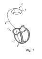
Fig. 1 is a simplified schematic illustration of a medical implant in electrical communication via an implantable lead with a human heart; -
Fig. 2 is a diagram illustrating intracardiac blood temperature variations -
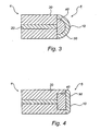
Figs. 3 and 4 are schematic drawings of two embodiments of a tip electrode comprising a temperature sensitive element; an -
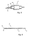
Figs. 5 and 6 are schematic drawings of embodiments of a ring electrode comprising a temperature sensitive element. - The following is a description of exemplifying embodiments in accordance with the present invention. This description is intended for describing the general principles and specific embodiments of the invention and is not to be taken in a limiting sense. Please note that like reference numerals indicate structures or elements having same or similar functions or constructional features.
- Referring first to
Fig. 1 , there is shown animplantable heart stimulator 2 in electrical communication with a human heart 1 via acardiac lead 4 arranged for stimulation and sensing. Moreover, theheart stimulator 2 comprises electronic circuitry and a battery contained within a hermetically sealedpacemaker housing 3. Thehousing 3 comprises a metallic casing of titanium, enclosing the electronic circuitry and battery, and a molded plastic header portion, comprising connector blocks and apertures for receiving the connectors at the proximal ends of the cardiac leads. - The electronic circuitry comprises at least one pulse generator for generating stimulation pulses, sensing circuitry for receiving cardiac signals sensed by the
cardiac lead 20, and a controller. The controller controls both the sensing of cardiac signals and the delivery of stimulation pulses, for instance as to the duration, energy content and timing of the stimulation pulses. - The stimulation pulses generated by the pulse generator are transmitted via the
cardiac lead 4 and delivered to the cardiac tissue by the use of tip electrodes positioned at thedistal end 5 of the cardiac lead. Generally, the tip electrode acts as the cathode when the cardiac pulse is delivered. Furthermore, in unipolar cardiac systems, thecasing 3 acts as the anode, while in bipolar cardiac systems, the anode is provided by an annular orring electrode 7 arranged on the cardiac lead at a small distance from the tip electrode. - It should be noted that even though a
ring electrode 7 is illustrated in the simplified drawing ofFig. 1 , the present invention is equally applicable to unipolar, bipolar, and multipolar systems. Thus, implantable leads with or without ring electrodes are equally contemplated without departing from the scope of the invention. - Furthermore, even though only one
lead 4 for implantation and stimulation in the right ventricle is illustrated in the drawing, themedical implant 2 may be connected to further leads, for instance for sensing and or stimulation of the right atrium, the left atrium, and/or the left ventricle. The leads may comprise sensors for sensing and conducting electrical signals from the heart, and/or sensors for sensing other physiological parameters, such as pressures, temperatures, etc. within the heart. A single electrode or sensor may further be used for multiple purposes, such as delivering electrical stimuli and sensing electrical signals, or sensing electrical signals and pressures, etc. - For the purposes of the presently illustrated embodiments, the
ring electrode 7 and/or thetip electrode 10 may constitute the temperature sensitive element connectable to a device for monitoring the status of an implantable lead in accordance with the present invention. However, other positions on the implantable lead and configurations of the temperature sensitive element are also contemplated without departing from the scope of the present invention. - With reference now to
Fig. 2 , there is shown a diagram illustrating temperature variations in the intraventricular blood stream of a human patient during ventilation. The diagram illustrates both the larger long-term variations occurring within a respiratory cycle, which for the purposes of the illustrated measurements is about 4 seconds, and the smaller short-term variations occurring within a heart beat cycle. The latter can be seen as a ripple on the blood temperature curve. In the illustrated measurements, the long-term variations during a single respiratory cycle, or a single breath, is in the range of 0,03-0,05 °C, and the short-term variations during a single heart beat cycle is in the range of 0,005-0,02 °C. - With reference now to
Figs. 3 and 4 , there is shown thedistal end 5 of animplantable lead 4 for a heart pacemaker, and in particular atip electrode 10 constituting both a stimulating electrode and a temperature sensitive element. Theelectrode 10 comprises aconductor 20 enclosed by aninsulator 30, e.g. made from silicon rubber. Theconductor 20 is at one end in contact with an electricallyconductive core 40, which is covered with apiezoelectric material 50, preferably formed of Na0.5K0.5NbO3- In order to obtain a high capacitance, usually of the order 10-100 nF, the layer of piezoelectric material is very thin (0,1-5 pm). Theconductive core 40 and thepiezoelectric layer 50, i.e. the piezoelectric electrode, form the tip of theimplantable lead 4. -
Figs. 3 and 4 show a hemispherical and a planar embodiment of the tip, respectively, wherein the planar embodiment is more sensitive to how it is placed with respect to the myocardial tissue. In one embodiment, theconductor 20 is made of the commonly used alloy MP35 and theconductive core 40 is made of e.g. graphite, titanium, platinum, or iridium. The size of the electrode is about the same as for standard cardiac stimulator electrodes and may for instance vary between 1-10 mm 2 - Thus, the stimulating or
tip electrode 10 is not only arranged to deliver electrical stimuli to the heart, but is also arranged as a temperature sensitive element capable of providing an output signal indicative of temperature variations occurring in the biological matter in contact with the sensor or electrode surface. - According to another embodiment of an implantable lead comprising a temperature sensitive element,
Figs. 5 and 6 show an annular or coaxial piezoelectric sensor orelectrode 7 constituting a temperature sensitive element. Theannular electrode 7 may be positioned from about 3 mm to 15 cm proximally of the distal end ortip 5, and is intended to be positioned in the intracardiac blood stream when the lead is in the implanted state. This embodiment may e.g. be used in a single lead DDD pacemaker system as disclosed inUS-A-5 476 499 . - In the same manner as described above in relation to
Figs. 3 and 4 , theelectrode 7 comprises aconductor 13 enclosed by an insulator (not shown), e. g. silicon rubber. Theconductor 13 is at one end in contact with an electricallyconductive core 40, which is covered with apiezoelectric material 50, preferably formed of Na0.5K0.5NbO3. In this embodiment, the lead further comprises asecond conductor 12 connected to the temperature sensitive element for enabling an AC vibration exciting current to be applied. - In operation, the temperature sensitive elements are connected to the
heart stimulator 2 for delivering an output signal, or temperature signal, indicative of temperature changes to which the element has been subjected. Electric circuits for measuring such an output signal from the temperature sensitive element are not further described herein since it is well-known to a person skilled in the art how such circuits can be designed. - The stimulator comprises processing circuitry (not shown) for monitoring the status of the implantable lead on the basis of said output signal. The interpretation of the output signal is dependent on several factors, such as the positioning of the sensor on the implantable lead, the intended positioning within the heart, the desired status information, etc.
- As an example, if the temperature sensitive element is arranged at the very tip of the implantable lead, e.g. arranged at or as the stimulating electrode, then the desired status information would be whether the distal end becomes dislocated from an ingrown or embedded position. Thus, it would be desirable to detect a sudden or slow but significant increase in temperature variations which could indicate that dislocation has occurred.
- As a further example, if the temperature sensitive element is arranged at a location on the implantable lead which is intended to be located in the blood stream, e.g. at or as a sensor for measuring parameters of the blood, then a desired status information could be to detect whether the element has come into contact with the ventricular or atrial wall, or whether the element is subjected to overgrowth. Both of these status changes could possibly have an impairing effect on the sensing ability of the sensor.
- According to specific embodiments, which do not constitute part of the invention, the temperature sensitive element could be arranged to have self-cleaning properties. In these embodiments, the element is made from a piezoelectric material which is caused to vibrate upon applying an AC vibrating voltage across the element. This can for instance be performed periodically in order to prevent detrimental build-up of adhering substances to the surface of the element. In another example, the vibrating voltage for removing adhering and clotting substances could be applied following the determination of suspected tissue overgrowth, i.e. when the output signal of the temperature sensitive element indicates a decrease or changed morphology in the temperature variations experienced by the element within a respiratory cycle.
- While the invention disclosed herein has been described by means of specific embodiments and applications thereof, numerous modifications and variations could be made therein by those skilled in the art without departing from the scope of the invention, which is defined by the appended claims.
Claims (14)
- A device for monitoring the status of a cardiac lead (4) implanted in a human heart (1), wherein said device is connectable to at least one temperature sensitive element (50) in said implantable lead (4), said temperature sensitive element (50) being sensitive to the temperature of biological matter in contact with the surface of said temperature sensitive element (50), comprising processing circuitry arranged for:receiving a temperature signal from said temperature sensitive element (50), said temperature signal being indicative of the temperature of said biological matter;determining a temperature signal variability in the temperature signal within a selected time interval, said signal variability being indicative of the temperature variability of said biological matter within said selected time interval; andproviding a status signal indicative of the status of the implantable lead (4) on the basis of the determined temperature signal variability, characterized in that said selected time interval is a respiration cycle of said human.
- The device as claimed in claim 1, wherein said processing circuitry is further arranged for comparing said temperature signal variability with at least one threshold value related to temperature changes occurring in the blood within the heart during said respiration cycle, and
wherein said status signal is based on the results of said comparison. - The device as claimed in claim 1 or 2, wherein said status signal is indicative of whether and/or to what extent the surface of said temperature sensitive element (50) is in contact with blood.
- The device as claimed in any one of claims 1-3, wherein the status signal is indicative of whether the implantable lead (4) has been at least partly dislocated from its implanted position.
- The device as claimed in claim 4, wherein the status signal indicates an at least partial dislocation of a portion of the implantable lead (4), preferably a distal end portion (5) thereof, that has previously been subjected to ingrowth to myocardial tissue.
- The device as claimed in claim 5, wherein the status signal indicates said at least partial dislocation upon a detected sudden and significant rise in the temperature signal variability.
- The device as claimed in any one of claims 1-6, wherein the status signal is indicative of the extent of ingrowth of at least a portion of the implantable lead (4), preferably a distal end portion (5), into the myocardial tissue.
- The device as claimed in claim 7, wherein the processing circuitry is arranged for monitoring the progression of said ingrowth following implantation by comparing the status signals obtained at successive points of time.
- The device as claimed in any one of claims 1-8, wherein the status signal is indicative of the extent to which said temperature sensitive element (50) of the implantable lead (4) has been subjected to undesired tissue overgrowth and protein adherence.
- An implantable cardiac stimulator (2) for delivering stimulation pulses to a human heart (1), comprising:a housing (3);a pulse generator enclosed in said housing (3) for generating said stimulation pulses;control circuitry for controlling the delivery of said stimulation pulses to the heart (1);said stimulator being connectable to a cardiac lead arrangement for conducting said stimulation pulses to the heart (1), and for conducting electrical signals from the heart (1) to the control circuitry, said lead arrangement comprising an implantable lead (4) arranged with a temperature sensitive element (50) that is sensitive to the temperature of biological matter in contact with the surface of said temperature sensitive element (50); anda device for monitoring the status of the cardiac lead (4) as claimed in any one of the preceding claims.
- A cardiac therapy system for delivering stimulation pulses to a human heart (1), comprising:an implantable cardiac stimulator (2) as claimed in claim 10, anda cardiac lead arrangement for conducting said stimulation pulses to the heart (1), and for conducting electrical signals from the heart (1) to the control circuitry, said lead arrangement comprising an implantable lead (4) arranged with a temperature sensitive element (50) that is sensitive to the temperature of biological matter in contact with the surface of said temperature sensitive element (50).
- The system as claimed in claim 11, wherein said temperature sensitive element (50) is arranged at the distal end (5) of the implantable lead (4), such that ingrowth of the distal end (5) of the implantable lead (4) into myocardial tissue is intended to result in an ingrowth of the temperature sensitive element (50).
- The system as claimed in claim 11, wherein said temperature sensitive element (50) is arranged at a distance from the distal end (5) of the implantable lead (4), such that ingrowth of the distal end (5) of the implantable lead (4) into myocardial tissue is not intended to result in an ingrowth of the temperature sensitive element (50).
- The system as claimed in any one of claims 11-13, wherein said temperature sensitive element (50) is arranged on said implantable lead (4) as an essentially annular sensor element.
Applications Claiming Priority (1)
| Application Number | Priority Date | Filing Date | Title |
|---|---|---|---|
| PCT/SE2006/000142 WO2007089175A1 (en) | 2006-01-31 | 2006-01-31 | Implantable cardiac stimulator, device and system for monitoring the status of a cardiac lead |
Publications (3)
| Publication Number | Publication Date |
|---|---|
| EP1981588A1 EP1981588A1 (en) | 2008-10-22 |
| EP1981588A4 EP1981588A4 (en) | 2010-03-31 |
| EP1981588B1 true EP1981588B1 (en) | 2011-11-23 |
Family
ID=38327666
Family Applications (1)
| Application Number | Title | Priority Date | Filing Date |
|---|---|---|---|
| EP06704293A Expired - Lifetime EP1981588B1 (en) | 2006-01-31 | 2006-01-31 | Implantable cardiac stimulator, device and system for monitoring the status of a cardiac lead |
Country Status (4)
| Country | Link |
|---|---|
| US (1) | US8224421B2 (en) |
| EP (1) | EP1981588B1 (en) |
| AT (1) | ATE534430T1 (en) |
| WO (1) | WO2007089175A1 (en) |
Families Citing this family (16)
| Publication number | Priority date | Publication date | Assignee | Title |
|---|---|---|---|---|
| US8825158B2 (en) | 2009-08-25 | 2014-09-02 | Lamda Nu, Llc | Method and apparatus for detection of lead conductor anomalies using dynamic electrical parameters |
| US9205268B2 (en) * | 2009-10-30 | 2015-12-08 | Medtronic, Inc. | Configuring operating parameters of a medical device based on a type of source of a disruptive energy field |
| US9958515B2 (en) * | 2009-10-30 | 2018-05-01 | Medtronic, Inc. | Configuring operating parameters of a medical device based on a type of source of a disruptive energy field |
| US9919158B2 (en) * | 2009-12-29 | 2018-03-20 | Medtronic, Inc. | Configuring operating parameters of a medical device based on exposure to a disruptive energy field |
| US8679010B2 (en) * | 2010-07-16 | 2014-03-25 | Dyconex Ag | Implantable sensor device |
| US8812103B2 (en) | 2012-06-01 | 2014-08-19 | Lamda Nu, Llc | Method for detecting and treating insulation lead-to-housing failures |
| US9272150B2 (en) | 2012-06-01 | 2016-03-01 | Lambda Nu Technology Llc | Method for detecting and localizing insulation failures of implantable device leads |
| US9675799B2 (en) | 2012-12-05 | 2017-06-13 | Lambda Nu Technology Llc | Method and apparatus for implantable cardiac lead integrity analysis |
| US10039919B2 (en) | 2013-04-30 | 2018-08-07 | Lambda Nu Technology Llc | Methods and apparatus for detecting and localizing partial conductor failures of implantable device leads |
| US9486624B2 (en) | 2013-06-13 | 2016-11-08 | Lambda Nu Technology Llc | Detection of implantable lead failures by differential EGM analysis |
| US10118031B2 (en) | 2013-06-28 | 2018-11-06 | Lambda Nu Technology Llc | Method and apparatus for implantable cardiac lead integrity analysis |
| US9958339B2 (en) * | 2014-02-07 | 2018-05-01 | Boston Scientific Neuromodulation Corporation | Temperature sensing circuitry for an implantable medical device |
| US9636500B2 (en) | 2014-03-25 | 2017-05-02 | Lambda Nu Technology Llc | Active surveillance of implanted medical leads for lead integrity |
| US10252069B1 (en) | 2015-11-19 | 2019-04-09 | Lambda Nu Technology Llc | Micro-charge ICD lead testing method and apparatus |
| US10543364B2 (en) | 2017-04-07 | 2020-01-28 | Lambda Nu Technology Llc | Detection of lead electrode dislodgement using cavitary electrogram |
| WO2025095934A1 (en) * | 2023-10-31 | 2025-05-08 | Chelak Medical Solutions Inc. | Systems, devices, and methods of temperature compensation in fiber bragg grating sensing systems in implantable devices |
Family Cites Families (11)
| Publication number | Priority date | Publication date | Assignee | Title |
|---|---|---|---|---|
| US5336244A (en) * | 1992-10-07 | 1994-08-09 | Medtronic, Inc. | Temperature sensor based capture detection for a pacer |
| DE69433213T2 (en) * | 1993-11-10 | 2004-05-06 | Medtronic, Inc., Minneapolis | Catheter with electrode arrangement |
| US5520190A (en) * | 1994-10-31 | 1996-05-28 | Ventritex, Inc. | Cardiac blood flow sensor and method |
| US5596995A (en) * | 1995-05-02 | 1997-01-28 | Heart Rhythm Technologies, Inc. | Biomedical device having a temperature sensing system |
| US6063078A (en) * | 1997-03-12 | 2000-05-16 | Medtronic, Inc. | Method and apparatus for tissue ablation |
| US5989192A (en) * | 1997-09-25 | 1999-11-23 | Medtronic, Inc. | Cardiac flow sensor |
| SE9801405D0 (en) * | 1998-04-22 | 1998-04-22 | Pacesetter Ab | Implant |
| ATE305264T1 (en) * | 2000-07-22 | 2005-10-15 | Biotronik Mess & Therapieg | IMPLANTABLE MEASURING DEVICE, IN PARTICULAR PRESSURE MEASURING DEVICE FOR DETERMINING INTRACARDIAL OR INTRALUMINAL BLOOD PRESSURE |
| US20020103429A1 (en) * | 2001-01-30 | 2002-08-01 | Decharms R. Christopher | Methods for physiological monitoring, training, exercise and regulation |
| WO2006135293A1 (en) | 2005-06-16 | 2006-12-21 | St. Jude Medical Ab | Flow sensor and method for measuring the flow of a body fluid |
| US8348855B2 (en) * | 2005-08-29 | 2013-01-08 | Galil Medical Ltd. | Multiple sensor device for measuring tissue temperature during thermal treatment |
-
2006
- 2006-01-31 US US12/160,970 patent/US8224421B2/en not_active Expired - Fee Related
- 2006-01-31 EP EP06704293A patent/EP1981588B1/en not_active Expired - Lifetime
- 2006-01-31 WO PCT/SE2006/000142 patent/WO2007089175A1/en not_active Ceased
- 2006-01-31 AT AT06704293T patent/ATE534430T1/en active
Also Published As
| Publication number | Publication date |
|---|---|
| US20090306735A1 (en) | 2009-12-10 |
| US8224421B2 (en) | 2012-07-17 |
| EP1981588A4 (en) | 2010-03-31 |
| WO2007089175A1 (en) | 2007-08-09 |
| EP1981588A1 (en) | 2008-10-22 |
| ATE534430T1 (en) | 2011-12-15 |
Similar Documents
| Publication | Publication Date | Title |
|---|---|---|
| US7493174B2 (en) | Implantable medical lead | |
| US9522276B2 (en) | Accelerometer integrity alert | |
| US8224421B2 (en) | Implantable cardiac stimulator, device and system for monitoring the status of a cardiac lead | |
| CN109789308B (en) | Atrial tracking in an intracardiac ventricular pacemaker | |
| US8903492B2 (en) | Ion imbalance detector | |
| EP3432976B1 (en) | Atrial tracking in an intracardiac ventricular pacemaker | |
| US5824029A (en) | Implantable medical system for performing transthoracic impedance measurements associated with cardiac function | |
| CN107106848B (en) | Leadless pacing system with mode switching capability via ventricular leadless pacing device | |
| US5935158A (en) | Electrode lead and device for tissue stimulation and/or detection of tissue response | |
| CN116531667A (en) | Atrial tracking in an intracardiac ventricular pacemaker | |
| US6571130B1 (en) | Medical implant with piezoelectric material in contact with body tissue | |
| US20090024054A1 (en) | Implantable medical device | |
| JP2013539713A (en) | Temperature sensor for leadless cardiac pacemakers | |
| JPH11500930A (en) | Implantable medical device with sealed physiological parameter sensor or telemetry link | |
| JPS62270172A (en) | Heart conditioning lead wire assembly and method | |
| WO1999042169A1 (en) | Implantable biocompatible electrode for both electrically and mechanically stimulating the tissue | |
| WO2006118762A1 (en) | Method and apparatus for dynamically monitoring, detecting and diagnosing lead conditions | |
| US8271085B2 (en) | Implantable medical device for blood conductivity, blood impedance, and/or hematocrit measurement | |
| CN107548313B (en) | Use acceleration to monitor pace capture | |
| CN110831659A (en) | Atrial tracking confirmation in an intracardiac ventricular pacemaker | |
| US8781587B2 (en) | Detecting and treatment of sleep apnea | |
| CN108136185B (en) | Apparatus and method for adjusting pacing rate in an implantable medical device | |
| JP2020534099A (en) | Implantable medical device with multiple modes of operation | |
| JPH09215758A (en) | Pacemaker device | |
| EP2152362B1 (en) | Implantable medical device for monitoring lung deficiency |
Legal Events
| Date | Code | Title | Description |
|---|---|---|---|
| PUAI | Public reference made under article 153(3) epc to a published international application that has entered the european phase |
Free format text: ORIGINAL CODE: 0009012 |
|
| 17P | Request for examination filed |
Effective date: 20080901 |
|
| AK | Designated contracting states |
Kind code of ref document: A1 Designated state(s): AT BE BG CH CY CZ DE DK EE ES FI FR GB GR HU IE IS IT LI LT LU LV MC NL PL PT RO SE SI SK TR |
|
| A4 | Supplementary search report drawn up and despatched |
Effective date: 20100225 |
|
| RIC1 | Information provided on ipc code assigned before grant |
Ipc: A61N 1/362 20060101ALI20101220BHEP Ipc: G01K 7/00 20060101ALI20101220BHEP Ipc: A61N 1/37 20060101AFI20101220BHEP Ipc: A61N 1/39 20060101ALI20101220BHEP |
|
| GRAP | Despatch of communication of intention to grant a patent |
Free format text: ORIGINAL CODE: EPIDOSNIGR1 |
|
| DAX | Request for extension of the european patent (deleted) | ||
| GRAS | Grant fee paid |
Free format text: ORIGINAL CODE: EPIDOSNIGR3 |
|
| GRAA | (expected) grant |
Free format text: ORIGINAL CODE: 0009210 |
|
| AK | Designated contracting states |
Kind code of ref document: B1 Designated state(s): AT BE BG CH CY CZ DE DK EE ES FI FR GB GR HU IE IS IT LI LT LU LV MC NL PL PT RO SE SI SK TR |
|
| REG | Reference to a national code |
Ref country code: GB Ref legal event code: FG4D |
|
| REG | Reference to a national code |
Ref country code: CH Ref legal event code: EP |
|
| REG | Reference to a national code |
Ref country code: IE Ref legal event code: FG4D |
|
| REG | Reference to a national code |
Ref country code: DE Ref legal event code: R096 Ref document number: 602006025994 Country of ref document: DE Effective date: 20120202 |
|
| REG | Reference to a national code |
Ref country code: NL Ref legal event code: VDEP Effective date: 20111123 |
|
| LTIE | Lt: invalidation of european patent or patent extension |
Effective date: 20111123 |
|
| PG25 | Lapsed in a contracting state [announced via postgrant information from national office to epo] |
Ref country code: IS Free format text: LAPSE BECAUSE OF FAILURE TO SUBMIT A TRANSLATION OF THE DESCRIPTION OR TO PAY THE FEE WITHIN THE PRESCRIBED TIME-LIMIT Effective date: 20120323 Ref country code: LT Free format text: LAPSE BECAUSE OF FAILURE TO SUBMIT A TRANSLATION OF THE DESCRIPTION OR TO PAY THE FEE WITHIN THE PRESCRIBED TIME-LIMIT Effective date: 20111123 |
|
| PG25 | Lapsed in a contracting state [announced via postgrant information from national office to epo] |
Ref country code: SE Free format text: LAPSE BECAUSE OF FAILURE TO SUBMIT A TRANSLATION OF THE DESCRIPTION OR TO PAY THE FEE WITHIN THE PRESCRIBED TIME-LIMIT Effective date: 20111123 Ref country code: NL Free format text: LAPSE BECAUSE OF FAILURE TO SUBMIT A TRANSLATION OF THE DESCRIPTION OR TO PAY THE FEE WITHIN THE PRESCRIBED TIME-LIMIT Effective date: 20111123 Ref country code: PT Free format text: LAPSE BECAUSE OF FAILURE TO SUBMIT A TRANSLATION OF THE DESCRIPTION OR TO PAY THE FEE WITHIN THE PRESCRIBED TIME-LIMIT Effective date: 20120323 Ref country code: BE Free format text: LAPSE BECAUSE OF FAILURE TO SUBMIT A TRANSLATION OF THE DESCRIPTION OR TO PAY THE FEE WITHIN THE PRESCRIBED TIME-LIMIT Effective date: 20111123 Ref country code: GR Free format text: LAPSE BECAUSE OF FAILURE TO SUBMIT A TRANSLATION OF THE DESCRIPTION OR TO PAY THE FEE WITHIN THE PRESCRIBED TIME-LIMIT Effective date: 20120224 Ref country code: SI Free format text: LAPSE BECAUSE OF FAILURE TO SUBMIT A TRANSLATION OF THE DESCRIPTION OR TO PAY THE FEE WITHIN THE PRESCRIBED TIME-LIMIT Effective date: 20111123 Ref country code: LV Free format text: LAPSE BECAUSE OF FAILURE TO SUBMIT A TRANSLATION OF THE DESCRIPTION OR TO PAY THE FEE WITHIN THE PRESCRIBED TIME-LIMIT Effective date: 20111123 |
|
| PG25 | Lapsed in a contracting state [announced via postgrant information from national office to epo] |
Ref country code: CY Free format text: LAPSE BECAUSE OF FAILURE TO SUBMIT A TRANSLATION OF THE DESCRIPTION OR TO PAY THE FEE WITHIN THE PRESCRIBED TIME-LIMIT Effective date: 20111123 |
|
| PG25 | Lapsed in a contracting state [announced via postgrant information from national office to epo] |
Ref country code: DK Free format text: LAPSE BECAUSE OF FAILURE TO SUBMIT A TRANSLATION OF THE DESCRIPTION OR TO PAY THE FEE WITHIN THE PRESCRIBED TIME-LIMIT Effective date: 20111123 Ref country code: SK Free format text: LAPSE BECAUSE OF FAILURE TO SUBMIT A TRANSLATION OF THE DESCRIPTION OR TO PAY THE FEE WITHIN THE PRESCRIBED TIME-LIMIT Effective date: 20111123 Ref country code: EE Free format text: LAPSE BECAUSE OF FAILURE TO SUBMIT A TRANSLATION OF THE DESCRIPTION OR TO PAY THE FEE WITHIN THE PRESCRIBED TIME-LIMIT Effective date: 20111123 Ref country code: BG Free format text: LAPSE BECAUSE OF FAILURE TO SUBMIT A TRANSLATION OF THE DESCRIPTION OR TO PAY THE FEE WITHIN THE PRESCRIBED TIME-LIMIT Effective date: 20120223 Ref country code: CZ Free format text: LAPSE BECAUSE OF FAILURE TO SUBMIT A TRANSLATION OF THE DESCRIPTION OR TO PAY THE FEE WITHIN THE PRESCRIBED TIME-LIMIT Effective date: 20111123 |
|
| PG25 | Lapsed in a contracting state [announced via postgrant information from national office to epo] |
Ref country code: RO Free format text: LAPSE BECAUSE OF FAILURE TO SUBMIT A TRANSLATION OF THE DESCRIPTION OR TO PAY THE FEE WITHIN THE PRESCRIBED TIME-LIMIT Effective date: 20111123 Ref country code: MC Free format text: LAPSE BECAUSE OF NON-PAYMENT OF DUE FEES Effective date: 20120131 Ref country code: IT Free format text: LAPSE BECAUSE OF FAILURE TO SUBMIT A TRANSLATION OF THE DESCRIPTION OR TO PAY THE FEE WITHIN THE PRESCRIBED TIME-LIMIT Effective date: 20111123 Ref country code: PL Free format text: LAPSE BECAUSE OF FAILURE TO SUBMIT A TRANSLATION OF THE DESCRIPTION OR TO PAY THE FEE WITHIN THE PRESCRIBED TIME-LIMIT Effective date: 20111123 |
|
| REG | Reference to a national code |
Ref country code: AT Ref legal event code: MK05 Ref document number: 534430 Country of ref document: AT Kind code of ref document: T Effective date: 20111123 |
|
| PLBE | No opposition filed within time limit |
Free format text: ORIGINAL CODE: 0009261 |
|
| STAA | Information on the status of an ep patent application or granted ep patent |
Free format text: STATUS: NO OPPOSITION FILED WITHIN TIME LIMIT |
|
| GBPC | Gb: european patent ceased through non-payment of renewal fee |
Effective date: 20120223 |
|
| REG | Reference to a national code |
Ref country code: IE Ref legal event code: MM4A |
|
| 26N | No opposition filed |
Effective date: 20120824 |
|
| REG | Reference to a national code |
Ref country code: DE Ref legal event code: R097 Ref document number: 602006025994 Country of ref document: DE Effective date: 20120824 |
|
| PG25 | Lapsed in a contracting state [announced via postgrant information from national office to epo] |
Ref country code: AT Free format text: LAPSE BECAUSE OF FAILURE TO SUBMIT A TRANSLATION OF THE DESCRIPTION OR TO PAY THE FEE WITHIN THE PRESCRIBED TIME-LIMIT Effective date: 20111123 Ref country code: GB Free format text: LAPSE BECAUSE OF NON-PAYMENT OF DUE FEES Effective date: 20120223 Ref country code: IE Free format text: LAPSE BECAUSE OF NON-PAYMENT OF DUE FEES Effective date: 20120131 |
|
| PG25 | Lapsed in a contracting state [announced via postgrant information from national office to epo] |
Ref country code: ES Free format text: LAPSE BECAUSE OF FAILURE TO SUBMIT A TRANSLATION OF THE DESCRIPTION OR TO PAY THE FEE WITHIN THE PRESCRIBED TIME-LIMIT Effective date: 20120305 |
|
| PGFP | Annual fee paid to national office [announced via postgrant information from national office to epo] |
Ref country code: CH Payment date: 20130125 Year of fee payment: 8 |
|
| PG25 | Lapsed in a contracting state [announced via postgrant information from national office to epo] |
Ref country code: FI Free format text: LAPSE BECAUSE OF FAILURE TO SUBMIT A TRANSLATION OF THE DESCRIPTION OR TO PAY THE FEE WITHIN THE PRESCRIBED TIME-LIMIT Effective date: 20111123 |
|
| PG25 | Lapsed in a contracting state [announced via postgrant information from national office to epo] |
Ref country code: TR Free format text: LAPSE BECAUSE OF FAILURE TO SUBMIT A TRANSLATION OF THE DESCRIPTION OR TO PAY THE FEE WITHIN THE PRESCRIBED TIME-LIMIT Effective date: 20111123 |
|
| PG25 | Lapsed in a contracting state [announced via postgrant information from national office to epo] |
Ref country code: LU Free format text: LAPSE BECAUSE OF NON-PAYMENT OF DUE FEES Effective date: 20120131 |
|
| PG25 | Lapsed in a contracting state [announced via postgrant information from national office to epo] |
Ref country code: HU Free format text: LAPSE BECAUSE OF FAILURE TO SUBMIT A TRANSLATION OF THE DESCRIPTION OR TO PAY THE FEE WITHIN THE PRESCRIBED TIME-LIMIT Effective date: 20060131 |
|
| REG | Reference to a national code |
Ref country code: CH Ref legal event code: PL |
|
| PG25 | Lapsed in a contracting state [announced via postgrant information from national office to epo] |
Ref country code: CH Free format text: LAPSE BECAUSE OF NON-PAYMENT OF DUE FEES Effective date: 20140131 Ref country code: LI Free format text: LAPSE BECAUSE OF NON-PAYMENT OF DUE FEES Effective date: 20140131 |
|
| REG | Reference to a national code |
Ref country code: FR Ref legal event code: PLFP Year of fee payment: 11 |
|
| REG | Reference to a national code |
Ref country code: FR Ref legal event code: PLFP Year of fee payment: 12 |
|
| REG | Reference to a national code |
Ref country code: FR Ref legal event code: PLFP Year of fee payment: 13 |
|
| PGFP | Annual fee paid to national office [announced via postgrant information from national office to epo] |
Ref country code: FR Payment date: 20201223 Year of fee payment: 16 |
|
| PGFP | Annual fee paid to national office [announced via postgrant information from national office to epo] |
Ref country code: DE Payment date: 20201218 Year of fee payment: 16 |
|
| REG | Reference to a national code |
Ref country code: DE Ref legal event code: R119 Ref document number: 602006025994 Country of ref document: DE |
|
| PG25 | Lapsed in a contracting state [announced via postgrant information from national office to epo] |
Ref country code: DE Free format text: LAPSE BECAUSE OF NON-PAYMENT OF DUE FEES Effective date: 20220802 |
|
| PG25 | Lapsed in a contracting state [announced via postgrant information from national office to epo] |
Ref country code: FR Free format text: LAPSE BECAUSE OF NON-PAYMENT OF DUE FEES Effective date: 20220131 |
|
| P01 | Opt-out of the competence of the unified patent court (upc) registered |
Effective date: 20230602 |