EP1978845B1 - Anti-rattle track fastener - Google Patents
Anti-rattle track fastener Download PDFInfo
- Publication number
- EP1978845B1 EP1978845B1 EP07797102.6A EP07797102A EP1978845B1 EP 1978845 B1 EP1978845 B1 EP 1978845B1 EP 07797102 A EP07797102 A EP 07797102A EP 1978845 B1 EP1978845 B1 EP 1978845B1
- Authority
- EP
- European Patent Office
- Prior art keywords
- cam
- track
- stud
- slot
- rattle
- Prior art date
- Legal status (The legal status is an assumption and is not a legal conclusion. Google has not performed a legal analysis and makes no representation as to the accuracy of the status listed.)
- Not-in-force
Links
- 238000000034 method Methods 0.000 claims description 5
- DHKHKXVYLBGOIT-UHFFFAOYSA-N acetaldehyde Diethyl Acetal Natural products CCOC(C)OCC DHKHKXVYLBGOIT-UHFFFAOYSA-N 0.000 description 3
- 125000002777 acetyl group Chemical class [H]C([H])([H])C(*)=O 0.000 description 3
- 229920006026 co-polymeric resin Polymers 0.000 description 3
- 238000009434 installation Methods 0.000 description 2
- 239000002184 metal Substances 0.000 description 2
- 229910052751 metal Inorganic materials 0.000 description 2
- 229920004943 Delrin® Polymers 0.000 description 1
- 230000000712 assembly Effects 0.000 description 1
- 238000000429 assembly Methods 0.000 description 1
- 239000000463 material Substances 0.000 description 1
- 230000013011 mating Effects 0.000 description 1
- 239000007769 metal material Substances 0.000 description 1
- 150000002739 metals Chemical class 0.000 description 1
- 229920003023 plastic Polymers 0.000 description 1
- 239000004033 plastic Substances 0.000 description 1
- 239000004810 polytetrafluoroethylene Substances 0.000 description 1
- 229920001343 polytetrafluoroethylene Polymers 0.000 description 1
- 229920005989 resin Polymers 0.000 description 1
- 239000011347 resin Substances 0.000 description 1
- 230000000284 resting effect Effects 0.000 description 1
- 230000000717 retained effect Effects 0.000 description 1
Images


Classifications
-
- B—PERFORMING OPERATIONS; TRANSPORTING
- B64—AIRCRAFT; AVIATION; COSMONAUTICS
- B64D—EQUIPMENT FOR FITTING IN OR TO AIRCRAFT; FLIGHT SUITS; PARACHUTES; ARRANGEMENT OR MOUNTING OF POWER PLANTS OR PROPULSION TRANSMISSIONS IN AIRCRAFT
- B64D11/00—Passenger or crew accommodation; Flight-deck installations not otherwise provided for
- B64D11/06—Arrangements of seats, or adaptations or details specially adapted for aircraft seats
- B64D11/0696—Means for fastening seats to floors, e.g. to floor rails
-
- B—PERFORMING OPERATIONS; TRANSPORTING
- B60—VEHICLES IN GENERAL
- B60N—SEATS SPECIALLY ADAPTED FOR VEHICLES; VEHICLE PASSENGER ACCOMMODATION NOT OTHERWISE PROVIDED FOR
- B60N2/00—Seats specially adapted for vehicles; Arrangement or mounting of seats in vehicles
- B60N2/005—Arrangement or mounting of seats in vehicles, e.g. dismountable auxiliary seats
- B60N2/015—Attaching seats directly to vehicle chassis
- B60N2/01508—Attaching seats directly to vehicle chassis using quick release attachments
- B60N2/01516—Attaching seats directly to vehicle chassis using quick release attachments with locking mechanisms
- B60N2/01558—Attaching seats directly to vehicle chassis using quick release attachments with locking mechanisms with key and slot
- B60N2/01575—Attaching seats directly to vehicle chassis using quick release attachments with locking mechanisms with key and slot key sliding inside the vehicle floor or rail
-
- B—PERFORMING OPERATIONS; TRANSPORTING
- B61—RAILWAYS
- B61D—BODY DETAILS OR KINDS OF RAILWAY VEHICLES
- B61D33/00—Seats
- B61D33/0057—Seats characterised by their mounting in vehicles
-
- B—PERFORMING OPERATIONS; TRANSPORTING
- B60—VEHICLES IN GENERAL
- B60N—SEATS SPECIALLY ADAPTED FOR VEHICLES; VEHICLE PASSENGER ACCOMMODATION NOT OTHERWISE PROVIDED FOR
- B60N2205/00—General mechanical or structural details
- B60N2205/20—Measures for elimination or compensation of play or backlash
Definitions
- This invention relates to a track fastener assembly of the type used to anchor seats or cargo to tracks fitted to the floor of a vehicle.
- the particular embodiment disclosed herein is of a track fastener assembly for securing an aircraft passenger seating unit to the floor of an aircraft. Therefore, the vehicle referred to throughout this application is an aircraft. It is understood that the invention relates as well to other types of vehicles such as trains, buses, or the like.
- aircraft require the capability to be differently configured to meet varying cargo and/or passenger-carrying requirements such as the removal or addition of passenger seats and/or cargo.
- aircraft also must have the capability to easily and quickly relocate or reposition seats and/or cargo. It is often necessary in aircraft to change the spacing between seats to increase or decrease the passenger density throughout a portion of or the entire aircraft. For example, it may be necessary to change the passenger density of a particular aircraft from its normal first class and coach density to an all-coach configuration such as might be necessary with charter operations.
- some aircraft particularly those operating on late-night schedules, carry both passengers and cargo, the cargo being carried in one or more compartments normally used to carry passengers. Also driving this design is the need of aircraft manufacturers to speed their initial installation time, which is a major consideration on large aircraft with many seats.
- locking tracks that run fore and aft along the deck of the major compartments of the aircraft.
- These locking tracks have a slot that runs the entire length of the track along its top side.
- Enlarged cut-out openings are spaced at regular intervals along the length of the track to receive track fasteners to permit the track fasteners to be positioned along and locked into the track in order to secure passenger seats and/or cargo pallets that are themselves secured to the track fastener.
- track fasteners are adjustable within the track, thereby permitting the seats and/or cargo to be repositioned or removed.
- the locking tracks and track fasteners are both fabricated from metal materials. Even when tightly locked into place, adjacent metal parts can rattle, causing annoying disturbances within an aircraft cabin environment. In an effort to reduce rattling there may be a tendency to over-tighten the track fastener screws. This can potentially lead to damaged screws, stripped threads and jamming of the fastener that makes later removal difficult.
- Prior art anti-rattle devices include star-shaped washers that are threaded down onto the front stud shaft of the track fastener to lift the seat slightly off of the track and snug-up the front stud onto the bottom of the track surface. These washers are difficult and time-consuming to install, and require special tools.
- US 4,213,593 discloses a track member secured to the floor of a vehicle.
- the track member having a longitudinally extending slot communicating with an interior channel, a cover member including a top portion and a pair of downwardly projecting ribs having means at the bottom thereof for latchingly engaging the bottom edge of the slot and a vehicular seat which is to be releasably secured to the track member comprising a leg and a locking assembly secured thereto including a pivotally mounted control lever selectively displaceable from an elevated release position to a lowered locking position, the lever, when at the locking position, having a portion projecting upwardly above the track member having a width and a height of elevation selected so that the upwardly projecting portion will fit within the volume defined by the top and downwardly projecting ribs of the cover member, the cover member comprising means for containing and concealing from view the upwardly projecting lever portion.
- US 2,779,092 discloses a clamp locator block which is fastened to the top and side plates of an out-rigger at the end edges.
- the bottom plate of the out-rigger connects to a gusset which joins the plates and the block.
- the block has a circular central hole with upper and lower opposed radial slots.
- the present invention quickly and efficiently locks the track fastener into its proper position, prevents rattling and vibration that causes irritating noise and may loosen the track fitting.
- an object of the invention to provide an anti-rattle track fastener assembly for a vehicle such as an aircraft, train, bus or the like.
- an anti-rattle track fastener assembly for attaching a fixture to a vehicle that has a track formed therein.
- the track includes upper walls that form a longitudinally-extending slot. Spaced-apart segments extend from the upper walls into the slot to provide undercut areas in the slot positioned underthe segments. Spaced-apart openings are positioned between the segments.
- the fastener assembly includes a stud that extends from the fixture and is dimensioned to be received within the slot for engaging the spaced-apart segments.
- the fastener also includes a cam located fore or aft of the stud, the cam having a tranversely-extending, eccentrically-positioned hole therethrough for mounting the cam to the fixture and is movable between a first position and a second position.
- the cam When the cam is in the first position, the stud is engageable to the spaced-apart segments with clearance, and when the cam is in the second position, the stud is tightly engageable to the spaced- apart segments against movement of the fixture.
- the cam also has a radially extending camming hole formed therein for receiving a tool for moving the cam between the first position and the second position.
- the stud has a foot for engaging the spaced-apart segments formed on an end thereof.
- the cam has a curved surface.
- the cam has a flat surface portion.
- the fastener assembly includes a foot formed on the stud for being received within the slot and the flat surface portion is dimensioned to engage the track when the cam is in the first position and the foot is received within the slot.
- the cam is dimensioned such that the flat surface portion is positioned away from the track when the cam is in the second position and the foot is received within the slot.
- the stud is dimensioned to be received within a sleeve.
- the sleeve is dimensioned to be attached to the fixture.
- the fixture is a seat for passengers within an airplane.
- a method relating to an anti-rattle track fastener assembly for attaching a fixture to a vehicle including the step of providing a track having upper walls that form a longitudinally- extending slot and having spaced-apart segments that extend from the upper walls into the slot.
- the spaced-apart segments provide undercut areas in the slot positioned under the segments and spaced-apart openings positioned between the segments.
- the fixture includes a stud that extends from the fixture and is dimensioned to be received within the slot for engaging the spaced-apart segments.
- the fixture also includes a cam located fore or aft of the stud, the cam having a tranversely-extending, eccentrically-positioned hole therethrough for mounting the cam to the fixture.
- the cam is movable between a first position wherein the stud can engage the spaced-apart segments with clearance and a second position wherein the stud can tightly engage the spaced-apart segments.
- the fixture is positioned adjacent the track such that the stud extends into the slot and the cam is in the first position.
- the cam is then moved from the first position to the second position thereby wedging the cam into engagement with the upper walls of the track such that the stud is tightly engaged with the segments.
- the step of positioning the fixture adjacent the track such that the stud extends into the slot includes the step of extending the stud through openings that are positioned between the segments.
- FIG. 1 a typical seating arrangement using the track fastener assembly according to the present invention is illustrated in FIG. 1 .
- a seating unit “S” is positioned on a locking track 11 and locked thereto by means of track fastener assemblies 10 mounted on the front end of the seat legs "L ⁇ B>
- locking track 11 has a longitudinally-extending slot 12 therein that extends along the entire length of the locking track 11.
- Upper walls 13 of the locking track 11 define the slot 12 and have regularly spaced-apart enlarged openings 14 along the length thereof, separated by relatively narrower track slot segments 15 that form the portions of the structure that actually perform the locking function.
- the narrow track slot segments 15 extend into the slot 12 to provide undercut areas in the slot 12 beneath the slot segments 15.
- the enlarged openings 14 have little or no undercut areas in the slot 12.
- the locking track 11 is attached to the floor of the aircraft, for example by machine screws that pass through screw holes, not shown, in the bottom of locking track 11.
- the anti-rattle track fastener assembly 10 includes a track stud 20 having a stud shaft 22 and an enlarged locking foot 24.
- the stud 20 is mounted in a sleeve 26 that is positioned between sidewalls 10A and 10B of the track fastener 10.
- the stud 20 may be formed integrally with the sleeve 26, threaded or welded onto it, or the track stud may be screwed directly into the seat leg "L" by forming mating screw threads in the leg T'.
- Two diametrically-aligned screw holes 28 and 30 accept a screw 32 that is extended through screw holes 34 and 36 in the sidewalls 10A, 10B.
- the screw holes 28 and 30 are aligned with the screw holes 34, 36 by means of a guide pin 38 that fits into a small guide hole 40.
- the screw 32 is secured by a nut 42.
- a cam 50 is positioned between the sidewalls 10A, 10B adjacent the stud
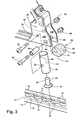
- the cam 50 includes a transversely-extending, eccentrically-positioned screw hole 52, a flat surface portion 54, a curved surface portion 56 and a radially- extending camming hole 58.
- the cam 50 is mounted to the sidewalls 10A, 10B by a screw 60 positioned in a sleeve 62 and positioned in cam mounting holes 64, 66.
- the screw 60 is secured with a nut 68.
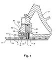
- the track fastener 10 is shown in the mounted position, with the foot 24 of the stud 20 positioned in the slot 12 and displaced from the opening 14 so that the stud 20 is retained the area of one of the relatively narrower track slot segments 15. Note at this point that there is a clearance between the top of the foot 24 and the upper walls 13 of the track 11.
- the cam 50 is positioned with the flat surface area 54 resting on the upper walls 13 of the track 1.1.
- the flat surface area 54 also acts to resist inadvertent disengagement of the cam 50 and disengagement without the use of a tool.
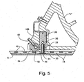
- any suitably sized object such as the shank 62 of a screwdriver
- the cam 50 is rotated so that the flat surface area 54 is rotated away from engagement with the upper walls 13 of the track 11.
- the curved surface portion 56 is wedged into engagement with the upper walls 13 of the track 11.
- the eccentric position of the screw hole 52 and the curved surface portion 56 causes the stud 20 to be raised upwardly as the cam 50 is rotated, wedging the foot 24 of the stud 20 into a tight engagement with the upper walls 13 of the track 11.
- the camming hole 58 can be sized to accept the shank 62 of the screwdriver used to tighten the screws 32 and 60.
- the acetal copolymer resin of the cam 50 has a slight degree of compressibility that allows a secure engagement between the cam 50 and the track 11, while the low CF of the acetal copolymer resin allows the cam 50 to be relatively easily rotated between the positions shown in Figures 4 and 5 .
- a cam is used to wedge the foot 24 of the stud 20 into a tight, non-rattling engagement with the track 11.
- the cam is located before or aft of the track stud and may or may not have a flat side. Eccentric mounting of the cam may provide adequate force on the track, and other means may be used to prevent inadvertent movement of the cam out of the anti-rattle position.
Landscapes
- Engineering & Computer Science (AREA)
- Aviation & Aerospace Engineering (AREA)
- Mechanical Engineering (AREA)
- Transportation (AREA)
- Connection Of Plates (AREA)
- Seats For Vehicles (AREA)
Description
- This application is a formal utility of
U.S. Provisional Patent Application No. 60/766,588 filed on January 3O1 2006 . - This invention relates to a track fastener assembly of the type used to anchor seats or cargo to tracks fitted to the floor of a vehicle. The particular embodiment disclosed herein is of a track fastener assembly for securing an aircraft passenger seating unit to the floor of an aircraft. Therefore, the vehicle referred to throughout this application is an aircraft. It is understood that the invention relates as well to other types of vehicles such as trains, buses, or the like.
- Many aircraft require the capability to be differently configured to meet varying cargo and/or passenger-carrying requirements such as the removal or addition of passenger seats and/or cargo. In addition, aircraft also must have the capability to easily and quickly relocate or reposition seats and/or cargo. It is often necessary in aircraft to change the spacing between seats to increase or decrease the passenger density throughout a portion of or the entire aircraft. For example, it may be necessary to change the passenger density of a particular aircraft from its normal first class and coach density to an all-coach configuration such as might be necessary with charter operations. In addition, some aircraft, particularly those operating on late-night schedules, carry both passengers and cargo, the cargo being carried in one or more compartments normally used to carry passengers. Also driving this design is the need of aircraft manufacturers to speed their initial installation time, which is a major consideration on large aircraft with many seats.
- To provide this capability, aircraft manufacturers install locking tracks that run fore and aft along the deck of the major compartments of the aircraft. These locking tracks have a slot that runs the entire length of the track along its top side. Enlarged cut-out openings are spaced at regular intervals along the length of the track to receive track fasteners to permit the track fasteners to be positioned along and locked into the track in order to secure passenger seats and/or cargo pallets that are themselves secured to the track fastener. These track fasteners are adjustable within the track, thereby permitting the seats and/or cargo to be repositioned or removed.
- The locking tracks and track fasteners are both fabricated from metal materials. Even when tightly locked into place, adjacent metal parts can rattle, causing annoying disturbances within an aircraft cabin environment. In an effort to reduce rattling there may be a tendency to over-tighten the track fastener screws. This can potentially lead to damaged screws, stripped threads and jamming of the fastener that makes later removal difficult. Prior art anti-rattle devices include star-shaped washers that are threaded down onto the front stud shaft of the track fastener to lift the seat slightly off of the track and snug-up the front stud onto the bottom of the track surface. These washers are difficult and time-consuming to install, and require special tools.
-
US 4,213,593 discloses a track member secured to the floor of a vehicle. The track member having a longitudinally extending slot communicating with an interior channel, a cover member including a top portion and a pair of downwardly projecting ribs having means at the bottom thereof for latchingly engaging the bottom edge of the slot and a vehicular seat which is to be releasably secured to the track member comprising a leg and a locking assembly secured thereto including a pivotally mounted control lever selectively displaceable from an elevated release position to a lowered locking position, the lever, when at the locking position, having a portion projecting upwardly above the track member having a width and a height of elevation selected so that the upwardly projecting portion will fit within the volume defined by the top and downwardly projecting ribs of the cover member, the cover member comprising means for containing and concealing from view the upwardly projecting lever portion. -
US 2,779,092 discloses a clamp locator block which is fastened to the top and side plates of an out-rigger at the end edges. The bottom plate of the out-rigger connects to a gusset which joins the plates and the block. The block has a circular central hole with upper and lower opposed radial slots. - The present invention quickly and efficiently locks the track fastener into its proper position, prevents rattling and vibration that causes irritating noise and may loosen the track fitting.
- Therefore, it is an object of the invention to provide an anti-rattle track fastener assembly for a vehicle such as an aircraft, train, bus or the like.
- It is an object of the invention to provide an anti-rattle track fastener assembly that is quickly and easily locked and unlocked when necessary to reposition the fastener.
- It is another object of the invention to provide an anti-rattle track fastener assembly that is capable of being engaged to a locking track quickly, safely and securely.
- It is another object of the invention to provide an anti-rattle track fastener assembly that does not require special tools.
- It is another object of the invention to provide an anti-rattle track fastener assembly that does not interfere with or require attachment to the stud shaft of the track fastener.
- According to one embodiment of the present invention, there is provided an anti-rattle track fastener assembly for attaching a fixture to a vehicle that has a track formed therein. The track includes upper walls that form a longitudinally-extending slot. Spaced-apart segments extend from the upper walls into the slot to provide undercut areas in the slot positioned underthe segments. Spaced-apart openings are positioned between the segments. The fastener assembly includes a stud that extends from the fixture and is dimensioned to be received within the slot for engaging the spaced-apart segments. The fastener also includes a cam located fore or aft of the stud, the cam having a tranversely-extending, eccentrically-positioned hole therethrough for mounting the cam to the fixture and is movable between a first position and a second position. When the cam is in the first position, the stud is engageable to the spaced-apart segments with clearance, and when the cam is in the second position, the stud is tightly engageable to the spaced- apart segments against movement of the fixture.
- According to another embodiment of the invention, the cam also has a radially extending camming hole formed therein for receiving a tool for moving the cam between the first position and the second position.
- According to yet another embodiment of the invention, the stud has a foot for engaging the spaced-apart segments formed on an end thereof.
- According to yet another embodiment of the invention, the cam has a curved surface.
- According to yet another embodiment of the invention, the cam has a flat surface portion.
- According to yet another embodiment of the invention, the fastener assembly includes a foot formed on the stud for being received within the slot and the flat surface portion is dimensioned to engage the track when the cam is in the first position and the foot is received within the slot.
- According to yet another embodiment of the invention, the cam is dimensioned such that the flat surface portion is positioned away from the track when the cam is in the second position and the foot is received within the slot.
- According to yet another embodiment of the invention, the stud is dimensioned to be received within a sleeve.
- According to yet another embodiment of the invention, the sleeve is dimensioned to be attached to the fixture.
- According to yet another embodiment of the invention, the fixture is a seat for passengers within an airplane.
- According to another aspect of the present invention, a method relating to an anti-rattle track fastener assembly for attaching a fixture to a vehicle is disclosed, including the step of providing a track having upper walls that form a longitudinally- extending slot and having spaced-apart segments that extend from the upper walls into the slot. The spaced-apart segments provide undercut areas in the slot positioned under the segments and spaced-apart openings positioned between the segments. The fixture includes a stud that extends from the fixture and is dimensioned to be received within the slot for engaging the spaced-apart segments. The fixture also includes a cam located fore or aft of the stud, the cam having a tranversely-extending, eccentrically-positioned hole therethrough for mounting the cam to the fixture. The cam is movable between a first position wherein the stud can engage the spaced-apart segments with clearance and a second position wherein the stud can tightly engage the spaced-apart segments. The fixture is positioned adjacent the track such that the stud extends into the slot and the cam is in the first position. The cam is then moved from the first position to the second position thereby wedging the cam into engagement with the upper walls of the track such that the stud is tightly engaged with the segments.
- According to yet another embodiment of the invention the step of positioning the fixture adjacent the track such that the stud extends into the slot, includes the step of extending the stud through openings that are positioned between the segments.
- According to yet another embodiment of the invention, the step of inserting a tool into a radially positioned hole that extends from the surface of the cam into the cam, wherein the tool is for performing the step of moving the cam from the first position to the second position.
- Some of the objects of the invention have been set forth above. Other objects and advantages of the invention will appear as the description of the invention proceeds when taken in conjunction with the following drawings, in which:
-
Figure 1 is a perspective view of an aircraft passenger seat and locking track incorporating an anti-rattle track fastener; -
Figure 2 is an enlarged fragmentary view of the leg of the seat and the anti-rattle track fastener; -
Figure 3 is an exploded view of the track fastener; -
Figure 4 is a cross-sectional view of the anti-rattle track fastener and an adjacent length of the locking track, showing the anti-rattle feature of the track fastener in an unlocked position; and -
Figure 5 is a cross-sectional view of the anti-rattle track fastener and an adjacent length of the locking track, showing the anti-rattle feature of the track fastener in a locked, anti-rattle position. - Referring now specifically to the drawings wherein identical reference numerals denote the same elements within and among the various views, a typical seating arrangement using the track fastener assembly according to the present invention is illustrated in
FIG. 1 . A seating unit "S" is positioned on a lockingtrack 11 and locked thereto by means oftrack fastener assemblies 10 mounted on the front end of the seat legs "L<B> - Referring now to
Figure 2 , lockingtrack 11 has a longitudinally-extendingslot 12 therein that extends along the entire length of the lockingtrack 11.Upper walls 13 of the lockingtrack 11 define theslot 12 and have regularly spaced-apartenlarged openings 14 along the length thereof, separated by relatively narrowertrack slot segments 15 that form the portions of the structure that actually perform the locking function. InFigure 2 it is evident that the narrowtrack slot segments 15 extend into theslot 12 to provide undercut areas in theslot 12 beneath theslot segments 15. In contrast, theenlarged openings 14 have little or no undercut areas in theslot 12. The lockingtrack 11 is attached to the floor of the aircraft, for example by machine screws that pass through screw holes, not shown, in the bottom of lockingtrack 11. - Referring now to
Figure 3 , the anti-rattletrack fastener assembly 10 includes atrack stud 20 having astud shaft 22 and anenlarged locking foot 24. Thestud 20 is mounted in asleeve 26 that is positioned between sidewalls 10A and 10B of thetrack fastener 10. Thestud 20 may be formed integrally with thesleeve 26, threaded or welded onto it, or the track stud may be screwed directly into the seat leg "L" by forming mating screw threads in the leg T'. Two diametrically-aligned screw holes 28 and 30 accept ascrew 32 that is extended through screw holes 34 and 36 in thesidewalls guide pin 38 that fits into asmall guide hole 40. Thescrew 32 is secured by anut 42. - A
cam 50 is positioned between the sidewalls 10A, 10B adjacent the stud - 20. The
cam 50 may be fabricated from any suitable material, such as plastics, resins or metals. One preferred embodiment if thecam 50 is fabricated from an unfilled or PTFE-filled acetal copolymer resin sold under the registered trademark Delrin<(R)>. - The
cam 50 includes a transversely-extending, eccentrically-positionedscrew hole 52, aflat surface portion 54, acurved surface portion 56 and a radially- extendingcamming hole 58. Thecam 50 is mounted to thesidewalls screw 60 positioned in asleeve 62 and positioned incam mounting holes screw 60 is secured with anut 68. - Referring now to
Figure 4 , thetrack fastener 10 is shown in the mounted position, with thefoot 24 of thestud 20 positioned in theslot 12 and displaced from theopening 14 so that thestud 20 is retained the area of one of the relatively narrowertrack slot segments 15. Note at this point that there is a clearance between the top of thefoot 24 and theupper walls 13 of thetrack 11. Thecam 50 is positioned with theflat surface area 54 resting on theupper walls 13 of the track 1.1. Theflat surface area 54 also acts to resist inadvertent disengagement of thecam 50 and disengagement without the use of a tool. - As is shown in
Figure 5 , to engage the anti-rattling function of thetrack fastener 10, any suitably sized object, such as theshank 62 of a screwdriver, is inserted into thecamming hole 58 and used as a lever to rotate thecam 50. Thecam 50 is rotated so that theflat surface area 54 is rotated away from engagement with theupper walls 13 of thetrack 11. In this manner thecurved surface portion 56 is wedged into engagement with theupper walls 13 of thetrack 11. The eccentric position of thescrew hole 52 and thecurved surface portion 56 causes thestud 20 to be raised upwardly as thecam 50 is rotated, wedging thefoot 24 of thestud 20 into a tight engagement with theupper walls 13 of thetrack 11. This can be accomplished very quickly during installation of the seat "S" without any special tools. For example, thecamming hole 58 can be sized to accept theshank 62 of the screwdriver used to tighten thescrews cam 50 has a slight degree of compressibility that allows a secure engagement between thecam 50 and thetrack 11, while the low CF of the acetal copolymer resin allows thecam 50 to be relatively easily rotated between the positions shown inFigures 4 and5 . - As is apparent from the foregoing, a cam is used to wedge the
foot 24 of thestud 20 into a tight, non-rattling engagement with thetrack 11. Thus, many variations in the structure of the track, track stud and associated hardware are possible. The cam is located before or aft of the track stud and may or may not have a flat side. Eccentric mounting of the cam may provide adequate force on the track, and other means may be used to prevent inadvertent movement of the cam out of the anti-rattle position. - An improved aircraft passenger seat anti-rattling track fastener is described above. Various details of the invention may be changed without departing from the scope of the invention. Furthermore, the foregoing description of the preferred embodiment of the invention and best mode for practicing the invention are provided for the purpose of illustration only and not for the purpose of limitation, the invention being defined by the claims.
Claims (13)
- An anti-rattle track fastener assembly for attaching a fixture to a vehicle having a track formed therein, the track having upper walls (13) that form a longitudinally- extending slot (12) and having spaced-apart segments (15) that extend from the upper walls into the slot (12) to provide undercut areas in the slot positioned under the segments and spaced-apart openings (14) positioned between the segments, the fastener assembly comprising:said track;a stud (20) that extends from the fixture and is dimensioned to be received within the slot (12) for engaging the spaced-apart segments (15), anda tranversely-extending, eccentrically-positioned cam (50) located fore or aft of the stud (20) in longitudinal direction of the track the cam (50) being mounted on the fixture, and movable between a first position and a second position, wherein the stud (20) is engageable to the spaced-apart segments (15) with clearance when the cam (50) is in the first position, and is tightly engageable to the spaced-apart segments (15) against movement of the fixture when the cam is in the second position.
- An anti-rattle track fastener assembly according to claim 1, wherein the cam (50) also has a radially extending camming hole (58) formed therein for receiving a tool for moving the cam (50) between the first position and the second position.
- An anti-rattle track fastener assembly according to claim 1, wherein the stud (20) has a foot (24) for engaging the spaced-apart segments formed on an end thereof.
- An anti-rattle track fastener assembly according to claim 1 , wherein the cam (50) has a curved exterior camming surface.
- An anti-rattle rack fastener assembly according to claim 4, wherein the cam (50) has a flat surface portion (56) for locking the cam into a cammed position.
- An anti-rattle track fastener assembly according to claim 5, further comprising a foot formed on the stud for being received within the slot (12) wherein the cam (50) is dimensioned such that the flat surface portion is engaged with the track (11) when the cam is in the first position and the foot is received within the slot.
- An anti-rattle track fastener assembly according to claim 5, wherein the cam (50) is dimensioned such that the flat surface portion is positioned away from the track (11) and the curved surface is engaged with the track (11) when the cam (50) is in the second position and the foot is received within the slot (12).
- An anti-rattle track fastener assembly according to claim 1, wherein the stud (20) is dimensioned to be received within a sleeve (62).
- An anti-rattle track fastener assembly according to claim 8, wherein the sleeve (62) is dimensioned to be attached to the fixture.
- An anti-rattle track fastener assembly according to claim 1, wherein the fixture is carried by an aircraft passenger seat.
- A method of using an anti-rattle track fastener assembly for attaching a fixture to a vehicle, the method comprising the steps of:(a) providing a track (11) having upper walls (13) that form a longitudinally-extending slot (12) and having spaced-apart segments (15) that extend from the upper walls (13) into the slot (12) to provide undercut areas in the slot positioned under the segments and spaced-apart openings positioned between the segments; a stud (20) that extends from the fixture and is dimensioned to be received within the slot (12) for engaging the spaced-apart segments (15); and a cam (50) located fore or aft of the stud (20) in longitudinal direction of the track the cam having a tranversely-extending, eccentrically-positioned hole (52) therethrough for mounting the cam to the fixture the cam (50) being movable between a first position and a second position, wherein the stud (20) can engage the spaced-apart segments with clearance when the cam is in the first position and tightly engage the spaced-apart segments when the cam is in the second position;(b) positioning the fixture adjacent the track (11) such that the stud (20) extends into the slot (12),(c) moving the cam (50) from the first position to the second position thereby wedging the cam into engagement with the upper walls of the track and tightly engaging the stud (20) with the segments.
- A method of using an anti-rattle track fastener assembly according to claim 10, wherein the step of positioning the fixture adjacent the track (11) such that the stud extends into the slot (12), includes the step of extending the stud through openings that are positioned between the segments.
- A method of using an anti-rattle track fastener assembly according to claim 10, including the step of inserting a tool into a radially positioned hole that extends from the surface of the cam (50) into the cam, wherein the tool is for performing the step of moving the cam from the first position to the second position.
Applications Claiming Priority (2)
| Application Number | Priority Date | Filing Date | Title |
|---|---|---|---|
| US76658806P | 2006-01-30 | 2006-01-30 | |
| PCT/US2007/061278 WO2007133823A1 (en) | 2006-01-30 | 2007-01-30 | Anti-rattle track fastener |
Publications (3)
| Publication Number | Publication Date |
|---|---|
| EP1978845A1 EP1978845A1 (en) | 2008-10-15 |
| EP1978845A4 EP1978845A4 (en) | 2011-11-02 |
| EP1978845B1 true EP1978845B1 (en) | 2015-08-12 |
Family
ID=38694219
Family Applications (1)
| Application Number | Title | Priority Date | Filing Date |
|---|---|---|---|
| EP07797102.6A Not-in-force EP1978845B1 (en) | 2006-01-30 | 2007-01-30 | Anti-rattle track fastener |
Country Status (4)
| Country | Link |
|---|---|
| US (1) | US8376306B2 (en) |
| EP (1) | EP1978845B1 (en) |
| JP (1) | JP5165592B2 (en) |
| WO (1) | WO2007133823A1 (en) |
Families Citing this family (48)
| Publication number | Priority date | Publication date | Assignee | Title |
|---|---|---|---|---|
| DE102009012428A1 (en) * | 2009-03-10 | 2010-09-16 | Telair International Gmbh | Fastening device of a floor module |
| FR2943986A1 (en) * | 2009-04-06 | 2010-10-08 | Antar Daouk | COUPLING DEVICE WITH LONGITUDINAL DISPLACEMENT FACULTY |
| US20110062735A1 (en) * | 2009-09-15 | 2011-03-17 | Erickson Harold G | Protective kick strip |
| FR2953489B1 (en) | 2009-12-09 | 2012-01-13 | Attax | SYSTEM FOR FASTENING A SEAT, IN PARTICULAR AN AIRCRAFT AND SEAT COMPRISING AT LEAST ONE SUCH SYSTEM. |
| DE102011100107A1 (en) * | 2010-10-28 | 2012-05-03 | Recaro Aircraft Seating Gmbh & Co. Kg | Seat fastening device |
| GB2501912A (en) * | 2012-05-10 | 2013-11-13 | Koller Engineering Ltd | Vehicle seat anchorage assembly |
| WO2014058401A2 (en) * | 2012-10-08 | 2014-04-17 | Assan Hani̇l Otomoti̇v Sanayi̇ Ve Ti̇caret Anoni̇m Şi̇rketi̇ | Functional intermediate support part used among the legs that belong to passenger seats in airplanes |
| FR3003843B1 (en) * | 2013-03-29 | 2016-09-30 | Attax | AIRCRAFT SEAT COMPRISING A FIXING SYSTEM ON THE REST OF THIS AIRCRAFT |
| US20150216312A1 (en) * | 2014-02-06 | 2015-08-06 | Daniel Sprinkle | Stadium seat support assembly |
| EP3126235A1 (en) * | 2014-04-04 | 2017-02-08 | B/E Aerospace, Inc. | Aircraft seat base frame |
| US9919803B2 (en) | 2014-04-04 | 2018-03-20 | B/E Aerospace, Inc. | Aircraft seat base frame |
| US9908442B2 (en) * | 2015-12-14 | 2018-03-06 | Ford Global Technologies, Llc | Net build process for seating subassembly |
| DE102016125329A1 (en) * | 2016-12-22 | 2018-06-28 | Airbus Operations Gmbh | Carrier structure for a flight attendant seat |
| DE102017101642A1 (en) * | 2017-01-27 | 2018-08-02 | Airbus Operations Gmbh | Linear guide mechanism for a passenger seat |
| US10494065B1 (en) * | 2017-07-09 | 2019-12-03 | Bonafide | Seat retention mechanism |
| DE102017122401B4 (en) * | 2017-09-27 | 2024-08-01 | Airbus Operations Gmbh | Passenger seating system for a means of transport |
| CN111372814B (en) * | 2017-10-10 | 2022-06-28 | 赛峰座椅美国有限责任公司 | Aircraft passenger seat leg anti-vibration piece with position constraints |
| US11040638B2 (en) | 2018-05-04 | 2021-06-22 | Lear Corporation | Track assembly |
| DE102019206304B4 (en) | 2018-05-04 | 2022-01-27 | Lear Corporation | RAIL ARRANGEMENT |
| US11358497B2 (en) | 2018-05-04 | 2022-06-14 | Lear Corporation | Track system having a rolling member |
| US10882420B2 (en) | 2019-03-08 | 2021-01-05 | Lear Corporation | Track assembly |
| US11040639B2 (en) | 2018-05-04 | 2021-06-22 | Lear Corporation | Track assembly |
| US10906431B2 (en) | 2018-05-04 | 2021-02-02 | Lear Corporation | Track assembly |
| US12233756B2 (en) | 2018-05-04 | 2025-02-25 | Lear Corporation | Track system with a support member |
| US10926667B2 (en) | 2018-05-04 | 2021-02-23 | Lear Corporation | Track assembly |
| US10562414B2 (en) | 2018-05-04 | 2020-02-18 | Lear Corporation | Track assembly |
| US11440482B2 (en) | 2018-12-10 | 2022-09-13 | Lear Corporation | Track assembly |
| US11225201B2 (en) | 2018-12-10 | 2022-01-18 | Lear Corporation | Track assembly |
| US10829225B2 (en) * | 2018-12-11 | 2020-11-10 | Ami Industries, Inc. | Track fitting with quick release lock for aircraft seating |
| US11117538B2 (en) | 2018-12-17 | 2021-09-14 | Lear Corporation | Electrical assembly |
| US11613220B2 (en) | 2018-12-17 | 2023-03-28 | Lear Corporation | Electrical assembly |
| US10855037B2 (en) | 2018-12-17 | 2020-12-01 | Lear Corporation | Support assembly with a support member and a track assembly |
| US10950977B2 (en) | 2018-12-18 | 2021-03-16 | Lear Corporation | Track assembly for a vehicle component |
| US11975665B2 (en) | 2019-02-20 | 2024-05-07 | Lear Corporation | Electrical assembly |
| US11040653B2 (en) | 2019-02-25 | 2021-06-22 | Lear Corporation | Track assembly |
| US11299075B2 (en) | 2019-03-06 | 2022-04-12 | Lear Corporation | Electrical assembly |
| US11807142B2 (en) | 2019-03-06 | 2023-11-07 | Lear Corporation | Electrical track assembly |
| US12403053B2 (en) * | 2019-06-25 | 2025-09-02 | The Braun Corporation | Wheelchair docking system and method thereof |
| US11634101B2 (en) | 2019-10-04 | 2023-04-25 | Lear Corporation | Removable component system |
| US11463083B2 (en) | 2019-10-04 | 2022-10-04 | Lear Corporation | Electrical system |
| US11323114B2 (en) | 2019-10-04 | 2022-05-03 | Lear Corporation | Electrical system |
| US11906028B2 (en) | 2020-02-21 | 2024-02-20 | Lear Corporation | Track system with a support member |
| DE102021104018B4 (en) | 2020-02-21 | 2023-11-09 | Lear Corporation | Rail system with a support element, method for operating a rail system |
| US11505141B2 (en) | 2020-10-23 | 2022-11-22 | Lear Corporation | Electrical system with track assembly and support assembly |
| US11912415B2 (en) * | 2021-01-29 | 2024-02-27 | Textron Innovations Inc. | Rotatable insert for aircraft seat base |
| US12344130B2 (en) * | 2022-04-27 | 2025-07-01 | Toyota Motor Engineering & Manufacturing North America, Inc. | Adjustable vehicle seat attachment system |
| US12502926B2 (en) * | 2023-07-21 | 2025-12-23 | GM Global Technology Operations LLC | Thermal control system for variable position seating arrangement |
| TWM662741U (en) * | 2024-07-01 | 2024-11-11 | 羅伯特 倪尼 | Carriage seat assembly with adjustable fore and aft position |
Family Cites Families (27)
| Publication number | Priority date | Publication date | Assignee | Title |
|---|---|---|---|---|
| US2408560A (en) * | 1944-01-07 | 1946-10-01 | Warner L Keehn | Plate clamp |
| US2779092A (en) * | 1951-12-26 | 1957-01-29 | Progressive Welder Sales Compa | Method and apparatus for making vehicle bodies |
| US3709088A (en) * | 1970-12-14 | 1973-01-09 | Adjustable Bushing Corp | Quick acting, high tensile, blind fastener |
| US4047689A (en) * | 1976-07-19 | 1977-09-13 | Uop Inc. | Load distributing track fitting |
| US4213593A (en) * | 1979-05-25 | 1980-07-22 | Koehler-Dayton, Inc. | Aircraft seat with concealed locking and releasing mechanism |
| US4277043A (en) * | 1979-05-25 | 1981-07-07 | Koehler-Dayton, Inc. | Locking assembly for aircraft seat |
| US4376522A (en) * | 1981-05-18 | 1983-03-15 | Kidde, Inc. | Aircraft seat |
| US4500020A (en) * | 1982-05-06 | 1985-02-19 | Masco Corp. | Article carrier with adjustably positionable bracket |
| US4911348A (en) * | 1988-05-03 | 1990-03-27 | Huron/St. Clair Company | Adjustable cross rail for luggage carrier |
| GB9013717D0 (en) * | 1990-06-20 | 1990-08-08 | Rumbold Ltd L A | Adjustable passenger seating arrangement |
| JP2544460Y2 (en) * | 1990-11-07 | 1997-08-20 | 小糸工業株式会社 | Seat floor mounting bracket |
| DE4334331A1 (en) * | 1993-10-08 | 1995-04-13 | Happich Gmbh Gebr | Cross beams for roof loads on a motor vehicle equipped with a roof rail |
| USD395388S (en) * | 1996-12-06 | 1998-06-23 | Hartwell Corporation | Quick release latch for a bus seat or the like |
| DE29712180U1 (en) * | 1997-07-10 | 1997-09-11 | Oettl, Heinrich, 81373 München | Device for quickly detachable, slidable and quickly lockable fastening of a vehicle equipment part, such as of a seat |
| US5947356A (en) * | 1998-07-10 | 1999-09-07 | Delong; Ronald C. | Quick latch system for tool box |
| JP2000220611A (en) * | 1999-01-29 | 2000-08-08 | Nec Eng Ltd | Apparatus mounting tool |
| US6260813B1 (en) * | 2000-01-10 | 2001-07-17 | November Whiskey, Inc. | Aircraft seat track anchor fitting |
| US6644901B2 (en) * | 2001-11-19 | 2003-11-11 | Sport Carriers, Inc. | Cargo tie-downs and rail systems including such tie-downs |
| US6827531B2 (en) * | 2003-01-03 | 2004-12-07 | Nissan Technical Center North America, Inc. | Track slot fastener |
| US6959844B2 (en) * | 2003-03-27 | 2005-11-01 | Jac Products, Inc. | Vehicle article carrier and bracket assembly |
| DE10341624A1 (en) * | 2003-09-10 | 2005-04-07 | Recaro Aircraft Seating Gmbh & Co. Kg | Seat attachment system |
| US6971826B2 (en) * | 2003-12-23 | 2005-12-06 | Valentine And Company | Trolley and chock assembly |
| US7029215B2 (en) * | 2004-02-13 | 2006-04-18 | Be Aerospace, Inc. | Dual track fitting |
| US6902365B1 (en) * | 2004-02-13 | 2005-06-07 | B E Aerospace, Inc. | Quick-release track fastener |
| DE102005024014B4 (en) * | 2005-05-25 | 2010-01-21 | Otto Ganter & Co. Kg Normteilefabrik | Clamping lever with height-adjustable counter bearing |
| US7318694B2 (en) * | 2005-07-26 | 2008-01-15 | Allen Alexander | Apparatus for securing objects to vehicles or trailers |
| US8128326B2 (en) * | 2006-03-31 | 2012-03-06 | The Boeing Company | Apparatus and methods for removably securing payloads in an aircraft |
-
2007
- 2007-01-30 JP JP2008552622A patent/JP5165592B2/en not_active Expired - Fee Related
- 2007-01-30 US US12/162,043 patent/US8376306B2/en not_active Expired - Fee Related
- 2007-01-30 EP EP07797102.6A patent/EP1978845B1/en not_active Not-in-force
- 2007-01-30 WO PCT/US2007/061278 patent/WO2007133823A1/en not_active Ceased
Also Published As
| Publication number | Publication date |
|---|---|
| JP2009525215A (en) | 2009-07-09 |
| EP1978845A1 (en) | 2008-10-15 |
| JP5165592B2 (en) | 2013-03-21 |
| US8376306B2 (en) | 2013-02-19 |
| EP1978845A4 (en) | 2011-11-02 |
| WO2007133823A1 (en) | 2007-11-22 |
| US20090302665A1 (en) | 2009-12-10 |
Similar Documents
| Publication | Publication Date | Title |
|---|---|---|
| US8376306B2 (en) | Anti-rattle track fastener | |
| US8528860B2 (en) | Tool-less track fastener | |
| US7029215B2 (en) | Dual track fitting | |
| US6902365B1 (en) | Quick-release track fastener | |
| US5178346A (en) | Track fastener apparatus and assembly | |
| US10981512B2 (en) | Extruded support members for facilitating access to a vehicle and related methods | |
| US7455276B2 (en) | Seat securing system | |
| EP2445786B1 (en) | Seat track fitting | |
| US4449875A (en) | Seat back mounting system | |
| US5871318A (en) | Quick-release track fastener | |
| US5236153A (en) | Longitudinal floating pivot track fitting | |
| US8286917B2 (en) | Attachment assembly and method | |
| US6955511B1 (en) | Retractable anchor device and method of mounting the anchor device | |
| US7785053B2 (en) | Single tough locking seat fittings and methods | |
| US20070018047A1 (en) | Seat fastening device | |
| US7584998B2 (en) | Interlocking anchorage and method of installing a seat belt assembly | |
| US20110169295A1 (en) | Adjustable mounting system for vehicular body components | |
| US20060283900A1 (en) | Low cost adjustable and removable cross rail | |
| US11187256B2 (en) | Fastening system for fastening fittings to a rail in a vehicle | |
| US20040150189A1 (en) | Mountable and storable ball mount system | |
| US20250382056A1 (en) | Rotatable mounting system | |
| US12583589B2 (en) | Lockable mounting fitting | |
| CN119840738A (en) | Cross bar attachment interface to a substrate | |
| US6312037B1 (en) | Seat adjuster quick install mount | |
| US10589639B2 (en) | Catcher pin for dynamic management of external loads |
Legal Events
| Date | Code | Title | Description |
|---|---|---|---|
| PUAI | Public reference made under article 153(3) epc to a published international application that has entered the european phase |
Free format text: ORIGINAL CODE: 0009012 |
|
| 17P | Request for examination filed |
Effective date: 20080731 |
|
| AK | Designated contracting states |
Kind code of ref document: A1 Designated state(s): AT BE BG CH CY CZ DE DK EE ES FI FR GB GR HU IE IS IT LI LT LU LV MC NL PL PT RO SE SI SK TR |
|
| A4 | Supplementary search report drawn up and despatched |
Effective date: 20111006 |
|
| RIC1 | Information provided on ipc code assigned before grant |
Ipc: A47C 7/02 20060101AFI20110929BHEP |
|
| DAX | Request for extension of the european patent (deleted) | ||
| GRAP | Despatch of communication of intention to grant a patent |
Free format text: ORIGINAL CODE: EPIDOSNIGR1 |
|
| INTG | Intention to grant announced |
Effective date: 20150603 |
|
| GRAS | Grant fee paid |
Free format text: ORIGINAL CODE: EPIDOSNIGR3 |
|
| GRAA | (expected) grant |
Free format text: ORIGINAL CODE: 0009210 |
|
| AK | Designated contracting states |
Kind code of ref document: B1 Designated state(s): AT BE BG CH CY CZ DE DK EE ES FI FR GB GR HU IE IS IT LI LT LU LV MC NL PL PT RO SE SI SK TR |
|
| REG | Reference to a national code |
Ref country code: GB Ref legal event code: FG4D |
|
| REG | Reference to a national code |
Ref country code: CH Ref legal event code: EP |
|
| REG | Reference to a national code |
Ref country code: AT Ref legal event code: REF Ref document number: 741347 Country of ref document: AT Kind code of ref document: T Effective date: 20150815 |
|
| REG | Reference to a national code |
Ref country code: IE Ref legal event code: FG4D |
|
| REG | Reference to a national code |
Ref country code: DE Ref legal event code: R096 Ref document number: 602007042575 Country of ref document: DE |
|
| REG | Reference to a national code |
Ref country code: LT Ref legal event code: MG4D |
|
| REG | Reference to a national code |
Ref country code: AT Ref legal event code: MK05 Ref document number: 741347 Country of ref document: AT Kind code of ref document: T Effective date: 20150812 |
|
| REG | Reference to a national code |
Ref country code: NL Ref legal event code: MP Effective date: 20150812 |
|
| REG | Reference to a national code |
Ref country code: FR Ref legal event code: PLFP Year of fee payment: 10 |
|
| PG25 | Lapsed in a contracting state [announced via postgrant information from national office to epo] |
Ref country code: LT Free format text: LAPSE BECAUSE OF FAILURE TO SUBMIT A TRANSLATION OF THE DESCRIPTION OR TO PAY THE FEE WITHIN THE PRESCRIBED TIME-LIMIT Effective date: 20150812 Ref country code: FI Free format text: LAPSE BECAUSE OF FAILURE TO SUBMIT A TRANSLATION OF THE DESCRIPTION OR TO PAY THE FEE WITHIN THE PRESCRIBED TIME-LIMIT Effective date: 20150812 Ref country code: GR Free format text: LAPSE BECAUSE OF FAILURE TO SUBMIT A TRANSLATION OF THE DESCRIPTION OR TO PAY THE FEE WITHIN THE PRESCRIBED TIME-LIMIT Effective date: 20151113 Ref country code: LV Free format text: LAPSE BECAUSE OF FAILURE TO SUBMIT A TRANSLATION OF THE DESCRIPTION OR TO PAY THE FEE WITHIN THE PRESCRIBED TIME-LIMIT Effective date: 20150812 |
|
| PG25 | Lapsed in a contracting state [announced via postgrant information from national office to epo] |
Ref country code: SE Free format text: LAPSE BECAUSE OF FAILURE TO SUBMIT A TRANSLATION OF THE DESCRIPTION OR TO PAY THE FEE WITHIN THE PRESCRIBED TIME-LIMIT Effective date: 20150812 Ref country code: IS Free format text: LAPSE BECAUSE OF FAILURE TO SUBMIT A TRANSLATION OF THE DESCRIPTION OR TO PAY THE FEE WITHIN THE PRESCRIBED TIME-LIMIT Effective date: 20151212 Ref country code: PT Free format text: LAPSE BECAUSE OF FAILURE TO SUBMIT A TRANSLATION OF THE DESCRIPTION OR TO PAY THE FEE WITHIN THE PRESCRIBED TIME-LIMIT Effective date: 20151214 Ref country code: AT Free format text: LAPSE BECAUSE OF FAILURE TO SUBMIT A TRANSLATION OF THE DESCRIPTION OR TO PAY THE FEE WITHIN THE PRESCRIBED TIME-LIMIT Effective date: 20150812 Ref country code: ES Free format text: LAPSE BECAUSE OF FAILURE TO SUBMIT A TRANSLATION OF THE DESCRIPTION OR TO PAY THE FEE WITHIN THE PRESCRIBED TIME-LIMIT Effective date: 20150812 Ref country code: PL Free format text: LAPSE BECAUSE OF FAILURE TO SUBMIT A TRANSLATION OF THE DESCRIPTION OR TO PAY THE FEE WITHIN THE PRESCRIBED TIME-LIMIT Effective date: 20150812 |
|
| PG25 | Lapsed in a contracting state [announced via postgrant information from national office to epo] |
Ref country code: NL Free format text: LAPSE BECAUSE OF FAILURE TO SUBMIT A TRANSLATION OF THE DESCRIPTION OR TO PAY THE FEE WITHIN THE PRESCRIBED TIME-LIMIT Effective date: 20150812 |
|
| PG25 | Lapsed in a contracting state [announced via postgrant information from national office to epo] |
Ref country code: IT Free format text: LAPSE BECAUSE OF FAILURE TO SUBMIT A TRANSLATION OF THE DESCRIPTION OR TO PAY THE FEE WITHIN THE PRESCRIBED TIME-LIMIT Effective date: 20150812 Ref country code: DK Free format text: LAPSE BECAUSE OF FAILURE TO SUBMIT A TRANSLATION OF THE DESCRIPTION OR TO PAY THE FEE WITHIN THE PRESCRIBED TIME-LIMIT Effective date: 20150812 Ref country code: SK Free format text: LAPSE BECAUSE OF FAILURE TO SUBMIT A TRANSLATION OF THE DESCRIPTION OR TO PAY THE FEE WITHIN THE PRESCRIBED TIME-LIMIT Effective date: 20150812 Ref country code: EE Free format text: LAPSE BECAUSE OF FAILURE TO SUBMIT A TRANSLATION OF THE DESCRIPTION OR TO PAY THE FEE WITHIN THE PRESCRIBED TIME-LIMIT Effective date: 20150812 Ref country code: CZ Free format text: LAPSE BECAUSE OF FAILURE TO SUBMIT A TRANSLATION OF THE DESCRIPTION OR TO PAY THE FEE WITHIN THE PRESCRIBED TIME-LIMIT Effective date: 20150812 |
|
| REG | Reference to a national code |
Ref country code: DE Ref legal event code: R097 Ref document number: 602007042575 Country of ref document: DE |
|
| PG25 | Lapsed in a contracting state [announced via postgrant information from national office to epo] |
Ref country code: RO Free format text: LAPSE BECAUSE OF FAILURE TO SUBMIT A TRANSLATION OF THE DESCRIPTION OR TO PAY THE FEE WITHIN THE PRESCRIBED TIME-LIMIT Effective date: 20150812 Ref country code: BE Free format text: LAPSE BECAUSE OF NON-PAYMENT OF DUE FEES Effective date: 20160131 |
|
| PLBE | No opposition filed within time limit |
Free format text: ORIGINAL CODE: 0009261 |
|
| STAA | Information on the status of an ep patent application or granted ep patent |
Free format text: STATUS: NO OPPOSITION FILED WITHIN TIME LIMIT |
|
| 26N | No opposition filed |
Effective date: 20160513 |
|
| PG25 | Lapsed in a contracting state [announced via postgrant information from national office to epo] |
Ref country code: SI Free format text: LAPSE BECAUSE OF FAILURE TO SUBMIT A TRANSLATION OF THE DESCRIPTION OR TO PAY THE FEE WITHIN THE PRESCRIBED TIME-LIMIT Effective date: 20150812 Ref country code: LU Free format text: LAPSE BECAUSE OF FAILURE TO SUBMIT A TRANSLATION OF THE DESCRIPTION OR TO PAY THE FEE WITHIN THE PRESCRIBED TIME-LIMIT Effective date: 20160130 |
|
| REG | Reference to a national code |
Ref country code: CH Ref legal event code: PL |
|
| PG25 | Lapsed in a contracting state [announced via postgrant information from national office to epo] |
Ref country code: MC Free format text: LAPSE BECAUSE OF FAILURE TO SUBMIT A TRANSLATION OF THE DESCRIPTION OR TO PAY THE FEE WITHIN THE PRESCRIBED TIME-LIMIT Effective date: 20150812 |
|
| PG25 | Lapsed in a contracting state [announced via postgrant information from national office to epo] |
Ref country code: CH Free format text: LAPSE BECAUSE OF NON-PAYMENT OF DUE FEES Effective date: 20160131 Ref country code: LI Free format text: LAPSE BECAUSE OF NON-PAYMENT OF DUE FEES Effective date: 20160131 |
|
| REG | Reference to a national code |
Ref country code: IE Ref legal event code: MM4A |
|
| PG25 | Lapsed in a contracting state [announced via postgrant information from national office to epo] |
Ref country code: BE Free format text: LAPSE BECAUSE OF FAILURE TO SUBMIT A TRANSLATION OF THE DESCRIPTION OR TO PAY THE FEE WITHIN THE PRESCRIBED TIME-LIMIT Effective date: 20150812 |
|
| REG | Reference to a national code |
Ref country code: FR Ref legal event code: PLFP Year of fee payment: 11 |
|
| PG25 | Lapsed in a contracting state [announced via postgrant information from national office to epo] |
Ref country code: IE Free format text: LAPSE BECAUSE OF NON-PAYMENT OF DUE FEES Effective date: 20160130 |
|
| REG | Reference to a national code |
Ref country code: FR Ref legal event code: PLFP Year of fee payment: 12 |
|
| PG25 | Lapsed in a contracting state [announced via postgrant information from national office to epo] |
Ref country code: HU Free format text: LAPSE BECAUSE OF FAILURE TO SUBMIT A TRANSLATION OF THE DESCRIPTION OR TO PAY THE FEE WITHIN THE PRESCRIBED TIME-LIMIT; INVALID AB INITIO Effective date: 20070130 Ref country code: CY Free format text: LAPSE BECAUSE OF FAILURE TO SUBMIT A TRANSLATION OF THE DESCRIPTION OR TO PAY THE FEE WITHIN THE PRESCRIBED TIME-LIMIT Effective date: 20150812 |
|
| PG25 | Lapsed in a contracting state [announced via postgrant information from national office to epo] |
Ref country code: TR Free format text: LAPSE BECAUSE OF FAILURE TO SUBMIT A TRANSLATION OF THE DESCRIPTION OR TO PAY THE FEE WITHIN THE PRESCRIBED TIME-LIMIT Effective date: 20150812 |
|
| PG25 | Lapsed in a contracting state [announced via postgrant information from national office to epo] |
Ref country code: BG Free format text: LAPSE BECAUSE OF FAILURE TO SUBMIT A TRANSLATION OF THE DESCRIPTION OR TO PAY THE FEE WITHIN THE PRESCRIBED TIME-LIMIT Effective date: 20150812 |
|
| PGFP | Annual fee paid to national office [announced via postgrant information from national office to epo] |
Ref country code: GB Payment date: 20200127 Year of fee payment: 14 Ref country code: DE Payment date: 20200129 Year of fee payment: 14 |
|
| PGFP | Annual fee paid to national office [announced via postgrant information from national office to epo] |
Ref country code: FR Payment date: 20200127 Year of fee payment: 14 |
|
| REG | Reference to a national code |
Ref country code: DE Ref legal event code: R119 Ref document number: 602007042575 Country of ref document: DE |
|
| GBPC | Gb: european patent ceased through non-payment of renewal fee |
Effective date: 20210130 |
|
| PG25 | Lapsed in a contracting state [announced via postgrant information from national office to epo] |
Ref country code: FR Free format text: LAPSE BECAUSE OF NON-PAYMENT OF DUE FEES Effective date: 20210131 |
|
| PG25 | Lapsed in a contracting state [announced via postgrant information from national office to epo] |
Ref country code: GB Free format text: LAPSE BECAUSE OF NON-PAYMENT OF DUE FEES Effective date: 20210130 Ref country code: DE Free format text: LAPSE BECAUSE OF NON-PAYMENT OF DUE FEES Effective date: 20210803 |