EP1978634A1 - Dynamic current steering mixer - Google Patents
Dynamic current steering mixer Download PDFInfo
- Publication number
- EP1978634A1 EP1978634A1 EP07106340A EP07106340A EP1978634A1 EP 1978634 A1 EP1978634 A1 EP 1978634A1 EP 07106340 A EP07106340 A EP 07106340A EP 07106340 A EP07106340 A EP 07106340A EP 1978634 A1 EP1978634 A1 EP 1978634A1
- Authority
- EP
- European Patent Office
- Prior art keywords
- mixer
- nodes
- current steering
- dynamic current
- cell
- Prior art date
- Legal status (The legal status is an assumption and is not a legal conclusion. Google has not performed a legal analysis and makes no representation as to the accuracy of the status listed.)
- Granted
Links
Images




Classifications
-
- H—ELECTRICITY
- H03—ELECTRONIC CIRCUITRY
- H03D—DEMODULATION OR TRANSFERENCE OF MODULATION FROM ONE CARRIER TO ANOTHER
- H03D7/00—Transference of modulation from one carrier to another, e.g. frequency-changing
- H03D7/14—Balanced arrangements
- H03D7/1425—Balanced arrangements with transistors
- H03D7/1441—Balanced arrangements with transistors using field-effect transistors
-
- H—ELECTRICITY
- H03—ELECTRONIC CIRCUITRY
- H03D—DEMODULATION OR TRANSFERENCE OF MODULATION FROM ONE CARRIER TO ANOTHER
- H03D7/00—Transference of modulation from one carrier to another, e.g. frequency-changing
- H03D7/14—Balanced arrangements
- H03D7/1425—Balanced arrangements with transistors
- H03D7/1433—Balanced arrangements with transistors using bipolar transistors
-
- H—ELECTRICITY
- H03—ELECTRONIC CIRCUITRY
- H03D—DEMODULATION OR TRANSFERENCE OF MODULATION FROM ONE CARRIER TO ANOTHER
- H03D7/00—Transference of modulation from one carrier to another, e.g. frequency-changing
- H03D7/14—Balanced arrangements
- H03D7/1425—Balanced arrangements with transistors
- H03D7/1458—Double balanced arrangements, i.e. where both input signals are differential
Definitions
- the invention relates to a double-balanced mixer and, in particular, to a double-balance mixer with a dynamic current steering cell.
- Mixer circuits for high frequency applications constructed using metal oxide semiconductor (MOS) transistors are subject to a limited voltage supply (usually less than 2V) and high levels of flicker noise, having frequencies extending to several tens of MHz. Accordingly, the gain and output signal level required in such mixer circuits exceed those required in the equivalent bipolar circuits.
- MOS metal oxide semiconductor
- Fig. 1 is a circuit diagram illustrating a conventional double balanced mixer circuit.
- the double balanced mixer circuit in FIG. 1 includes differential pairs of MOSFETs (Q131-Q132 and Q133-Q134). The drains of the pairs of MOSFETs are connected to an output terminal (Output-I + and Output-I - ). The gates of the pairs of MOSFETs are connected to first input terminals (Input-II + and Input-II - ).
- the double balanced mixer circuit in FIG. 1 also includes active devices Q 13 5, Q 13 6, Q137 and Q 13 8. The sources of the MOSFET pair Q131-Q132 are connected to the drains of the active devices Q135 and Q136.
- the sources of the MOSFET pair Q133-Q134 are connected to the drains of the active devices Q137 and Q138.
- the gates of the active devices Q135, Q136, Q137 and Q138 are connected to the second input terminal (Input-I + and Input-I - ).
- the sources of the active devices Q135, Q136, Q137 and Q138 are connected to the ground through an impedance unit (Degeneration Impedance).
- Fig. 2 is a circuit diagram of a conventional quadrature mixer disclosed by Raja S Pullela et. al in ISSCC 2006.
- the conventional quadrature mixer 200 comprises an I-Mixer Quad 210, a Q-Mixer Quad 220, a 2x LO stage 230, and a transconductor stage 240.
- the I-Mixer Quad 210 in FIG. 2 includes differential pairs of MOSFETs (M9-M10 and M11-M12). The drains of the pairs of MOSFETs are connected to an output terminal (BBIp and BBIn). The gates of the pairs of MOSFETs are connected to first input terminals (LOIp and LOIn).
- the 2 includes differential pairs of MOSFETs (M13-M14 and M15-M16).
- the drains of the pairs of MOSFETs are connected to an output terminal (BBQp and BBQn).
- the gates of the pairs of MOSFETs are connected to first input terminals (LOQp and LOQn).
- the 2x LO stage 230 comprises MOSFETs M5, M6, M7 and M8.
- Sources of the MOSFETs M9-M10 and M11-M12 are respectively connected to drains of the MOSFETs M5 and M7 and those of the MOSFETs M13-M14 and M15-M16 respectively connected to drains of the MOSFETs M6 and M8.
- Gates of the MOSFETs M5 and M7 are connected to an input terminal 2Lop and those of the MOSFETs M6 and M8 connected to an input terminal 2Lon.
- MOSFETs M1 and M3 are connected between the sources of the MOSFETs M5-M6 and a ground GND and MOSFETs M2 and M4 connected between the sources of the MOSFETs M7-M8 and the ground.
- Gates of the MOSFETs M1 and M3 are connected to an input terminal RF+ and those of the MOSFETs M2 and M4 connected to an input terminal RF-.
- An embodiment of a dynamic current steering mixer comprises a Gilbert cell mixer core, a pair of load devices, a dynamic current steering cell, and a transconductor cell.
- the Gilbert cell mixer core has first and second nodes, receives a first differential input signal, and provides a differential output signal at the first nodes thereof.
- the load devices are respectively coupled between the first nodes of the Gilbert cell mixer core and a first fixed voltage.
- the dynamic current steering cell has third nodes coupled to the second nodes and fourth nodes.
- the transconductor cell is coupled between the fourth nodes and a second fixed voltage and receives a second differential input signal.
- the dynamic current steering cell alternately steers current of the transconductor cell to or away from the Gilbert cell mixer core.
- An embodiment of a quadrature dynamic current steering mixer comprises first and second dynamic current steering mixers connected in parallel between first and second fixed voltages.
- Each of the first and second dynamic current steering mixers comprises a Gilbert cell mixer core, a pair of load devices, a dynamic current steering cell, and a transconductor cell.
- the Gilbert cell mixer core has first and second nodes, receives a first differential input signal, and provides a differential output signal at the first nodes thereof.
- the load devices are respectively coupled between the first nodes of the Gilbert cell mixer core and the first fixed voltage.
- the dynamic current steering cell has third nodes coupled to the second nodes and fourth nodes.
- the transconductor cell is coupled between the fourth nodes and the second fixed voltage and receives a second differential input signal.
- the dynamic current steering cell alternately steers current of the transconductor cell to or away from the Gilbert cell mixer core. There is a phase difference of 90° between the first differential input signals of the first and second dynamic current steering mixers.
- Fig. 1 is a circuit diagram illustrating a conventional double balanced mixer circuit
- Fig. 2 is a circuit diagram of a conventional quadrature mixer disclosed by Raja S Pullela et. al in ISSCC 2006;
- Fig. 3 is a circuit diagram of a dynamic current steering mixer according to an embodiment of the invention.
- Fig. 4A is a detailed circuit diagram of the dynamic current steering mixer in Fig. 3 ;
- Fig. 4B is a schematic diagram showing waveforms of the local oscillator signal LO+/LO- and the control signal 2fo in Fig. 4A ;
- Fig. 4C is a detailed diagram of a variant of the dynamic current steering mixer in Fig. 4A ;
- Fig. 4D is a detailed diagram of another variant of the dynamic current steering mixer in Fig. 4A ;
- Fig. 5A is a detailed circuit diagram of the dynamic current steering mixer in Fig. 3 ;
- Fig. 5B is a schematic diagram showing waveforms of the local oscillator signal LO+/LO- and the control signal 2fo in Fig. 5A ;
- Fig. 5C is a detailed diagram of a variant of the dynamic current steering mixer in Fig. 5A ;
- Fig. 5D is a detailed diagram of another variant of the dynamic current steering mixer in Fig. 5A ;
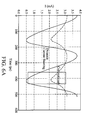
- Fig. 6A is a schematic diagram of current of a Gilbert cell mixer core in a conventional double balanced mixer and a dynamic current steering mixer according to an embodiment of the invention
- Figs. 6B and 6C are respectively schematic diagrams of current of the NMOS transistors in a Gilbert cell mixer core of a conventional double balanced mixer and a dynamic current steering mixer according to an embodiment of the invention
- Fig. 6D is a schematic diagram showing noise figure of a conventional double balanced mixer and a dynamic current steering mixer according to an embodiment of the invention
- Fig. 7A is a circuit diagram of a quadrature dynamic current steering mixer according to an embodiment of the invention.
- Fig. 7B is a schematic diagram showing waveforms of the local oscillator signals LOIP/LOIN and LOQP/LOQN and the control signals 2LOP and 2LON;
- Fig. 8A is a circuit diagram of a variant of the quadrature dynamic current steering mixer according to an embodiment of the invention.
- Fig. 8B is a circuit diagram of a variant of the quadrature dynamic current steering mixer in Fig. 8A .
- Fig. 3 is a circuit diagram of a dynamic current steering mixer according to an embodiment of the invention.
- the dynamic current steering mixer 300 comprises a Gilbert cell mixer core 310, a pair of load devices RL, a dynamic current steering cell 330, and a transconductor cell 350.
- the Gilbert cell mixer core 310 has first nodes 311 and 311' and second nodes 313 and 313' and comprises differential pairs of NMOS transistors T7-T8 and T9-T10 coupled therebetween.
- the Gilbert cell mixer core 310 receives a local oscillator signal LO+/LO-, and provides an intermediate frequency (IF) signal IF+/IF- at the first nodes 311 and 311'.
- LO+/LO- intermediate frequency
- the load devices RL are respectively coupled between the first nodes 311 and 311' of the Gilbert cell mixer core 310 and a supply voltage Vcc.
- the dynamic current steering cell 330 has third nodes 331 and 331' respectively coupled to the second nodes 313 and 313', and fourth nodes 333 and 333'.
- the dynamic current steering cell 330 comprises a first switch 335 and a second switch 335'.
- the first and second switches 335 and 335' alternately connect to the fourth nodes 333 and 333', the third node 331 and 331', and a fixed voltage Vdd according to a control signal 2fo, respectively.
- Frequency of the control signal is twice of that of the local oscillator signal LO+/LO-.
- the transconductor cell 350 comprises NMOS transistors T1 and T2 coupled between the fourth nodes 333 and 333'and a ground GND. Gates of the NMOS transistors T1 and T2 receive a radio frequency (RF) signal RF+/RF-.
- RF radio frequency
- Fig. 4A is a detailed circuit diagram of the dynamic current steering mixer in Fig. 3 .
- the dynamic current steering cell 330 comprises NMOS transistors T3, T4, T5 and T6.
- the NMOS transistors T3 and T6 are coupled between the third nodes 331 and 331' and the fourth nodes 333 and 333'.
- the NMOS transistors T4 and T5 are coupled between the fixed voltage Vdd and the fourth nodes 333 and 333'.
- Gates of the NMOS transistors T3 and T6 receive the control signal 2fo and those of the NMOS transistors T4 and T5 are connected to a reference voltage Vref.
- the fixed voltage Vdd is the same as the supply voltage Vcc.
- Fig. 4B is a schematic diagram showing waveforms of the local oscillator signal LO+/LO- and the control signal 2fo in Fig. 4A .
- voltage level of the control signal 2fo is lower than the reference voltage Vref, allowing the NMOS transistors T3 and T6 to be turned off.
- Current (both DC and AC) of the transconductor cell 350 is thus steered to the NMOS transistors T4 and T5. Since voltage level of the control signal 2fo exceeds the reference voltage Vref at non-zero-crossing points of the local oscillator signal LO+/LO-, the NMOS transistors T3 and T6 will be turned on.
- Fig. 4C shows another embodiment of the dynamic current steering mixer of the present invention.
- the main difference between the dynamic current steering mixer in Fig. 4A and in Fig.4C is that the Gilbert cell mixer core 310 and the load devices are folded down and coupled to the ground GND.
- the NMOS transistors T7, T8, T9 and T10 in the Gilbert cell mixer core 310 are replaced by PMOS transistors.
- Fig. 4D shows another embodiment of the dynamic current steering mixer of the present invention.
- the main difference between the dynamic current steering mixer in Fig. 4A and in Fig.4D is that the NMOS transistors T7, T8, T9 and T10 in the Gilbert cell mixer core 310 are replaced by bipolar junction transistors (BJTs).
- BJTs bipolar junction transistors
- the Gilbert cell mixer core 310 and the load devices in Fig. 4D can also be folded down and coupled to the ground GND.
- the dynamic current steering cell comprising the NMOS transistors T3, T4, T5, and T6 is an embodiment and the scope is not limited thereto. Bipolar junction transistors are also applicable to the dynamic current steering cell.
- Fig. 5A is a detailed circuit diagram of the dynamic current steering mixer in Fig. 3 .
- the dynamic current steering cell 330 comprises NMOS transistors T3, T4, T5 and T6.
- the NMOS transistors T3 and T6 are coupled between the third nodes 331 and 331' and the fourth nodes 333 and 333'.
- the NMOS transistors T4 and T5 are coupled between the fixed voltage Vdd and the fourth nodes 333 and 333'.
- Gates of the NMOS transistors T3 and T6 are connected to a reference voltage Vref and those of the NMOS transistors T4 and T5 receive the control signal 2fo.
- the fixed voltage Vdd is the same as the supply voltage Vcc.
- Fig. 5B is a schematic diagram showing waveforms of the local oscillator signal LO+/LO- and the control signal 2fo in Fig. 5A .
- voltage level of the control signal 2fo exceeds the reference voltage Vref, allowing the NMOS transistors T3 and T6to be turned off.
- Current (both DC and AC) of the transconductor cell 350 is thus steered to the NMOS transistors T4 and T5. Since voltage level of the control signal 2fo is lower than the reference voltage Vref at non-zero-crossing points of the local oscillator signal LO+/LO-, the NMOS transistors T3 and T6 are then turned on.
- Fig. 5C shows another embodiment of the dynamic current steering mixer of the present invention.
- the main difference between the dynamic current steering mixer in Fig. 5A and in Fig.5C is that the Gilbert cell mixer core 310 and the load devices are folded down and coupled to the ground GND.
- the NMOS transistors T7, T8, T9 and T10 in the Gilbert cell mixer core 310 are replaced by PMOS transistors.
- Fig. 5D shows another embodiment of the dynamic current steering mixer of the present invention.
- the main difference between the dynamic current steering mixer in Fig. 5A and in Fig.5D is that the NMOS transistors T7, T8, T9 and T10 in the Gilbert cell mixer core 310 are replaced by bipolar junction transistors (BJTs).
- BJTs bipolar junction transistors
- the Gilbert cell mixer core 310 and the load devices in Fig. 5D can also be folded down and coupled to the ground GND.
- the dynamic current steering cell comprising the NMOS transistors T3, T4, T5, and T6 is an embodiment and the scope is not limited thereto. Bipolar junction transistors are also applicable to the dynamic current steering cell.
- Fig. 6A is a schematic diagram of current of a Gilbert cell mixer core in a conventional double balanced mixer and a dynamic current steering mixer according to an embodiment of the invention.
- current of the Gilbert cell mixer core in a conventional double balanced mixer exceeds that of a dynamic current steering mixer according to an embodiment of the invention at zero-crossing points (represented by a dashed-line box).
- Figs. 6B and 6C are respectively schematic diagrams of current of the NMOS transistors in a Gilbert cell mixer core of a conventional double balanced mixer and a dynamic current steering mixer according to an embodiment of the invention.
- current of the NMOS transistors in a Gilbert cell mixer core of a conventional double balanced mixer is about 1mA.
- Fig. 6C current of the NMOS transistors in a Gilbert cell mixer core of a dynamic current steering mixer according to an embodiment of the invention is only about 0.3mA.
- Fig. 6D shows noise figure of a conventional double balanced mixer and a dynamic current steering mixer according to an embodiment of the invention.
- noise figure of a conventional double balanced mixer is 15.3dB at 10.4kHz and that of a dynamic current steering mixer according to an embodiment of the invention is only 12.3dB at 10.4kHz.
- Fig. 7A is a circuit diagram of a quadrature dynamic current steering mixer according to an embodiment of the invention.
- the quadrature dynamic current steering mixer 700 comprises an I-Quad mixer 710 and a Q-Quad mixer 760.
- the I-Quad mixer 710 and the Q-Quad mixer 760 are both dynamic current steering mixers as disclosed in Fig. 5A and connected in parallel between a supply voltage Vcc and a ground GND.
- the Gilbert mixer core 310 in the I-Quad mixer 710 receives a local oscillator signal LOIP/LOIN and that in the Q-Quad mixer 760 a local oscillator signal LOQP/LOQN.
- the dynamic current steering cell 330 in the I-Quad mixer 710 is controlled by a control signal 2LOP and that in the Q-Quad mixer 760 controlled by a control signal 2LON.
- the I-Quad mixer 710 generates an IF signal IFIP/IFIN and the Q-Quad mixer 760 an IF signal IFQP/IFQN. Since the I-Quad mixer 710 and the Q-Quad mixer 760 in the quadrature dynamic current steering mixer 700 are both dynamic current steering mixers, noise figure of the quadrature dynamic current steering mixer 700 according to an embodiment of the invention is also improved. It is noted that the disclosed variants of the dynamic current steering mixer in Fig. 4A and Fig. 5A can also be used in the quadrature dynamic current steering mixer.
- Fig. 7B is a schematic diagram showing waveforms of the local oscillator signals LOIP/LOIN and LOQP/LOQN and the control signals 2LOP and 2LON.
- Fig. 7B at a zero-crossing point t1 of the local oscillator signal LOIP/LOIN, since voltage level of the control signal 2LOP exceeds that of the reference voltage Vref, current Ia also exceeds current Ib. Meanwhile, voltage level of the reference voltage Vref also exceeds that of the control signal 2LON, and current Id thus exceeds current Ic.
- the currents Ia and Id consume most current at zero-crossing points of the local oscillator signal LOIP/LOIN and the currents Ib and Ic consume most current at zero-crossing points of the local oscillator signal LOQP/LOQN.
- current reuse is accomplished by combining current Ia with Id, and combining Ic with Ib.
- Fig. 8A is a circuit diagram of a variant of the quadrature dynamic current steering mixer according to an embodiment of the invention.
- the quadrature dynamic current steering mixer in Fig. 8A differs from that in Fig. 7A only in that drains of the NMOS transistors TI3, TI4, TI5, and TI6 in the I-Quad mixer 710 are respectively connected with drains of the NMOS transistors TQ4, TQ3, TQ6, and TQ5 in the Q-Quad mixer 760.
- Nodes A in Fig. 8A represent the drains of the NMOS transistors TI3 and TQ4 connected and nodes B in Fig. 8A represent the drains of the NMOS transistors TI4 and TQ3 are connected, and so forth. In such configuration, dynamic current steering and current combination are achieved and noise figure and current consumption are thus improved.
- Fig. 8B is a circuit diagram of a variant of the quadrature dynamic current steering mixer in Fig. 8A , differing only in that the I-Quad mixer 810 and the Q-Quad mixer 860 are both dynamic current steering mixer as disclosed in Fig. 4A .
Landscapes
- Engineering & Computer Science (AREA)
- Power Engineering (AREA)
- Superheterodyne Receivers (AREA)
- Amplifiers (AREA)
Abstract
Description
- The invention relates to a double-balanced mixer and, in particular, to a double-balance mixer with a dynamic current steering cell.
- Mixer circuits for high frequency applications constructed using metal oxide semiconductor (MOS) transistors are subject to a limited voltage supply (usually less than 2V) and high levels of flicker noise, having frequencies extending to several tens of MHz. Accordingly, the gain and output signal level required in such mixer circuits exceed those required in the equivalent bipolar circuits.
-
Fig. 1 is a circuit diagram illustrating a conventional double balanced mixer circuit. The double balanced mixer circuit inFIG. 1 includes differential pairs of MOSFETs (Q131-Q132 and Q133-Q134). The drains of the pairs of MOSFETs are connected to an output terminal (Output-I+ and Output-I-). The gates of the pairs of MOSFETs are connected to first input terminals (Input-II+ and Input-II-). The double balanced mixer circuit inFIG. 1 also includes active devices Q 13 5, Q 13 6, Q137 and Q 13 8. The sources of the MOSFET pair Q131-Q132 are connected to the drains of the active devices Q135 and Q136. The sources of the MOSFET pair Q133-Q134 are connected to the drains of the active devices Q137 and Q138. The gates of the active devices Q135, Q136, Q137 and Q138 are connected to the second input terminal (Input-I+ and Input-I-). The sources of the active devices Q135, Q136, Q137 and Q138 are connected to the ground through an impedance unit (Degeneration Impedance). -
Fig. 2 is a circuit diagram of a conventional quadrature mixer disclosed by Raja S Pullela et. al in ISSCC 2006. Theconventional quadrature mixer 200 comprises an I-Mixer Quad 210, a Q-Mixer Quad 220, a2x LO stage 230, and atransconductor stage 240. The I-Mixer Quad 210 inFIG. 2 includes differential pairs of MOSFETs (M9-M10 and M11-M12). The drains of the pairs of MOSFETs are connected to an output terminal (BBIp and BBIn). The gates of the pairs of MOSFETs are connected to first input terminals (LOIp and LOIn). The Q-Mixer Quad 220 inFIG. 2 includes differential pairs of MOSFETs (M13-M14 and M15-M16). The drains of the pairs of MOSFETs are connected to an output terminal (BBQp and BBQn). The gates of the pairs of MOSFETs are connected to first input terminals (LOQp and LOQn). The2x LO stage 230 comprises MOSFETs M5, M6, M7 and M8. Sources of the MOSFETs M9-M10 and M11-M12 are respectively connected to drains of the MOSFETs M5 and M7 and those of the MOSFETs M13-M14 and M15-M16 respectively connected to drains of the MOSFETs M6 and M8. Gates of the MOSFETs M5 and M7 are connected to an input terminal 2Lop and those of the MOSFETs M6 and M8 connected to an input terminal 2Lon. MOSFETs M1 and M3 are connected between the sources of the MOSFETs M5-M6 and a ground GND and MOSFETs M2 and M4 connected between the sources of the MOSFETs M7-M8 and the ground. Gates of the MOSFETs M1 and M3 are connected to an input terminal RF+ and those of the MOSFETs M2 and M4 connected to an input terminal RF-. - An embodiment of a dynamic current steering mixer comprises a Gilbert cell mixer core, a pair of load devices, a dynamic current steering cell, and a transconductor cell. The Gilbert cell mixer core has first and second nodes, receives a first differential input signal, and provides a differential output signal at the first nodes thereof. The load devices are respectively coupled between the first nodes of the Gilbert cell mixer core and a first fixed voltage. The dynamic current steering cell has third nodes coupled to the second nodes and fourth nodes. The transconductor cell is coupled between the fourth nodes and a second fixed voltage and receives a second differential input signal. The dynamic current steering cell alternately steers current of the transconductor cell to or away from the Gilbert cell mixer core.
- An embodiment of a quadrature dynamic current steering mixer comprises first and second dynamic current steering mixers connected in parallel between first and second fixed voltages. Each of the first and second dynamic current steering mixers comprises a Gilbert cell mixer core, a pair of load devices, a dynamic current steering cell, and a transconductor cell. The Gilbert cell mixer core has first and second nodes, receives a first differential input signal, and provides a differential output signal at the first nodes thereof. The load devices are respectively coupled between the first nodes of the Gilbert cell mixer core and the first fixed voltage. The dynamic current steering cell has third nodes coupled to the second nodes and fourth nodes. The transconductor cell is coupled between the fourth nodes and the second fixed voltage and receives a second differential input signal. The dynamic current steering cell alternately steers current of the transconductor cell to or away from the Gilbert cell mixer core. There is a phase difference of 90° between the first differential input signals of the first and second dynamic current steering mixers.
- A detailed description is given in the following embodiments with reference to the accompanying drawings.
- The invention can be more fully understood by reading the subsequent detailed description and examples with references made to the accompanying drawings, wherein:
-
Fig. 1 is a circuit diagram illustrating a conventional double balanced mixer circuit; -
Fig. 2 is a circuit diagram of a conventional quadrature mixer disclosed by Raja S Pullela et. al in ISSCC 2006; -
Fig. 3 is a circuit diagram of a dynamic current steering mixer according to an embodiment of the invention; -
Fig. 4A is a detailed circuit diagram of the dynamic current steering mixer inFig. 3 ; -
Fig. 4B is a schematic diagram showing waveforms of the local oscillator signal LO+/LO- and the control signal 2fo inFig. 4A ; -
Fig. 4C is a detailed diagram of a variant of the dynamic current steering mixer inFig. 4A ; -
Fig. 4D is a detailed diagram of another variant of the dynamic current steering mixer inFig. 4A ; -
Fig. 5A is a detailed circuit diagram of the dynamic current steering mixer inFig. 3 ; -
Fig. 5B is a schematic diagram showing waveforms of the local oscillator signal LO+/LO- and the control signal 2fo inFig. 5A ; -
Fig. 5C is a detailed diagram of a variant of the dynamic current steering mixer inFig. 5A ; -
Fig. 5D is a detailed diagram of another variant of the dynamic current steering mixer inFig. 5A ; -
Fig. 6A is a schematic diagram of current of a Gilbert cell mixer core in a conventional double balanced mixer and a dynamic current steering mixer according to an embodiment of the invention; -
Figs. 6B and6C are respectively schematic diagrams of current of the NMOS transistors in a Gilbert cell mixer core of a conventional double balanced mixer and a dynamic current steering mixer according to an embodiment of the invention; -
Fig. 6D is a schematic diagram showing noise figure of a conventional double balanced mixer and a dynamic current steering mixer according to an embodiment of the invention; -
Fig. 7A is a circuit diagram of a quadrature dynamic current steering mixer according to an embodiment of the invention; -
Fig. 7B is a schematic diagram showing waveforms of the local oscillator signals LOIP/LOIN and LOQP/LOQN and the control signals 2LOP and 2LON; -
Fig. 8A is a circuit diagram of a variant of the quadrature dynamic current steering mixer according to an embodiment of the invention; and -
Fig. 8B is a circuit diagram of a variant of the quadrature dynamic current steering mixer inFig. 8A . - The following description is of the best-contemplated mode of carrying out the invention. This description is made for the purpose of illustrating the general principles of the invention and should not be taken in a limiting sense. The scope of the invention is best determined by reference to the appended claims.
-
Fig. 3 is a circuit diagram of a dynamic current steering mixer according to an embodiment of the invention. The dynamiccurrent steering mixer 300 comprises a Gilbertcell mixer core 310, a pair of load devices RL, a dynamiccurrent steering cell 330, and atransconductor cell 350. The Gilbertcell mixer core 310 hasfirst nodes 311 and 311' andsecond nodes 313 and 313' and comprises differential pairs of NMOS transistors T7-T8 and T9-T10 coupled therebetween. The Gilbertcell mixer core 310 receives a local oscillator signal LO+/LO-, and provides an intermediate frequency (IF) signal IF+/IF- at thefirst nodes 311 and 311'. The load devices RL are respectively coupled between thefirst nodes 311 and 311' of the Gilbertcell mixer core 310 and a supply voltage Vcc. The dynamiccurrent steering cell 330 hasthird nodes 331 and 331' respectively coupled to thesecond nodes 313 and 313', andfourth nodes 333 and 333'. The dynamiccurrent steering cell 330 comprises afirst switch 335 and a second switch 335'. The first andsecond switches 335 and 335' alternately connect to thefourth nodes 333 and 333', thethird node 331 and 331', and a fixed voltage Vdd according to a control signal 2fo, respectively. Frequency of the control signal is twice of that of the local oscillator signal LO+/LO-. Thetransconductor cell 350 comprises NMOS transistors T1 and T2 coupled between thefourth nodes 333 and 333'and a ground GND. Gates of the NMOS transistors T1 and T2 receive a radio frequency (RF) signal RF+/RF-. -
Fig. 4A is a detailed circuit diagram of the dynamic current steering mixer inFig. 3 . InFig. 4A , the dynamiccurrent steering cell 330 comprises NMOS transistors T3, T4, T5 and T6. The NMOS transistors T3 and T6 are coupled between thethird nodes 331 and 331' and thefourth nodes 333 and 333'. The NMOS transistors T4 and T5 are coupled between the fixed voltage Vdd and thefourth nodes 333 and 333'. Gates of the NMOS transistors T3 and T6 receive the control signal 2fo and those of the NMOS transistors T4 and T5 are connected to a reference voltage Vref. Preferably, the fixed voltage Vdd is the same as the supply voltage Vcc.Fig. 4B is a schematic diagram showing waveforms of the local oscillator signal LO+/LO- and the control signal 2fo inFig. 4A . At zero-crossing points Toff of the local oscillator signal LO+/LO-, voltage level of the control signal 2fo is lower than the reference voltage Vref, allowing the NMOS transistors T3 and T6 to be turned off. Current (both DC and AC) of thetransconductor cell 350 is thus steered to the NMOS transistors T4 and T5. Since voltage level of the control signal 2fo exceeds the reference voltage Vref at non-zero-crossing points of the local oscillator signal LO+/LO-, the NMOS transistors T3 and T6 will be turned on. Current (both DC and AC) of thetransconductor cell 350 is thus steered to the NMOS transistors T3 and T6. It is well-known that flicker noise of the Gilbertcell mixer core 310 is proportional to a current injected therein at zero-crossing point. Therefore, steering current off the Gilbertcell mixer core 310 according to the dynamic current steering cell of the present invention can successfully suppress the flicker noise and would be insensitive to LO quality. -
Fig. 4C shows another embodiment of the dynamic current steering mixer of the present invention. The main difference between the dynamic current steering mixer inFig. 4A and inFig.4C is that the Gilbertcell mixer core 310 and the load devices are folded down and coupled to the ground GND. The NMOS transistors T7, T8, T9 and T10 in the Gilbertcell mixer core 310 are replaced by PMOS transistors. -
Fig. 4D shows another embodiment of the dynamic current steering mixer of the present invention. The main difference between the dynamic current steering mixer inFig. 4A and inFig.4D is that the NMOS transistors T7, T8, T9 and T10 in the Gilbertcell mixer core 310 are replaced by bipolar junction transistors (BJTs). It is noted that the Gilbertcell mixer core 310 and the load devices inFig. 4D can also be folded down and coupled to the ground GND. In addition, the dynamic current steering cell comprising the NMOS transistors T3, T4, T5, and T6 is an embodiment and the scope is not limited thereto. Bipolar junction transistors are also applicable to the dynamic current steering cell. -
Fig. 5A is a detailed circuit diagram of the dynamic current steering mixer inFig. 3 . InFig. 5A , the dynamiccurrent steering cell 330 comprises NMOS transistors T3, T4, T5 and T6. The NMOS transistors T3 and T6 are coupled between thethird nodes 331 and 331' and thefourth nodes 333 and 333'. The NMOS transistors T4 and T5 are coupled between the fixed voltage Vdd and thefourth nodes 333 and 333'. Gates of the NMOS transistors T3 and T6 are connected to a reference voltage Vref and those of the NMOS transistors T4 and T5 receive the control signal 2fo. Preferably, the fixed voltage Vdd is the same as the supply voltage Vcc.Fig. 5B is a schematic diagram showing waveforms of the local oscillator signal LO+/LO- and the control signal 2fo inFig. 5A . At zero-crossing points Toff of the local oscillator signal LO+/LO-, voltage level of the control signal 2fo exceeds the reference voltage Vref, allowing the NMOS transistors T3 and T6to be turned off. Current (both DC and AC) of thetransconductor cell 350 is thus steered to the NMOS transistors T4 and T5. Since voltage level of the control signal 2fo is lower than the reference voltage Vref at non-zero-crossing points of the local oscillator signal LO+/LO-, the NMOS transistors T3 and T6 are then turned on. Current (both DC and AC) of thetransconductor cell 350 is thus steered to the NMOS transistors T3 and T6. As a result, current of thetransconductor cell 350 is steered off the Gilbertcell mixer core 310 at zero-crossing points Toff of the local oscillator signal LO+/LO- and flicker noise thereof is thus suppressed. -
Fig. 5C shows another embodiment of the dynamic current steering mixer of the present invention. The main difference between the dynamic current steering mixer inFig. 5A and inFig.5C is that the Gilbertcell mixer core 310 and the load devices are folded down and coupled to the ground GND. The NMOS transistors T7, T8, T9 and T10 in the Gilbertcell mixer core 310 are replaced by PMOS transistors. -
Fig. 5D shows another embodiment of the dynamic current steering mixer of the present invention. The main difference between the dynamic current steering mixer inFig. 5A and inFig.5D is that the NMOS transistors T7, T8, T9 and T10 in the Gilbertcell mixer core 310 are replaced by bipolar junction transistors (BJTs). It is noted that the Gilbertcell mixer core 310 and the load devices inFig. 5D can also be folded down and coupled to the ground GND. In addition, the dynamic current steering cell comprising the NMOS transistors T3, T4, T5, and T6 is an embodiment and the scope is not limited thereto. Bipolar junction transistors are also applicable to the dynamic current steering cell. -
Fig. 6A is a schematic diagram of current of a Gilbert cell mixer core in a conventional double balanced mixer and a dynamic current steering mixer according to an embodiment of the invention. InFig. 6A , current of the Gilbert cell mixer core in a conventional double balanced mixer exceeds that of a dynamic current steering mixer according to an embodiment of the invention at zero-crossing points (represented by a dashed-line box).Figs. 6B and6C are respectively schematic diagrams of current of the NMOS transistors in a Gilbert cell mixer core of a conventional double balanced mixer and a dynamic current steering mixer according to an embodiment of the invention. InFig. 6B , current of the NMOS transistors in a Gilbert cell mixer core of a conventional double balanced mixer is about 1mA. InFig. 6C , current of the NMOS transistors in a Gilbert cell mixer core of a dynamic current steering mixer according to an embodiment of the invention is only about 0.3mA.Fig. 6D shows noise figure of a conventional double balanced mixer and a dynamic current steering mixer according to an embodiment of the invention. InFig.6D , noise figure of a conventional double balanced mixer is 15.3dB at 10.4kHz and that of a dynamic current steering mixer according to an embodiment of the invention is only 12.3dB at 10.4kHz. -
Fig. 7A is a circuit diagram of a quadrature dynamic current steering mixer according to an embodiment of the invention. InFig. 7A , the quadrature dynamic current steering mixer 700 comprises an I-Quad mixer 710 and a Q-Quad mixer 760. The I-Quad mixer 710 and the Q-Quad mixer 760 are both dynamic current steering mixers as disclosed inFig. 5A and connected in parallel between a supply voltage Vcc and a ground GND. TheGilbert mixer core 310 in the I-Quad mixer 710 receives a local oscillator signal LOIP/LOIN and that in the Q-Quad mixer 760 a local oscillator signal LOQP/LOQN. The dynamiccurrent steering cell 330 in the I-Quad mixer 710 is controlled by a control signal 2LOP and that in the Q-Quad mixer 760 controlled by a control signal 2LON. The I-Quad mixer 710 generates an IF signal IFIP/IFIN and the Q-Quad mixer 760 an IF signal IFQP/IFQN. Since the I-Quad mixer 710 and the Q-Quad mixer 760 in the quadrature dynamic current steering mixer 700 are both dynamic current steering mixers, noise figure of the quadrature dynamic current steering mixer 700 according to an embodiment of the invention is also improved. It is noted that the disclosed variants of the dynamic current steering mixer inFig. 4A andFig. 5A can also be used in the quadrature dynamic current steering mixer. -
Fig. 7B is a schematic diagram showing waveforms of the local oscillator signals LOIP/LOIN and LOQP/LOQN and the control signals 2LOP and 2LON. InFig. 7B , at a zero-crossing point t1 of the local oscillator signal LOIP/LOIN, since voltage level of the control signal 2LOP exceeds that of the reference voltage Vref, current Ia also exceeds current Ib. Meanwhile, voltage level of the reference voltage Vref also exceeds that of the control signal 2LON, and current Id thus exceeds current Ic. In other words, the currents Ia and Id consume most current at zero-crossing points of the local oscillator signal LOIP/LOIN and the currents Ib and Ic consume most current at zero-crossing points of the local oscillator signal LOQP/LOQN. As a result, current reuse is accomplished by combining current Ia with Id, and combining Ic with Ib. -
Fig. 8A is a circuit diagram of a variant of the quadrature dynamic current steering mixer according to an embodiment of the invention. The quadrature dynamic current steering mixer inFig. 8A differs from that inFig. 7A only in that drains of the NMOS transistors TI3, TI4, TI5, and TI6 in the I-Quad mixer 710 are respectively connected with drains of the NMOS transistors TQ4, TQ3, TQ6, and TQ5 in the Q-Quad mixer 760. Nodes A inFig. 8A represent the drains of the NMOS transistors TI3 and TQ4 connected and nodes B inFig. 8A represent the drains of the NMOS transistors TI4 and TQ3 are connected, and so forth. In such configuration, dynamic current steering and current combination are achieved and noise figure and current consumption are thus improved. -
Fig. 8B is a circuit diagram of a variant of the quadrature dynamic current steering mixer inFig. 8A , differing only in that the I-Quad mixer 810 and the Q-Quad mixer 860 are both dynamic current steering mixer as disclosed inFig. 4A . - While the invention has been described by way of example and in terms of preferred embodiment, it is to be understood that the invention is not limited thereto. Alternatively, it is intended to cover various modifications and similar arrangements as would be apparent to those skilled in the art. Therefore, the scope of the appended claims should be accorded the broadest interpretation so as to encompass all such modifications and similar arrangements.
Claims (25)
- A mixer, comprising:a Gilbert cell mixer core (310) having first and second nodes (311, 311'), receiving a first differential input signal, and providing a differential output signal at the first nodes thereof;a pair of load devices (RL) respectively coupled between the first nodes (311, 311') of the Gilbert cell mixer core and a first fixed voltage (Vcc);a dynamic current steering cell (330) having third nodes (331, 331') coupled to the second nodes (313, 313') and fourth nodes (333, 333'); anda transconductor cell (350) coupled between the fourth nodes (333, 333') and a second fixed voltage (GND) and receiving a second differential input signal;wherein the dynamic current steering cell alternately steers current of the transcondcutor cell (350) to or away from the Gilbert cell mixer core (310).
- The mixer as claimed in claim 1, wherein the dynamic current steering cell (330) comprises first MOS transistors coupled between the third and fourth nodes thereof and second MOS transistor coupled between the fourth nodes and a third fixed voltage, wherein gates of the first and second MOS transistors respectively receive one and the other of a reference voltage and a steering voltage.
- The mixer as claimed in claim 2, wherein frequency of the steering voltage is twice of that of the first differential input signal.
- The mixer as claimed in claim 2, wherein the first and third fixed voltages are the same.
- The mixer as claimed in any of the preceding claims, wherein the current of the transcondutor cell (350) is steered off the Gilbert cell mixer core (310) at zero-crossing points of the first differential input signal.
- The mixer as claimed in any of the preceding claims, wherein the first and second fixed voltages are respectively one and the other of a supply voltage and a ground.
- The mixer as claimed in any of the preceding claims, wherein the Gilbert cell mixer core (310) comprises differential pairs of MOS transistors (T7-T7, T9-T10).
- The mixer as claimed in any of claims 1 to 6, wherein the Gilbert cell mixer core comprises differential pairs of BJTs (bipolar junction transistors).
- The mixer as claimed in any of the preceding claims, wherein each of the load devices comprises a resistor.
- The mixer as claimed in any of the preceding claims, wherein the first and second fixed voltages are the same.
- A quadrature dynamic current steering mixer (700), comprising:first and second dynamic current steering mixers (710, 760) connected in parallel between first and second fixed voltages, each comprising:wherein first differential input signals of the first and second dynamic current steering mixers have a phase difference of 90°.a Gilbert cell mixer core having first and second nodes, receiving a first differential input signal, and providing a differential output signal at the first nodes thereof;a pair of load devices respectively coupled between the first nodes of the Gilbert cell mixer core and the first fixed voltage;a dynamic current steering cell having third nodes coupled to the second nodes and fourth nodes; anda transconductor cell coupled between the fourth nodes and the second fixed voltage and receiving a second differential input signal;wherein the dynamic current steering cell alternately steers current of the transconductor cell to or away from the Gilbert cell mixer core;
- The quadrature dynamic current steering mixer as claimed in claim 11, wherein each of the first and second dynamic current steering cells comprises first MOS transistors coupled between the third and fourth nodes thereof and second MOS transistor coupled between the fourth nodes and a third fixed voltage, wherein gates of the first and second MOS transistors respectively receive one and the other of a reference voltage and a steering voltage.
- The quadrature dynamic current steering mixer as claimed in claim 12, wherein frequency of the steering voltage is twice of that of the first differential input signal.
- The quadrature dynamic current steering mixer as claimed in claim 12, wherein the first and third fixed voltages are the same.
- The quadrature dynamic current steering mixer as claimed in any of claims 11 to 14, wherein the current of each transcondutor cell is steered off the Gilbert cell mixer core at zero-crossing points of the first differential input signal.
- The quadrature dynamic current steering mixer as claimed in any of claims 11 to 15, wherein the first and second fixed voltages are respectively one and the other of a supply voltage and a ground.
- The dynamic current steering mixer as claimed in any of claims 11 to 16, wherein the first and second fixed voltages are respectively one and the other of a supply voltage and a ground.
- The quadrature dynamic current steering mixer as claimed in any of claims 11 to 17, wherein each of the Gilbert cell mixer cores comprises differential pairs of MOS transistors.
- The quadrature dynamic current steering mixer as claimed in any of claims 11 to 17, wherein each of the Gilbert cell mixer cores comprises differential pairs of BJTs.
- The quadrature dynamic current steering mixer as claimed in any of claims 11 to 19, wherein each of the load devices comprises a resistor.
- The quadrature dynamic current steering mixer as claimed in any of claims 11 to 20, wherein each of the first and second dynamic current steering cells comprises first MOS transistors coupled between the third and fourth nodes thereof and second MOS transistor coupled between the fourth nodes and the third nodes of the other dynamic current steering cell, wherein gates of the first and second MOS transistors respectively receive one and the other of a reference voltage and a steering voltage.
- The quadrature dynamic current steering mixer as claimed in claim 21, wherein frequency of the steering voltage is twice of that of the first differential input signal.
- The quadrature dynamic current steering mixer as claimed in claim 21, wherein the first and third fixed voltages are the same.
- A mixer, comprising:a signal input;an RF transconductance circuit, having a pair of transistors, configured to convert an input differential signal received at the signal input into a differential current;a LO switching circuit, configured to switch the differential current between outputs of the mixer circuit at a rate determined by a differential LO signal; anda current steering circuit, coupled between the RF transconductance circuit and the LO switching circuit, having a first, a second, a third, and a fourth transistors, wherein the first and second transistors configured to receive a control signal with twice the frequency of the LO signal, and the third and fourth transistors coupled together to a common node with a reference voltage.
- A quadrature mixer, comprising:an I-quadrature mixer and a Q-quadrature mixer, having an identical signal input, each comprising:an RF transconductance circuit, having a pair of transistors, configured to convert an input differential signal received at the signal input into a differential current;a LO switching circuit, configured to switch the differential current between outputs of the mixer circuit at a rate determined by a differential LO signal; anda current steering circuit, coupled between the RF transconductance circuit and the LO switching circuit, having at least a first, a second, a third, and a fourth transistors, wherein the first and second transistors configured to receive a control signal with twice the frequency of the LO signal, and the third and fourth transistors coupled together to a common node with a reference voltage.
Applications Claiming Priority (1)
| Application Number | Priority Date | Filing Date | Title |
|---|---|---|---|
| US11/697,347 US7725092B2 (en) | 2007-04-06 | 2007-04-06 | Dynamic current steering mixer |
Publications (2)
| Publication Number | Publication Date |
|---|---|
| EP1978634A1 true EP1978634A1 (en) | 2008-10-08 |
| EP1978634B1 EP1978634B1 (en) | 2017-02-08 |
Family
ID=39666028
Family Applications (1)
| Application Number | Title | Priority Date | Filing Date |
|---|---|---|---|
| EP07106340.8A Not-in-force EP1978634B1 (en) | 2007-04-06 | 2007-04-17 | Dynamic current steering mixer |
Country Status (4)
| Country | Link |
|---|---|
| US (2) | US7725092B2 (en) |
| EP (1) | EP1978634B1 (en) |
| CN (1) | CN101282107B (en) |
| TW (1) | TWI343698B (en) |
Cited By (1)
| Publication number | Priority date | Publication date | Assignee | Title |
|---|---|---|---|---|
| WO2018175194A3 (en) * | 2017-03-20 | 2018-10-25 | Blue Danube Systems, Inc. | Precision high frequency phase adders |
Families Citing this family (13)
| Publication number | Priority date | Publication date | Assignee | Title |
|---|---|---|---|---|
| US8145155B2 (en) * | 2005-09-06 | 2012-03-27 | Mediatek, Inc. | Passive mixer and high Q RF filter using a passive mixer |
| US7881681B2 (en) * | 2006-08-28 | 2011-02-01 | Mediatek Inc. | Self-calibrating direct conversion transmitter with converting/steering device |
| US7725092B2 (en) * | 2007-04-06 | 2010-05-25 | Mediatek Inc. | Dynamic current steering mixer |
| JP4393544B2 (en) * | 2007-09-14 | 2010-01-06 | 株式会社東芝 | Mixer circuit and wireless communication apparatus using the same |
| US8072255B2 (en) * | 2008-01-07 | 2011-12-06 | Qualcomm Incorporated | Quadrature radio frequency mixer with low noise and low conversion loss |
| US20100056095A1 (en) * | 2008-09-02 | 2010-03-04 | Mediatek Inc. | Dynamic current injection mixer/modulator |
| CN102347730B (en) * | 2010-07-29 | 2014-06-18 | 晨星软件研发(深圳)有限公司 | Mixer for eliminating second-order inter-modulation distortion and relevant transconductor circuit of mixer |
| CN102522951B (en) * | 2011-12-20 | 2015-05-06 | 东南大学 | Integrated structure for low-noise amplifier and mixer by means of current multiplexing |
| US8964816B2 (en) * | 2013-02-12 | 2015-02-24 | Qualcomm Incorporated | Re-configurable receiver architecture for cable transmission |
| CN103401508B (en) * | 2013-08-19 | 2016-02-03 | 东南大学 | A kind of low noise amplifier and frequency mixer emerging system |
| DE112015007105T5 (en) * | 2015-12-11 | 2018-08-02 | Gm Global Technology Operations, Llc | ACTIVE SQUARE CIRCUITS FOR HIGH FREQUENCY APPLICATIONS |
| EP3619807B1 (en) | 2017-05-02 | 2024-07-31 | Jariet Technologies, Inc. | Double-balanced rf mixing digital-to-analog conversion |
| KR102153368B1 (en) * | 2018-11-26 | 2020-09-08 | 주식회사 파이칩스 | Mixer for rf receiver |
Citations (4)
| Publication number | Priority date | Publication date | Assignee | Title |
|---|---|---|---|---|
| FR2827097A1 (en) * | 2001-07-05 | 2003-01-10 | Zarlink Semiconductor Ltd | High frequency mixer with image rejection circuit having transconductance circuit two feed wires placed providing input signal and switching stage with central MOS mixer between transconductance circuit/load. |
| US20040038662A1 (en) * | 2002-08-20 | 2004-02-26 | Hooman Darabl | Reducing active mixer flicker noise |
| US20040063419A1 (en) * | 2002-09-30 | 2004-04-01 | Molnar Alyosha C. | Subharmonic mixer |
| US7046068B2 (en) * | 2004-04-27 | 2006-05-16 | Broadcom Corporation | CMOS-based receiver for communications applications |
Family Cites Families (19)
| Publication number | Priority date | Publication date | Assignee | Title |
|---|---|---|---|---|
| JPH07503586A (en) * | 1992-02-03 | 1995-04-13 | モトローラ・インコーポレイテッド | Balanced mixer circuit with improved linearity |
| US6040731A (en) * | 1997-05-01 | 2000-03-21 | Raytheon Company | Differential pair gain control stage |
| US5859559A (en) * | 1997-07-31 | 1999-01-12 | Raytheon Company | Mixer structures with enhanced conversion gain and reduced spurious signals |
| US6438365B1 (en) * | 1998-06-02 | 2002-08-20 | Philsar Semiconductor Inc. | Balanced mixer with feedback pre-amplifier |
| US6591093B1 (en) * | 1999-10-25 | 2003-07-08 | Motorola, Inc. | Circuit and method for frequency translation |
| US6510314B1 (en) * | 2000-09-08 | 2003-01-21 | Visteon Global Technologies, Inc. | Mixer circuit with output stage for implementation on integrated circuit |
| US6370372B1 (en) * | 2000-09-25 | 2002-04-09 | Conexant Systems, Inc. | Subharmonic mixer circuit and method |
| EP1346467B1 (en) * | 2000-11-29 | 2010-02-10 | Broadcom Corporation | Integrated direct conversion satellite tuner |
| AU2002324560A1 (en) * | 2001-08-01 | 2003-02-17 | Santel Networks, Inc. | Method and apparatus for analog multipliers employed in analog filtering system |
| JP3828793B2 (en) * | 2001-12-04 | 2006-10-04 | Necエレクトロニクス株式会社 | Quadrature mixer circuit |
| US6639447B2 (en) * | 2002-03-08 | 2003-10-28 | Sirific Wireless Corporation | High linearity Gilbert I Q dual mixer |
| FR2844066A1 (en) * | 2002-08-28 | 2004-03-05 | St Microelectronics Sa | Control of quiescent currents in a direct frequency converter used in mobile telephones, uses closed loop regulation of common-mode quiescent current so it tracks reference current |
| US7177620B1 (en) * | 2003-01-29 | 2007-02-13 | Marvell International Ltd. | Mixer constant linear range biasing apparatus and method |
| US20050124311A1 (en) * | 2003-12-03 | 2005-06-09 | Farsheed Mahmoudi | Low-voltage low-power high-linearity active CMOS mixer |
| US7546109B2 (en) * | 2005-06-30 | 2009-06-09 | International Business Machines Corporation | Gilbert mixers with improved isolation and methods therefor |
| US7398073B2 (en) * | 2005-09-06 | 2008-07-08 | Skyworks Solutions, Inc. | Low noise mixer |
| US7577418B2 (en) * | 2006-07-18 | 2009-08-18 | United Microelectronics Corp. | Sub-harmonic mixer and down converter with the same |
| US7769361B2 (en) * | 2006-07-19 | 2010-08-03 | Qualcomm Incorporated | Systems, methods, and apparatus for frequency conversion |
| US7725092B2 (en) * | 2007-04-06 | 2010-05-25 | Mediatek Inc. | Dynamic current steering mixer |
-
2007
- 2007-04-06 US US11/697,347 patent/US7725092B2/en active Active
- 2007-04-17 EP EP07106340.8A patent/EP1978634B1/en not_active Not-in-force
-
2008
- 2008-04-03 CN CN2008100916012A patent/CN101282107B/en not_active Expired - Fee Related
- 2008-04-03 TW TW097112137A patent/TWI343698B/en not_active IP Right Cessation
-
2010
- 2010-04-12 US US12/758,149 patent/US8064868B2/en active Active
Patent Citations (4)
| Publication number | Priority date | Publication date | Assignee | Title |
|---|---|---|---|---|
| FR2827097A1 (en) * | 2001-07-05 | 2003-01-10 | Zarlink Semiconductor Ltd | High frequency mixer with image rejection circuit having transconductance circuit two feed wires placed providing input signal and switching stage with central MOS mixer between transconductance circuit/load. |
| US20040038662A1 (en) * | 2002-08-20 | 2004-02-26 | Hooman Darabl | Reducing active mixer flicker noise |
| US20040063419A1 (en) * | 2002-09-30 | 2004-04-01 | Molnar Alyosha C. | Subharmonic mixer |
| US7046068B2 (en) * | 2004-04-27 | 2006-05-16 | Broadcom Corporation | CMOS-based receiver for communications applications |
Non-Patent Citations (1)
| Title |
|---|
| HOOMAN DARABI ET AL: "Noise in RF-CMOS Mixers: A SimplePhysical Model", IEEE JOURNAL OF SOLID-STATE CIRCUITS, IEEE SERVICE CENTER, PISCATAWAY, NJ, US, vol. 35, no. 1, 1 January 2000 (2000-01-01), XP011061161, ISSN: 0018-9200 * |
Cited By (4)
| Publication number | Priority date | Publication date | Assignee | Title |
|---|---|---|---|---|
| WO2018175194A3 (en) * | 2017-03-20 | 2018-10-25 | Blue Danube Systems, Inc. | Precision high frequency phase adders |
| US10693417B2 (en) | 2017-03-20 | 2020-06-23 | Blue Danube Systems, Inc. | Precision high frequency phase adders |
| US10917048B2 (en) | 2017-03-20 | 2021-02-09 | Blue Danube Systems, Inc. | Precision high frequency phase adders |
| US11962273B2 (en) | 2017-03-20 | 2024-04-16 | Nec Advanced Networks, Inc. | Precision high frequency phase adders |
Also Published As
| Publication number | Publication date |
|---|---|
| EP1978634B1 (en) | 2017-02-08 |
| TWI343698B (en) | 2011-06-11 |
| TW200841585A (en) | 2008-10-16 |
| US20080248775A1 (en) | 2008-10-09 |
| US7725092B2 (en) | 2010-05-25 |
| CN101282107B (en) | 2012-09-05 |
| CN101282107A (en) | 2008-10-08 |
| US8064868B2 (en) | 2011-11-22 |
| US20100195767A1 (en) | 2010-08-05 |
Similar Documents
| Publication | Publication Date | Title |
|---|---|---|
| US7725092B2 (en) | Dynamic current steering mixer | |
| US7271640B2 (en) | Mixer circuit with bypass and mixing modes having constant even order generation and method of operation | |
| US5767726A (en) | Four terminal RF mixer device | |
| US5768700A (en) | High conversion gain CMOS mixer | |
| EP1636901B1 (en) | Mixer circuit, receiver comprising a mixer circuit, wireless communication comprising a receiver, method for generating an output signal by mixing an input signal with an oscillator signal | |
| TWI424681B (en) | Mixer circuit and method for reducing flicker noise thereof | |
| US8538366B2 (en) | Rotating harmonic rejection mixer | |
| TW200816620A (en) | System, methods, and apparatus for frequency conversion | |
| US20040041616A1 (en) | Apparatus and method for improved chopping mixer | |
| US20130027017A1 (en) | Voltage to current converting circuit | |
| US20100056095A1 (en) | Dynamic current injection mixer/modulator | |
| Harvey et al. | Analysis and design of an integrated quadrature mixer with improved noise, gain and image rejection | |
| US20080068052A1 (en) | Frequency doubler using dual gilbert mixers | |
| US7012457B2 (en) | Mixer circuit offset compensation | |
| US7498861B2 (en) | Mixer | |
| US10666239B2 (en) | Balanced frequency doubler | |
| KR100721171B1 (en) | Frequency conversion circuit | |
| JP2006074380A (en) | Frequency mixer | |
| CN110120785B (en) | A low-power mixer | |
| JP4495532B2 (en) | Frequency converter and RF receiver using the same | |
| US20090243700A1 (en) | Mixer circuit for frequency mixing of differential signals | |
| KR101390037B1 (en) | Frequency mixer | |
| Kawokgy | Low-Power Low-Voltage CMOS RF Mixers | |
| Klumperink et al. | Switched Transconductor Mixer Compatible with Future CMOS | |
| JP2004187101A (en) | Mixer circuit |
Legal Events
| Date | Code | Title | Description |
|---|---|---|---|
| PUAI | Public reference made under article 153(3) epc to a published international application that has entered the european phase |
Free format text: ORIGINAL CODE: 0009012 |
|
| AK | Designated contracting states |
Kind code of ref document: A1 Designated state(s): AT BE BG CH CY CZ DE DK EE ES FI FR GB GR HU IE IS IT LI LT LU LV MC MT NL PL PT RO SE SI SK TR |
|
| AX | Request for extension of the european patent |
Extension state: AL BA HR MK RS |
|
| 17P | Request for examination filed |
Effective date: 20090310 |
|
| AKX | Designation fees paid |
Designated state(s): DE FR GB NL |
|
| 17Q | First examination report despatched |
Effective date: 20150805 |
|
| GRAP | Despatch of communication of intention to grant a patent |
Free format text: ORIGINAL CODE: EPIDOSNIGR1 |
|
| INTG | Intention to grant announced |
Effective date: 20160830 |
|
| STAA | Information on the status of an ep patent application or granted ep patent |
Free format text: STATUS: GRANT OF PATENT IS INTENDED |
|
| GRAS | Grant fee paid |
Free format text: ORIGINAL CODE: EPIDOSNIGR3 |
|
| GRAA | (expected) grant |
Free format text: ORIGINAL CODE: 0009210 |
|
| STAA | Information on the status of an ep patent application or granted ep patent |
Free format text: STATUS: THE PATENT HAS BEEN GRANTED |
|
| AK | Designated contracting states |
Kind code of ref document: B1 Designated state(s): DE FR GB NL |
|
| REG | Reference to a national code |
Ref country code: GB Ref legal event code: FG4D |
|
| REG | Reference to a national code |
Ref country code: DE Ref legal event code: R096 Ref document number: 602007049752 Country of ref document: DE |
|
| REG | Reference to a national code |
Ref country code: FR Ref legal event code: PLFP Year of fee payment: 11 |
|
| REG | Reference to a national code |
Ref country code: NL Ref legal event code: MP Effective date: 20170208 |
|
| PG25 | Lapsed in a contracting state [announced via postgrant information from national office to epo] |
Ref country code: NL Free format text: LAPSE BECAUSE OF FAILURE TO SUBMIT A TRANSLATION OF THE DESCRIPTION OR TO PAY THE FEE WITHIN THE PRESCRIBED TIME-LIMIT Effective date: 20170208 |
|
| REG | Reference to a national code |
Ref country code: DE Ref legal event code: R097 Ref document number: 602007049752 Country of ref document: DE |
|
| PLBE | No opposition filed within time limit |
Free format text: ORIGINAL CODE: 0009261 |
|
| STAA | Information on the status of an ep patent application or granted ep patent |
Free format text: STATUS: NO OPPOSITION FILED WITHIN TIME LIMIT |
|
| 26N | No opposition filed |
Effective date: 20171109 |
|
| REG | Reference to a national code |
Ref country code: FR Ref legal event code: PLFP Year of fee payment: 12 |
|
| P01 | Opt-out of the competence of the unified patent court (upc) registered |
Effective date: 20230607 |
|
| PGFP | Annual fee paid to national office [announced via postgrant information from national office to epo] |
Ref country code: FR Payment date: 20230425 Year of fee payment: 17 Ref country code: DE Payment date: 20230427 Year of fee payment: 17 |
|
| PGFP | Annual fee paid to national office [announced via postgrant information from national office to epo] |
Ref country code: GB Payment date: 20230427 Year of fee payment: 17 |
|
| REG | Reference to a national code |
Ref country code: DE Ref legal event code: R119 Ref document number: 602007049752 Country of ref document: DE |
|
| GBPC | Gb: european patent ceased through non-payment of renewal fee |
Effective date: 20240417 |
|
| PG25 | Lapsed in a contracting state [announced via postgrant information from national office to epo] |
Ref country code: DE Free format text: LAPSE BECAUSE OF NON-PAYMENT OF DUE FEES Effective date: 20241105 |
|
| PG25 | Lapsed in a contracting state [announced via postgrant information from national office to epo] |
Ref country code: GB Free format text: LAPSE BECAUSE OF NON-PAYMENT OF DUE FEES Effective date: 20240417 |
|
| PG25 | Lapsed in a contracting state [announced via postgrant information from national office to epo] |
Ref country code: FR Free format text: LAPSE BECAUSE OF NON-PAYMENT OF DUE FEES Effective date: 20240430 |
|
| PG25 | Lapsed in a contracting state [announced via postgrant information from national office to epo] |
Ref country code: GB Free format text: LAPSE BECAUSE OF NON-PAYMENT OF DUE FEES Effective date: 20240417 Ref country code: FR Free format text: LAPSE BECAUSE OF NON-PAYMENT OF DUE FEES Effective date: 20240430 Ref country code: DE Free format text: LAPSE BECAUSE OF NON-PAYMENT OF DUE FEES Effective date: 20241105 |