EP1978318A2 - Apparatus including freezing unit and projector including freezing unit - Google Patents
Apparatus including freezing unit and projector including freezing unit Download PDFInfo
- Publication number
- EP1978318A2 EP1978318A2 EP08005915A EP08005915A EP1978318A2 EP 1978318 A2 EP1978318 A2 EP 1978318A2 EP 08005915 A EP08005915 A EP 08005915A EP 08005915 A EP08005915 A EP 08005915A EP 1978318 A2 EP1978318 A2 EP 1978318A2
- Authority
- EP
- European Patent Office
- Prior art keywords
- evaporator
- freezing unit
- main body
- liquid crystal
- radiator
- Prior art date
- Legal status (The legal status is an assumption and is not a legal conclusion. Google has not performed a legal analysis and makes no representation as to the accuracy of the status listed.)
- Withdrawn
Links
- 238000007710 freezing Methods 0.000 title claims abstract description 59
- 230000008014 freezing Effects 0.000 title claims abstract description 59
- 239000003507 refrigerant Substances 0.000 claims abstract description 69
- 239000007788 liquid Substances 0.000 claims abstract description 19
- 230000008859 change Effects 0.000 claims abstract description 11
- 230000003287 optical effect Effects 0.000 claims description 40
- 238000000034 method Methods 0.000 claims description 4
- 230000008569 process Effects 0.000 claims description 4
- 239000004973 liquid crystal related substance Substances 0.000 abstract description 59
- 238000007599 discharging Methods 0.000 abstract description 3
- 230000036544 posture Effects 0.000 description 29
- 238000004891 communication Methods 0.000 description 14
- XLYOFNOQVPJJNP-UHFFFAOYSA-N water Substances O XLYOFNOQVPJJNP-UHFFFAOYSA-N 0.000 description 9
- 230000004907 flux Effects 0.000 description 7
- 238000010586 diagram Methods 0.000 description 6
- 239000011810 insulating material Substances 0.000 description 6
- 239000000463 material Substances 0.000 description 6
- 238000001816 cooling Methods 0.000 description 5
- 238000005286 illumination Methods 0.000 description 5
- 230000006835 compression Effects 0.000 description 4
- 238000007906 compression Methods 0.000 description 4
- 229910052751 metal Inorganic materials 0.000 description 4
- 239000002184 metal Substances 0.000 description 4
- 230000010287 polarization Effects 0.000 description 4
- 238000000926 separation method Methods 0.000 description 4
- 239000003086 colorant Substances 0.000 description 3
- 239000000835 fiber Substances 0.000 description 3
- 239000003921 oil Substances 0.000 description 3
- 230000000694 effects Effects 0.000 description 2
- 230000005484 gravity Effects 0.000 description 2
- 238000009434 installation Methods 0.000 description 2
- 229920005989 resin Polymers 0.000 description 2
- 239000011347 resin Substances 0.000 description 2
- YCKRFDGAMUMZLT-UHFFFAOYSA-N Fluorine atom Chemical compound [F] YCKRFDGAMUMZLT-UHFFFAOYSA-N 0.000 description 1
- FYYHWMGAXLPEAU-UHFFFAOYSA-N Magnesium Chemical compound [Mg] FYYHWMGAXLPEAU-UHFFFAOYSA-N 0.000 description 1
- VYPSYNLAJGMNEJ-UHFFFAOYSA-N Silicium dioxide Chemical compound O=[Si]=O VYPSYNLAJGMNEJ-UHFFFAOYSA-N 0.000 description 1
- XUIMIQQOPSSXEZ-UHFFFAOYSA-N Silicon Chemical compound [Si] XUIMIQQOPSSXEZ-UHFFFAOYSA-N 0.000 description 1
- PPBRXRYQALVLMV-UHFFFAOYSA-N Styrene Chemical compound C=CC1=CC=CC=C1 PPBRXRYQALVLMV-UHFFFAOYSA-N 0.000 description 1
- 238000007664 blowing Methods 0.000 description 1
- 238000010276 construction Methods 0.000 description 1
- 239000007799 cork Substances 0.000 description 1
- 238000001704 evaporation Methods 0.000 description 1
- 230000008020 evaporation Effects 0.000 description 1
- 239000002657 fibrous material Substances 0.000 description 1
- 229910052731 fluorine Inorganic materials 0.000 description 1
- 239000011737 fluorine Substances 0.000 description 1
- 239000006260 foam Substances 0.000 description 1
- 239000011521 glass Substances 0.000 description 1
- 239000011491 glass wool Substances 0.000 description 1
- 239000002241 glass-ceramic Substances 0.000 description 1
- 230000006872 improvement Effects 0.000 description 1
- 230000001050 lubricating effect Effects 0.000 description 1
- 229910052749 magnesium Inorganic materials 0.000 description 1
- 239000011777 magnesium Substances 0.000 description 1
- 238000004519 manufacturing process Methods 0.000 description 1
- 230000007246 mechanism Effects 0.000 description 1
- QSHDDOUJBYECFT-UHFFFAOYSA-N mercury Chemical compound [Hg] QSHDDOUJBYECFT-UHFFFAOYSA-N 0.000 description 1
- 229910052753 mercury Inorganic materials 0.000 description 1
- 239000011490 mineral wool Substances 0.000 description 1
- 239000012466 permeate Substances 0.000 description 1
- 239000005011 phenolic resin Substances 0.000 description 1
- 239000004033 plastic Substances 0.000 description 1
- 229920003023 plastic Polymers 0.000 description 1
- 229920005668 polycarbonate resin Polymers 0.000 description 1
- 239000004431 polycarbonate resin Substances 0.000 description 1
- 229920005990 polystyrene resin Polymers 0.000 description 1
- 229910052710 silicon Inorganic materials 0.000 description 1
- 239000010703 silicon Substances 0.000 description 1
- 229920002554 vinyl polymer Polymers 0.000 description 1
Images




Classifications
-
- F—MECHANICAL ENGINEERING; LIGHTING; HEATING; WEAPONS; BLASTING
- F25—REFRIGERATION OR COOLING; COMBINED HEATING AND REFRIGERATION SYSTEMS; HEAT PUMP SYSTEMS; MANUFACTURE OR STORAGE OF ICE; LIQUEFACTION SOLIDIFICATION OF GASES
- F25D—REFRIGERATORS; COLD ROOMS; ICE-BOXES; COOLING OR FREEZING APPARATUS NOT OTHERWISE PROVIDED FOR
- F25D21/00—Defrosting; Preventing frosting; Removing condensed or defrost water
- F25D21/14—Collecting or removing condensed and defrost water; Drip trays
-
- G—PHYSICS
- G03—PHOTOGRAPHY; CINEMATOGRAPHY; ANALOGOUS TECHNIQUES USING WAVES OTHER THAN OPTICAL WAVES; ELECTROGRAPHY; HOLOGRAPHY
- G03B—APPARATUS OR ARRANGEMENTS FOR TAKING PHOTOGRAPHS OR FOR PROJECTING OR VIEWING THEM; APPARATUS OR ARRANGEMENTS EMPLOYING ANALOGOUS TECHNIQUES USING WAVES OTHER THAN OPTICAL WAVES; ACCESSORIES THEREFOR
- G03B21/00—Projectors or projection-type viewers; Accessories therefor
- G03B21/14—Details
- G03B21/16—Cooling; Preventing overheating
Definitions
- the present invention relates to an apparatus in which a main body includes a freezing unit having a refrigerant circuit constituted of a compressor, a radiator, a pressure reducing unit, an evaporator and the like, and it also relates to a projector including the freezing unit.
- a freezing unit having a refrigerant circuit constituted of a compressor, a radiator, a pressure reducing unit, an evaporator and the like is mounted on various apparatus such as a refrigerator, a freezer and an air conditioner.
- a refrigerant is sucked into a compression space and compressed therein to form a high-temperature high-pressure refrigerant gas which flows into the radiator.
- the refrigerant which has flowed into the radiator performs heat exchange between the refrigerant and surrounding air to radiate heat.
- a pressure of the refrigerant is reduced in the pressure reducing unit, and the refrigerant reaches the evaporator.
- the refrigerant absorbs heat from the surrounding air to evaporate in the evaporator, and is then sucked into the compressor again, and this cycle is repeated.
- the heat exchange between the evaporator and the refrigerant is performed, whereby a water content included in the air is condensed on the surface of the evaporator, and drops down as water droplets.
- a tray is installed in a lower part of the evaporator so that drainage (condensed water) from the evaporator can be received in this tray. Then, the drainage which has dropped down to the tray is then discharged from the freezing unit via a pipe connected to a bottom part of the tray (e.g., Japanese Patent Application Laid-Open No. 2001-99558 ).
- the applicant has previously developed a projector including this freezing unit mounted thereon so that an optical element of the projector is cooled in the cold air through the evaporator.
- the optical element of the projector is cooled in the freezing unit in this manner, whereby a temperature of the optical element can be held at a suitable temperature.
- various effects such as reducing of amount of air flows, improvement of an energy efficiency and reducing of an installation space can be obtained.
- such a projector is provided so that the main body is rotatable around a burner axis (an optical axis) of a light source lamp, and hence the freezing unit needs to be provided in accordance with this constitution.
- the drainage from the evaporator drops down to any place owing to the rotation of the projector. Therefore, when the tray is only installed in the lower part of the evaporator as in the conventional example, with all prospective postures of the main body, the drainage from the evaporator cannot be received and discharged from the projector.
- the present invention has been developed in order to solve a conventional technical problem, and an object thereof is to provide an apparatus including a freezing unit capable of securely discharging drainage from an evaporator regardless of a posture change of a main body, and a projector including the freezing unit.
- An apparatus including a freezing unit is an apparatus in which a main body is provided with the freezing unit having a refrigerant circuit constituted of at least a compressor, a radiator, a pressure reducing unit and an evaporator, characterized by comprising: a liquid receiving portion constituted in the whole region under the evaporator in a prospective posture change of the main body; and a discharge member which discharges drainage received in this liquid receiving portion by use of a capillary force or a permeation force.
- An apparatus including the freezing unit according to a second aspect of the invention is characterized in that in the first aspect of the invention, the discharge member discharges, to the radiator, the drainage received in the liquid receiving portion.
- a projector including a freezing unit which is the apparatus according to the above inventions, characterized by comprising a main body including a light source, an optical element which processes light emitted from this light source in accordance with image information, a projection lens which projects a projected image of the processed light onto a screen, and a duct in which an evaporator is incorporated and which supplies, to the optical element, air subjected to heat exchange between the air and the evaporator, wherein the liquid receiving portion is constituted in an inner surface of the duct.
- the apparatus in which the main body is provided with the freezing unit having the refrigerant circuit constituted of at least the compressor, the radiator, the pressure reducing unit and the evaporator comprises the liquid receiving portion constituted in the whole region under the evaporator in the prospective posture change of the main body, and the discharge member which discharges the drainage received in this liquid receiving portion by use of the capillary force or the permeation force. Therefore, even when the posture of the main body changes, the drainage from the evaporator can be received by the liquid receiving portion, and can be described from the apparatus by the discharge member.
- the discharge member discharges, to the radiator, the drainage received in the liquid receiving portion, so that the drainage can be evaporated by radiant heat of the radiator.
- the projector is the apparatus according to the first or second aspect of the invention
- the main body of the projector includes the light source, the optical element which processes the light emitted from this light source in accordance with the image information, the projection lens which projects the projection image of the processed light onto the screen, and the duct in which the evaporator is incorporated and which supplies, to the optical element, the air subjected to the heat exchange between the air and the evaporator, and the liquid receiving portion is constituted in the duct inner surface.
- FIG. 1 is a schematic perspective view showing a projector as one embodiment of an apparatus including a freezing unit according to the present invention.
- the projector according to the present embodiment is a liquid crystal display projector P constituted by providing, in a main body 1, a light source 2, an optical path changing member 3, a uniform illumination optical system (not shown), a color separation optical system (not shown), an optical element 5, a projection lens 9 and a freezing unit 10 of the optical element 5.
- the main body 1 is a flat housing constituted of a material having an excellent heat release property, for example, magnesium. It is to be noted that for the sake of description of each unit provided in the main body 1, the main body 1 is shown in a flat section in which an upper part of the main body is cut.
- the light source 2 includes a lamp 20 such as an extra-high pressure mercury lamp, and a reflector 21 for emitting forwards light (divergent light) diverging from the lamp.
- a lamp 20 such as an extra-high pressure mercury lamp
- a reflector 21 for emitting forwards light (divergent light) diverging from the lamp.
- a plurality of (four) lamps 20 are provided with the reflectors 21, respectively, and the light source is received in lamp boxes 22 provided in the main body 1.
- the uniform illumination optical system converts the light emitted from the light source 2 into a parallel luminous flux having a uniform luminance distribution, and includes an integrator lens, a condenser lens and the like.
- the color separation optical system separates the parallel luminous flux from the uniform illumination optical system into light of colors R, G and B, and includes a dichroic mirror (not shown) and a mirror 4 for reflection (not shown in FIG. 1 , and shown in FIG. 4 as described later) which separates the parallel luminous flux from the uniform illumination optical system into the respective colors and the like.
- the optical element 5 includes three liquid crystal display panels (LCD panels) 6, incident-side sheet polarizers 8A each disposed with a space from each liquid crystal panel 6 on an incidence side of the panel, outgoing-side sheet polarizers 8B (shown in FIGS. 4 and 5 as described later) each disposed with a space from each liquid crystal panel 6 on an emission side, a cross dichroic prism 25 and the like.
- the liquid crystal display panels 6 process (modulate) light separated by the color separation optical system and guided to the liquid crystal display panels 6 in accordance with image information.
- the cross dichroic prism 25 synthesizes each color light to form a projected light image.
- This cross dichroic prism 25 includes a reflective surface including X-like dielectric multilayer films, and the light from each liquid crystal panel 6 is formed into a single luminous flux via the reflective surface. It is to be noted that the projection lens 9 enlarges and projects the projected light image from the cross dichroic prism 25 onto the screen, and is detachably attached to a hole (not shown) formed in a wall surface of the main body 1. Further in FIG.
- reference numeral 27 is a box member which covers an optical path for guiding the light emitted from the light source 2 to the liquid crystal display panels 6, the incident-side sheet polarizers 8A, 8B and the like, 1T is a leg portion provided on a bottom part of the main body 1, and 18M is a motor of a fan 18F described later. That is, a path (an optical path) through which the light passes from the light source 2 to the incident-side sheet polarizers 8A on the incidence side of the liquid crystal display panels 6 is formed in the box member 27.
- the light emitted from the light source 2 is converted into the parallel luminous fluxes having a uniform luminance distribution via the uniform illumination optical system, separated into the light of the colors R, G and B in the color separation optical system, and guided into the liquid crystal display panels 6 which function as corresponding light bulbs via the incidence-side incident-side sheet polarizers 8A.
- the luminous fluxes guided into the liquid crystal display panels 6 are modulated in accordance with the image information in the panels, converted into a projected image of the single luminous flux by the cross dichroic prism 25 through the emission-side outgoing-side sheet polarizers 8B, and enlarged and projected on the screen by the projection lens 9.
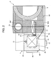
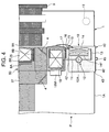
- FIGS. 2 to 4 are diagrams showing arrangements of the freezing unit 10 of the present invention as viewed from a front surface (a projection lens 9 side), a side surface and a plane.
- the liquid crystal display projector P of the present invention includes the freezing unit 10 in the main body 1.
- This freezing unit 10 cools the optical element 5 including the liquid crystal display panels 6, the incident-side sheet polarizers 8A, 8B, the cross dichroic cross dichroic prism 25 and the like, and is constituted of a compressor 12, a radiator 14, a capillary tube 16 (a pressure reducing unit of the present invention) and an evaporator 18 as shown in FIGS. 2 to 4 .
- a refrigerant discharge tube 13 of the compressor 12 is connected to an inlet of the radiator 14, and an outlet of the radiator 14 is connected to a refrigerant pipe 15 extending to the capillary tube 16.
- An outlet of the capillary tube 16 is connected to an inlet of the evaporator 18 via a refrigerant pipe 17 (an inlet pipe of the evaporator 18), and an outlet of the evaporator 18 is connected to a refrigerant suction tube 11 (an outlet pipe of the evaporator 18) of the compressor 12 to constitute an annular refrigerant circuit.
- the compressor 12 of the present embodiment is constituted by disposing, in a sealed container 12A having a vertically long cylindrical shape, a compression element and an electromotive element (a driving element) for driving this compression element.
- the radiator 14 for use in the embodiment is a heat exchanger of an air cooling type, and hence a fan 14F as blowing means is installed in the vicinity of (on the side of) the radiator 14.
- the capillary tube 16 is used as a unit to reduce a pressure of the refrigerant, but the pressure reducing unit is not limited to the capillary tube, and any type of unit, for example, an expansion valve may be used as long as the pressure of the refrigerant can be reduced to a predetermined pressure.
- the freezing unit 10 is constituted so that a basic posture thereof can be maintained in accordance with a posture change of the main body 1 of the liquid crystal display projector P by posture adjustment means.
- the basic posture is such a posture of the freezing unit 10 that oil can smoothly be supplied to a frictional portion (a sliding portion) of the compressor 12 (a lubricating characteristic is satisfactory) and that reliability of flow of the refrigerant in the refrigerant circuit is satisfactory.
- the posture adjustment means of the present embodiment is constituted of a basket-like rotator 40, and the freezing unit 10 is installed rotatably around a rotary shaft B disposed in parallel with a burner axis A (an optical axis) of the light source 2 on the same plane.
- the compressor 12, the radiator 14 and the fan 14F of the radiator 14 are received, and the evaporator 18 is disposed in a duct 50 described later.
- the capillary tube 16 is disposed in a space between the rotator 40 and the duct 50.
- An outer side surface of the rotator 40 is a disc-like panel 42, and this panel is rotatably disposed in a circular hole 43 formed in a side wall 1A of the main body 1 of the liquid crystal display projector P. That is, the rotator 40 of the present embodiment is rotatably supported on the side wall 1A of the main body 1 by the hole 43 of the main body 1.
- the panel surface 42 exposed to the outer surface of the main body 1 is provided with a dial 45 for adjusting a position of the rotator 40. That is, the rotator 40 of the present embodiment is constituted so that the dial 45 can be operated to adjust the posture of the rotator 40.
- the dial 45 is operated to adjust the posture of the rotator 40, and the basic posture of the freezing unit 10 is maintained.
- the posture of the rotator 40 may automatically be adjusted in accordance with a gravity and a gravity center position, or the posture of the freezing unit 10 may automatically be adjusted with a posture sensor, an encoder or the like.
- the compressor 12, the radiator 14 and the fan 14F are arranged around the rotary shaft B of the rotator 40.
- the compressor 12, the fan 14F and the radiator 14 are arranged in order of the compressor 12, the fan 14F and the radiator 14 in a diametric direction of the rotator 40 crossing an axial center direction of the rotary shaft B at right angles, and they are arranged in parallel on the same plane. That is, as shown in FIG. 3 , the compressor 12 is disposed along one side surface of the fan 14F, and the radiator 14 is disposed along the other side surface of the fan 14F.
- the compressor 12 in a position corresponding to the rotation center of the rotator 40, the compressor 12 is disposed in the rotator 40 with the basic posture in a position where a vertically long cylindrical axis (a vertical axis) of the compressor 12 crosses the rotary shaft B of the rotator 40 at right angles.
- the capillary tube 16 and the evaporator 18 are similarly arranged around the rotary shaft B of the rotator 40.
- the capillary tube 16 and the evaporator 18 are positioned linearly with the units (the rotator 40, the fan 14F and the radiator 14) arranged in the diametric direction crossing the axial center direction at right angles in the rotator 40.
- the compressor 12, the radiator 14 and the evaporator 18 are arranged around the rotary shaft B in this manner, whereby the freezing unit 10 can smoothly be rotated by the rotator 40.
- the units constituting the freezing unit 10 (the compressor 12, the radiator 14, the fan 14F, the capillary tube 16 and the evaporator 18) are linearly arranged, and a diameter of the freezing unit 10 rotated by the rotator 40 is set to be smaller than that of the rotator 40, whereby the freezing unit 10 can be received in a diametric region of the rotator 40. Therefore, a rotation radius of the freezing unit 10 can be reduced, smoother rotation can be achieved owing to the rotator 40, and excessive enlargement of the rotator 40 can be prevented.
- the duct 50 is disposed around the optical element 5 including the liquid crystal display panels 6, the incident-side sheet polarizers 8A, 8B, the cross dichroic cross dichroic prism 25 and the like, and cold air subjected to the heat exchange between the air and the evaporator 18 is supplied to the optical element 5 including the liquid crystal display panels 6, the incident-side sheet polarizers 8A, 8B, the cross dichroic prism 25 and the like via the duct 50. That is, in the liquid crystal display projector P of the present embodiment, the optical element 5 is disposed in a cooling air path constituted of the duct 50 having a semi-sealed structure, and the optical element is locally cooled by the cold air circulated through the duct 50.
- This duct 50 is constituted of an insulating material.
- the usable insulating material include rubber/plastic materials such as hard chloride vinyl, a silicon resin, a fluorine resin, a phenol resin, a polycarbonate resin and a polystyrene resin having a thermal conductivity of about 0.1 W/(m•K) to 0.3 W/(m•K), glass materials such as quartz glass and glass ceramic having a thermal conductivity of about 1 W/(m•K) to 4 W/(m•K), fiber insulating materials such as glass wool, rock wool and carbide cork having a thermal conductivity of about 0.0045 W/(m•K) or less, foam styrol, and insulating materials for construction and vacuum insulating materials constituted of these materials.
- a material having a thermal conductivity of 1 W/(m•K) or less may be used as the insulating material.
- the evaporator 18 of the freezing unit 10 is incorporated in the duct 50, and the cold air subjected to the heat exchange between the air and the evaporator 18 can be circulated and supplied to the optical element.
- the duct 50 is formed around the liquid crystal display panels 6 and the cross dichroic prism 25, and is constituted of a sealed path 50A having a substantially U-shape, and communication tubes 50B which connect blowout ports 52 formed in one end of the sealed path 50A positioned above the liquid crystal display panels 6 and suction ports 53 formed in the other end of the sealed path 50A positioned under the liquid crystal display panels 6.
- the evaporator 18 and the fan 18F are arranged in the sealed path 50A.
- the liquid crystal display panels 6 (one of the three liquid crystal display panels 6 is installed in one communication tube 50B) and the incident-side sheet polarizers 8A, 8B are installed.
- Each liquid crystal panel 6 and the incident-side sheet polarizers 8A, 8B are arranged with a space therebetween in the communication tube 50B.
- the polarization plate 8A is disposed with a space from one wall surface of the communication tube 50B, and the polarization plate 8B is similarly disposed with a space from the other wall surface of the communication tube 50B.
- the communication tubes 50B are constituted so that the liquid crystal display panels 6, the incident-side sheet polarizers 8A, 8B, light to be radiated, and the image information modulated by the liquid crystal display panels 6 and then sent to the cross dichroic prism 25 are not disturbed and that the cold air subjected to the heat exchange between the air and the evaporator 18 are supplied to the liquid crystal display panels 6, the incident-side sheet polarizers 8A, 8B and the cross dichroic prism 25.
- the evaporator 18 incorporated in this duct 50 is connected to the refrigerant pipe 17 from the capillary tube 16 on an inlet side, and connected to the refrigerant suction tube 11 of the compressor 12 on an outlet side.
- the evaporator 18 is disposed rotatably by the rotator 40 in the duct 50. That is, a hole 19 extending through the duct 50 is formed in a side wall of the sealed path 50A of the duct 50 corresponding to the rotary shaft B of the rotator 40, and the refrigerant pipe 17 and the refrigerant suction tube 11 are arranged apart from each other along the rotary shaft B of the rotator 40 in an insulating manner.
- the refrigerant pipe 17 connected to the inlet side of the evaporator 18 and the refrigerant suction tube 11 connected to the outlet side of the evaporator 18 are arranged along the rotary shaft B of the rotator 40, whereby the evaporator 18 can be disposed rotatably by the rotator 40 in the duct 50.
- the refrigerant pipe 17 and the refrigerant suction tube 11 are arranged apart from each other in the insulating manner, whereby it is possible to prevent a disadvantage that the refrigerant flowing through the refrigerant pipe 17 extending from the capillary tube 16 to the evaporator 18 and the refrigerant flowing through the refrigerant suction tube 11 extending from the evaporator 18 to the compressor 12 perform heat exchange therebetween.
- the refrigerant having the pressure thereof reduced by the capillary tube 16 absorbs heat from the refrigerant flowing through the refrigerant suction tube 11 to evaporate, whereby it is possible to eliminate a disadvantage that a heat absorbing function in the evaporator 18 lowers and that the air circulated through the evaporator 18 is not easily cooled.
- a cooling operation of the liquid crystal display panels 6 having the above constitution according to the present embodiment will be described.
- a low-temperature low-pressure refrigerant is sucked from the refrigerant suction tube 11 into a compression element (not shown), and compressed in the element.
- the compressed high-temperature high-pressure refrigerant is discharged to the refrigerant discharge tube 13, and flows into the radiator 14.
- the refrigerant which has flowed into the radiator 14 performs heat exchange between the refrigerant and the air blown by the fan 14F in the radiator to radiate heat.
- the refrigerant which has radiated the heat in the radiator 14 enters the capillary tube 16 disposed between the rotator 40 and the duct 50 through the refrigerant pipe 15. While the refrigerant passes through the capillary tube 16, the pressure thereof is reduced. In this state, the refrigerant flows into the evaporator 18 in the duct 50 through the refrigerant pipe 17.
- the refrigerant pipe 17 is disposed apart from the refrigerant suction tube 11 connected to the outlet side of the evaporator 18 in the insulating manner as described above, so that the refrigerant flowing through the refrigerant pipe 17 as described above is not influenced by the refrigerant flowing through the refrigerant suction tube 11, that is, the refrigerant does not absorb any heat from the refrigerant flowing through the refrigerant suction tube 11, does not evaporate, and flows into the evaporator 18.
- the refrigerant which has flowed into the evaporator 18 takes the heat from the air circulated through the duct 50 to evaporate in the evaporator. Then, the refrigerant which has received the heat (i.e., the heat of the optical element 5) of the air circulated through the duct 50 flows into the refrigerant suction tube 11, flows from the duct 50 via the hole 19, is sucked into the reflector 21 disposed in the rotator 40, is compressed, flows into the radiator 14, and releases the heat to the air blown in the radiator 14. Thus, the refrigerant repeats this cycle.
- the air cooled by taking the heat from the air by the refrigerant in the evaporator 18 is discharged into the communication tube 50B from the blowout ports 52 formed right above the liquid crystal display panels 6 and the incident-side sheet polarizers 8A, 8B by the fan 18F installed in the sealed path 50A of the duct 50, and supplied to the liquid crystal display panels 6, the incident-side sheet polarizers 8A, 8B and the cross dichroic prism 25.
- the air which has flows into the communication tube 50B from the blowout ports 52 passes through gaps formed between the liquid crystal display panels 6 and the incident-side sheet polarizers 8A provided in the communication tubes 50B, between the liquid crystal display panels 6 and the outgoing-side sheet polarizers 8B, between the polarization plate 8A and one wall surface of the communication tube 50B (i.e., a hole connected to an opening of the box member 27) and between the polarization plate 8B and the other wall surface of the communication tube 50B (i.e., the cross dichroic prism 25).
- the liquid crystal display panels 6, the incident-side sheet polarizers 8A, 8B and the cross dichroic prism 25 release the heat to the air (cold air), and are cooled.
- the air heated by receiving the heat from the liquid crystal display panels 6, the incident-side sheet polarizers 8A, 8B and the cross dichroic prism 25 is sucked into the sealed path 50A from the suction ports 53 formed right under the liquid crystal display panels 6 and the incident-side sheet polarizers 8A, 8B to reach the evaporator 18.
- the air is cooled by the heat exchange performed between the air and the refrigerant flowing through the evaporator 18, and is supplied to the liquid crystal display panels 6, the incident-side sheet polarizers 8A, 8B and the cross dichroic prism 25 from the blowout ports 52 via the fan 18F again, thereby repeating the cycle.
- the duct 50 for supplying the cold air subjected to the heat exchange between the air and the evaporator 18 of the freezing unit 10 to the liquid crystal display panels 6, the incident-side sheet polarizers 8A, 8B and the cross dichroic prism 25 is formed around the liquid crystal display panels 6, the incident-side sheet polarizers 8A, 8B and the cross dichroic prism 25, whereby the air subjected to the heat exchange between the air and the evaporator 18 of the freezing unit 10 can be supplied to the liquid crystal display panels 6, the incident-side sheet polarizers 8A, 8B, the cross dichroic prism 25 and the like and can be cooled by the fan 18F.
- the liquid crystal display panels 6, the incident-side sheet polarizers 8A, 8B, the cross dichroic prism 25 and the like can be cooled without being influenced by an outside air temperature, and the optical element 5 including the liquid crystal display panels 6, the incident-side sheet polarizers 8A., 8B, the cross dichroic prism 25 and the like can constantly be maintained at an optimum constant temperature.
- the cold air subjected to the heat exchange between the air and the evaporator 18 can constantly be supplied to the liquid crystal display panels 6, the incident-side sheet polarizers 8A, 8B and the cross dichroic prism 25 as described above, so that an amount of the heat to be released is remarkably increased as compared with a case where outside air is supplied to the liquid crystal display projectors as in a conventional example. Therefore, the fan is miniaturized to reduce an installation space, and an amount of the air to be blown by the fan can be reduced to reduce noise. Furthermore, as compared with conventional electronic cooling, an energy efficiency can remarkably be improved.
- the air heated by the heat generated by the liquid crystal display panels 6 and the refrigerant flowing through the evaporator 18 of the freezing unit 10 perform heat exchange therebetween, whereby the heat of the liquid crystal display panels 6 can be conveyed by the refrigerant, and released to the outside air blown in the radiator 14. Therefore, unlike a case where the optical element is cooled by the electronic cooling, a degree of freedom in spatial layout design (in the main body 1) improves.
- the dial 45 attached to the panel 42 on the side of the outer surface of the rotator 40 is operated, whereby the freezing unit 10 can maintain its basic posture as shown in FIG. 6 .
- the dial 45 is operated to adjust the posture of the freezing unit 10.
- the basic posture of the freezing unit 10 can be maintained, so that the freezing unit 10 can be operated without any trouble.
- the oil can smoothly be supplied to a frictional part, so that enlargement of the compressor 12 and steep rise of manufacturing cost can be minimized.
- the air circulated through the duct 50 performs heat exchange between the air and the refrigerant, and is cooled in the evaporator 18, whereby a water content in the air is condensed on the surface of the evaporator 18, and then drops down as water droplets.
- the evaporator 18 is installed in the duct 50 having a semi-sealed structure as in the present embodiment, about several grams of water content is collected from the circulated air at a time when the liquid crystal display projector P is used once.
- a tray for receiving the drainage is installed in a lower part of the evaporator, and a pipe for discharging the drainage which has dropped down to the tray is attached to a bottom part of the tray, whereby the drainage from the evaporator is received in the tray. Afterward, the drainage can be discharged from the pipe connected to the bottom part of the tray.
- the drainage from the evaporator 18 scatters in the duct 50.
- the drainage flows into the communication tubes 50B from the blowout ports 52, or flows into the communication tubes 50B from the discharge ports 53 to invade the optical elements 5 provided in the tubes including the liquid crystal display panels 6, the incident-side sheet polarizers 8A, 8B and the like, whereby the optical element 5 might be damaged, and the processing of the light emitted from the light source might be disturbed.
- a liquid receiving portion is constituted in the whole region under the evaporator 18 in the prospective posture change of the main body 1.
- This liquid receiving portion is constituted in the inner surface of the duct 50.
- the liquid receiving portion of the present embodiment is constituted of a tapered shape having the center thereof outside and a grove 70 formed in the center of the shape in the whole inner surface of the sealed path 50A of the duct 50 which surrounds the evaporator 18, so that the drainage from the evaporator 18 can be collected in the grove 70.
- the projector is provided with a discharge member which discharges the drainage received in the grove 70 by use of a capillary force or a permeation force.
- a discharge member made of a metal
- a wick is used as the discharge member made of a metal.
- Typical examples of the member include a groove along an inner diameter of a metal pipe, a sintered metal, a metal mesh, and a plurality of fine wires.
- a fibrous material for example, sponge, thread or the like may be used in the present embodiment, the discharge member is constituted of a wick 75, and one end of this wick 75 opens in the grove 70 provided in the duct 50.
- this wick 75 extends externally from the duct 50 via one open end of the wick in the grove 70 to enter the rotator 40.
- the other end of the wick abuts on the radiator 14 to open, or opens in the vicinity of the radiator 14.
- the one end of the wick 75 is attached to one end of the main body 1 on the side of a bottom surface.
- the wick 75 has a sufficient length or is constituted of a flexible material so that a connected state can be maintained even in a case where the rotator 40 rotates.
- the drainage which has dropped down from the evaporator 18 drops down to the inner surface of the sealed path 50A of the duct 50 disposed on the downside owing to the posture of the main body 1, and the drainage is received in the grove 70 formed in the center owing to the tapered shape of the sealed path 50A. Then, the drainage in the grove 70 enters the wick 75 from one end which opens in the grove 70, and is discharged from the duct 50 to the radiator 14 owing to the capillary force of the wick.
- the drainage discharged to the radiator 14 is heated by the radiant heat of the refrigerant flowing through the radiator 14 to evaporate.
- the opening of the other end of the wick 75 is disposed so as to abut on the radiator 14, or is disposed in the vicinity of the radiator 14, whereby the drainage from the evaporator 18 can be evaporated by the radiant heat of the refrigerant flowing through the radiator 14. It is to be noted that in the present embodiment, it has been described that the other end of the wick 75 abuts on the radiator 14 to open, or opens in the vicinity of the radiator 14.
- the drainage from the other end of the wick 75 can permeate the surface of the radiator 14 from an abutment portion. In consequence, the drainage received in the grove 70 can smoothly be discharged to the radiator 14, and evaporation can be promoted.
- the drainage from the evaporator 18 can securely be discharged from the duct 50 regardless of the posture change of the main body 1, so that a disadvantage that the drainage flows through the optical element 5 can be avoided in advance. In consequence, reliability of the liquid crystal display projector P can be improved.
- the whole periphery of the sealed path 50A of the duct 50 which surrounds the evaporator 18 has the tapered shape including the center thereof outside, and the grove 70 is formed in the center.
- the present invention is not limited to this grove 70.
- the present invention is effective as long as the liquid receiving portion is constituted in the whole region under the evaporator 18 in the prospective posture change of the main body.
- the wick may be attached under the evaporator 18 in the prospective posture change of the main body. In this case, the drainage which has flowed inwards from one end is guided to the discharge member by use of the capillary force of the wick, whereby a similar water discharge effect can be obtained.
- the discharge member is not limited to the wick 75 of the present embodiment, and the member may be constituted of, for example, a water absorbing fiber.
- the drainage received in the liquid receiving portion (the grove 70 in the embodiment) constituted of the moisture absorbing fiber can be discharged from the duct 50 by use of the permeation force.
- the liquid crystal display projector P has been described, but the projector is not limited to this example.
- a main body of the projector is constituted of a light source, an optical element for processing the light from the light source in accordance with image information, and a projection lens for projecting the processed image of the projected light onto a screen.
- the present invention is effectively applied to, for example, DLP projector (DLP (registered trademark)).
- the apparatus including the freezing unit 10 is not limited to the projector, and the invention may be applied to an apparatus such as a conveyable refrigerator or freezer, a car air conditioner or a personal computer.
Landscapes
- Engineering & Computer Science (AREA)
- Physics & Mathematics (AREA)
- General Physics & Mathematics (AREA)
- Chemical & Material Sciences (AREA)
- Combustion & Propulsion (AREA)
- Mechanical Engineering (AREA)
- Thermal Sciences (AREA)
- General Engineering & Computer Science (AREA)
- Projection Apparatus (AREA)
- Cooling Or The Like Of Electrical Apparatus (AREA)
- Liquid Crystal (AREA)
Abstract
There are disclosed an apparatus including a freezing unit (10) capable of securely discharging drainage from an evaporator (18) regardless of a posture change of a main body, and a projector (P) including the freezing unit (10). A liquid crystal display projector (P) (an apparatus) including a main body (1) provided with a freezing unit (10) having a refrigerant circuit constituted of at least a compressor (12), a radiator (14), a capillary tube (16) (a pressure reducing unit) and an evaporator (18) includes a tapered shape of a sealed path of a duct which surrounds the evaporator constituted in the whole region under the evaporator in a prospective posture change of the main body, a groove (70) (a liquid receiving portion) formed in the center of the shape, and a wick (75) (a discharge member) which discharges drainage received in this groove (70) by use of a capillary force.
Description
- The present invention relates to an apparatus in which a main body includes a freezing unit having a refrigerant circuit constituted of a compressor, a radiator, a pressure reducing unit, an evaporator and the like, and it also relates to a projector including the freezing unit.
- Heretofore, a freezing unit having a refrigerant circuit constituted of a compressor, a radiator, a pressure reducing unit, an evaporator and the like is mounted on various apparatus such as a refrigerator, a freezer and an air conditioner. In the freezing unit, when the compressor is driven, a refrigerant is sucked into a compression space and compressed therein to form a high-temperature high-pressure refrigerant gas which flows into the radiator. The refrigerant which has flowed into the radiator performs heat exchange between the refrigerant and surrounding air to radiate heat. Afterward, a pressure of the refrigerant is reduced in the pressure reducing unit, and the refrigerant reaches the evaporator.
- Then, the refrigerant absorbs heat from the surrounding air to evaporate in the evaporator, and is then sucked into the compressor again, and this cycle is repeated. Moreover, in the evaporator, the heat exchange between the evaporator and the refrigerant is performed, whereby a water content included in the air is condensed on the surface of the evaporator, and drops down as water droplets. To solve the problem, a tray is installed in a lower part of the evaporator so that drainage (condensed water) from the evaporator can be received in this tray. Then, the drainage which has dropped down to the tray is then discharged from the freezing unit via a pipe connected to a bottom part of the tray (e.g., Japanese Patent Application Laid-Open No.
2001-99558 - In addition, the applicant has previously developed a projector including this freezing unit mounted thereon so that an optical element of the projector is cooled in the cold air through the evaporator. The optical element of the projector is cooled in the freezing unit in this manner, whereby a temperature of the optical element can be held at a suitable temperature. Moreover, various effects such as reducing of amount of air flows, improvement of an energy efficiency and reducing of an installation space can be obtained.
- On the other hand, such a projector is provided so that the main body is rotatable around a burner axis (an optical axis) of a light source lamp, and hence the freezing unit needs to be provided in accordance with this constitution. In this case, the drainage from the evaporator drops down to any place owing to the rotation of the projector. Therefore, when the tray is only installed in the lower part of the evaporator as in the conventional example, with all prospective postures of the main body, the drainage from the evaporator cannot be received and discharged from the projector.
- The present invention has been developed in order to solve a conventional technical problem, and an object thereof is to provide an apparatus including a freezing unit capable of securely discharging drainage from an evaporator regardless of a posture change of a main body, and a projector including the freezing unit.
- An apparatus including a freezing unit according to a first aspect of the invention is an apparatus in which a main body is provided with the freezing unit having a refrigerant circuit constituted of at least a compressor, a radiator, a pressure reducing unit and an evaporator, characterized by comprising: a liquid receiving portion constituted in the whole region under the evaporator in a prospective posture change of the main body; and a discharge member which discharges drainage received in this liquid receiving portion by use of a capillary force or a permeation force.
- An apparatus including the freezing unit according to a second aspect of the invention is characterized in that in the first aspect of the invention, the discharge member discharges, to the radiator, the drainage received in the liquid receiving portion.
- A projector including a freezing unit according to a third aspect of the invention which is the apparatus according to the above inventions, characterized by comprising a main body including a light source, an optical element which processes light emitted from this light source in accordance with image information, a projection lens which projects a projected image of the processed light onto a screen, and a duct in which an evaporator is incorporated and which supplies, to the optical element, air subjected to heat exchange between the air and the evaporator, wherein the liquid receiving portion is constituted in an inner surface of the duct.
- According to the first aspect of the invention, the apparatus in which the main body is provided with the freezing unit having the refrigerant circuit constituted of at least the compressor, the radiator, the pressure reducing unit and the evaporator comprises the liquid receiving portion constituted in the whole region under the evaporator in the prospective posture change of the main body, and the discharge member which discharges the drainage received in this liquid receiving portion by use of the capillary force or the permeation force. Therefore, even when the posture of the main body changes, the drainage from the evaporator can be received by the liquid receiving portion, and can be described from the apparatus by the discharge member.
- In particular, as in the second aspect of the invention, the discharge member discharges, to the radiator, the drainage received in the liquid receiving portion, so that the drainage can be evaporated by radiant heat of the radiator.
- Furthermore, as in the third aspect of the invention, the projector is the apparatus according to the first or second aspect of the invention, the main body of the projector includes the light source, the optical element which processes the light emitted from this light source in accordance with the image information, the projection lens which projects the projection image of the processed light onto the screen, and the duct in which the evaporator is incorporated and which supplies, to the optical element, the air subjected to the heat exchange between the air and the evaporator, and the liquid receiving portion is constituted in the duct inner surface. In consequence, even when the freezing unit is mounted on the projector, the drainage from the evaporator can be discharged from a duct, and hence a disadvantage that the drainage flows through the optical element can be avoided in advance.
-
-
FIG. 1 is a perspective view showing a schematic constitution of a liquid crystal display projector as one embodiment of an apparatus including a freezing unit to which the present invention is applied; -
FIG. 2 is an arrangement diagram viewed from a front surface of the freezing unit of the liquid crystal display projector shown inFIG. 1 ; -
FIG. 3 is an arrangement diagram viewed from one side surface of the freezing unit of the liquid crystal display projector shown inFIG. 1 ; -
FIG. 4 is an arrangement diagram viewed from a plane of the freezing unit of the liquid crystal display projector shown inFIG. 1 ; -
FIG. 5 is a diagram showing a duct of the liquid crystal display projector shown inFIG. 1 , and flow of air flowing through the duct; and -
FIG. 6 is a diagram showing the freezing unit in a case where a main body of the projector shown inFIG. 1 rotates. - An embodiment of the present invention will hereinafter be described in detail with reference to the drawings.
FIG. 1 is a schematic perspective view showing a projector as one embodiment of an apparatus including a freezing unit according to the present invention. The projector according to the present embodiment is a liquid crystal display projector P constituted by providing, in amain body 1, alight source 2, an opticalpath changing member 3, a uniform illumination optical system (not shown), a color separation optical system (not shown), anoptical element 5, aprojection lens 9 and afreezing unit 10 of theoptical element 5. Themain body 1 is a flat housing constituted of a material having an excellent heat release property, for example, magnesium. It is to be noted that for the sake of description of each unit provided in themain body 1, themain body 1 is shown in a flat section in which an upper part of the main body is cut. - The
light source 2 includes alamp 20 such as an extra-high pressure mercury lamp, and areflector 21 for emitting forwards light (divergent light) diverging from the lamp. In thelight source 2 of the embodiment, a plurality of (four)lamps 20 are provided with thereflectors 21, respectively, and the light source is received inlamp boxes 22 provided in themain body 1. - The uniform illumination optical system converts the light emitted from the
light source 2 into a parallel luminous flux having a uniform luminance distribution, and includes an integrator lens, a condenser lens and the like. Moreover, the color separation optical system separates the parallel luminous flux from the uniform illumination optical system into light of colors R, G and B, and includes a dichroic mirror (not shown) and amirror 4 for reflection (not shown inFIG. 1 , and shown inFIG. 4 as described later) which separates the parallel luminous flux from the uniform illumination optical system into the respective colors and the like. - As shown in
FIG. 4 or5 , theoptical element 5 includes three liquid crystal display panels (LCD panels) 6, incident-side sheet polarizers 8A each disposed with a space from eachliquid crystal panel 6 on an incidence side of the panel, outgoing-side sheet polarizers 8B (shown inFIGS. 4 and5 as described later) each disposed with a space from eachliquid crystal panel 6 on an emission side, a crossdichroic prism 25 and the like. The liquidcrystal display panels 6 process (modulate) light separated by the color separation optical system and guided to the liquidcrystal display panels 6 in accordance with image information. The crossdichroic prism 25 synthesizes each color light to form a projected light image. This crossdichroic prism 25 includes a reflective surface including X-like dielectric multilayer films, and the light from eachliquid crystal panel 6 is formed into a single luminous flux via the reflective surface. It is to be noted that theprojection lens 9 enlarges and projects the projected light image from the crossdichroic prism 25 onto the screen, and is detachably attached to a hole (not shown) formed in a wall surface of themain body 1. Further inFIG. 1 ,reference numeral 27 is a box member which covers an optical path for guiding the light emitted from thelight source 2 to the liquidcrystal display panels 6, the incident-side sheet polarizers main body fan 18F described later. That is, a path (an optical path) through which the light passes from thelight source 2 to the incident-side sheet polarizers 8A on the incidence side of the liquidcrystal display panels 6 is formed in thebox member 27. - An operation of the above constitution will be described. The light emitted from the
light source 2 is converted into the parallel luminous fluxes having a uniform luminance distribution via the uniform illumination optical system, separated into the light of the colors R, G and B in the color separation optical system, and guided into the liquidcrystal display panels 6 which function as corresponding light bulbs via the incidence-side incident-side sheet polarizers 8A. The luminous fluxes guided into the liquidcrystal display panels 6 are modulated in accordance with the image information in the panels, converted into a projected image of the single luminous flux by the crossdichroic prism 25 through the emission-side outgoing-side sheet polarizers 8B, and enlarged and projected on the screen by theprojection lens 9. - Next, a
freezing unit 10 of the present invention will be described with reference toFIGS. 2 to 4. FIGS. 2 to 4 are diagrams showing arrangements of thefreezing unit 10 of the present invention as viewed from a front surface (aprojection lens 9 side), a side surface and a plane. The liquid crystal display projector P of the present invention includes thefreezing unit 10 in themain body 1. Thisfreezing unit 10 cools theoptical element 5 including the liquidcrystal display panels 6, the incident-side sheet polarizers dichroic prism 25 and the like, and is constituted of acompressor 12, aradiator 14, a capillary tube 16 (a pressure reducing unit of the present invention) and anevaporator 18 as shown inFIGS. 2 to 4 . That is, arefrigerant discharge tube 13 of thecompressor 12 is connected to an inlet of theradiator 14, and an outlet of theradiator 14 is connected to arefrigerant pipe 15 extending to thecapillary tube 16. An outlet of thecapillary tube 16 is connected to an inlet of theevaporator 18 via a refrigerant pipe 17 (an inlet pipe of the evaporator 18), and an outlet of theevaporator 18 is connected to a refrigerant suction tube 11 (an outlet pipe of the evaporator 18) of thecompressor 12 to constitute an annular refrigerant circuit. - The
compressor 12 of the present embodiment is constituted by disposing, in a sealedcontainer 12A having a vertically long cylindrical shape, a compression element and an electromotive element (a driving element) for driving this compression element. Theradiator 14 for use in the embodiment is a heat exchanger of an air cooling type, and hence afan 14F as blowing means is installed in the vicinity of (on the side of) theradiator 14. It is to be noted that in the present embodiment, thecapillary tube 16 is used as a unit to reduce a pressure of the refrigerant, but the pressure reducing unit is not limited to the capillary tube, and any type of unit, for example, an expansion valve may be used as long as the pressure of the refrigerant can be reduced to a predetermined pressure. - The
freezing unit 10 is constituted so that a basic posture thereof can be maintained in accordance with a posture change of themain body 1 of the liquid crystal display projector P by posture adjustment means. In the present embodiment, the basic posture is such a posture of thefreezing unit 10 that oil can smoothly be supplied to a frictional portion (a sliding portion) of the compressor 12 (a lubricating characteristic is satisfactory) and that reliability of flow of the refrigerant in the refrigerant circuit is satisfactory. The posture adjustment means of the present embodiment is constituted of a basket-like rotator 40, and thefreezing unit 10 is installed rotatably around a rotary shaft B disposed in parallel with a burner axis A (an optical axis) of thelight source 2 on the same plane. Specifically, in thisrotator 40, thecompressor 12, theradiator 14 and thefan 14F of theradiator 14 are received, and theevaporator 18 is disposed in aduct 50 described later. Thecapillary tube 16 is disposed in a space between therotator 40 and theduct 50. - An outer side surface of the
rotator 40 is a disc-like panel 42, and this panel is rotatably disposed in acircular hole 43 formed in aside wall 1A of themain body 1 of the liquid crystal display projector P. That is, therotator 40 of the present embodiment is rotatably supported on theside wall 1A of themain body 1 by thehole 43 of themain body 1. Thepanel surface 42 exposed to the outer surface of themain body 1 is provided with adial 45 for adjusting a position of therotator 40. That is, therotator 40 of the present embodiment is constituted so that thedial 45 can be operated to adjust the posture of therotator 40. It is to be noted that in the present, embodiment, thedial 45 is operated to adjust the posture of therotator 40, and the basic posture of the freezingunit 10 is maintained. However, for example, the posture of therotator 40 may automatically be adjusted in accordance with a gravity and a gravity center position, or the posture of the freezingunit 10 may automatically be adjusted with a posture sensor, an encoder or the like. - Then, in the
rotator 40, thecompressor 12, theradiator 14 and thefan 14F are arranged around the rotary shaft B of therotator 40. Specifically, thecompressor 12, thefan 14F and theradiator 14 are arranged in order of thecompressor 12, thefan 14F and theradiator 14 in a diametric direction of therotator 40 crossing an axial center direction of the rotary shaft B at right angles, and they are arranged in parallel on the same plane. That is, as shown inFIG. 3 , thecompressor 12 is disposed along one side surface of thefan 14F, and theradiator 14 is disposed along the other side surface of thefan 14F. In particular, according to the present embodiment, in a position corresponding to the rotation center of therotator 40, thecompressor 12 is disposed in therotator 40 with the basic posture in a position where a vertically long cylindrical axis (a vertical axis) of thecompressor 12 crosses the rotary shaft B of therotator 40 at right angles. - Moreover, the
capillary tube 16 and theevaporator 18 are similarly arranged around the rotary shaft B of therotator 40. In the present embodiment, thecapillary tube 16 and theevaporator 18 are positioned linearly with the units (therotator 40, thefan 14F and the radiator 14) arranged in the diametric direction crossing the axial center direction at right angles in therotator 40. - The
compressor 12, theradiator 14 and theevaporator 18 are arranged around the rotary shaft B in this manner, whereby the freezingunit 10 can smoothly be rotated by therotator 40. Especially, the units constituting the freezing unit 10 (thecompressor 12, theradiator 14, thefan 14F, thecapillary tube 16 and the evaporator 18) are linearly arranged, and a diameter of the freezingunit 10 rotated by therotator 40 is set to be smaller than that of therotator 40, whereby the freezingunit 10 can be received in a diametric region of therotator 40. Therefore, a rotation radius of the freezingunit 10 can be reduced, smoother rotation can be achieved owing to therotator 40, and excessive enlargement of therotator 40 can be prevented. - On the other hand, the
duct 50 is disposed around theoptical element 5 including the liquidcrystal display panels 6, the incident-side sheet polarizers dichroic prism 25 and the like, and cold air subjected to the heat exchange between the air and theevaporator 18 is supplied to theoptical element 5 including the liquidcrystal display panels 6, the incident-side sheet polarizers dichroic prism 25 and the like via theduct 50. That is, in the liquid crystal display projector P of the present embodiment, theoptical element 5 is disposed in a cooling air path constituted of theduct 50 having a semi-sealed structure, and the optical element is locally cooled by the cold air circulated through theduct 50. - This
duct 50 is constituted of an insulating material. Examples of the usable insulating material include rubber/plastic materials such as hard chloride vinyl, a silicon resin, a fluorine resin, a phenol resin, a polycarbonate resin and a polystyrene resin having a thermal conductivity of about 0.1 W/(m•K) to 0.3 W/(m•K), glass materials such as quartz glass and glass ceramic having a thermal conductivity of about 1 W/(m•K) to 4 W/(m•K), fiber insulating materials such as glass wool, rock wool and carbide cork having a thermal conductivity of about 0.0045 W/(m•K) or less, foam styrol, and insulating materials for construction and vacuum insulating materials constituted of these materials. In addition, as the insulating material, a material having a thermal conductivity of 1 W/(m•K) or less may be used. - Moreover, as described above, the
evaporator 18 of the freezingunit 10 is incorporated in theduct 50, and the cold air subjected to the heat exchange between the air and theevaporator 18 can be circulated and supplied to the optical element. As shown inFIG. 5 , theduct 50 is formed around the liquidcrystal display panels 6 and the crossdichroic prism 25, and is constituted of a sealedpath 50A having a substantially U-shape, andcommunication tubes 50B which connectblowout ports 52 formed in one end of the sealedpath 50A positioned above the liquidcrystal display panels 6 andsuction ports 53 formed in the other end of the sealedpath 50A positioned under the liquidcrystal display panels 6. In the sealedpath 50A, theevaporator 18 and thefan 18F are arranged. - Furthermore, in the
communication tubes 50B, the liquid crystal display panels 6 (one of the three liquidcrystal display panels 6 is installed in onecommunication tube 50B) and the incident-side sheet polarizers liquid crystal panel 6 and the incident-side sheet polarizers communication tube 50B. Thepolarization plate 8A is disposed with a space from one wall surface of thecommunication tube 50B, and thepolarization plate 8B is similarly disposed with a space from the other wall surface of thecommunication tube 50B. Furthermore, thecommunication tubes 50B are constituted so that the liquidcrystal display panels 6, the incident-side sheet polarizers crystal display panels 6 and then sent to the crossdichroic prism 25 are not disturbed and that the cold air subjected to the heat exchange between the air and theevaporator 18 are supplied to the liquidcrystal display panels 6, the incident-side sheet polarizers dichroic prism 25. - The
evaporator 18 incorporated in thisduct 50 is connected to therefrigerant pipe 17 from thecapillary tube 16 on an inlet side, and connected to therefrigerant suction tube 11 of thecompressor 12 on an outlet side. IN the present embodiment, theevaporator 18 is disposed rotatably by therotator 40 in theduct 50. That is, ahole 19 extending through theduct 50 is formed in a side wall of the sealedpath 50A of theduct 50 corresponding to the rotary shaft B of therotator 40, and therefrigerant pipe 17 and therefrigerant suction tube 11 are arranged apart from each other along the rotary shaft B of therotator 40 in an insulating manner. - Thus, the
refrigerant pipe 17 connected to the inlet side of theevaporator 18 and therefrigerant suction tube 11 connected to the outlet side of theevaporator 18 are arranged along the rotary shaft B of therotator 40, whereby theevaporator 18 can be disposed rotatably by therotator 40 in theduct 50. Furthermore, therefrigerant pipe 17 and therefrigerant suction tube 11 are arranged apart from each other in the insulating manner, whereby it is possible to prevent a disadvantage that the refrigerant flowing through therefrigerant pipe 17 extending from thecapillary tube 16 to theevaporator 18 and the refrigerant flowing through therefrigerant suction tube 11 extending from theevaporator 18 to thecompressor 12 perform heat exchange therebetween. That is, the refrigerant having the pressure thereof reduced by thecapillary tube 16 absorbs heat from the refrigerant flowing through therefrigerant suction tube 11 to evaporate, whereby it is possible to eliminate a disadvantage that a heat absorbing function in theevaporator 18 lowers and that the air circulated through theevaporator 18 is not easily cooled. - A cooling operation of the liquid
crystal display panels 6 having the above constitution according to the present embodiment will be described. When thecompressor 12 in therotator 40 is driven, a low-temperature low-pressure refrigerant is sucked from therefrigerant suction tube 11 into a compression element (not shown), and compressed in the element. The compressed high-temperature high-pressure refrigerant is discharged to therefrigerant discharge tube 13, and flows into theradiator 14. The refrigerant which has flowed into theradiator 14 performs heat exchange between the refrigerant and the air blown by thefan 14F in the radiator to radiate heat. The refrigerant which has radiated the heat in theradiator 14 enters thecapillary tube 16 disposed between therotator 40 and theduct 50 through therefrigerant pipe 15. While the refrigerant passes through thecapillary tube 16, the pressure thereof is reduced. In this state, the refrigerant flows into theevaporator 18 in theduct 50 through therefrigerant pipe 17. It is to be noted that therefrigerant pipe 17 is disposed apart from therefrigerant suction tube 11 connected to the outlet side of theevaporator 18 in the insulating manner as described above, so that the refrigerant flowing through therefrigerant pipe 17 as described above is not influenced by the refrigerant flowing through therefrigerant suction tube 11, that is, the refrigerant does not absorb any heat from the refrigerant flowing through therefrigerant suction tube 11, does not evaporate, and flows into theevaporator 18. - The refrigerant which has flowed into the
evaporator 18 takes the heat from the air circulated through theduct 50 to evaporate in the evaporator. Then, the refrigerant which has received the heat (i.e., the heat of the optical element 5) of the air circulated through theduct 50 flows into therefrigerant suction tube 11, flows from theduct 50 via thehole 19, is sucked into thereflector 21 disposed in therotator 40, is compressed, flows into theradiator 14, and releases the heat to the air blown in theradiator 14. Thus, the refrigerant repeats this cycle. - On the other hand, the air cooled by taking the heat from the air by the refrigerant in the
evaporator 18 is discharged into thecommunication tube 50B from theblowout ports 52 formed right above the liquidcrystal display panels 6 and the incident-side sheet polarizers fan 18F installed in the sealedpath 50A of theduct 50, and supplied to the liquidcrystal display panels 6, the incident-side sheet polarizers dichroic prism 25. That is, the air which has flows into thecommunication tube 50B from theblowout ports 52 passes through gaps formed between the liquidcrystal display panels 6 and the incident-side sheet polarizers 8A provided in thecommunication tubes 50B, between the liquidcrystal display panels 6 and the outgoing-side sheet polarizers 8B, between thepolarization plate 8A and one wall surface of thecommunication tube 50B (i.e., a hole connected to an opening of the box member 27) and between thepolarization plate 8B and the other wall surface of thecommunication tube 50B (i.e., the cross dichroic prism 25). In consequence, the liquidcrystal display panels 6, the incident-side sheet polarizers dichroic prism 25 release the heat to the air (cold air), and are cooled. - Then, the air heated by receiving the heat from the liquid
crystal display panels 6, the incident-side sheet polarizers dichroic prism 25 is sucked into the sealedpath 50A from thesuction ports 53 formed right under the liquidcrystal display panels 6 and the incident-side sheet polarizers evaporator 18. In the evaporator, the air is cooled by the heat exchange performed between the air and the refrigerant flowing through theevaporator 18, and is supplied to the liquidcrystal display panels 6, the incident-side sheet polarizers dichroic prism 25 from theblowout ports 52 via thefan 18F again, thereby repeating the cycle. - Thus, the
duct 50 for supplying the cold air subjected to the heat exchange between the air and theevaporator 18 of the freezingunit 10 to the liquidcrystal display panels 6, the incident-side sheet polarizers dichroic prism 25 is formed around the liquidcrystal display panels 6, the incident-side sheet polarizers dichroic prism 25, whereby the air subjected to the heat exchange between the air and theevaporator 18 of the freezingunit 10 can be supplied to the liquidcrystal display panels 6, the incident-side sheet polarizers dichroic prism 25 and the like and can be cooled by thefan 18F. In consequence, the liquidcrystal display panels 6, the incident-side sheet polarizers dichroic prism 25 and the like can be cooled without being influenced by an outside air temperature, and theoptical element 5 including the liquidcrystal display panels 6, the incident-side sheet polarizers 8A., 8B, the crossdichroic prism 25 and the like can constantly be maintained at an optimum constant temperature. - In particular, the cold air subjected to the heat exchange between the air and the
evaporator 18 can constantly be supplied to the liquidcrystal display panels 6, the incident-side sheet polarizers dichroic prism 25 as described above, so that an amount of the heat to be released is remarkably increased as compared with a case where outside air is supplied to the liquid crystal display projectors as in a conventional example. Therefore, the fan is miniaturized to reduce an installation space, and an amount of the air to be blown by the fan can be reduced to reduce noise. Furthermore, as compared with conventional electronic cooling, an energy efficiency can remarkably be improved. - Furthermore, the air heated by the heat generated by the liquid
crystal display panels 6 and the refrigerant flowing through theevaporator 18 of the freezingunit 10 perform heat exchange therebetween, whereby the heat of the liquidcrystal display panels 6 can be conveyed by the refrigerant, and released to the outside air blown in theradiator 14. Therefore, unlike a case where the optical element is cooled by the electronic cooling, a degree of freedom in spatial layout design (in the main body 1) improves. - On the other hand, in a case where the liquid crystal display projector P is rotated around the burner axis A of the
light source 2 as described above, thedial 45 attached to thepanel 42 on the side of the outer surface of therotator 40 is operated, whereby the freezingunit 10 can maintain its basic posture as shown inFIG. 6 . - Thus, when the
main body 1 rotates, thedial 45 is operated to adjust the posture of the freezingunit 10. In consequence, even when themain body 1 rotates to any posture, for example, even when themain body 1 is vertically (head and tail) reversed around the burner axis A of thelight source 2, the basic posture of the freezingunit 10 can be maintained, so that the freezingunit 10 can be operated without any trouble. In consequence, without constituting any special oil supply mechanism in thecompressor 12, the oil can smoothly be supplied to a frictional part, so that enlargement of thecompressor 12 and steep rise of manufacturing cost can be minimized. - In addition, as described above, the air circulated through the
duct 50 performs heat exchange between the air and the refrigerant, and is cooled in theevaporator 18, whereby a water content in the air is condensed on the surface of theevaporator 18, and then drops down as water droplets. In a case where theevaporator 18 is installed in theduct 50 having a semi-sealed structure as in the present embodiment, about several grams of water content is collected from the circulated air at a time when the liquid crystal display projector P is used once. - With regard to drainage (condensed water) from this
evaporator 18, in a case where the freezing unit is installed in a stationary apparatus, that is, an apparatus which does not rotate or tilt as in a conventional freezing unit, a tray for receiving the drainage is installed in a lower part of the evaporator, and a pipe for discharging the drainage which has dropped down to the tray is attached to a bottom part of the tray, whereby the drainage from the evaporator is received in the tray. Afterward, the drainage can be discharged from the pipe connected to the bottom part of the tray. However, in a case where the freezing unit is mounted on an apparatus such as the liquid crystal display projector P in which the posture of themain body 1 changes (rotates), a place corresponding to the lower part of theevaporator 18 differs for each posture of themain body 1, so that even when the tray is disposed as in the conventional example, it is difficult to receive and discharge the drainage from theevaporator 18. - In this case, the drainage from the
evaporator 18 scatters in theduct 50. In the worst case, together with the circulated air, the drainage flows into thecommunication tubes 50B from theblowout ports 52, or flows into thecommunication tubes 50B from thedischarge ports 53 to invade theoptical elements 5 provided in the tubes including the liquidcrystal display panels 6, the incident-side sheet polarizers optical element 5 might be damaged, and the processing of the light emitted from the light source might be disturbed. - To solve the problem, in the liquid crystal display projector P of the present invention, a liquid receiving portion is constituted in the whole region under the
evaporator 18 in the prospective posture change of themain body 1. This liquid receiving portion is constituted in the inner surface of theduct 50. As shown inFIG. 1 , the liquid receiving portion of the present embodiment is constituted of a tapered shape having the center thereof outside and agrove 70 formed in the center of the shape in the whole inner surface of the sealedpath 50A of theduct 50 which surrounds theevaporator 18, so that the drainage from theevaporator 18 can be collected in thegrove 70. - Furthermore, the projector is provided with a discharge member which discharges the drainage received in the
grove 70 by use of a capillary force or a permeation force. As the discharge member made of a metal, for example, a wick is used. Typical examples of the member include a groove along an inner diameter of a metal pipe, a sintered metal, a metal mesh, and a plurality of fine wires. As a fibrous material, for example, sponge, thread or the like may be used in the present embodiment, the discharge member is constituted of awick 75, and one end of thiswick 75 opens in thegrove 70 provided in theduct 50. Then, thiswick 75 extends externally from theduct 50 via one open end of the wick in thegrove 70 to enter therotator 40. The other end of the wick abuts on theradiator 14 to open, or opens in the vicinity of theradiator 14. In the present embodiment, the one end of thewick 75 is attached to one end of themain body 1 on the side of a bottom surface. Thewick 75 has a sufficient length or is constituted of a flexible material so that a connected state can be maintained even in a case where therotator 40 rotates. - In such a constitution, in a case where the liquid crystal display projector P is rotated around the burner axis A of the
light source 2 as described above, the drainage which has dropped down from theevaporator 18 drops down to the inner surface of the sealedpath 50A of theduct 50 disposed on the downside owing to the posture of themain body 1, and the drainage is received in thegrove 70 formed in the center owing to the tapered shape of the sealedpath 50A. Then, the drainage in thegrove 70 enters thewick 75 from one end which opens in thegrove 70, and is discharged from theduct 50 to theradiator 14 owing to the capillary force of the wick. - Moreover, the drainage discharged to the
radiator 14 is heated by the radiant heat of the refrigerant flowing through theradiator 14 to evaporate. Thus, the opening of the other end of thewick 75 is disposed so as to abut on theradiator 14, or is disposed in the vicinity of theradiator 14, whereby the drainage from theevaporator 18 can be evaporated by the radiant heat of the refrigerant flowing through theradiator 14. It is to be noted that in the present embodiment, it has been described that the other end of thewick 75 abuts on theradiator 14 to open, or opens in the vicinity of theradiator 14. In a case where the other end of thewick 75 abuts on theradiator 14 to open as in the former case, the drainage from the other end of thewick 75 can permeate the surface of theradiator 14 from an abutment portion. In consequence, the drainage received in thegrove 70 can smoothly be discharged to theradiator 14, and evaporation can be promoted. - As described above in detail, according to the present invention, the drainage from the
evaporator 18 can securely be discharged from theduct 50 regardless of the posture change of themain body 1, so that a disadvantage that the drainage flows through theoptical element 5 can be avoided in advance. In consequence, reliability of the liquid crystal display projector P can be improved. - It is to be noted that in the present embodiment, the whole periphery of the sealed
path 50A of theduct 50 which surrounds theevaporator 18 has the tapered shape including the center thereof outside, and thegrove 70 is formed in the center. However, the present invention is not limited to thisgrove 70. The present invention is effective as long as the liquid receiving portion is constituted in the whole region under theevaporator 18 in the prospective posture change of the main body. For example, instead of thegrove 70, the wick may be attached under theevaporator 18 in the prospective posture change of the main body. In this case, the drainage which has flowed inwards from one end is guided to the discharge member by use of the capillary force of the wick, whereby a similar water discharge effect can be obtained. Moreover, the discharge member is not limited to thewick 75 of the present embodiment, and the member may be constituted of, for example, a water absorbing fiber. In this case, the drainage received in the liquid receiving portion (thegrove 70 in the embodiment) constituted of the moisture absorbing fiber can be discharged from theduct 50 by use of the permeation force. - Moreover, in the present embodiment, as one embodiment of the apparatus including the freezing
unit 10, the liquid crystal display projector P has been described, but the projector is not limited to this example. There is not any special restriction as long as a main body of the projector is constituted of a light source, an optical element for processing the light from the light source in accordance with image information, and a projection lens for projecting the processed image of the projected light onto a screen. For example, the present invention is effectively applied to, for example, DLP projector (DLP (registered trademark)). Furthermore, in a first aspect of the invention, the apparatus including the freezingunit 10 is not limited to the projector, and the invention may be applied to an apparatus such as a conveyable refrigerator or freezer, a car air conditioner or a personal computer.
Claims (3)
- An apparatus including a freezing unit in which a main body is provided with the freezing unit having a refrigerant circuit constituted of at least a compressor, a radiator, a pressure reducing unit and an evaporator, the apparatus comprising:a liquid receiving portion constituted in the whole region under the evaporator in a prospective posture change of the main body; anda discharge member which discharges drainage received in the liquid receiving portion by use of a capillary force or a permeation force.
- The apparatus including the freezing unit according to claim 1, wherein the discharge member discharges, to the radiator, the drainage received in the liquid receiving portion.
- A projector including a freezing unit, which is the apparatus according to claim 1 or 2, comprising a main body including a light source, an optical element which processes light emitted from the light source in accordance with image information, a projection lens which projects a projected image of the processed light onto a screen, and a duct in which an evaporator is incorporated and which supplies, to the optical element, air subjected to heat exchange between the air and the evaporator,
wherein the liquid receiving portion is constituted in an inner surface of the duct.
Applications Claiming Priority (1)
| Application Number | Priority Date | Filing Date | Title |
|---|---|---|---|
| JP2007088290 | 2007-03-29 |
Publications (1)
| Publication Number | Publication Date |
|---|---|
| EP1978318A2 true EP1978318A2 (en) | 2008-10-08 |
Family
ID=39643081
Family Applications (1)
| Application Number | Title | Priority Date | Filing Date |
|---|---|---|---|
| EP08005915A Withdrawn EP1978318A2 (en) | 2007-03-29 | 2008-03-27 | Apparatus including freezing unit and projector including freezing unit |
Country Status (4)
| Country | Link |
|---|---|
| US (1) | US20080236191A1 (en) |
| EP (1) | EP1978318A2 (en) |
| JP (1) | JP2008270789A (en) |
| CN (1) | CN101275788B (en) |
Cited By (1)
| Publication number | Priority date | Publication date | Assignee | Title |
|---|---|---|---|---|
| CN101986197A (en) * | 2010-07-19 | 2011-03-16 | 深圳雅图数字视频技术有限公司 | Projector |
Families Citing this family (16)
| Publication number | Priority date | Publication date | Assignee | Title |
|---|---|---|---|---|
| US9328975B2 (en) | 2009-03-17 | 2016-05-03 | Nippon Light Metal Company, Ltd. | Drainage structure of corrugated fin-type heat exchanger |
| JP5447842B2 (en) * | 2009-03-23 | 2014-03-19 | 日本軽金属株式会社 | Corrugated fin heat exchanger drainage structure |
| EP2762810A1 (en) * | 2013-02-04 | 2014-08-06 | ABB Oy | Cooling assembly and dehumidification method |
| US9664987B2 (en) * | 2014-11-18 | 2017-05-30 | Canon Kabushiki Kaisha | Image display apparatus |
| CN113357868B (en) * | 2018-06-26 | 2023-06-16 | 重庆海尔制冷电器有限公司 | Refrigerating device for refrigerator and refrigerator with same |
| JP2020020283A (en) * | 2018-07-31 | 2020-02-06 | セイコーエプソン株式会社 | Diaphragm compressor, cooler, projector, and method of compressing fluid |
| JP7200535B2 (en) | 2018-08-17 | 2023-01-10 | セイコーエプソン株式会社 | Structure, Diaphragm Compressor, Cooling Machine, Projector, and Method for Manufacturing Structure |
| JP6881491B2 (en) * | 2019-03-15 | 2021-06-02 | セイコーエプソン株式会社 | projector |
| JP7279433B2 (en) * | 2019-03-15 | 2023-05-23 | セイコーエプソン株式会社 | projector |
| JP6996533B2 (en) * | 2019-08-20 | 2022-01-17 | セイコーエプソン株式会社 | projector |
| JP7358978B2 (en) * | 2019-12-25 | 2023-10-11 | セイコーエプソン株式会社 | projector |
| JP7322726B2 (en) * | 2020-01-29 | 2023-08-08 | セイコーエプソン株式会社 | projector |
| JP7052816B2 (en) * | 2020-03-19 | 2022-04-12 | セイコーエプソン株式会社 | projector |
| JP2021157057A (en) * | 2020-03-27 | 2021-10-07 | セイコーエプソン株式会社 | projector |
| JP2022070675A (en) | 2020-10-27 | 2022-05-13 | セイコーエプソン株式会社 | projector |
| CN116893559B (en) * | 2023-06-06 | 2026-05-01 | 深圳市毅丰光电科技股份有限公司 | Projection apparatus |
Citations (1)
| Publication number | Priority date | Publication date | Assignee | Title |
|---|---|---|---|---|
| JP2001099558A (en) | 1999-09-28 | 2001-04-13 | Sanyo Electric Co Ltd | refrigerator |
Family Cites Families (5)
| Publication number | Priority date | Publication date | Assignee | Title |
|---|---|---|---|---|
| US3651660A (en) * | 1970-05-06 | 1972-03-28 | Vincente Rodriguez Quiros | Condensate discarding device for air conditioner |
| US6766817B2 (en) * | 2001-07-25 | 2004-07-27 | Tubarc Technologies, Llc | Fluid conduction utilizing a reversible unsaturated siphon with tubarc porosity action |
| US7244398B2 (en) * | 2003-03-21 | 2007-07-17 | S. C. Johnson & Son, Inc. | Device for dispensing a volatile liquid using a wick in an ambient air stream |
| US7285255B2 (en) * | 2002-12-10 | 2007-10-23 | Ecolab Inc. | Deodorizing and sanitizing employing a wicking device |
| US8198505B2 (en) * | 2006-07-12 | 2012-06-12 | The Procter & Gamble Company | Disposable absorbent articles comprising non-biopersistent inorganic vitreous microfibers |
-
2008
- 2008-03-17 CN CN2008100829921A patent/CN101275788B/en not_active Expired - Fee Related
- 2008-03-26 JP JP2008081095A patent/JP2008270789A/en active Pending
- 2008-03-27 EP EP08005915A patent/EP1978318A2/en not_active Withdrawn
- 2008-03-28 US US12/078,237 patent/US20080236191A1/en not_active Abandoned
Patent Citations (1)
| Publication number | Priority date | Publication date | Assignee | Title |
|---|---|---|---|---|
| JP2001099558A (en) | 1999-09-28 | 2001-04-13 | Sanyo Electric Co Ltd | refrigerator |
Cited By (1)
| Publication number | Priority date | Publication date | Assignee | Title |
|---|---|---|---|---|
| CN101986197A (en) * | 2010-07-19 | 2011-03-16 | 深圳雅图数字视频技术有限公司 | Projector |
Also Published As
| Publication number | Publication date |
|---|---|
| CN101275788A (en) | 2008-10-01 |
| US20080236191A1 (en) | 2008-10-02 |
| JP2008270789A (en) | 2008-11-06 |
| CN101275788B (en) | 2012-06-06 |
Similar Documents
| Publication | Publication Date | Title |
|---|---|---|
| US20080236191A1 (en) | Apparatus including freezing unit and projector including freezing unit | |
| EP1978319A2 (en) | Apparatus including freezing unit and projector including freezing unit | |
| EP2085819B1 (en) | Projector and cooling system | |
| CN101135837B (en) | Projector | |
| CN102004382B (en) | Projection type image display apparatus | |
| US7237906B2 (en) | Projection-type image display apparatus | |
| JP5189804B2 (en) | Projector device | |
| US6966653B2 (en) | Cooling device and optical device and projector having the cooling device | |
| WO2009116252A1 (en) | Projector | |
| CN100369491C (en) | LCD Projectors and Lamps | |
| CN101849135B (en) | Light source cooling device and projection display device with the same | |
| JP2006267622A (en) | Lamp cooling device and projection display device | |
| JP5181976B2 (en) | Light source cooling device and projection type image display device | |
| JP4090282B2 (en) | Cooling device for light source device | |
| JP2009042379A (en) | Cooler for projector | |
| JP2011164170A (en) | Projection-type display apparatus | |
| JP2009222869A (en) | Projector | |
| JP2009229955A (en) | Projector | |
| JP2004219752A (en) | Video projection device and cooling method for video projection device | |
| JP2009222868A (en) | Projector | |
| CN100533262C (en) | Light source device, optical device, and image projection device | |
| JP2008122472A (en) | projector | |
| JP2003346547A (en) | Light source device | |
| US20090109406A1 (en) | Projector | |
| JP2009222871A (en) | Projector |
Legal Events
| Date | Code | Title | Description |
|---|---|---|---|
| PUAI | Public reference made under article 153(3) epc to a published international application that has entered the european phase |
Free format text: ORIGINAL CODE: 0009012 |
|
| AK | Designated contracting states |
Kind code of ref document: A2 Designated state(s): AT BE BG CH CY CZ DE DK EE ES FI FR GB GR HR HU IE IS IT LI LT LU LV MC MT NL NO PL PT RO SE SI SK TR |
|
| AX | Request for extension of the european patent |
Extension state: AL BA MK RS |
|
| STAA | Information on the status of an ep patent application or granted ep patent |
Free format text: STATUS: THE APPLICATION HAS BEEN WITHDRAWN |
|
| 18W | Application withdrawn |
Effective date: 20130212 |