EP1978310A1 - Modular oven structure - Google Patents
Modular oven structure Download PDFInfo
- Publication number
- EP1978310A1 EP1978310A1 EP07105495A EP07105495A EP1978310A1 EP 1978310 A1 EP1978310 A1 EP 1978310A1 EP 07105495 A EP07105495 A EP 07105495A EP 07105495 A EP07105495 A EP 07105495A EP 1978310 A1 EP1978310 A1 EP 1978310A1
- Authority
- EP
- European Patent Office
- Prior art keywords
- oven
- shaped
- shaped module
- cavity
- module
- Prior art date
- Legal status (The legal status is an assumption and is not a legal conclusion. Google has not performed a legal analysis and makes no representation as to the accuracy of the status listed.)
- Granted
Links
Images


Classifications
-
- F—MECHANICAL ENGINEERING; LIGHTING; HEATING; WEAPONS; BLASTING
- F24—HEATING; RANGES; VENTILATING
- F24C—DOMESTIC STOVES OR RANGES ; DETAILS OF DOMESTIC STOVES OR RANGES, OF GENERAL APPLICATION
- F24C15/00—Details
- F24C15/08—Foundations or supports plates; Legs or pillars; Casings; Wheels
Definitions
- the present invention relates to a compact modular oven having a simple structure. More particularly, it relates to an oven whose structure is simply fabricated by connecting together two structural modules with a front frame, to which all the electrical elements making the oven work are connected.
- the structure of a domestic oven includes a solid and enameled cavity, which is formed and assembled by means of hard tooling (i.e. moulds, hydraulic presses etc.).
- a layer of insulation material is superposed to the cavity and an external chassis encloses and sustains all.
- the single parts of the structure are mainly assembled during the manufacturing process and the transportation of the oven, being not modular, requires a lot of space that is not efficiently used.
- US5160829 discloses an electric heat-convention stove, which is assembled from several discrete parts and in which the top module contains the stove controls and heating means.
- FR2561357 teaches about a household oven made from few parts and simply constructed.
- US4245615 discloses a modular construction for cooking ranges which involves the design and manufacture of standardized parts or modules that may be used in many different models of ranges. This invention applies to gas and electric ranges.
- US2612590 discloses a sectional, electric kitchen range selectively assembled from a plurality of basic units based on user preference.
- US3428039 shows an oven formed from foldable walls.
- US5548102 teaches about ovens having rotating grill elements to improve cooking performances and clean-ability of the oven itself. It is not disclosed in the art a modular, thermally insulated oven composed by few and simply constructed modules that are easy to be transported due to a compact shape, and that it is simple to assemble even for common people that, without having specific knowledge, can buy, transport and assemble the oven by themselves. In fact, what is disclosed in the art presents an appreciable complexity for the assembly of the parts, requiring the presence of technical experts. An object of the present invention is therefore to provide an oven that does not present the drawbacks of the prior art and an assembly method thereof. This object is reached by an oven whose cavity structure is easily obtainable by the assembly of two modules that have a multi layer compact structure, already including the thermal insulation material.
- the electrical elements such as, heaters, sensors, controls, user interface, fan with motors, terminal blocks, etc. are all integrated into a third component, the oven front frame.
- the heating elements can be rotated parallel to the frame.
- a detachable door closes the oven cavity as in traditional ovens.
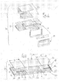
- an oven structure 30 comprises a U-shaped module 32, a L-shaped module 34 and a front frame 36.
- the U-shaped module 32 includes an elongated bottom part 50, which may be formed by means of "soft” or flexible tooling, for instance bending tools and cutting machine, whose cost is lower than the one required for buying "hard” or machine formed tools (moulds, press, etc.).
- the U-shaped module 32 defines three portions of the oven structure, specifically: the exterior bottom wall 51 and the two exterior side walls 52, 53.
- the two exterior side walls 52, 53 originally planar with the exterior bottom wall 51 before bending, can be folded along two transversal lines L1, L2, in order to assume a perpendicular direction referred to the plane of the bottom wall 51, and becoming the two exterior side walls 52,53 of the cavity structure 20.
- the bottom part 50 presents U-shaped edges in order to define front and back rail-shaped profiles 61 and 63 respectively, on the longest sides, said two profiles retaining a slab 100 made of insulating material.
- the front and back rail-shaped profiles 61 and 63 present interruptions K for allowing the bending of the bottom part 50.
- the bottom part 50 presents short sides 64, adapted to secure the L-shaped module 34 to the U-shaped module 32.
- the front and back profiles 61 and 63 are adapted to be fixed to inner walls 58, 59, 60 in order to define a sort of box structure in which the insulating slab 100 is inserted.
- the bottom part 50 also includes coupling slots 54, 55 placed on the front profile 61 by which two hinges receivers 56, 57 ( Fig. 2 ) are secured.
- the two hinge receivers 56, 57 are fixed to the coupling slots 54, 55 by means of screws or rivets, or by any other known fastening technology, including spot welding.
- the two hinge receivers 56, 57 will support the oven door 99 ( Fig. 12 , 13 ), when applied to the oven structure 30.
- the coupling slots 54, 55, and therefore the hinge receivers 56,57 are preferably located on two exterior side wall parts 52, 53, but can be also located in any other zone of the bottom part 50.
- the hinge receivers can be located on a front frame that will be described in the following.
- the oven door can present a single hinge, requiring only one hinge receiver to support it.
- the inner central bottom wall 58, ( Fig.3, 4 , 10 , 11 ) and the two separate inner sides walls 59, 60 are the interior parts of the cavity structure 20 and are fastened to the rail-shaped profiles 61 and 63 of the elongated bottom part 50 in order to keep the insulating slab 100 enclosed.
- the slab 100 is superposed, entirely or partially, to the bottom part 50 insulating the elongated bottom part 50 from the inner walls 58, 59, 60 in the assembled configuration.
- the inner side walls 59, 60 present slots 54A to allow the coupling of the hinges through them.
- the three inner walls 58, 59, 60 are secured to the profiles 61 and 63 of the bottom part 50 by means of screws or rivets, or by any other known technology including spot welding.
- the hinge receivers are directly positioned and secured to the inner sides walls 59, 60.
- the hinges are assembled with the U-shaped module or on the door frame and the hinge receivers are mounted on the oven door.
- the peculiar design of an oven according to the present invention allows to obtain ovens of different overall dimensions and volume by varying the length h ( Fig. 2 ) of the exterior walls 52,53, of the bottom part 50 and, in the same manner, the length h of the related lateral sides walls 59, 61 and of the upper wall part 81 ( Fig. 8 ).
- This parameterization of the length h would not change the cost of the tooling operation for this part, but would provide versatility to the modular oven.
- the low cost of the tooling for this construction can provide a significant competitiveness for the mass production of this oven.
- the U-shaped module 32 has therefore a compact multi-layer structure, that is foldable, on which a first layer is given by the elongated bottom part 50, a second layer being given by the slab 100 of insulating material, and a third layer is defined by the interior bottom and sides walls 58, 59, 60.
- the L-shaped module 34 includes a elongated top part 80, which is created by means of "soft" tools as well, defining two portions of the oven structure, i.e. an exterior upper wall part 81 and an exterior back side wall 82.
- the two portions of the elongated top part 80 originally planar, can be relatively folded along a line L3, so that the exterior upper wall portion 81 assumes a perpendicular position with reference to the exterior back side wall portion 82.
- Two slabs of insulating material 110, 111 are disposed to cover the elongated top part 80, insulating it from the interior panels of the cavity structure 20, namely inner upper wall element 83, and inner back side wall 84, connected and secured to the top part 80.
- the design of the elongated top part 80 also includes rail-shaped profiles 85 ( Fig. 8 ) on the long sides of the elongated top part 80, such profiles being the two lateral closures of the top part 80 and retaining the two slabs of insulation material.
- the rail-shaped profiles 85 present interruptions J for allowing the bending of the top part 80.
- the rail-shaped profiles 85 are adapted to secure the U-shaped module 32 to the L-shaped module 34.
- the interior side 87 of the top part 80 presents snap slots 86 adapted to be fixed to an inner upper wall part 83 and to an inner back side wall 84, in order to define a sort of box structures in which the insulating slabs 110, 111 are enclosed.
- the two inner walls 83, 84 ( figure 8 ) are then secured to snap slots 86 of the top part 80.
- the L-shaped module 34 has a compact multi-layer structure, that is foldable, on which the first layer is the top part 80, a second layer is given by the insulation material slabs 110, 111, and a third layer is defined by the interior upper and back walls 83,84.
- the cavity structure 20 can be obtained by folding the U-shaped module 32 and the L-shaped module 34 according Fig. 10 , and then connecting together the modules U, L on their respective edges 64, 85.
- the cavity structure 20 presents one frontal opening 31 ( Fig.11 and 15 ), through which the food can be inserted.
- the entire cavity structure 20 can be made of plastic material, instead of metal.
- the entire cavity structure 20 can be made of ceramic materials.
- the entire cavity structure 20 can be made of a mixed composition of materials (i.e. having the inner walls made of stainless steel material and the outers walls made of plastic).
- a frontal frame 36 made of metal is the frontal portion of the oven structure 30 that has to be connected to the cavity structure 20.
- the frontal frame 36 may comprise door bumpers, door gasket and/or door switches. It also comprises a control panel support structure 44, to which an user interface panel 45 and the related control box 33 are secured, and all the electrical components, described as follows, required to make the oven work.
- the control panel structure 44 and/or the control box 33 support the oven control elements, like the rotary switch selector 28, the thermostat device 29, the oven timer 27 or the oven control unit, a cooling fan (such component being not shown in the drawings).
- the control box 33 is connected to the backside of the control panel structure 44 to enclose the oven control elements.
- the user interface panel 45 is therefore applied to the front side of the control panel structure 44 presenting a display (not shown), indicators (not shown), thermostat knob 29, a function selector knob 28, a timer knob 27 and the user interface elements needed to the user for setting the oven.
- the front frame 36 To the front frame 36 are also fixed all the electrical elements of the oven, such as temperature sensor (not shown), oven cavity light 49, heating elements 34, 35, door latching system (not shown), oven cavity fan (not shown), oven cooling fan (not shown). These active elements are electrically connected through a harness system (not shown) that is entirely enclosed by front frame 36 and by the control box 33.
- the heating elements 34, 35 are pivotally connected to the front frame 36, in order to allow an independent rotation of about 90° of such heating elements 34, 35 (as indicated by the arrows in Fig. 12 and 13 ). Both the heating elements 34, 35 can assume at least two positions. In the first position the heating elements 34, 35 are substantially planar with the plane of the frame 36.
- the heating elements are substantially perpendicular to the plane of the front frame 36.
- This second position is the working position of the heating elements 34, 35 activated.
- the possibility to rotate the heating elements 34, 35 of the assembled oven improves the clean-ability of the modular oven.
- the rotation of the heating elements 34, 35 also provides a compact structure that facilitates the packaging and the transportation of the frontal frame 36.
- the front frame 36 is aligned, connected and secured to the oven cavity structure 20 generating the oven structure 30. Consequence of the front frame 36 construction is an improved versatility of the oven.
- a glass oven door 99 provided with hinges 42, 43 is connected through the hinge receivers 56, 57 to the oven structure 30, closing the oven cavity frontal opening 31.
- the oven has to be installed into the supporting cabinet or furniture and, the electrical connections need to be completed and the heating elements 34, 35 need to be positioned in their horizontal position.
- the terminals block (not shown) for the power supply connection is located in the area of the control box 33.
- the oven according to the present invention presents a compact structure of its composing modules 32, 34, and of its front frame 36, resulting in a simple and quick assembling operation.
- control panel structure together with the oven control elements and the user interface panel is integrated with the L-shaped module that in this case presents a second folding line.
- control panel structure together with the oven control elements and the user interface panel is integrated with the oven door 99.
- the oven has a modular construction in which only one of the modules (i.e. the frontal frame 36) includes all the active and electric parts, like heating elements, motor wiring etc.; while the other modules are just "passive", in the sense that they do not have electrical components and electrical connections.
- some of the electrical elements required to make the oven work are integrated into the U-shaped 32 and/or the L-shaped 34 modules and/or in the front frame 36, presenting electrical/electronic connection elements (not shown) between said modules 32, 34 and the front frame 36.
- the thermostat 120 is integrated with the L-shaped module 34 and is connected to the thermostat knob 29, which is located on the user interface panel 45, by means of cardanic transmission system 38.
- the oven structure 30 includes a microwave generators, and the U-shaped module and/or the L-shaped module include wave guides.
- the modular oven according to the present invention requires a low investment cost and it is particularly suitable for manufacturing processes presenting low level of automated assembly.
- the modular oven according to the present invention can have the most simple modules (i.e. the ones without electrical components, as the modules U and L- shaped 32 and 34) remotely fabricated and separately shipped to the oven assembling location, improving the competitiveness of the manufacturing process.
- all the electrical elements can be integrated with the front frame 36, resulting in a simplification of the oven construction and of servicing thereof.
- the oven according to the present invention is composed by few, simply constructed modules thermally insulated, easy to be transported due to their compact shape.
- Such modular structure of the oven is simple to assemble, even for common people that, without having specific knowledge, can buy, transport and assemble the oven by themselves.
Landscapes
- Engineering & Computer Science (AREA)
- Chemical & Material Sciences (AREA)
- Combustion & Propulsion (AREA)
- Mechanical Engineering (AREA)
- General Engineering & Computer Science (AREA)
- Electric Ovens (AREA)
- Electric Stoves And Ranges (AREA)
Abstract
Description
- The present invention relates to a compact modular oven having a simple structure. More particularly, it relates to an oven whose structure is simply fabricated by connecting together two structural modules with a front frame, to which all the electrical elements making the oven work are connected.
- Usually, the structure of a domestic oven includes a solid and enameled cavity, which is formed and assembled by means of hard tooling (i.e. moulds, hydraulic presses etc.). A layer of insulation material is superposed to the cavity and an external chassis encloses and sustains all. The single parts of the structure are mainly assembled during the manufacturing process and the transportation of the oven, being not modular, requires a lot of space that is not efficiently used.
- In the patent literature solutions of modular ovens are already disclosed, provided only with simple and basic features.
- From
GB 2084716 - From
EP0254500 it is known a modular cooking apparatus constructed from one or more modules, not having a compact shape. The cooking means is supported on the back plate panel. -
US5160829 discloses an electric heat-convention stove, which is assembled from several discrete parts and in which the top module contains the stove controls and heating means. -
FR2561357 -
US4245615 discloses a modular construction for cooking ranges which involves the design and manufacture of standardized parts or modules that may be used in many different models of ranges. This invention applies to gas and electric ranges. -
US2612590 discloses a sectional, electric kitchen range selectively assembled from a plurality of basic units based on user preference. -
US3428039 shows an oven formed from foldable walls. -
US5548102 teaches about ovens having rotating grill elements to improve cooking performances and clean-ability of the oven itself.
It is not disclosed in the art a modular, thermally insulated oven composed by few and simply constructed modules that are easy to be transported due to a compact shape, and that it is simple to assemble even for common people that, without having specific knowledge, can buy, transport and assemble the oven by themselves. In fact, what is disclosed in the art presents an appreciable complexity for the assembly of the parts, requiring the presence of technical experts.
An object of the present invention is therefore to provide an oven that does not present the drawbacks of the prior art and an assembly method thereof.
This object is reached by an oven whose cavity structure is easily obtainable by the assembly of two modules that have a multi layer compact structure, already including the thermal insulation material. The electrical elements such as, heaters, sensors, controls, user interface, fan with motors, terminal blocks, etc. are all integrated into a third component, the oven front frame. To obtain a compact structure of the front frame during its transportation, the heating elements can be rotated parallel to the frame. A detachable door closes the oven cavity as in traditional ovens.
Other features and advantages of the present invention will become readily apparent to the skilled artisan from the following detailed description when read in light of the accompanying drawings, in which: -
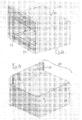
Figure 1 is an exploded view of the oven structure according to the present invention; -
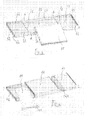
Figures 2 to 5 show the assembly sequence of the U-shaped module according to the present invention; -
Figures 6 to 9 show the assembly sequence of the L-shaped module according to the present invention; -
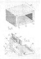
Figures 10 and11 show the assembly of the oven cavity structure according to the present invention; -
Figures 12 and13 show the front frame configuration according to the present invention, showing the positioning of the heating elements and the way to assemble the oven door; -
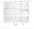
Figures 14 to 16 show the assembly of the oven structure according to the present invention; -
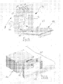
Fig. 17 shows a detail of an alternative thermostat connection to the oven according to the present invention. - With reference to
Fig. 1 to 5 anoven structure 30 comprises aU-shaped module 32, a L-shaped module 34 and afront frame 36. The U-shapedmodule 32 includes an elongated bottom part 50, which may be formed by means of "soft" or flexible tooling, for instance bending tools and cutting machine, whose cost is lower than the one required for buying "hard" or machine formed tools (moulds, press, etc.). The U-shapedmodule 32 defines three portions of the oven structure, specifically: the exterior bottom wall 51 and the twoexterior side walls exterior side walls exterior side walls cavity structure 20. - With reference to
Fig.2 the bottom part 50 presents U-shaped edges in order to define front and back rail-shaped profiles slab 100 made of insulating material. - The front and back rail-
shaped profiles
The bottom part 50 presentsshort sides 64, adapted to secure the L-shaped module 34 to the U-shapedmodule 32. As shown inFig. 3 and 4 the front andback profiles inner walls insulating slab 100 is inserted.
The bottom part 50 also includescoupling slots front profile 61 by which two hinges receivers 56, 57 (Fig. 2 ) are secured. The twohinge receivers 56, 57 are fixed to thecoupling slots hinge receivers 56, 57 will support the oven door 99 (Fig. 12 ,13 ), when applied to theoven structure 30.
Thecoupling slots hinge receivers 56,57 are preferably located on two exteriorside wall parts - The inner
central bottom wall 58, (Fig.3, 4 ,10 ,11 ) and the two separateinner sides walls 59, 60 are the interior parts of thecavity structure 20 and are fastened to the rail-shaped profiles insulating slab 100 enclosed. According to this feature, theslab 100 is superposed, entirely or partially, to the bottom part 50 insulating the elongated bottom part 50 from theinner walls inner side walls 59, 60 present slots 54A to allow the coupling of the hinges through them. - The three
inner walls profiles - In an alternative embodiment (not shown) the hinge receivers are directly positioned and secured to the
inner sides walls 59, 60. - In a further possible embodiment (not shown) the hinges are assembled with the U-shaped module or on the door frame and the hinge receivers are mounted on the oven door.
- The peculiar design of an oven according to the present invention allows to obtain ovens of different overall dimensions and volume by varying the length h (
Fig. 2 ) of theexterior walls lateral sides walls 59, 61 and of the upper wall part 81 (Fig. 8 ).
This parameterization of the length h would not change the cost of the tooling operation for this part, but would provide versatility to the modular oven. Moreover, the low cost of the tooling for this construction can provide a significant competitiveness for the mass production of this oven.
By assembling all the previously described parts, and then folding thesides walls U-shaped module 32 is obtained. The U-shapedmodule 32 has therefore a compact multi-layer structure, that is foldable, on which a first layer is given by the elongated bottom part 50, a second layer being given by theslab 100 of insulating material, and a third layer is defined by the interior bottom andsides walls - With reference to
Fig.6 to 10 , in a similar way the L-shaped module 34 includes a elongatedtop part 80, which is created by means of "soft" tools as well, defining two portions of the oven structure, i.e. an exteriorupper wall part 81 and an exteriorback side wall 82. The two portions of the elongatedtop part 80, originally planar, can be relatively folded along a line L3, so that the exteriorupper wall portion 81 assumes a perpendicular position with reference to the exterior backside wall portion 82. - Two slabs of insulating material 110, 111 (
Fig.8 ), for instance mats of glass wool or the like, are disposed to cover the elongatedtop part 80, insulating it from the interior panels of thecavity structure 20, namely innerupper wall element 83, and innerback side wall 84, connected and secured to thetop part 80. - The design of the elongated
top part 80 also includes rail-shaped profiles 85 (Fig. 8 ) on the long sides of the elongatedtop part 80, such profiles being the two lateral closures of thetop part 80 and retaining the two slabs of insulation material. The rail-shaped profiles 85 present interruptions J for allowing the bending of thetop part 80. The rail-shaped profiles 85 are adapted to secure theU-shaped module 32 to the L-shaped module 34.
The interior side 87 of thetop part 80 presentssnap slots 86 adapted to be fixed to an innerupper wall part 83 and to an innerback side wall 84, in order to define a sort of box structures in which the insulating slabs 110, 111 are enclosed. The twoinner walls 83, 84 (figure 8 ) are then secured tosnap slots 86 of thetop part 80. Assembling together the elongatedtop part 80 with the insulating slabs 110, 111 and theinner walls Fig. 11 ), and by folding the two walls of the module along the line L3, a L-shaped module 34 is obtained. The L-shapedmodule 34 has a compact multi-layer structure, that is foldable, on which the first layer is thetop part 80, a second layer is given by the insulation material slabs 110, 111, and a third layer is defined by the interior upper andback walls - With reference to
Fig. 10 and11 thecavity structure 20 can be obtained by folding theU-shaped module 32 and the L-shapedmodule 34 accordingFig. 10 , and then connecting together the modules U, L on theirrespective edges - The
cavity structure 20 presents one frontal opening 31 (Fig.11 and15 ), through which the food can be inserted. - In a different (not shown) embodiment, the
entire cavity structure 20 can be made of plastic material, instead of metal. In a second different embodiment, theentire cavity structure 20 can be made of ceramic materials. - In another embodiment the
entire cavity structure 20 can be made of a mixed composition of materials (i.e. having the inner walls made of stainless steel material and the outers walls made of plastic). - With reference to
Fig. 12 to 16 afrontal frame 36 made of metal is the frontal portion of theoven structure 30 that has to be connected to thecavity structure 20. Thefrontal frame 36 may comprise door bumpers, door gasket and/or door switches. It also comprises a controlpanel support structure 44, to which anuser interface panel 45 and therelated control box 33 are secured, and all the electrical components, described as follows, required to make the oven work. - The
control panel structure 44 and/or thecontrol box 33 support the oven control elements, like therotary switch selector 28, thethermostat device 29, theoven timer 27 or the oven control unit, a cooling fan (such component being not shown in the drawings). Thecontrol box 33 is connected to the backside of thecontrol panel structure 44 to enclose the oven control elements. Theuser interface panel 45 is therefore applied to the front side of thecontrol panel structure 44 presenting a display (not shown), indicators (not shown),thermostat knob 29, afunction selector knob 28, atimer knob 27 and the user interface elements needed to the user for setting the oven.
To thefront frame 36 are also fixed all the electrical elements of the oven, such as temperature sensor (not shown), oven cavity light 49,heating elements front frame 36 and by thecontrol box 33.
Theheating elements front frame 36, in order to allow an independent rotation of about 90° ofsuch heating elements 34, 35 (as indicated by the arrows inFig. 12 and13 ). Both theheating elements heating elements frame 36. In the second position, the heating elements are substantially perpendicular to the plane of thefront frame 36. This second position is the working position of theheating elements heating elements heating elements frontal frame 36.
According toFig. 14 to 16 , thefront frame 36 is aligned, connected and secured to theoven cavity structure 20 generating theoven structure 30.
Consequence of thefront frame 36 construction is an improved versatility of the oven. In fact, it is possible to obtain a family of ovens, each of them having different features, just simply changing the electrical elements configuring thefront frame 36; from a manufacturing standpoint this means having a different version of the modular oven, for each differentfront frame 36 and for each of the needed configuration, improving the standardization of the manufacturing assembly process.
Finally, aglass oven door 99, provided withhinges 42, 43 is connected through thehinge receivers 56, 57 to theoven structure 30, closing the oven cavityfrontal opening 31.
In order to properly operate, the oven has to be installed into the supporting cabinet or furniture and, the electrical connections need to be completed and theheating elements control box 33. The oven according to the present invention presents a compact structure of its composingmodules front frame 36, resulting in a simple and quick assembling operation. - In a first alternative (not shown) embodiment, the control panel structure together with the oven control elements and the user interface panel is integrated with the L-shaped module that in this case presents a second folding line.
In a second alternative embodiment (not shown), the control panel structure together with the oven control elements and the user interface panel is integrated with theoven door 99. - According to the previously described embodiments, the oven has a modular construction in which only one of the modules (i.e. the frontal frame 36) includes all the active and electric parts, like heating elements, motor wiring etc.; while the other modules are just "passive", in the sense that they do not have electrical components and electrical connections.
- In a third alternative embodiment (not shown), some of the electrical elements required to make the oven work are integrated into the U-shaped 32 and/or the L-shaped 34 modules and/or in the
front frame 36, presenting electrical/electronic connection elements (not shown) between saidmodules front frame 36. - In a different embodiment, described in
Fig 17 , thethermostat 120 is integrated with the L-shapedmodule 34 and is connected to thethermostat knob 29, which is located on theuser interface panel 45, by means ofcardanic transmission system 38. - In a last (not shown) alternative embodiment, the
oven structure 30 includes a microwave generators, and the U-shaped module and/or the L-shaped module include wave guides.
The modular oven according to the present invention requires a low investment cost and it is particularly suitable for manufacturing processes presenting low level of automated assembly. Moreover, the modular oven according to the present invention can have the most simple modules (i.e. the ones without electrical components, as the modules U and L- shaped 32 and 34) remotely fabricated and separately shipped to the oven assembling location, improving the competitiveness of the manufacturing process. In the modular oven all the electrical elements can be integrated with thefront frame 36, resulting in a simplification of the oven construction and of servicing thereof.
The oven according to the present invention is composed by few, simply constructed modules thermally insulated, easy to be transported due to their compact shape. Such modular structure of the oven is simple to assemble, even for common people that, without having specific knowledge, can buy, transport and assemble the oven by themselves.
Claims (12)
- An oven, comprising: a U-shaped module (32) having a multi-layer structure (50, 100, 58, 59, 60), a L-shaped module (34) having a multi-layer structure (80, 83, 84) wherein the U-shaped module (32) and the L-shaped module (34) are joinable together to form an oven cavity (20), and a front frame (36) connected with the oven cavity (20) including at least one electrical element (34, 35, 49).
- An oven as in claim 1 characterized in that the front frame (36) includes oven control elements (27, 28, 29).
- An oven as in claim 1 including a door (99) for closing the oven cavity (20) characterized in that either the U-shaped module (32) or the front frame (36) or the door (99) include at least one door hinge (42, 43, 56, 57) supporting element.
- An oven as in claim 1 characterized in that the U-shaped module (32) comprises:- a planar element (50) defining the exterior bottom wall (51) and the two exterior sides walls (52, 53) of the oven structure,- an enclosed layer (100) of insulation material,- at least one inner cavity oven wall element defining the inner bottom wall (58) and two inner sides walls (59, 60) of the oven structure;and in that the L-shaped module (34) comprises:- a planar element (80) defining the exterior upper wall (81) and the exterior back side wall (82) of the oven cavity (20),- an enclosed layer of insulation material (110, 111), and- at least one inner cavity oven wall element defining the inner upper wall (83) and the inner back side wall (84) of the oven cavity (20).
- An oven as in claim 1, characterized in that the U-shaped module (32) and the L-shaped module (34) are foldable.
- An oven as in claim 1 characterized in that at least the construction of one of the modules, either the U-shaped module (32) or the L-shaped module (34), includes one planar element (50, 80) presenting a rail-shaped profile (85, 61, 63) cooperating with at least one separate panel (58, 59, 60, 83, 84) connected thereto.
- An oven as in claim 1 or 2, characterized in that the front frame (36) is provided with foldable heating element (34, 35).
- An oven as in claim 1, characterized in that the front frame (36) is provided with a component selected in the group consisting of:- oven cavity light,- oven cavity fan,- oven cooling fan,- heating element,- microwave generator or a combination thereof.
- An oven as in claim 1, characterized in that the L-shaped element (34) or the U-shaped element (32) or both said elements are provided with wave-guides and with wave openings located in the inner cavity oven wall sides (58, 59, 60, 83, 84).
- A method to assemble the oven as in claim 1, the assembly steps comprising:- assembling the L-shaped module (34);- assembling the U-shaped module (32);- connecting the L-shaped module (34) with the U-shaped (32) module forming the oven cavity(20);- connecting the front frame (36) with the oven cavity (20) forming the oven structure(30);- assembling the oven door (99); and- assembling oven door (99) to the oven structure (30).
- A method for assembling the oven as in claim 10, the assembling steps of the L-shaped module (34) comprising:- attaching insulation (110, 111);- connecting at least an inner wall (83, 84); and- folding into L shape.
- A method for assembling the oven as in claim 10, the assembling steps of the U-shaped (32) module comprising:- attaching insulation (100);- connecting at least an inner wall (58, 59, 60); and- folding into U shape.
Priority Applications (2)
| Application Number | Priority Date | Filing Date | Title |
|---|---|---|---|
| ES07105495.1T ES2537565T3 (en) | 2007-04-02 | 2007-04-02 | Compact modular oven |
| EP20070105495 EP1978310B1 (en) | 2007-04-02 | 2007-04-02 | Modular oven structure |
Applications Claiming Priority (1)
| Application Number | Priority Date | Filing Date | Title |
|---|---|---|---|
| EP20070105495 EP1978310B1 (en) | 2007-04-02 | 2007-04-02 | Modular oven structure |
Publications (2)
| Publication Number | Publication Date |
|---|---|
| EP1978310A1 true EP1978310A1 (en) | 2008-10-08 |
| EP1978310B1 EP1978310B1 (en) | 2015-04-29 |
Family
ID=38577557
Family Applications (1)
| Application Number | Title | Priority Date | Filing Date |
|---|---|---|---|
| EP20070105495 Not-in-force EP1978310B1 (en) | 2007-04-02 | 2007-04-02 | Modular oven structure |
Country Status (2)
| Country | Link |
|---|---|
| EP (1) | EP1978310B1 (en) |
| ES (1) | ES2537565T3 (en) |
Cited By (6)
| Publication number | Priority date | Publication date | Assignee | Title |
|---|---|---|---|---|
| DE102011107847A1 (en) * | 2011-07-01 | 2013-01-03 | Forschungszentrum Jülich GmbH | Modular furnace system |
| CN104067057A (en) * | 2012-01-13 | 2014-09-24 | 伊莱克斯家用产品股份有限公司 | Oven cavity and oven |
| CN104367203A (en) * | 2014-11-20 | 2015-02-25 | 广东美的厨房电器制造有限公司 | Inner container used for electric oven and electric oven provided with same |
| US10850996B2 (en) | 2015-01-29 | 2020-12-01 | Omya International Ag | Process for manufacturing a solution of an earth alkali hydrogen carbonate |
| CN112914348A (en) * | 2021-03-01 | 2021-06-08 | 广东美的厨房电器制造有限公司 | Cooking device |
| CN112954840A (en) * | 2021-03-01 | 2021-06-11 | 广东美的厨房电器制造有限公司 | Cooking device |
Families Citing this family (2)
| Publication number | Priority date | Publication date | Assignee | Title |
|---|---|---|---|---|
| CN216147866U (en) * | 2020-11-06 | 2022-04-01 | 广东格兰仕集团有限公司 | Cavity structure for containing cooking food materials and cooking equipment |
| WO2025175195A1 (en) * | 2024-02-14 | 2025-08-21 | Traina Peter Nicholas | Portable interlocking modular oven |
Citations (2)
| Publication number | Priority date | Publication date | Assignee | Title |
|---|---|---|---|---|
| US3534724A (en) * | 1963-05-24 | 1970-10-20 | Gunter Petz | Housing for a forced draught space heater |
| EP0394978A2 (en) * | 1989-04-25 | 1990-10-31 | Sharp Kabushiki Kaisha | Frame construction for microwave oven and the like |
-
2007
- 2007-04-02 ES ES07105495.1T patent/ES2537565T3/en active Active
- 2007-04-02 EP EP20070105495 patent/EP1978310B1/en not_active Not-in-force
Patent Citations (2)
| Publication number | Priority date | Publication date | Assignee | Title |
|---|---|---|---|---|
| US3534724A (en) * | 1963-05-24 | 1970-10-20 | Gunter Petz | Housing for a forced draught space heater |
| EP0394978A2 (en) * | 1989-04-25 | 1990-10-31 | Sharp Kabushiki Kaisha | Frame construction for microwave oven and the like |
Cited By (7)
| Publication number | Priority date | Publication date | Assignee | Title |
|---|---|---|---|---|
| DE102011107847A1 (en) * | 2011-07-01 | 2013-01-03 | Forschungszentrum Jülich GmbH | Modular furnace system |
| CN104067057A (en) * | 2012-01-13 | 2014-09-24 | 伊莱克斯家用产品股份有限公司 | Oven cavity and oven |
| CN104367203A (en) * | 2014-11-20 | 2015-02-25 | 广东美的厨房电器制造有限公司 | Inner container used for electric oven and electric oven provided with same |
| US10850996B2 (en) | 2015-01-29 | 2020-12-01 | Omya International Ag | Process for manufacturing a solution of an earth alkali hydrogen carbonate |
| CN112914348A (en) * | 2021-03-01 | 2021-06-08 | 广东美的厨房电器制造有限公司 | Cooking device |
| CN112954840A (en) * | 2021-03-01 | 2021-06-11 | 广东美的厨房电器制造有限公司 | Cooking device |
| CN112954840B (en) * | 2021-03-01 | 2023-11-03 | 广东美的厨房电器制造有限公司 | cooking device |
Also Published As
| Publication number | Publication date |
|---|---|
| EP1978310B1 (en) | 2015-04-29 |
| ES2537565T3 (en) | 2015-06-09 |
Similar Documents
| Publication | Publication Date | Title |
|---|---|---|
| EP1978310B1 (en) | Modular oven structure | |
| US5190026A (en) | Modular countertop cooking system | |
| KR19980018249A (en) | System consisting of kitchen unit housing unit and / or kitchen unit | |
| EP1738120A2 (en) | Modular refrigeration and/or freezer appliance | |
| EP3404332B1 (en) | Cooking appliance | |
| JPH0257831A (en) | Housing for multipurpose facility | |
| KR102559759B1 (en) | Control Panel and Household Appliance Having the same | |
| US12429229B2 (en) | Locating features for a front panel of a domestic appliance door | |
| EP0254500A1 (en) | Improvements relating to cooking apparatus | |
| KR100735185B1 (en) | Mounting structure of printed circuit board of electric oven | |
| EP1817530A1 (en) | Cabinet with an internal framework for air conditioner installation | |
| JPH1114068A (en) | External panel assembly equipment for microwave oven | |
| KR20100064643A (en) | A aooker | |
| EP1891377B1 (en) | A cooking device with terminal box | |
| JP6793591B2 (en) | Cooker | |
| CN223569200U (en) | A modular oven | |
| KR200386575Y1 (en) | A control panel of electric-oven | |
| JP7699568B2 (en) | heating cooker | |
| EP2202345B1 (en) | Manufacturing process of an appliance cabinet and cabinet so manufactured | |
| CN116327006B (en) | Cooking equipment | |
| EP1764560A1 (en) | Domestic oven | |
| US20080308544A1 (en) | Multifunctional Roasting Oven | |
| EP2930435B1 (en) | Household cooking appliance | |
| JP2574954Y2 (en) | Cooking device | |
| KR100672598B1 (en) | Support structure of the oven cavity |
Legal Events
| Date | Code | Title | Description |
|---|---|---|---|
| PUAI | Public reference made under article 153(3) epc to a published international application that has entered the european phase |
Free format text: ORIGINAL CODE: 0009012 |
|
| AK | Designated contracting states |
Kind code of ref document: A1 Designated state(s): AT BE BG CH CY CZ DE DK EE ES FI FR GB GR HU IE IS IT LI LT LU LV MC MT NL PL PT RO SE SI SK TR |
|
| AX | Request for extension of the european patent |
Extension state: AL BA HR MK RS |
|
| 17P | Request for examination filed |
Effective date: 20090402 |
|
| AKX | Designation fees paid |
Designated state(s): DE ES FR GB IT |
|
| GRAP | Despatch of communication of intention to grant a patent |
Free format text: ORIGINAL CODE: EPIDOSNIGR1 |
|
| INTG | Intention to grant announced |
Effective date: 20150210 |
|
| GRAS | Grant fee paid |
Free format text: ORIGINAL CODE: EPIDOSNIGR3 |
|
| GRAA | (expected) grant |
Free format text: ORIGINAL CODE: 0009210 |
|
| AK | Designated contracting states |
Kind code of ref document: B1 Designated state(s): DE ES FR GB IT |
|
| REG | Reference to a national code |
Ref country code: GB Ref legal event code: FG4D |
|
| REG | Reference to a national code |
Ref country code: ES Ref legal event code: FG2A Ref document number: 2537565 Country of ref document: ES Kind code of ref document: T3 Effective date: 20150609 |
|
| REG | Reference to a national code |
Ref country code: DE Ref legal event code: R096 Ref document number: 602007041224 Country of ref document: DE Effective date: 20150611 |
|
| REG | Reference to a national code |
Ref country code: DE Ref legal event code: R097 Ref document number: 602007041224 Country of ref document: DE |
|
| PLBE | No opposition filed within time limit |
Free format text: ORIGINAL CODE: 0009261 |
|
| STAA | Information on the status of an ep patent application or granted ep patent |
Free format text: STATUS: NO OPPOSITION FILED WITHIN TIME LIMIT |
|
| REG | Reference to a national code |
Ref country code: FR Ref legal event code: PLFP Year of fee payment: 10 |
|
| 26N | No opposition filed |
Effective date: 20160201 |
|
| PGFP | Annual fee paid to national office [announced via postgrant information from national office to epo] |
Ref country code: ES Payment date: 20160311 Year of fee payment: 10 |
|
| REG | Reference to a national code |
Ref country code: FR Ref legal event code: PLFP Year of fee payment: 11 |
|
| REG | Reference to a national code |
Ref country code: FR Ref legal event code: PLFP Year of fee payment: 12 |
|
| REG | Reference to a national code |
Ref country code: ES Ref legal event code: FD2A Effective date: 20180704 |
|
| PG25 | Lapsed in a contracting state [announced via postgrant information from national office to epo] |
Ref country code: ES Free format text: LAPSE BECAUSE OF NON-PAYMENT OF DUE FEES Effective date: 20170403 |
|
| PGFP | Annual fee paid to national office [announced via postgrant information from national office to epo] |
Ref country code: GB Payment date: 20200325 Year of fee payment: 14 |
|
| PGFP | Annual fee paid to national office [announced via postgrant information from national office to epo] |
Ref country code: FR Payment date: 20200312 Year of fee payment: 14 |
|
| PGFP | Annual fee paid to national office [announced via postgrant information from national office to epo] |
Ref country code: DE Payment date: 20200317 Year of fee payment: 14 |
|
| PGFP | Annual fee paid to national office [announced via postgrant information from national office to epo] |
Ref country code: IT Payment date: 20200312 Year of fee payment: 14 |
|
| REG | Reference to a national code |
Ref country code: DE Ref legal event code: R119 Ref document number: 602007041224 Country of ref document: DE |
|
| GBPC | Gb: european patent ceased through non-payment of renewal fee |
Effective date: 20210402 |
|
| PG25 | Lapsed in a contracting state [announced via postgrant information from national office to epo] |
Ref country code: FR Free format text: LAPSE BECAUSE OF NON-PAYMENT OF DUE FEES Effective date: 20210430 Ref country code: GB Free format text: LAPSE BECAUSE OF NON-PAYMENT OF DUE FEES Effective date: 20210402 Ref country code: DE Free format text: LAPSE BECAUSE OF NON-PAYMENT OF DUE FEES Effective date: 20211103 |
|
| PG25 | Lapsed in a contracting state [announced via postgrant information from national office to epo] |
Ref country code: IT Free format text: LAPSE BECAUSE OF NON-PAYMENT OF DUE FEES Effective date: 20200402 |
|
| PG25 | Lapsed in a contracting state [announced via postgrant information from national office to epo] |
Ref country code: IT Free format text: LAPSE BECAUSE OF NON-PAYMENT OF DUE FEES Effective date: 20210402 |